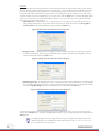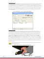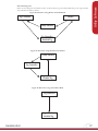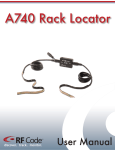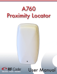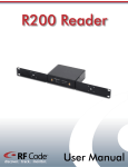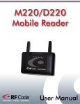
1
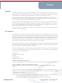
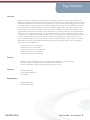
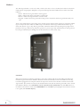
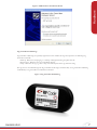
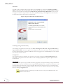
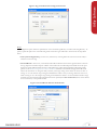
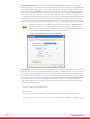
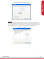
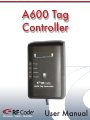
A600 Tag
Controller
discover. track. monitor.
User Manual
Contents
Preface
3
3
3
4
4
Tag Controller
5
5
5
5
5
6
6
7
8
8
8
8
8
9
11
12
13
13
14
14
14
16
16
17
18
18
Warranty & Service
19
19
19
19
19
Trademarks
FCC Compliance
CE Compliance
Copyright Statement
Overview Features
Contents
Requirements
Hardware
Installation
Tag Controller-Enabled Tags
Utility Software
Installation
Launching the Tag Controller Utility
Configuration
Tag Controller
Reader
Group Codes
Passcodes
Log Files
Passcode File Import
View Log File
Using Tag Controller to Alter Tag Status
Reader Assisted Method
Manual Entry Method
Stand-Alone Operation
Data Flow Diagrams
Upgrading Environmental Limits
Limited Standard Warranty Terms
Standard Warranty Limitations Obtaining Service & Support
RF Code Customer Support
PN00902 REV01
Tag Controller User Manual 2
Preface
Trademarks
RF CodeTM and the RF Code logo are trademarks of RF Code, Inc. The Bluetooth® word mark and logos are registered trademarks owned by Bluetooth SIG, Inc. and any use of such marks by RF Code is under license. All other
product names are copyright and registered trademarks or trade names of their respective owners.
Information in this document is provided solely to enable system and software implementors to use RF Code
products. There are no express or implied copyright licenses granted hereunder to design or fabricate any integrated
circuits or integrated circuits based on the information in this document.
RF Code reserves the right to make changes without further notice to any products herein. RF Code makes no warranty, representation or guarantee regarding the suitability of its products for any particular purpose, nor does RF
Code assume any liability arising out of the application or use of any product, and specifically disclaims any and all
liability, including without limitation consequential or incidental damages.
The user of this system is cautioned that any changes or modifications to this system, not expressly approved by RF
Code, Inc., could void the warranty.
FCC Compliance
This equipment has been tested and found to comply with the limits for a Class A digital device, pursuant to Part 15
of the FCC Rules. These limits are designed to provide reasonable protection against harmful interference when the
equipment is operated in a commercial environment. This equipment generates, uses, and can radiate radio frequency
energy and, if not installed and used in accordance with the instruction manual, may cause harmful interference to
radio communications. Operation of this equipment in a residential area is likely to cause harmful interference, in
which case the user will be required to correct the interference at his own expense.
RF Code is not responsible for any radio or television interference caused by using other than recommended cables
and connectors or by unauthorized changes or modifications to this equipment. Unauthorized changes or modifications could void the user’s authority to operate the equipment.
This device complies with Part 15 of the FCC rules. Operation is subject to the following two conditions: (1) this device may not cause harmful interference, and (2) this device must accept any interference received, including interference that may cause undesired operation.
RF Code, Inc.
9229 Waterford Center Blvd.
Suite 500
Austin, TX 78758
Telephone: 1-512-439-2200
Industry Canada Compliance Statement
This Class A digital apparatus meets the requirements of the Canadian Interference-Causing Equipment Regulations.
Avis de conformité à la réglementation d’Industrie Canada
Cet appareil numérique de la classe A respecte toutes les exigences du Règlement sur le matériel brouilleur du
Canada.
The system is design to operate with RF Code tags – Whose operating frequency is 433.92 MHz which have been
certified or are in the certification process. These devices comply with part 15 of the FCC rules. Operation is subject
to the following two conditions:
(1) these devices may not cause harmful interference, and
(2) these devices must accept any interference received, including interference that may cause undesired operation.
a. FCC ID: P6F2005433 for beacon intervals greater than, or equal to 10 seconds.
b. FCC ID: P6F433MHZ for the security tag with beacon intervals less than 10 seconds.
PN00902 REV01
Tag Controller User Manual 3
CE Compliance
This is a Class A product. In a domestic environment, this product may cause radio interference, in which case the
user may be required to take adequate measures. This equipment complies with the requirements relating to electromagnetic compatibility, EN 55022 class A, the essential protection requirement of Council Directive 89/336/EEC
on the approximation of the laws of the Member States relating to electromagnetic compatibility.
Copyright Statement
Copyright © 2009 RF Code, Inc. All Rights Reserved.
This document, as well as the hardware and firmware described therein, are furnished under license and may only be
used or copied in accordance with the terms of such license. The information in these pages are furnished for informational use only, are subject to change without notice, and should not be construed as a commitment by RF Code,
Inc. RF Code assumes no responsibility or liability for any errors or inaccuracies that may appear in these pages.
Every effort has been made to supply complete and accurate information. However, RF Code assumes no responsibility for its use, or for any infringements of patents or other rights of third parties, which would result.
RF Code, Inc.
9229 Waterford Centre Blvd.
Suite 500
Austin, TX 78758
www.rfcode.com
4
PN00902 REV01
Tag Controller
Overview
RF Code introduces the A600 Tag Controller, Tag Controller Utility software and Tag Controller-enabled Active
RFID Tags with special features that allow tags to beacon on-command or be put to sleep temporarily (to meet radio
transmission interference requirements in certain environments, or to conserve battery life during periods of non-use
or extended storage). A wake-up feature is consequently available to bring the tags out of sleep mode. This new tag
technology provides increased capabilities for inventory and security purposes. The A600 Tag Controller can be
used to control any of the RF Code M-Series or R-Series tags that are labeled as Tag Controller-enabled tags. The
Tag Controller can be used in “Stand-alone” mode, which allows it to perform the beacon now and wake functions
without the use of any application software. The Tag Controller can also be used in “Application” mode in either a
“manual entry” or “reader assisted” fashion. In “manual entry” mode, the utility has no communication with a fixed
or mobile reader and all input data must be entered manually into the application. In “reader assisted” mode the
utility communicates with a fixed or mobile reader to reduce user input and make the “flow” much more automatic.
When reader-assisted, the Tag Controller Utility will communicate to an RF Code reader in one of the following
ways to provide a full feedback loop.
• Network connection to a fixed reader
• Serial connection to a fixed reader
• USB (serial) connection to a mobile reader
• Bluetooth connection to a mobile reader
• Network connection to Zone Manager
Features
• Make tags beacon immediately for asset arrival and removal notification, or for asset locating
• Put tags to sleep to comply with policies that prohibit radio transmission
• Conserve battery life of tags for extended periods of storage or non-use
Contents
• A600 Tag Controller
• Tag Controller Utility CD
• User Manual
Requirements
• Windows XP or Vista
• Tag Controller Utility
PN00902 REV01
Tag Controller User Manual 5
Hardware
The A600 Tag Controller is a 4.37 in (111 mm) x 0.99 in (25.1 mm) x 3.01 in (76.5 mm) device that has an injectionmolded chassis of high-impact ABS plastic. It is powered through the built-in USB connector and has four LED
indicators:
• Power - indicates the Tag Controller is receiving power
• Wake - indicates that the Tag Controller is in wake mode
• Beacon - indicates the Tag Controller is in beacon mode
• Program - indicates that the Tag Controller is being used in conjunction with the Tag Controller Utility software
There is also a Mode button on the surface of the unit that must be depressed when putting Tag Controller-enabled
tags into sleep mode. There will be an audible “beep” that indicates that the Tag Controller has caused the tag to
either wake, beacon or go to sleep. The Tag Controller is directional and functions by placing the top edge in close
proximity to the tag to wake the tag, make the tag beacon or put the tag to sleep. The placement of the Tag Controller and tag are indicated by the labeling with two directional arrows and the word, “Tag”.
Figure 1: A600 Tag Controller
Installation
hen first connecting the A600 Tag Controller to a PC, driver software will need to be installed. This will be perW
formed through the Found New Hardware Wizard that should automatically load when the USB cord of the Tag
Controller is plugged into the computer. Follow the steps in the wizard to locate the driver software for the A600
Tag Controller. This software is located on the Installer CD that came with the A600 Tag Controller. In the “Found
New Hardware Wizard”, select Install from a list of a specific location (Advanced), then click Next. Browse to
the folder on the CD that contains the file RFCUSB.inf, then click OK. If a prompt appears that the driver software
is not signed, click Continue Anyway.
6
PN00902 REV01
Hardware
Figure 2: A600 Hardware Installation Wizard
Tag Controller-Enabled Tags
Tag Controller-enabled tags are specially engineered versions of RF Code tags that respond to the following Tag
Controller commands:
• Wakeup - Will cause a sleeping tag to “wakeup” and begin beaconing at regular intervals.
• Beacon Now - Will cause the tag to immediately beacon.
• Sleep - Will cause the tag to go into a sleep state and will prevent the tag from beaconing.
The tag status is controlled through the Tag Controller and the Tag Controller Utility. A Tag Controller-enabled tag
is identified by a Tag Controller icon indicated on the label.
Figure 3: Tag Controller-Enabled Tag
PN00902 REV01
7
Utility Software
Installation
To install the Tag Controller Utility insert the CD into the CD-ROM drive and click on Install Tag Controller
Utility to begin. If the CD autorun program does not launch the CD main menu, use a Windows Explorer window
to browse to the CD drive and double-click the RF Code Tag Controller Utility CD Menu file to start the autorun program or install the Tag Controller Utility directly by double clicking on the setup.exe file. This will launch
the install wizard. Follow the prompts to install the utility.
Figure 4: Tag Controller Utility Installation Wizard
Launching the Tag Controller Utility
After installing the application from the CD, select Start > All Programs > RF Code > Tag Controller Utility >
Tag Controller Utility to launch the application and display the main screen. The utility is used in conjunction with
the Tag Controller. The Tag Controller’s USB cable needs to be plugged into an available USB port on the computer
that is running the utility software.
Configuration
The configuration features available in this utility can be accessed by navigating to Action>Configuration. This
will produce a Configuration menu. There will be several tabs displaying different configuration options wich are
described below:
Tag Controller
In this configuration option, a Tag Controller unit that is plugged into the computer running the Tag Controller Utility can be discovered. This can be performed through clicking the Discover button. A Tag Controller will need to be
chosen from the drop-down menu. Assign a Controller ID to the device and choose to have the controller “beep”
upon tag confirmation or not by selecting the checkbox. The user can also update the firmware for the tag controller
device by clicking the Upgrade button.
For proper operation, all A600 Tag Controllers must have unique Controller ID numbers. The
default Controller ID is 0.
8
PN00902 REV01
Utility Software
Figure 5: Tag Controller Tab for Configuration Feature
Reader
This configuration option allows for specification of use of manual tag ID entry or reader-assisted tag ID entry. To
specify a particular option one of the following reader connection types will need to chosen from the drop-down
menu:
• None (manual Tag ID entry) - In this case, manual entry of the tag ID in the main screen of the utility is
needed to control the tags.
• Network Reader - In this case, a networked reader will be utilized to discover the tag ID to allow control of
the tag. Input the hostname and port number of the reader. The user ID and password will need to be specified for the reader ONLY IF this has been configured for the reader with the Reader Configuration Utility
(please see the Reader Configuration Utility User Manual available on the Downloads page of the RF Code
website for instructions on using this utility software). The range setting on the reader can also be set here. A
setting of “1” is the shortest range setting and will allow the reader to only see the tags which are closest to it,
while a setting of “8” is the longest range setting and will allow the reader to see the maximum number of tags
possible. Once the network reader information has been specified, the Test Connection button can be clicked
to test connectivity to the specified reader.
Figure 6: Network Reader Selection in Reader Tab
PN00902 REV01
9
• Serial/Bluetooth Reader - In this case, the M220 Mobile Reader will be connected to the PC through a
Bluetooth connection or a fixed reader will be connected through a serial port. A properly configured M220 Bluetooth-enabled Mobile Reader will show up as a COM port in the Windows Device Manager. A reader should
be chosen by clicking the Scan Ports button. This will scan the users computer to find COM ports that have
RF Code readers attached. Select the COM port from the drop down menu and click the Test Connection
button. This will test the connection to the reader and will display the reader identification information. If a
user ID and password have been previously set for the reader using the RF Code Reader Configuration Utility,
these must be entered to interact with the reader. Select a range setting from the drop-down list. A setting of
“1” is the shortest range setting and will allow the reader to only see the tags which are closest to it, while a setting of “8” is the longest range setting and will allow the reader to see the maximum number of tags possible.
If the reader is connected to a PC and is not showing up when you click the Scan Ports button,
make sure that there are not any other programs open that are accessing the COM port that the
reader is using (e.g. RF Code Reader Configuration Utility). This competing application will need
to be exited and the Test Connection button should be clicked again.
Figure 7: Serial/Bluetooth Selection in Reader Tab
• Zone Manager - In this case, all readers being managed by a Zone Manager will be utilized to discover the tag
IDs to allow control of the tags. Input the hostname, port number, user ID and password to connect with the
Zone Manager. The default user ID and password for Zone Manager are blank. Check with the administrator
who configured the Zone Manager to see if security has been enabled for the reader and a custom user id and
password have been set. Once the Zone Manager information has been entered, the Test Connection button
can be clicked to test connectivity to the specified Zone Manager. In order for the Tag Controller Utility to
work with Zone Manager, the report triggers parameter must be enabled for each reader being managed by
Zone Manager that will be used.
10
In Zone Manager using the Telnet Interface:
readerset <reader-id > reporttriggers=true
HTTP interface:
http://<base-url>/rfcode_zonemgr/zonemgr/api/readerset?id=<reader-id>&reporttriggers=true
Refer to the RF Code Zone Manager API Specification document for more details on enabling this setting.
PN00902 REV01
Utility Software
Figure 8: Zone Manager Selection in Reader Tab
Group Codes
In this configuration option, the group codes that will be used with the Tag Controller Utility may be entered. In
reader-assisted mode, the Tag Controller Utility will tell the configured reader to listen for tag beacons that belong
to the group codes entered in this list. To add a group code, click the Add button and type in the group code for the
tags and click OK. To delete a group code from the list, select the group code and click the Delete button.
Figure 9: Group Codes Tab
PN00902 REV01
11
Passcodes
In this configuration option, the passcodes for tags that will be used with the Tag Controller Utility may be entered.
Passcodes are only required when putting tags into the Sleep state. A passcode should be treated similar to any other
password. An unauthorized Tag Controller user could potentially put tags to sleep to bypass security or inventory
systems that utilize RF Code technology if a passcode is not set. Setting a passcode and giving access only to authorized users will prevent this from happening. To enter a passcode, click the Add button. A window will appear where
options may be selected for the passcode that will be assigned to a tag or group of tags. The Tag Controller Utility
allows three types of passcode scenarios:
• Global passcode - A global passcode is a single passcode for every tag that has a particular group code. To
add a global passcode, select a group code from the drop-down list, check the box that says All Tag IDs in
the Group Code, enter and confirm the passcode and click the OK button.
Figure 10: Global Passcode Selection in Passcodes Tab
• Range passcode - A range passcode is a single passcode for a range of tags that has a particular group code.
To add a range passcode, select a group code from the drop-down list, enter the range of tag IDs, enter and
confirm the passcode and click the OK button.
Figure 11: Range Passcode Selection in Passcodes Tab
• Individual passcode - An individual passcode is a unique passcode for each individual Tag Controller-enabled
tag. To add an individual passcode, select a group code from the drop-down list, enter the tag ID in the starting
box of the Tag ID’s Range field, enter and confirm the passcode and click the OK button.
Figure 12: Individual Passcode Selection in Passcodes Tab
Once the passcode settings have been configured they can be modified by selecting the tag or groups of tags and
clicking on the Modify button. To delete a configured passcode for a tag or group of tags, select the tag and click the
Delete button.
If configuring the passcodes for a large number of tags, the Tag Passcodes Import action can be
TIP utilized to perform a mass configuration of passcodes. Please see the Passcodes File Import section of this document for instructions.
12
PN00902 REV01
Utility Software
Log Files
In this configuration option, a location to save the log files of the Tag Controller Utility should be determined. To
select a location to record the log files, click the Browse button and browse to the desired location or create a new
folder to store the log files.
Figure 13: Log Files Tab
Once configuration of the settings in the Tag Controller Utility program has been completed, click the OK button to
save these settings, and close the Configuration window.
Passcode File Import
The Passcode File Import action available in this utility can be accessed by navigating to Action>Passcode file import. This action is used to perform a mass import of passcodes for a large number of tags. When accessed, this will
produce a browser screen where you will need to navigate to the Tag Details file. This file will contain the groupcode,
tag id, and passcode for all tags you wish to import, in a (CSV) file format, and can be imported to the Tag Controller Utility to perform a mass configuration of tag IDs and passcodes for Tag Controller-enabled tags. Once this file
is located with the browser window, click Open and the Tag Controller Utility will import the file. A message will
appear indicating the number of passcodes that have imported successfully.
Passcodes imported from a file will not be displayed on the Passcodes tab of the Configuration
panel.
Figure 14: Tag Passcodes Import Feature
PN00902 REV01
13
View Log File
The View Log File action can be accessed by navigating to Action > View log file. With this action various log files
that are created when using the Tag Controller Utility can be viewed. The Tag Controller Utility will automatically
display the most recent log file that was saved. To view other log files click the Browse button, select the file and
click Open. Alternatively, the log files can be cycled through the by clicking on the Previous File or Next File buttons.
Figure 15: View Log Files Action
Using the Tag Controller to Alter Tag Status
Once the Tag Controller Utility has been configured with various tag information the user will utilize the Tag Controller and Tag Controller Utility to put the tags into one of the three various status types.
The user will need to choose one of two methods of discovery for tags, the Reader-Assisted method or the Manual
Entry method. The reader-assisted method can only be used if the user has followed the configuration steps above.
The reader-assisted method will communicate with a fixed or mobile reader or Zone Manager to reduce user input
and make the flow of data more automatic.
Reader-Assisted Method
To alter the status of a tag using the reader-assisted method, select Reader Assisted in the Tag Discovery section of
the main application screen and select which mode to put the Tag Controller into:
• Wakeup - Will cause the tag to “wakeup” and begin regular beacon intervals.
• Beacon Now - Will cause the tag to immediately beacon.
• Sleep - Will cause the tag to go into a sleep state and will prevent the tag from beaconing.
14
PN00902 REV01
Figure 16: Wakeup State of a Tag Using Reader Assisted Method
To put the tag to sleep, the user needs to select the Sleep mode from the drop-down list and place the tag within a
1/8 inch proximity to the top edge of the Tag Controller. Additionally, enter the passcode for the tag and depress the
mode button on the center of the Tag Controller while the Tag Controller is within 1/8 inch proximity of the tag.
This will put the tag to “sleep” and will be indicated by and audible beep (if enabled under the configuration options)
and will show on the main log screen. If an event is not logged, the most likely causes of failure are an incorrect passcode, or the tag does not support Tag Controller events. Verify with the
logo on the label of the tag.
Figure 17: Sleep State of a Tag Using Reader Assisted Method
PN00902 REV01
15
Utility Software
To make the tag wakeup or beacon now, select either the Wakeup or Beacon Now mode from the drop-down list
and place the tag within a 1/8 inch proximity to the top edge of the Tag Controller. This placement is indicated by
the directional arrows and the word “Tag” on the label of the Tag Controller. This will make the tag “wakeup” or
“beacon now”. This will be indicated by an audible beep (if enabled under the configuration options) an event will be
entered in the log window on the main screen.
Manual Entry Method
The manual entry method will only log events when the tags are being put into the sleep state. It is possible to tell the
tags to “beacon now” and “wakeup” using the manual entry method, but these events will not be logged by the Tag
Controller Utility. To put the tag to sleep using the manual entry method, select the Sleep mode from the drop-down
list and place the tag within a 1/8 inch proximity of the top edge of the Tag Controller. Additionally, select the group
code of the tag from the drop-down list, enter the tag ID and the passcode for the tag, and depress the mode button
on the center of the Tag Controller while the Tag Controller is in the 1/8 inch proximity of the tag. This will put the
tag to “sleep” and will be indicated by and audible beep (if enabled under the configuration options) and will show
on the main log screen.
Figure 18: Sleep State of a Tag Using Manual Entry Method
Stand-Alone Operation
The Tag Controller can also be used in a stand-alone mode without the aid of the utility software. However, in
stand-alone mode, the Tag Controller can only tell the tags to “beacon now” and “wakeup” To put tags to sleep the
Tag Controller Utility must be used. To use the Tag Controller in stand-alone mode, ensure that the Tag Controller Utility application is closed and not running on the computer that the tag controller is plugged into. When the
Tag Controller is ready to be used in the stand-alone mode, the Program LED on the Tag Controller will not be
illuminated. Press the Mode button on the Tag Controller to cycle through the modes and select either Wake or
Beacon. The appropriate LED will illuminate on the Tag Controller (Figure 19). When there isn’t a mode selected,
only the Power LED is illuminated. Place the tag within a 1/8 inch proximity to the top edge of the Tag Controller.
This will send the indicated command to the tag and an audible beep will sound confirming the action. The beep may
sound several times if the Tag Controller is held near the tag for an extended period of time. This is normal and acceptable if the tag receives either the “Beacon“ or “Wake” commands multiple times in succession and will not cause
unintended behavior.
The A600 Tag Controller can also be used in stand-alone mode by plugging it into a power supply with a
standard 5V USB output port.
Figure 19: Tag Controller Used in Stand-Alone Operation
16
PN00902 REV01
Utility Software
Data Flow Diagrams
Below are three diagrams that indicate the flow of data from the Tag Controller-Enabled Tag to the Tag Controller
and/or Reader and Utility software.
Figure 20: Data Flow using Reader-Assisted Method
Reader
Tag Controller
Utility Software
Tag ControllerEnabled Tag
Figure 21: Data Flow using Manual Entry Method
Utility Software
Tag Controller
Tag ControllerEnabled Tag
Figure 22: Data Flow using Stand-Alone Mode
Tag Controller
Tag ControllerEnabled Tag
PN00902 REV01
17
Upgrading
To upgrade the A600 Tag Controller device firmware, ensure that your A600 Tag Controller is connected through
the USB port. Once connected, navigate to Action > Configuration. Click on the Tag Controller tab, if your Tag
Controller is connected properly you will see an Upgrade button.
Figure 23: Tag Controller Tab
Click the Upgrade button and a panel will appear. Choose to start the upgrade by clicking the Start button or to
cancel by clicking the Cancel button.
Figure 24: Start Upgrade
The upgrade process will begin. When the process is finished you will receive a message indicating the upgrade is
complete.
Figure 25: Upgrade Complete
You may already have the most current version of the device firmware installed on your device. If this is the case,
you will receive a message indicating that your device does not need to be upgraded when you attempt to upgrade.
Do not disconnect the device during the upgrade process. Doing so will cause problems with your device
and will prevent the device firmware from upgrading properly.
!
In rare instances, users may need to downgrade an A600 Tag Controller’s firmware. If you need to downgrade the firmware of your device please contact the RF Code support line at [email protected],
512.439.2244 or toll free at 866.830.4578.
Environmental Limits
18
The A600 Tag Controller unit is approved for use within the ranges set forth below.
• Operating Temperature:
-20° C to +45° C
• Storage Temperature:
-20° C to +60° C
• Operating Humidity
10% to 90% non-condensing
• Input:
5V regulated at +/- 10% at 200mA
PN00902 REV01
Warranty & Service
Limited Standard Warranty Terms
F Code warrants its products to be free from defects in materials and workmanship for a period of 1 year (12
R
months) for hardware and software from the date of purchase from RF Code. Its obligation under this warranty is
limited to repairing or replacing, at its own sole option, any such defective products. This warranty does not apply to
equipment that has been damaged by accident, negligence, or misapplication or has been altered or modified in any
way. This warranty applies only to the original purchaser (end-user) and is not transferable.
Standard Warranty Limitations
xcept as provided herein, the entire liability of RF Code and its suppliers under this limited warranty will be that RF
E
Code will use reasonable efforts to repair or replace, without charge, all defective Products returned to RF Code by
Customer, all as more particularly described in the End User Warranty. Except for the express warranties STATED
HEREIN, RF Code makes no other representations or warranties and RF Code hereby disclaims, all other warranties, express, implied, statutory, or otherwise, including without limitation, any warranty of merchantability, noninfringement of third party intellectual property rights, fitness for a particular purpose, performance, satisfactory
quality, or arising from a course of dealing, usage or trade practice.
Obtaining Service & Support
in-warranty service, customers have several options. Customers having difficulty with RF Code products should
For
attempt to solve those problems through RF Code’s Technical Support Problem Escalation Process:
irst, contact the RF Code representative or other distributor from whom the RF Code product was purchased for
F
information on how to obtain local support.
Second, contact the RF Code Customer Support via e-mail.
Third, contact the RF Code Customer Support via the Support Line.
or product returns, the support engineer will give you a return material authorization (RMA) number. No returns
F
will be accepted without an RMA number. If the warranty expired, there is a charge for repair or replacement per RF
Code’s out-of-warranty policy. For full details of the RF Code RMA policy, please review the “RF Code Warranty,
RMA, and Extended Warranty Policy” document.
RF Code Customer Support
F Code Customer Support gives entitled customers and partners the ability to contact RF Code about installation
R
and usage-related questions as well as make defect inquiries about eligible products that are covered under RF Code
warranty agreements. A team of technical specialists can be contacted electronically or via phone.
he Support Line is available to provide General Support during normal business hours: Monday through Friday,
T
8:00am to 5:00pm Central time, excluding national holidays.
PN00902 REV01
E-mail: [email protected]
Support form: http://www.rfcode.com
Voice: 512.439.2244 or toll-free at 866.830.4578
Tag Controller User Manual 19
discover. track. monitor.