1
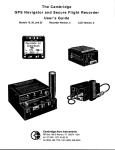
303 Navigation Display Manual
302 DDV Version 2.6
303-NAV Version 0.0.2
Firmware by Phil Schlosser; text by Dave Ellis
302 DDV (Actual Size)
303-NAV (Actual Size)
Warranty
All Cambridge Aero Instruments products are guaranteed against defects for TWO
YEARS from date of original purchase, when used in gliders. The warranty is limited
to faulty workmanship and/or materials. The unit must be returned to the factory or to
an authorized repair station. This warranty is void if failure is due to accident,
mishandling, or repairs performed by unauthorized persons.
Cambridge Aero Instruments, Inc.
1565 Dancy Blvd.
Horn Lake, MS. 38637
Tel: (662) 280-7610
Fax: (662) 280-7609
www.cambridge-aero.com
Table of Contents
Section
Page #
1. Introduction
2
2. Getting Started
2.1 The Waypoint Database
2.2 The Screen Map
2.3 What the keys do.
2.4 First flight
3
3. Terminology & Glossary
3.1 Ground Track, Bearing, and Heading
3.2 Altitude, Elevation and Height
3.3 Navigation Points
3.4 Attributes
3.5 Winds
3.6 Variometer Pointer behavior
6
4. Primary Screens
9
5. Messages and Warnings
5.1 Waypoint Control Zone Messages
5.2 Warning Messages
14
6. Specifications
15
4
5
7
8
9
15
1. Introduction to the Cambridge 303 Navigation Display
This manual covers installation and operation of the Cambridge 303-NAV display.
The document is complete but concise. Do not expect to understand the entire
instrument by reading the Manual once. We suggest studying section 2, Getting
Started, and skim through the rest of the text. Fly with the 303-NAV for a while and
return to this document with specific topics in mind. At Cambridge, we listen to our
customers and fly with the instruments we build. The Cambridge 303-NAV embodies
20 years experience in design and construction of more than 5000 Variometers, Glide
Computers and GPS Flight Recorders. We trust you will enjoy flying with it as much
as we enjoy designing and building it for you.
303 NAV Manual - February, 2003 – Cambridge P/N MA-015
Page 2 of 15
The 303-NAV display works only with the Cambridge 302 Direct Digital Variometer
(DDV). Using 302 DDV sensors and computing power, the 303-NAV combines GPSbased Navigation, wind measurement, and Final Glide calculation in a single, easily
learned set of screens.
LCD screens on the Cambridge 302 DDV and 303 complement each other. The DDV
Home screen shows Altitude, Averager, MacCready setting, and Speed Commands.
The 303-NAV Home screen shows Waypoint Name, Distance-to-go, Bearing to the
Waypoint, Ground Track, and the difference between your current altitude and what
you need to land safely at that Waypoint.
The Cambridge DDV and 303-NAV depend on Global Positioning System (GPS)
signals for navigation, wind, and gliding performance measurement. When compared
with earlier Cambridge products, full GPS integration makes the instruments "cleaner"
and easier to learn. The 303-NAV is further simplified because it has only those
functions that pilots found most useful in our earlier instruments.
2. Getting Started
Refer to Section 2 & Appendix B of the Cambridge DDV Manual for installation
instructions. The 303 cable plugs into the DDV 6-pin “CAI Bus” connector.
2.1 The Waypoint Database of GPS Coordinates
Operation of the Cambridge 303 Navigation Display (303-NAV) requires a database
of Waypoints with GPS coordinates and Elevations in the 302 DDV internal memory.
Up to1500 Waypoints can be stored. Please refer to Section 4 of the 302 DDV
manual to learn how a Waypoint Database is transferred to the DDV. An excellent list
of Waypoint databases contributed by volunteers is available at:
http://acro.harvard.edu/SOARING/JL/TP
We guarantee frustration unless you have installed a Waypoint database.
2.2 The Screen Map
The bottom half of 303-NAV screens usually show Distance and Bearing to a
Waypoint, Glider Track over the ground, and an arrow showing Bearing - Track to the
Active Waypoint. The number of GPS satellites in view is also shown. The top half of
the screen shows information that depends on its position on the Screen Map shown
on the next page. Boxes show the number of times from the HOME screen that the
relevant key (UP/DOWN/LEFT/RIGHT) must be pushed to see the screen.
303 NAV Manual - February, 2003 – Cambridge P/N MA-015
Page 3 of 15
The HOME screen shows the Active Waypoint name and the difference
between your altitude and the altitude you need to land there safely.
The 303-NAV
Primary Screen Map
U2/D4
Version 2.5
September 2002
L6
L5
L4
Edit Select Wing
Polar Pilot Load
L3
Climb and Cruise
Performance numbers
Component, Vector,
and Relative Wind
U1/D5
L2
Misc.
Data
L1
HOME
Mark
Lift
R1
R2
R3
R4
R5
R6
Edit
Task
Select a Waypoint
D1/U5
Differential Altitude,
Vector & Relative Wind
D2/U4
Diff. Altitude based on
Component wind
U3/D3
Waypoint data +
GPS Ground Speed (V)
2.3 What the keys do
There are 6 keys on the 303-NAV: UP/DOWN, LEFT/RIGHT, GO, and ON.
There are three possible ways to use the keys:
Press a key for a short time
Press & hold a key for more than 1 sec. (For auto scroll, timer reset, and
OFF)
Press UP/DOWN keys more than 3 times/second to skip over Waypoints.
ON:
The ON key turns the instrument on if power is connected to DDV pin 2.
Press & Hold the ON key for more than 3 seconds to turn the DDV off.
Pressing the ON key during flight puts a Pilot Event (PEV) mark in the flight log
Pilot Name and Goal Height screens are displayed after a PEV is marked.
GO:
Pressing the GO key several times ALWAYS takes you to the HOME screen.
Press the GO key from the HOME screen to show elapsed flight time.
Press & Hold the GO key from the HOME screen to reset elapsed time.
Note: Flight time resets automatically each time you take off.
UP/DOWN from the HOME screen:
303 NAV Manual - February, 2003 – Cambridge P/N MA-015
Page 4 of 15
Scroll through 6 screens showing wind, glide altitude, and glider performance.
LEFT/RIGHT:
Screens to the RIGHT of HOME are mostly for selecting Navigation Points.
Screens to the LEFT of HOME have a variety of functions.
Except on the HOME screen, UP/DOWN keys usually:
a.
Scroll through Navigation points (RIGHT of HOME) or
b.
Scroll through Miscellaneous data (LEFT of HOME) or
c.
Scroll through letters for spelling Pilot name or
d.
Increase or decrease a number.
2.4 First Flight
Your flight will automatically be recorded, so you might as well put your name on the
flight log. In the process you will learn how to navigate the LCD display screens.
After powering up the instrument and setting the DDV Altimeter, press the LEFT
arrow key until you see the words [Select Pilot] [ 1 Pilots ]. Press GO, then press
DOWN until you see the words [New Pilot] on the screen. Press GO again. You'll
see a message [Enter Name ->] [<-Preference]. The hint is to press the RIGHT arrow
key to enter your name.
Once you press RIGHT, you will see [New ] [Pilot ]. Scroll UP or DOWN to
change the underlined character. Press RIGHT to move to the next character. Keep
moving the underline cursor. Eventually you will see a place to enter your
preferences for instrument behavior. Keep going until you see [Goal Height] [nnn
feet] Scroll UP until nnn is 1000 ft.
Press GO to exit the New Pilot entry screens. Answer Yes to the question [Save
Name?] Answer Yes to the question [Make Active?]. Press GO to take you back to
the HOME Screen. This is about as complicated as the 303-NAV gets. Please don't
be intimidated; this gadget is supposed to make glider flying more fun!
If you have a database loaded, you will see the Waypoint with the H attribute
(hopefully your gliderport!) on the 303-NAV HOME screen. When you fly, the big
arrow on the LCD screen shows the direction to turn to go back to the gliderport. The
top line on the LCD screen shows the difference between your altitude and what you
need to arrive safely back at the gliderport. As you get close to the gliderport, the
303-NAV gives you on-screen messages and audio beeps for Approach and Arrival.
It is just that simple!
From the 303-NAV HOME screen, Press GO to see the elapsed time since takeoff.
The instrument remembers flight time, so you can update your logbook after landing.
There is much, much more to the 303-NAV, but you can now fly safely with it.
Don’t look here for detailed discussion on tactics for cross-country and competitive
gliding; there are plenty of good books on those subjects.
303 NAV Manual - February, 2003 – Cambridge P/N MA-015
Page 5 of 15
3. Terminology and Glossary
Gliding is a specialized sport with its own weird terminology. Here are some words
and phrases you'll find in this Manual:
3.1
Ground Track, Bearing, and Heading
North
Waypoint, Bearing 22°
Track, 30°
Heading, 45°
Angles in this diagram are
defined relative to North.
Wind, 90°
Bearing is the angle of the line between the glider's position and the Waypoint.
Ground Track is the angle of the glider's flight path over the ground.
Heading is where the nose of the glider is pointed.
A crosswind, as shown, makes track and heading different.
3.2
Altitude, Elevation and Height
Altitude is measured relative to Mean Sea Level (MSL). The glider's Altitude is what
your Altimeter shows if MSL barometric pressure is correctly set.
Elevation: The altitude of the ground at the Waypoint.
Goal Height:
Imagine a point in the sky directly above your gliderport called the Goal Point. The
303-NAV displays the altitude you need to glide to this Goal Point in the sky. Goal
Height is typically set to 1000 feet. If your glide ends at the Goal Height, you have
enough altitude to execute a normal landing pattern.
Glide Altitude:
The 303-NAV predicts the altitude you will lose getting from your present location to
the Goal Point. If you are flying a task, the Glide Altitude is that which is
required to fly to ALL the remaining task Turnpoints. Otherwise, Glide Altitude is
that which you need to arrive safely at the Goal Point directly above the Active
Waypoint.
303 NAV Manual - February, 2003 – Cambridge P/N MA-015
Page 6 of 15
Differential Altitude Required:
The 302 DDV has a precision altimeter. The 303-NAV displays the difference
between your present Altitude and the altitude you need to glide to the Goal Point.
Differential Altitude Required is abbreviated as Diff on the 303-NAV HOME screen.
Present
Position
Goal
Point
Glide Altitude
Goal Height
Goal Elevation
Diff. = Altimeter - Glide Altitude - Goal Height - Goal Elevation
Note: Goal Height is set in Pilot Preferences (Screen L5)
3.3
Waypoints
The 303-NAV requires a database of Waypoints. These are just carefully formatted
computer text files. Each Waypoint is one line of text. Commas separate fields in the
database.
37,44:28.400N,072:40.880W,725F,T, Stowe VT
,ChurchSteepl
38,44:06.920N,072:49.820W,1470F,TAH, Sugarbush ,RW 22 NE End
39,44:24.500N,072:11.700W,1450F,T, W. Danville, Lake Narrow
1
2
3
4
5
6
7
Field #
1
2
3
4
5
6
7
Meaning
Waypoint Index #
Latitude (Degrees, decimal minutes only!) (N=North, S=South)
Longitude (W=Western Hemisphere, E=Eastern Hemisphere)
Elevation (F = Feet, M = Meters)
Attributes (Each point can have up to 6 attributes)
Waypoint Name (Up to 12 characters)
Comment Field (Up to 12 characters)
303 NAV Manual - February, 2003 – Cambridge P/N MA-015
Page 7 of 15
3.4
Attributes:
T, S, and F:
Only Waypoints having Turnpoint (T), Start (S) or Finish (F) attributes can be included
in Tasks. Also, only T, S, or F points are sorted by Spelling on screen R4 or ID# on
screen R5.
A and L:
On screen R3, Waypoints having Airport (A) or Landable (L) attributes are sorted by
distance from your current position.
H (HOME) At power-on the 303-NAV navigates to the Waypoint with the H attribute.
Active Waypoint:
The HOME screen shows the Active Waypoint name together with bearing and
distance to it.
Selected Waypoint:
Many different 303-NAV screens display lists of Waypoints. You scroll through a list
to select a Waypoint. Except when you’re editing a Task, a Selected Waypoint
becomes the Active Waypoint when the GO key is pressed.
3.5
Winds
The usefulness of information provided by the 303-NAV is enhanced because the
instrument automatically measures the wind in the airmass through which the glider is
flying. The 303-NAV uses and displays no less than 4 different kinds of wind
information:
Fast Component Wind (HW/TW):
Once per second the 303 NAV measures Indicated Airspeed (IAS), applies
corrections for Altitude and Outside Air Temperature, Calculates True Airspeed
(TAS), and computes the difference between TAS and GPS Groundspeed (GS). If
TAS greater than GS, the result is a Headwind (HW). If TAS less than GS, the result
is a Tailwind (TW). For brevity, we call this quantity HW /TW, the wind in the direction
of flight. The 303-NAV displays HW/TW as HW or TW followed by wind strength in
knots or Km/Hr.
Average HW/TW:
The glide angle with a Headwind (HW) is lower than with a tailwind (TW). The 303NAV Differential Altitude required based on Average HW/TW is shown on Screen
D2/U4. HW/TW averaged over 30 seconds is used rather than Fast HW/TW because
it makes the Differential Altitude Required (Diff.) more stable. The 303-NAV displays
Average HW/TW as Avg. HW or Avg. TW, followed by wind strength in knots or
Km/Hr.
303 NAV Manual - February, 2003 – Cambridge P/N MA-015
Page 8 of 15
Wind Direction and Strength (Vector Wind):
The 303-NAV averages HW/TW measurements made at different tracks to compute
the Vector Wind. The Vector Wind is updated only when the glider turns at least 30
degrees in a short time. Vector Wind is shown as ddd@ss (3 digits for direction and
2 digits for strength)
Relative Wind Direction:
This is the direction of the wind relative to the glider's GPS Track over the ground.
The 303-NAV displays Relative Wind as an arrow that shows graphically the
approximate direction from which the wind is blowing on the glider. This is followed by
a three-digit number that gives, precisely, wind direction relative to the glider's track.
3.6
Variometer Pointer Function
302 Variometer pointer function can be selected in screen L5 as a Pilot Preference.
The choices are:
Total Energy --- The variometer pointer shows the change in the glider's total energy.
Total Energy = Kinetic Energy (airspeed) + Potential Energy (Altitude)
Netto --- The variometer pointer shows the airmass vertical motion. This is useful in
cruise mode because positive airmass motion indicates improved glide angle, and
vice versa.
Super Netto -- The variometer pointer shows what a Total Energy variometer would
show at the glider's best glide speed. A Super-Netto variometer is sometimes known
as a Relative variometer. Most pilots prefer a Super-Netto variometer because it
gives the glider's actual climb rate in a thermal while still showing the climb rate
obtainable when slowing from fast cruising speed to thermalling speed.
Note: The DDV averager is total-energy compensated. The DDV audio is ALWAYS
configured as a Super-Netto variometer.
4. Primary Screens
Power-On Screens
Instrument firmware version and configuration are shown at power-on.
If power is already on, pressing the 303-NAV [ON] button displays Pilot Name and
Goal Height. Go to Screen L5 “Pilot Select” to change these settings.
HOME Screen
The HOME screen shows the Active Waypoint Name and the Differential Altitude
required to reach the Goal Waypoint at the Goal Height (abbreviated Diff). If you are
flying a task, the Goal Waypoint is the last Waypoint of the task. If you are not flying
a task, the Goal Waypoint is the same as the Active Waypoint.
303 NAV Manual - February, 2003 – Cambridge P/N MA-015
Page 9 of 15
The Differential Altitude required includes the altitude you would gain by slowing from
your present speed to the best glide speed (Vm). Including Kinetic Energy in the
calculation makes displayed Differential altitude independent of your cruise speed.
The large arrow shows the difference between the glider's track and the bearing to
the Active Waypoint. Turn in the direction of the arrow to fly towards the Waypoint.
The small dots at the lower right show the number of GPS satellites being used to
determine your position. With a good antenna location, you should see 5-8 dots.
RIGHT of the HOME Screen
R1 -- Last Point
15 Recent Active Waypoints and Lift Points are listed here. The most recent point
[Last Point] is at the top of the list. Scroll DOWN to see earlier points. Lift Points (See
screen L1) are “Named” by time and lift strength. Press GO to make a Waypoint or
Lift Point Active and return to the HOME screen.
R2 -- Task Turnpoint
If a Task Turnpoint List has been created (see Screen R6), screen R2 shows
[Task off] ["Point 0"]. Press the UP key to see [Start This] [Task]. Press GO to start
the task. The Start point (Point 0) becomes the Active Waypoint.
Once a task has been started, R2 shows the next Task Turnpoint. Press GO to make
this Turnpoint Active. Use UP/DOWN keys to review task Turnpoints and Stop, Start,
or Resume a task.
If you make an off-task Waypoint Active, the R2 screen shows [Resume Task]
["Current Point #"]. Press GO to make the current Task Turnpoint active.
R3 - Landable Waypoints by distance from current position
The closest Landable Waypoint (L or A attribute) is shown. Use the DOWN key to
see other points sorted by increasing distance. Differential Altitude required to reach
the Landable Waypoint is shown at the upper right. Differential Altitude required (Dif)
is computed using Vector Wind and current MacCready setting.
R4 - Turnpoints sorted by Alphabetic Spelling
The DOWN key scrolls A -> Z. The UP key scrolls Z -> A. Press and hold the key to
scroll through the Turnpoints. Tap either key more than 3 times/sec to skip over 10
Turnpoints.
R5 - Turnpoints sorted by ID#
Waypoints with T, S, or F attributes are sorted by their numeric ID#. Tap the UP or
DOWN key more than 3 times/second to skip over 10 Turnpoints.
303 NAV Manual - February, 2003 – Cambridge P/N MA-015
Page 10 of 15
R6 - Edit Task
This is where you edit Turnpoint lists for Tasks and Declarations. Lists are managed
in R2. Press GO to see the list from which you can select T P #0. Press DOWN to
scroll through the Turnpoint list by ID# to the one you want for the starting point of
your task. Press RIGHT to see the list for the first task Turnpoint. Continue until you
have completed the task, including the finish point. The number at the bottom of R6 is
the total distance from Task Point #0 to the currently selected Turnpoint.
Don’t press GO until you are done making the list! If you answer YES to the question
[Declare Task], the list + date & time will be declared in the next flight log. If you
answer YES to the question [Save Changes], a new Task or edited Task will be
saved. Otherwise, the pre-change Task is retained.
[End of Task] is displayed between the first and last Turnpoint in the Database. To
make a null task (no points); select [End of Task] as Point #0. To delete a
Declaration, you must declare a null Task. A non-deleted Declaration automatically
appears as a default task. This makes it hard to accidentally delete a Declaration.
R6 can also be used to select, from a large Waypoint database, a short list of
Turnpoints points relevant to a recreational flight for the day. R2 becomes just a
short list from which you can select a Turnpoint without declaring or starting a task.
We have done our best to make creating, editing, and stepping through a Task
simple and intuitive. You are probably thinking -- “Surely you jest, sire!!”
Please, please, practice this stuff on the ground before committing aviation!
LEFT of the HOME Screen
L1 -- Mark Lift
Press GO to mark your current position and altitude. The Lift Point becomes Active on
the HOME screen. Use R1 to toggle between a Lift Point and another point. Lift
Points go away when the instrument is turned off.
Note: Diff. Altitude to a marked point includes Goal Height (see Section 3.2).
L2 -- GPS and other Data
The first L2 screen shows current position GPS Latitude
Scroll down to see:
GPS Longitude
GPS Altitude
Pressure Altitude (Assumes Barometric pressure = 1013.2 mbar or 29.92" H20)
Engine Noise Level (ENL) (Range 0 - 999, Engine ON at 500+)
(Note: ENL responds to audio sounds from the internal speaker!
Instruments approved for motorglider must use an external audio speaker.)
EPE (Estimated Position Error)
UTC Date (Month/Day/Year)
UTC (Universal Time Coordinated = time in Greenwich, England)
303 NAV Manual - February, 2003 – Cambridge P/N MA-015
Page 11 of 15
L3 -- GPS Satellite Signal data
The upper line shows No, 2D, or 3D GPS fix, & # of satellites used/in view.
The lower line shows the satellite ID# and Signal-to-Noise Ratio (SNR)
The lower left digit shows satellite angle (from North) and azimuth.
Press DOWN key to see data from each in-view satellite.
(SNR should be above 50 for at least one satellite. Check antenna location if this is
not the case. Only satellites with SNR greater than 35 are used for navigation.)
This stuff keeps designers and other geeks happy.
L4 -- Water Ballast and Wing Loading
The upper line shows water ballast as a % of the maximum entered as part of the
polar data. Press UP or DOWN keys to change %. The number shown at the lower
left is the Wing Loading in units specified on the second line of the screen
L5 -- Select Pilot
Press GO in the Primary screen to see the first pilot.
Press DOWN to scroll through the list of pilot names.
The Last entry in the Pilot Name list is [New Pilot ?]
Press GO to select a pilot.
The next Screen reminds you to press -> to edit Name, <- to edit Preferences.
Enter a pilot’s name by scrolling through the alphabet for each character in the name.
The pilot’s first and last name can be up to 12 characters long.
Preferences can be selected for the following quantities:
Units of altitude, airspeed, distance, climb rate, and temperature
Goal Height and speed-to-fly error threshold for audio warning.
Radius at which “Approaching” and “Arrival!” warnings are given. (Section 5.1)
Audio sink tone in Climb mode? [YES or NO]
Choice of Variometer pointer behavior (Section 3.6)
Pilot name and Preferences are stored when the GO button is pressed.
L6 -- Edit Polar
This is useful if your glider has 2 possible wingspans, and therefore 2 different polars.
See the Utility Program Section in the 302 DDV Manual for definitions. Press GO to
store the new polar and return to the HOME screen.
Note: Polar can’t be changed if Utility program Configuration Lock is ON.
UP or DOWN from the HOME Screen
A cross-country gliding flight has several phases. Data displayed for inter-thermal
flight may not be very useful for the final glide. Ridge soaring is a special situation for
which the Fast component wind is useful. Flying in mountain wave also presents
unique challenges. Sometimes during cruise you may wish to know the average
airmass motion (Average Netto) or the glider's effective L/D. We could present ALL
the information ALL the time, but the LCD screen would be filled with a jumble of tiny,
confusing numbers.
303 NAV Manual - February, 2003 – Cambridge P/N MA-015
Page 12 of 15
Cambridge has a different way of presenting a large amount of data. We have
arranged the 303-NAV screens UP and DOWN from HOME so each screen is
appropriate for a particular gliding situation. Each screen shows the big GPS
Navigation Arrow, so you always know how to turn towards the Active Waypoint. GPS
Ground Track and Distance & Bearing to the Active Waypoint are also shown on
each of these screens. As with all other 303-NAV screens, pressing GO returns
HOME from any of these screens. It’s easy to navigate both glider and instrument
back HOME. :-)
U1/D5 -- Three flavors of Wind!
You get here by pressing UP once (smart!) or DOWN 5 times (dumb!). The upper line
shows the Fast Component Wind (HW/TW). It updates every second. Watch it. You
will learn a lot about thermal, ridge, and wave lift if you observe the associated wind
patterns.
The lower line shows Vector Wind and the relationship of this wind to the glider's
track over the ground. The small arrow shows the direction from which the wind is
coming relative to the glider’s Track over the ground. We call this the Relative Wind.
The number to the right of the arrow is the precise wind direction relative to the
glider’s track. 180 means a pure tailwind. Observing Relative Wind helps you
understand cloud streets and convergence zones.
U2/D4 -- Climb and Cruise Performance numbers
This is a collection of numbers that measure your gliding performance. The upper left
number is the average climb rate since the beginning of circling flight. When the 30
second climb average (shown on the DDV) falls below this number, experienced
cross-country pilots leave a thermal and cruise to the next one.
The upper right number is the effective glide angle (L/D). This is computed as GPS
ground speed divided by the glider's climb rate. Upwind flight will show a lower
effective glide angle than downwind flight. As with other performance numbers, the
effective glide angle is averaged over 30 seconds.
Netto is variometer reading + glider sink rate as determined from the polar. Netto
represents airmass vertical motion. The lower line on this screen shows Netto
averaged over the last 30 seconds. This is useful during the final glide as it shows
whether or not you are beating the glide computer's estimate of altitude required to
reach the goal point.
D1/U5 -- Differential Altitude Required, Vector and Relative Wind
This screen may be useful on a final glide because it combines Relative Wind and the
altitude required for the glide.
D2/U4 -- Differential Altitude Required based on Averaged Component Wind
This screen is useful on long, straight final glides. Due to friction, winds aloft are
stronger than winds near the earth's surface. Vector Wind obtained by circling at high
altitude does not update during straight flight towards the finish line. The Average
Component wind is updated during straight flight, and is therefore better than Vector
Wind under this special circumstance.
303 NAV Manual - February, 2003 – Cambridge P/N MA-015
Page 13 of 15
D3/U3 -- Waypoint Information & Ground Speed
This screen is useful in two rare situations. This is why it is equally accessible with
UP or DOWN keys. The first case is when you are about to land off-field. If you are
lucky, the Waypoint database will include information on preferred landing direction,
tower frequency, or other useful information. The second case is in wave flying
conditions where the headwind may exceed the glider's true airspeed. Component
wind data is useless when this happens. Looking at GPS Ground Speed (V) helps
you figure out what the heck is going on!
5. Messages and Warnings
5.1 Waypoint Control Zone Messages
The 303-NAV defines two circles around the Active Waypoint. Preference for the
radius of each circle can be set differently for each pilot. The “Approaching” radius
defaults to 3 Km (~1.6 NMi). The “Arrival” radius defaults to 0.5 Km (~0.27 NMi).
When the glider moves from outside to inside the “Approaching” radius, the DDV
makes 2 short, loud beeps, and the message “Approaching” is displayed for a few
seconds on the HOME screen. On other screens, the “M” (Message) annunciator is
lit. When you press GO, the 303-NAV jumps to the HOME screen and shows the
message.
When the glider moves from outside to inside the “Arrival” radius, the DDV makes one
long, loud beep and the message “Arrival” is displayed for a few seconds.
“Approaching”
“FAI Sector”
Task Course Lines
“Arrival”
303 NAV Manual - February, 2003 – Cambridge P/N MA-015
Page 14 of 15
If a Task is active, the 303-NAV gives an additional message when the glider enters
the FAI Photo Sector for the Active Task Turnpoint. Three loud, short beeps are
accompanied by the message “In Sector” on the 303 HOME screen. The “In Sector”
message takes priority over both the “Approaching” and “Arrival!” messages. The
outer boundary of the DDV “FAI Sector” is at the “Approaching” radius.
5.2 Warning Messages
The Cambridge 300 system provides audio warning beeps for potentially dangerous
situations. Please see the DDV Manual for installation of the necessary switches,
operational details, and description of audio sounds. The 303-NAV provides warning
messages that appear on all screens and persist as long as a situation persists.
Normally, the message is canceled when the pilot takes corrective action. However,
each warning sound and message may also be canceled by pressing the 303 GO key
or the DDV control knob.
If Airbrakes are open as the glider reaches takeoff airspeed, the message [Close]
[Airbrakes!] is shown.
If Airbrakes are opened during flight, and the landing gear has not been extended, the
message [Extend] [Landing Gear] is shown.
If airspeed falls below the threshold set on DDV Screen #8, the message
[Airspeed] [Too Low!] is shown.
6. Specifications
Size:
66 x 66 mm (2.6” x 2.6”) square. 14 mm (0.55”) behind panel
Mounts in 57 mm (2.25”) round hole
Weight:
85 grams (3 oz.)
Power:
20 ma at +5 Volts (0.1 watt)
Connection:
6-conductor modular cable with RJ-11 connector
(Cambridge Data Bus, I^2C @ 150 Kbit/sec)
Database:
Up to 1500 Navigation Points
303 NAV Manual - February, 2003 – Cambridge P/N MA-015
Page 15 of 15