1
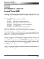
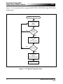
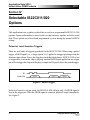
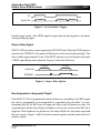
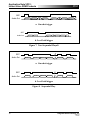
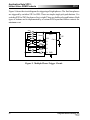
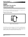
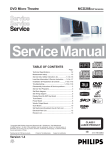
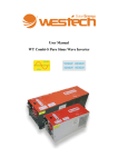
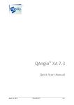
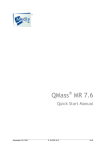
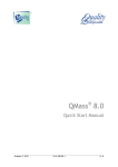
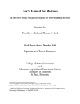
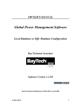
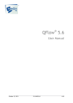
Application Note VP01:
Instant Voice ROM Products
ISSI
ISSI
®
®
Integrated Silicon Solution, Inc.
Application Note VP01:
INTRODUCTION
to ISSI's
INSTANT VOICE ROM
PRODUCTS
DECEMBER 1997
Integrated Silicon Solution, Inc.
VP005-1E
12/10/97
1
Application Note VP01:
Instant Voice ROM Products
ISSI
Section I.
Introduction ............................................................................. 53
Section II.
IVR Features ............................................................................ 55
Section III.
IVR Development Tools .......................................................... 58
Section IV.
IS22C011/020 Selectable Options ........................................... 64
Section V.
Multiple Segment Programming ............................................. 68
Section VI.
IVR Applications ..................................................................... 71
®
Section VII. PC Board Layout ..................................................................... 75
2
Integrated Silicon Solution, Inc.
VP005-1E
12/10/97
Application Note VP01:
Instant Voice ROM Products
ISSI
®
Section I
Introduction to ISSI’s
Instant Voice ROM
INTRODUCTION
Instant Voice ROMs, IVRs, are specialty devices for storing and playing sound. IVRs
utilize ISSI’s EPROM technology together with sound synthesis and D/A technology to
make instant sound storing and playing possible. The ISSI IVR products contain an
EPROM, ADPCM sound decoder, and an A/D circuit. Users first prepare an 8-bit PCM
sound file and then use the ISSI IVR development system to do the ADPCM encoding.
The encoded data is programmed into a IVR device by using our IVR writer. The sound
is ready to be played back from the IVR through either a speaker or buzzer.
IVRs Compared to Mask Programmed Voice ROM
Conventional voice ROM utilizes mask ROM technology to store sound data. A
semiconductor manufacturing photo mask corresponding to the sound data has to be
made. With this mask, the sound data can be permanently programmed to the memory
during wafer fabrication. It is this requirement of mask making and wafer fabrication that
makes the mask ROM approach inflexible.
Mask making and wafer fabrication are both time consuming. Normally, it takes several
weeks to get the first masked devices ready for delivery. The cost of making this special
mask is always (directly or indirectly) paid by customer, and is the so called NonRefundable Engineering (NRE) charge for making a particular sound code. There is also
a Minimum Order Quantity (MOQ) requirement because each wafer fabrication house
has its minimum manufacturing lot size. MOQ may vary from one company to another,
but normally it is around 10K for each sound code.
Integrated Silicon Solution, Inc.
VP005-1E
12/10/97
3
Application Note VP01:
Instant Voice ROM Products
ISSI
®
IVR on the other hand, does not suffer from these drawbacks of sound ROMs. First, the
IVR is based on OTP EPROM technology. Sound data is programmed into the memory
by an electrical signal, so no special, expensive optical mask is needed. Also, users can
quickly generate and program sound data using one of our user-friendly development
systems within their own factory. ISSI has available all the tools needed to support either
one piece programming or mass production programming, so there is no MOQ requirement.
IVRs Compared to Single Chip Record-and-Playback Sound
A single chip record-and-playback sound IC consists of a built-in microphone amplifier,
filters, A/D, D/A, and a power amplifier to drive a speaker. EEPROM or SRAM is the
normally memory for sound data storage, with some being on-chip memory and some
external memory.
To record sound, the chips must include many analog circuits, e.g., A/D, filter and
microphone preamplifier, as well as memory. Cost is high for such integration. Of course,
if you really want a single chip to do sound record and playback, you have to choose this
high-priced part. However, in many applications, users only want to record into the chip
once, and never want it to be changed. For such applications, choosing record and
playback chips still requires the user to pay for those unused analog circuits.
With IVR and our Stand-alone Record And Playback Programmer, no computer is
required. The user can record sound similarly to a single-chip record and playback sound
chip using a small writer board (one of the ISSI’s IVR support tools). To program the IVR,
you just record sound in the writer board using a microphone, then simply press a button
and the sound you recorded will be programmed into the IVR. Once programmed, the
data can never be lost or overwritten.
4
Integrated Silicon Solution, Inc.
VP005-1E
12/10/97
Application Note VP01:
Instant Voice ROM Products
ISSI
®
Section II
Features of the
Instant Voice ROM (IVR)
Very Good Sound Quality
ISSI’s proprietary ADPCM algorithm is used for sound data encoding and compression.
Each 8-bit PCM file is compressed into 4-bit data to be stored. It is decoded back to
8-bit sound data by the IVR during playback. The sound quality therefore is much better
than the 4- or 5-bit PCM, which is used in most sound products today.
User Friendly Development Tools
The IVR is most often programmed by the user, so ISSI provides a full set of development
tools. We have both Personal Computer (PC) based and stand-alone types of development systems.
The PC based sound editing system is the most complete development system for ISSI
IVRs. It consists of a user supplied sound system, a PC compatible sound card, and the
ISSI IVR programmer board. There are two types of programmer boards. One is a single
piece writer which can program one device at a time. This programmer is suitable for
sample or master making. Another is a multiple programmer board which can program
up to 20 pieces and is designed for small quantity programming. System software is
provided for device programming. Please refer to the PC Based Programming System
(IS22VP003/004/006) User's Manual for details.
There are several types of stand-alone programmer boards and each work without a PC.
A DC power supply is the only requirement for these programmers. To facilitate user
mass programming, an IVR copier is used to copy data from a programmed master IVR
to as many as eight blank IVRs.
Integrated Silicon Solution, Inc.
VP005-1E
12/10/97
5
Application Note VP01:
Instant Voice ROM Products
ISSI
®
ISSI offers a stand-alone record and playback IVR programmer board with a built-in
microphone and preamplifier. The sound is first recorded into an on-board SRAM. After
listening to and approving the recorded sound, the board does the ADPCM encoding and
programs the data into a blank IVR. Therefore, the user can record and program the IVR
without using a PC.
Flexible Phrases
Each IVR has a fixed memory size and the memory can be divided into as many as eight
separate phrases. The length of each phrase is user programmable, and the only
restriction is that the total length of all phrases shall not exceed the maximum capacity
of the IVR.
The capacity of each IVR depends not only on the memory size, but also on the sampling
rate used to record the sound. For example, the IS22C011 has 256K bits of memory. If
the sampling rate is 8000 Hz, the maximum length is eight seconds. If the sampling rate
is 6000 Hz, the maximum length is ten seconds.
Stable Built-in Oscillator
The sampling rate of each IVR is set by a very stable built-in oscillator controlled by an
external resistor. For the IS22C011, a 2 MΩ resistor will set the sampling frequency at
approximately 8000 Hz. Therefore, the sampling rate setting is very simple.
The built-in oscillator is specially designed for high stability. The oscillator frequency
remains constant at all supply voltages within the allowable range of the product
specification. As a result, the sound quality will not decay as the battery voltage falls off
with use.
6
Integrated Silicon Solution, Inc.
VP005-1E
12/10/97
Application Note VP01:
Instant Voice ROM Products
ISSI
®
User Programmable Options
Each IVR can be user programmed with different options. During ADPCM coding, the
software will merge the option information with the sound data. With this feature, the
user can try different options quickly and easily. For the type of available options, please
consult the device data sheet or the Selectable Option Section of this application note
(page 64).
Wide Supply Voltage Range and Power Saving
IVRs utilize CMOS technology, so a single power supply from 2.4V to 6.0V is allowed.
After sound playback, the chip will power down automatically and enter the standby
mode requiring very low current. Even a ‘coin cell’ can supply power to the IVR for some
time making many small and compact applications possible.
Direct LED Drive
There are two output pins designed to directly drive a single LED. If more than two LEDs
or higher power lamps are used, an external transistor can be added.
Current Mode D/A Output
Current mode D/A output, COUT, makes it easy to drive a speaker with as little interface
circuitry as a simple low cost NPN transistor. No complex filtering or amplifier circuit
is necessary. Adding a filter and power amplifier to this output gives a higher quality
playback sound.
PWM Voltage Output
To extend the range of applications, a pair of PWM output pins, VOUT1 and VOUT2, will
directly drive a speed grade “buzzer”. Sound quality is comparable to a speaker but the
power consumption is much lower. With a buzzer as the output, the user can make a very
thin sound module, with very low power consumption.
Integrated Silicon Solution, Inc.
VP005-1E
12/10/97
7
Application Note VP01:
Instant Voice ROM Products
ISSI
®
Section III
Development Tools For
Instant Voice ROM
ISSI provides a series of support tools to program or playback sound from the IVR. This
section will help the user decide which tool is most suitable for each particular situation.
The following IVR development tools are available:
IS22VP001 Playback demonstration board
IS22VP002 Stand-alone record and playback board
IS22VP003 PC based 1-piece ISA slot add-in programmer
IS22VP004 PC based 20-piece ISA slot add-in programmer
IS22VP005 1-to-8 copier board
IS22VP006 PC based 1-piece printer port programmer
IS22VP003, IS22VP004, and IS22VP006 PC-Based Programmers
IS22VP003, IS22VP004, and IS22VP006 are PC based sound recording and editing
systems. These systems are usually used when high-quality sound is required, and the
sound source is a cassette tape, CD, or DAT tape.
The IS22VP003 and IS22VP004 programmers consist of a PC add-in card and a writer
board. The IS22VP003 programs one DIP packaged IVR chip each program cycle and
it is suitable for making a master sample. The IS22VP004 can program from one up to
a maximum of 20 DIP packaged chips at the same time and is suitable for in-house small
volume production. Cost is another consideration. The IS22VP003 is less expensive than
the IS22VP004. Other ISSI programmers are available for mass production.
The IS22VP006 interfaces with the PC through the printer port and the keyboard socket
and performs like other programmers.
8
Integrated Silicon Solution, Inc.
VP005-1E
12/10/97
Application Note VP01:
Instant Voice ROM Products
ISSI
®
To use any of the programmers, the user should install a sound system with equipment
suitable to playback the sound source. A preamplifier and equalizer are recommended for
better sound quality. In order to record the sound into the computer, a sound card must
be installed. Testing has shown that the Creative Lab Sound Blaster™ card (8 or 16 bits)
is compatible with our hardware and software. Finally, either the IS22VP003 or
IS22VP004 card should be installed in the computer or the IS22VP006 connected to the
appropriate port. For detailed installation information, please refer to the PC Based
Programming System User's Manual for details.
Figure 1 shows the hardware configuration of a PC based editing and programming
system.
286/386/486
Computer
20-piece
Writer
Figure 1. PC Based Editing and Programming System.
The sound is recorded by the sound card and becomes a file stored in the computer. After
editing the sound, the user can call up the ISSI IVR sound compression software for
ADPCM coding and compression. Programmable features of the IVR most suitable for
each application are selected at this time. The ADPCM coding program produces an
encoded sound file containing sound and option information. This file can then be
programmed into the IVR. Either the IS22VP003, IS22VP004, or IS22VP006 programmer can be used to program the chip.
Integrated Silicon Solution, Inc.
VP005-1E
12/10/97
9
Application Note VP01:
Instant Voice ROM Products
ISSI
®
Figure 2 is the production flow using the IS22VP003, IS22VP004, and IS22VP006
programmers.
Cassette, Tape, DAT, CD
Voice Recording
and
Editing
NO
Accept
Quality?
YES
Option Select
and
ADPCM Coding
NO
Successful?
YES
Programming
Using
IS22VP003/004/006
Programmed IVR
Figure 2. PC Based Production Flow.
10
Integrated Silicon Solution, Inc.
VP005-1E
12/10/97
Application Note VP01:
Instant Voice ROM Products
ISSI
®
IVR Copiers
IVR copiers are single board IVR programmers which work without a PC. They need
only a 15V DC power supply and copy sound data from a programmed master IVR chip
to blank IVR chips. Users can make a master IVR from the PC based programmers. The
1-to-8 copier (IS22VP005) can copy data from the master to a maximum of eight blank
IVR chips simultaneously and is a low cost system for programming DIP packaged IVRs.
Mass production can be done by using this copier board to program up to eight blank
chips at a time, and more copiers can be employed for larger volumes.
A 1-to-1 IVR copier is available on special order and is designed to program only one
chip at a time. This is suitable for COB (chip on board) assembly programming. As each
chip is bonded to the PC board, it can be programmed prior to encapsulation. Figure 3
shows a flow for programming IVR chips during COB manufacturing.
Integrated Silicon Solution, Inc.
VP005-1E
12/10/97
11
Application Note VP01:
Instant Voice ROM Products
ISSI
®
Blank IVR
Die Attach
and
Bonding
Master IVR
1-to-1
Programming
UV Erase
NO
Verify OK?
YES
Encapsulation
Final Test
Finished COB
Figure 3. COB Programming Flow Using an ISSI IVR Copier.
COB is a low cost packaging alternative for low end products. IVR users can order blank
die and have a COB bonding house do the packaging and test. As in Figure 3, the blank
IVR is attached to the substrate and bonded to a custom made PCB. A test jig, with a cable
connection to the IVR copier socket, is used to transfer encoded sound data from the
master to the die on the PCB. If the programming is successful, the COB is then
encapsulated. Otherwise, the COB should be examined and, if necessary be UV erased
(contact ISSI for special instructions concerning UV erase) and reworked. Please note
12
Integrated Silicon Solution, Inc.
VP005-1E
12/10/97
Application Note VP01:
Instant Voice ROM Products
ISSI
®
that in order to be UV erasable, the working environment should be very clean. Dust on
the memory area of the chip will cover some memory cells and block the UV light and
stop erasure.
Using the ISSI copier, low cost in-house mass programming is possible. Production
volume is very flexible and totally controlled by the users. Delivery, of course, is not a
problem once the users have a stock of blank IVRs.
Large Volume IVR Programming
If a particular sound is to be programmed in a quantity of more than a few thousands, it
may be more economical to purchase pre-programmed IVRs. ISSI offers a factory
programming solution for high-volume production so that during wafer testing, the
sound data (which was submitted to ISSI and approved by the customer), will be
programmed onto the IVR. The shipped devices will be die with sound data preprogrammed, which is very similar to buying a sound ROM. However, there is no NRE
charge and no long lead time. The quantity will be a multiple of the number of good die
per wafer so there is no MOQ issue.
IVR Standalone Record and Playback Programmer
The ISSI IS22VP002 programmer board can record, playback, and program IVR chips
without requiring a PC. Sound can be directed to the on-board microphone, recorded into
on-board SRAM, and played back through the on-board speaker. If the sound is
acceptable, a blank IVR is programmed with the sound stored in the on-board SRAM.
This programmer demonstrates the OTP instant recording capability of the IVR. With
this writer, a user can program IVRs similarly to single chip record and playback ICs.
This concept is particular useful in the personalized greeting cards, gifts, and similar
markets. Since most applications have different requirements, our application engineers
can work with customers to develop custom programs.
Integrated Silicon Solution, Inc.
VP005-1E
12/10/97
13
Application Note VP01:
Instant Voice ROM Products
ISSI
®
Section IV
Selectable IS22C011/020
Options
This application note explains in detail the several user programmable IS22C011/020
options. Option information is stored in the on-chip memory together with the sound
data. These options are selected and programmed by users during the normal ADPCM
coding.
Pulsed or Level Sensitive Triggers
There are two kinds of triggering methods for the IS22C011/020. When using a pulsed
trigger, a HIGH signal (i.e., voltage equals VCC) applied to a trigger pin longer than the
debounce time (about 30 ms), the chip plays back the whole phrase. IS22C011/020 is not
re-triggerable, so when the chip is playing, another HIGH signal applied on any trigger
pin will not trigger the chip until the play is completed. Figure 4 shows the pulsed trigger.
S1
Audio Out
Phrase 1
Phrase 1
Phrase 1
Figure 4. Pulsed Trigger.
In the level sensitive trigger mode, the IS22C011/020 will play only if a HIGH signal is
kept at the trigger pin. Once the HIGH signal is removed, playback stops immediately.
See Figure 5.
14
Integrated Silicon Solution, Inc.
VP005-1E
12/10/97
Application Note VP01:
Instant Voice ROM Products
ISSI
®
S1
Phrase 1
Audio Out
Phrase 1
Phrase 1
Figure 5. Level Sensitive Trigger.
In both trigger modes, if the HIGH signal is longer than the playing phrase, the phrase
will repeat playing again.
Stop or Busy Signal
IS22C011/020 provides a status signal on the STP/BUSY pin. When the STOP option is
selected, the STP/BUSY will output a HIGH pulse at the end of audio playback. The
pulse width is approximately 30 ms. If the BUSY option is selected, the pin will output
a HIGH signal during audio playback. Figure 6 shows the difference.
Stop Option
Busy Option
Audio Out
STP/BUSY
Figure 6. Stop or Busy Option.
Non-Sequential or Sequential Playall
If the IS22C011/020 is programmed with more than one sound phrase, the SBT trigger
pin can be programmed in non-sequential or sequential play-all modes. For nonsequential play-all, the SBT pin will trigger the chip to play all phrases in order. For
sequential play-all, the chip will play each phrase, one by one, whenever the SBT pin is
triggered. After all phrases are played once, the chip will play the first phrase again and
the cycle repeats. Figures 7 and 8 show these options together with the pulsed and level
sensitive option.
Integrated Silicon Solution, Inc.
VP005-1E
12/10/97
15
Application Note VP01:
Instant Voice ROM Products
ISSI
®
SBT
Audio Out
Phrase 1
Phrase 2
Phrase N
Phrase 1
Phrase N
Phrase 1
a. One shot trigger
SBT
Audio Out
Phrase 1
Phrase 2
Phrase 1
Phrase N
Phrase 1
b. Level hold trigger
Figure 7. Non-Sequential Playall.
SBT
Audio Out
Phrase 1
Phrase 2
Phrase 2
Phrase 2
Phrase N
Phrase 1
Phrase N
Phrase 1
a. One shot trigger
SBT
Audio Out
Phrase 1
Phrase 2
Phrase 2
Phrase 2
b. Level hold trigger
Figure 8. Sequential Play.
16
Integrated Silicon Solution, Inc.
VP005-1E
12/10/97
Application Note VP01:
Instant Voice ROM Products
ISSI
®
Ramp-Up and Ramp-Down Options
The Ramp-Up/Down option affects only the speaker drive output (COUT) pin and will
not affect the PWM buzzer driving VOUT1 and VOUT2 pins. Since each IVR chip will
automatically power down after playback, current output from COUT will drop from a
certain value to zero. If the current drops suddenly, a ‘pop’ sound will be heard through
the speaker. To reduce this ‘pop’ noise, a smooth current ramp down circuit is used by
the IVR. Instead of suddenly dropping, the current will gradually decrease to zero.
Options Setting
All options are set during ADPCM coding, which is done with the PC based voice
programming system software. The ACODING command is accessed by pressing the
letter ‘A’. After entering the number of sound phrases and the name of the file to be
encoded, the software will ask you to select options by answering ‘yes’ or ‘no’. The
option data will be merged with sound data to form a data file which is ready for IVR
programming. After each ADPCM encoding, a file with .LOG extension will be created
and it contains all the information including the sound file name for each phrase and the
option setting information.
Integrated Silicon Solution, Inc.
VP005-1E
12/10/97
17
Application Note VP01:
Instant Voice ROM Products
ISSI
®
Section V
Multiple Phrase Programming
For the IS22C011/020
As indicated in the product specifications, ISSI IVRs can be programmed into multiple
sound phrases. Up to eight phrases can be programmed into a single IS22C011/020
device. The time duration of each phrase is not fixed but the total time must not exceed
the total time the chip can support, i.e., eight seconds for 8 KHz sampling.
Multiple Phrase Encoding
Separate sound files for each phrase in .VOC format should be prepared. The sound files
are merged together with option information during ADPCM encoding. The ADPCM
encoding is started by selecting the ACODING sub-command 'A'. The number of phrases
will be asked for. Type in the number of sound files to be programmed into the
IS22C011/020 device. After reading the number, the file names will be requested. Type
in the sound files you have edited, but do not use the “.VOC” extension. The software
will then ask for option information and simply answer ‘yes’ or ‘no’ to set each option.
The ADPCM encoding software will merge all the sound files and option information to
form a new data file with the extension “.DPM” which is then ready for programming
into the IS22C011/020 device. After each ADPCM encoding, a log file with a .LOG
extension will be generated which records the information for ADPCM encoding,
including a sound file for each phrase, the option settings, the start and end address of
each phrase, etc.
18
Integrated Silicon Solution, Inc.
VP005-1E
12/10/97
Application Note VP01:
Instant Voice ROM Products
ISSI
®
Several new files are generated after ADPCM encoding. They are listed below:
• filename.DPM - encoded sound data and option information to be written into the
IVR chip.
• filename.LOG - log file with the details of the .DPM sound data file.
• filename.QAN - emulation of compressed sound in the .VOC format. The user can
listen to this file and hear the sound which is very similar to the
chip’s output.
Playback of Multiple Phrase
Sound playback is triggered by applying a HIGH signal (i.e., voltage = VCC) to the four
triggering pins S1, S2, S3, and S4. Up to eight phrases can be stored in the chip. These
are triggered by four pins, and the table below shows the coding required to trigger each
phrase.
Phrase
one
two
three
four
five
six
seven
eight
Integrated Silicon Solution, Inc.
VP005-1E
12/10/97
Trigger Pin
S1
S2
S3
S4
S1 and S2
S2 and S3
S3 and S4
S1 and S4
19
Application Note VP01:
Instant Voice ROM Products
ISSI
®
Figure 9 shows the circuit diagram for triggering all eight phrases. The first four phrases
are triggered by switches SW1 to SW4. These are simple single pole push buttons. Use
switches SW5 to SW8 for phrases five to eight. These are double pole push buttons. Both
types of buttons can be implemented by a custom PCB layout and rubber contacts for
minimum cost.
SW8
VCC
ROSC
SW5
SW1
SW6
SP
OSC
S1
COUT
SW2
S2
SW7
SW3
SW4
S3
S4 GND
Figure 9. Multiple Phrase Trigger Circuit.
20
Integrated Silicon Solution, Inc.
VP005-1E
12/10/97
Application Note VP01:
Instant Voice ROM Products
ISSI
®
Section VI
Application Circuits For
Instant Sound ROM
IVR series of devices are designed for a wide range of applications. This application note
gives some examples of circuits for different applications.
Playback Using Piezo Buzzer
4.5V
ROSC
VCC
VOUT1
OSC
VOUT2
S1
S2
S3
S4
SBT
IRP
PIEZO
BUZZER
GND
Figure 10. Direct Drive Buzzer.
Each IVR offers a pair of buzzer driving pins, VOUT1 and VOUT2, which directly drive
a piezo buzzer. Since a buzzer is a voltage driven device, VCC should be at least 4.5V for
acceptable loudness. Buzzers used should be the double sided, sound grade ‘Piezo
Speaker’ types. Buzzers are normally not suitable for melody sounds.
Integrated Silicon Solution, Inc.
VP005-1E
12/10/97
21
Application Note VP01:
Instant Voice ROM Products
ISSI
®
The advantage of using a buzzer is that the thickness of the playback module can be
extremely small and hence is suitable for greeting card type applications. Also, buzzers
require very little power, usually only a very few milliamps (typically 20 mA). A ‘Coin
Cell’ battery is usually powerful enough for most applications. The only drawback is the
relatively low sound volume from a buzzer when compared to a speaker. However,
optimum buzzer mounting and casing can increase sound volume.
Playback With Single Transistor
The COUT audio pin is specially designed for driving speakers through an NPN
transistor. The output current is biased for 3V applications. Figure 11 shows the circuit
for a single transistor output.
3.0V
VCC
ROSC
SP
OSC
S1
S2
S3
S4
SBT
IRP
COUT
8050C
GND
Figure 11. Single Transistor Playback.
22
Integrated Silicon Solution, Inc.
VP005-1E
12/10/97
Application Note VP01:
Instant Voice ROM Products
ISSI
®
For supply voltages larger than 3.0V, an additional base resistor RB should be added to
the base of the transistor. RB should be from 190 to 470 Ohms depending on the VCC value
and the sound volume required.
VCC > 3.0V
VCC
ROSC
SP
OSC
S1
S2
S3
S4
SBT
IRP
COUT
RB
8050C
GND
Figure 12. Single Transistor Playback Circuit for VCC > 3.0V.
Figure 13 shows the circuitry for applications that require immediate Stop Play of
current section triggered, allowing Start Play of next section triggered. This circuitry
can only be applied to S1 through S4 and must be applied to each pin individually.
VCC
SP
OSC
100Ω
COUT
8050C
S1-S4
1µf
IRP
GND
Figure 13. Stop-Start Triggering Circuit
Integrated Silicon Solution, Inc.
VP005-1E
12/10/97
23
Application Note VP01:
Instant Voice ROM Products
ISSI
®
Section VII
Example PC Board Layout
This example PC board demonstrates how to playback with ISSI’s voice chips. It
supports three different modes of playback: Buzzer, Transistor and Power Amplifier.
To hear playback through a buzzer, simply plug a double side buzzer into the JP2
output port.
To hear playback through a transistor, the JP4 jumper should be plugged to the TX
side and an 8Ohm speaker should be connected to the JP1 jack.
To hear playback through an operation amplifier, the JP4 jumper should be plugged
to the AMP side and an 8Ohm speaker should be connected to the JP5 jack.
A 4.5V DC power should be connected to JP3. Make sure the polarity is correct.
Select the correct sampling rate by turning the VR1. This PC board can support the
sampling frequency from around 5 KHz to 15 KHz. VR2 is the volume control when
the board is set to the amplifier playback mode. S1 to S4 can be used to trigger the
playback of voice sections 1 to 4 respectively. The SBT can be used to playback all
the voice content of the chip sequentially or one time play-all.
24
Integrated Silicon Solution, Inc.
VP005-1E
12/10/97
Application Note VP01:
Instant Voice ROM Products
ISSI
®
Single-Chip Demo Board
Note: Not drawn to scale
Single-Chip Demo Board Component Side PC Layout
Note: Not drawn to scale
Single-Chip Demo Board Solder Side PC Layout
Note: Not drawn to scale
Integrated Silicon Solution, Inc.
VP005-1E
12/10/97
25
Application Note VP01:
Instant Voice ROM Products
ISSI
®
NOTICE
Integrated Silicon Solution, Inc., reserves the right to make changes to the products contained in this publication
in order to improve design, performance or reliability. Integrated Silicon Solution, Inc. assumes no responsibility
for the use of any circuits described herein, conveys no license under any patent or other right, and makes no
representation that the circuits are free of patent infringement. Charts and schedules contained herein reflect
representative operating parameters, and may vary depending upon a user's specific application. While the
information in this publication has been carefully checked, Integrated Silicon Solution, Inc. shall not be liable for
any damages arising as a result of any error or omission.
Integrated Silicon Solution, Inc. does not recommend the use of any of its products in life support applications
where the failure or malfunction of the product can reasonably be expected to cause failure of the life support
system or to significantly affect its safety or effectiveness. Products are not authorized for use in such applications
unless Integrated Silicon Solution, Inc. receives written assurances, to its satisfaction, that: (a) the risk of injury
or damage has been minimized; (b) the user assumes all such risks; and (c) potential liability of Integrated Silicon
Solution, Inc. is adequately protected under the circumstances.
Copyright 1997 Integrated Silicon Solution, Inc.
Reproduction in whole or in part, without the prior written consent of Integrated Silicon Solution, Inc., is prohibited.
ISSI
Headquarters U.S. Office
2231 Lawson Lane
Santa Clara, CA 95054
800-379-4774 Tel.
408-588-0806 Fax
Taiwan Office
7F, 106 Sec 1, Shin Tai Wu Rd.
Hsi-Chih, Taipei Hsien,
Taiwan, R.O.C.
8862-696-2140 Tel.
8862-696-2252 Fax
China Office — Shanghai
Rm. 1004-1005, Astronautics Bldg
No. 222 Cai-Xi Rd.,
Xu-Hui District,
Shanghai, 200233
China
021-648-20697 Tel.
021-648-22286 Fax
26
®
Sales Offices
China Office — Shenzhen
5/F, 24 Bldg., Ke-Yuan Rd.,
Science & Industry Park,
Nan-Shan District,
Shenzhen 518057 China
0755-6633977 Tel.
0755-6633984 Fax
Hong Kong Office
Room 301A, 3/F,
113 Argyle Street
Mongkok
Kowloon, Hong Kong
852-2319-2212 Tel.
852-2319-2004 Fax
Europe Office
Behringstrasse 10
D 82152 Planegg
Germany
49(89) 899-30193 Tel.
49(89) 899-0399 Fax
Northeast U.S. Office
11 North Eastern Blvd.
Suite 310
Nashua, NH 03062
603-594-4176 Tel.
603-594-4181 Fax
Southeast U.S. Office
6200 Falls of Neuse Road
Suite 200
Raliegh, NC 27609
919-871-9990 Tel.
919-871-9991 Fax
Northcentral U.S. Office
1807 Hicks Road
Suite C
Rolling Meadows, IL 60008
847-776-1670 Tel.
847-776-1655 Fax
Southcentral U.S. Office
2695 Villa Creek
Suite 275
Dallas, TX 75234
972-488-9691 Tel.
972-488-9690 Fax
Southwest U.S. Office
8 Corporate Park
Suite 300
Irvine, CA 92606
714-442-8384 Tel.
714-442-8338 Fax.
Integrated Silicon Solution, Inc.
VP005-1E
12/10/97