1
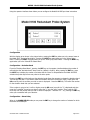
M4560 - Model 9100 Redundant Probe System
Super Systems Inc.
7205 Edington Drive
Cincinnati, OH 45249
513-772-0060, 800-666-4330
Fax: 513-772-9466
www.supersystems.com
SSi’s 9100 Redundant Probe System
USER’S MANUAL
Super Systems Inc. help desk:
1-800-666-4330
SSi Manual 4560 - SERIES 9100-RPS
Page 1 of 9
M4560 - Model 9100 Redundant Probe System
Table of Contents:
Table of Contents:...............................................................................................................................2
Safety: ...............................................................................................................................................3
Wiring Terminals .................................................................................................................................4
eSPP Wiring Terminations ....................................................................................................................4
About the Model 9100 – RPS: ...............................................................................................................5
Electrical Installation:...........................................................................................................................5
Model 9100-RPS Function: ...................................................................................................................5
Configuration ......................................................................................................................................6
Configuration – Deviation Band.............................................................................................................6
Configuration – Alarm Delay .................................................................................................................6
Configuration – Probe (Prb) Select Mode ...............................................................................................7
Configuration – Manual Probe (Prb) Select.............................................................................................7
Typical Electrical Drawing: ...................................................................................................................8
Spare Parts:........................................................................................................................................9
Revision History: .................................................................................................................................9
SSi Manual 4560 - SERIES 9100-RPS
Page 2 of 9
M4560 - Model 9100 Redundant Probe System
Safety:
•
Safety Symbols - Various symbols are used on the instrument, they have the following meaning:
!
Caution (refer to the accompanying documents)
•
Grounding of the temperature sensor shield - In some installations it is common practice to replace the
temperature sensor while the controller is still powered up. Under these conditions, as additional
protection against electric shock, we recommend that the shield of the temperature sensor be
grounded. Do not rely on grounding through the framework of the machine.
•
Installation requirements for EMC - To ensure compliance with the European EMC directive certain
installation precautions are necessary. When using relay or triac outputs it may be necessary to fit a
filter suitable for suppressing the emissions. The filter requirements will depend on the type of load. For
typical applications we recommend Schaffner FN321 or FN612.
•
Routing of wires - To minimize the pick-up of electrical noise, the wiring for low voltage DC and
particularly the sensor input should be routed away from high-current power cables. Where it is
impractical to do this, use shielded cables with the shield grounded at one end.
SSi Manual 4560 - SERIES 9100-RPS
Page 3 of 9
M4560 - Model 9100 Redundant Probe System
Wiring Terminals
eSPP Wiring Terminations
1 – 24 VDC (COM)
2 – 24 VDC ( + )
3 – RS485 RT ( + )
4 – RS485 RT ( - )
5 – SLAVE RS485 ( + )
6 – SLAVE RS485 ( - )
7 – OUTPUT COMMON
8 – OUTPUT 1
9 - OUTPUT 2
10 – OUTPUT 3
11 – OPTIONAL
12 – OPTIONAL
13 - OPTIONAL
14 15 16 17 – PROBE mV INPUT 1 (-)
18 – PROBE mV INPUT 1 (+)
19 - PROBE mV INPUT 2 (-)
20 – PROBE mV INPUT 2 (+)
SSi Manual 4560 - SERIES 9100-RPS
Page 4 of 9
M4560 - Model 9100 Redundant Probe System
About the Model 9100 – RPS:
The Model 9100-RPS is specifically designed to read two SSi Gold Probes, installed in the same furnace.
The Model 9100-RPS controller, a 24 VDC power supply and two 24 VDC relays are mounted and wired on
a piece of DIN rail for easy mounting by the customer. Two other components included with the Model
9100-RPS are the operator interface and the cable connecting the operator interface to the Model 9100RPS.
Electrical Installation:
The Model 9100 – RPS comes mounted on a DIN rail, pre-wired and tested. AC power needs to be
connected to the 24VAC power supply. See the “Typical Electrical Drawing” on the next to last page of this
manual for other required connections.
Model 9100-RPS Function:
The Model 9100-RPS reads a signal from each of the two oxygen probes located in the furnace. Depending
on the 9100-RPS’ configuration, it selects whichever millivolt reading it has been configured to select and
retransmits this millivolt output to your atmosphere controller.
The probe millivolt “deviation band” and the “alarm delay” time are set using the operator interface. When
connected per the electrical drawing, the Model 9100-RPS’s default configuration is set to retransmit the
millivolt signal from the probe with the highest millivolt output. As time passes and if/or when the other
probes millivolt output becomes greater (dependent on the deviation band), the Model 9110 RPS will switch
the output from one probe to the other and send the “new” higher (or lower depending on your
configuration) millivolt signal to the atmosphere controller. The deviation band must be exceeded for the
retransmit to occur.
The “ asterisks (*) “ on the operator interface display indicates which probe’s millivolts are being used by
the furnace atmosphere controller. When the Model 9100-RPS switches the output from one probe to the
other it indicates a “deviation band” alarm condition, flashing an “A” on the operator interface. The “A”
continues to flash until the probe’s output is back within the “deviation band”.
The operator can manually select the probe that he wishes to be used in the carbon calculation. If this
feature is used the 9100 RPS will use the operator selected probe, and NOT switch from one probe to the
other automatically.
The “deviation alarm” is disabled if both probe’s millivolts drop below 950. This should eliminate the
nuisance alarm when the furnace is loaded and the temperature drops.
SSi Manual 4560 - SERIES 9100-RPS
Page 5 of 9
M4560 - Model 9100 Redundant Probe System
Using the operator interface shown below you can configure the Model 9100-RPS per these instructions
Configuration
With the display set as shown in the picture below, pressing the ENT key takes you to the second menu in
the Model 9100 “Deviation Band Menu”. Pressing the NEXT key again takes you to the “Alarm Delay
Menu”. Pressing the NEXT key again takes you to the “Probe (Prb) Select Mode”. Pressing the NEXT key
again takes you to the “Manual Prb Select Menu”.
Configuration – Deviation Band
From the “Deviation Band Menu”, pressing the ENT key on the operator interface displays the number of
millivolts that the “deviation band” alarm is set for (default is 10mV’s). After pressing the ENT key, press
the NEXT key to display the number of minutes that the “alarm” is delayed before the Model 9100 RPS
switches the probe output from one probe to the other probe.
Pressing the ENT key while looking at the deviation band allows the operator to change the deviation band.
The first digit will flash. If you want to make the deviation less than 10 millivolts (mV’s), simply press the
UP arrow key until the number you wish to enter is displayed… Press the ENT key. This enters the number
for the deviation band that you have selected.
If the number is going to be 10 mV’s or higher press the UP arrow key until the “1” is displayed and then
press the “horizontal” arrow key one time to move the “1” into the “tens” position. Then press the “UP”
arrow key until the number that you wish to select is displayed…. Between “10 – 19”, pressing the ENT key
when you are satisfied with your selection.
Configuration – Alarm Delay
When in the ALARM DELAY mode you can press the ENT key to change the number of minutes for which
the alarm can be delayed.
SSi Manual 4560 - SERIES 9100-RPS
Page 6 of 9
M4560 - Model 9100 Redundant Probe System
Configuration – Probe (Prb) Select Mode
To select the probe that you want to use to establish the % Carbon on your carbon controller you can do
one of two things. One, you can install a three-position selector switch as shown on the electrical drawings
(the left-position is Probe 1, the middle position is AUTO, and the right-position is Probe 2), or two, you
press the ENT key. After pressing the ENT key, Press the NEXT key to move to the “PRB Select Mode”. No.
1 represents AUTO mode, and No. 2 represents MANUAL. If the controller is in AUTO you can change to
MANUAL by pressing the UP arrow key until the No. 2 appears in the window with MANUAL beside it. If
the controller is in the MANUAL mode, press the CLR key and the number will change to a “1” and the
word AUTO will appear next to the number 1.
When in the AUTO mode, pressing the ENT key allows you to choose the probe millivolts automatically,
selecting either probe with the “highest mV’s” or the probe with the “lowest mV’s”.
When in the MANUAL mode you press the ENT key to manually select either Probe 1 or Probe 2. On the
operator display the probe millivolts on the first line is Probe 1, and the probe beneath Probe 1 is
designated Probe 2.
Configuration – Manual Probe (Prb) Select
When this mode is selected from the menu options, the probe selected will override the selected probe
based on the automatic settings. If in AUTO mode, the system will continue to select the configured probe
when the deviation band is exceeded. To run continuously in MANUAL mode, you must first select the
MANUAL mode from the Probe Select Mode described above.
SSi Manual 4560 - SERIES 9100-RPS
Page 7 of 9
M4560 - Model 9100 Redundant Probe System
Typical Electrical Drawing:
SSi Manual 4560 - SERIES 9100-RPS
Page 8 of 9
M4560 - Model 9100 Redundant Probe System
Spare Parts:
Description
Power Supply
Gold Probes
Part Number
37135
Check the current part number of your SSi Probe
Revision History:
Rev.
A
B
Description
Initial Release
Manual / Auto Probe Selection Mode
Revised to include new “menu” selections
SSi Manual 4560 - SERIES 9100-RPS
Date
06-09-2005
06/22/2005
08/05/2005
Page 9 of 9