1
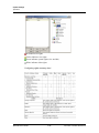
Device Map
Panel Configuration
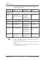
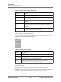
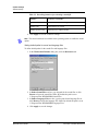
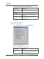
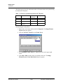
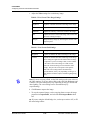
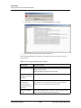
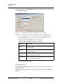
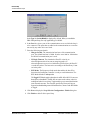
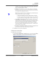
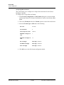
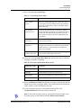
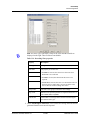
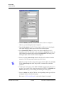
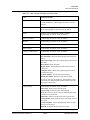
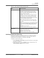
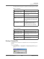
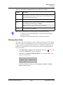
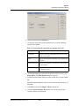
For example, consider the following scenarios:
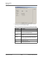
Table 11-1 Explaining Shunt Time and Debounce Time
Scenario
Shunt Time
Debounce Time
Alarm raised at...
1
15 sec
0 sec
16th sec
2
15 sec
10 sec
25th sec
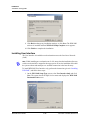
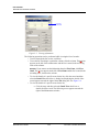
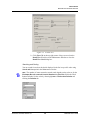
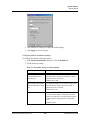
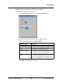
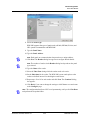
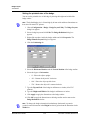
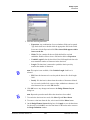
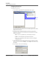
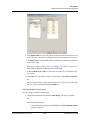
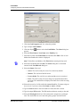
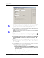
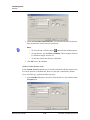
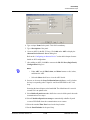
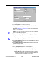
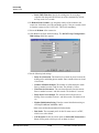
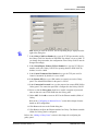
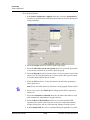
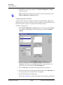
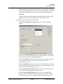
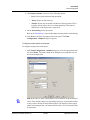
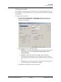
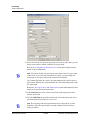
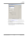
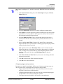
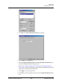
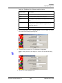
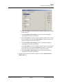
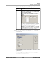
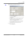
6. Enter the time interval after which the changed state of an input point is
reported.
Example: An input point with a debounce time of 5 can be in active condition for
five seconds before it is reported as an alarm. The same is true when returning to
normal condition. The input point would not report as normal until it was in the
normal state for five seconds.
Note: If the value is set to zero, the debounce time is a minimum of .33 seconds
on events going to normal, but alarms are reported immediately. The debounce
time is 0 seconds on alarm.
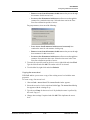
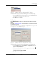
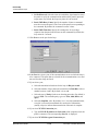
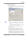
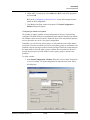
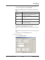
7. Select the Supervised check box to report the troubles when there is a change
in the state of input points.
8. Select Normally Closed or Normally Opened to specify the normal state of
the door.
Note: All
N-1000/PW-2000 alarm input points and N-1000/PW-2000 with an
AEP-5 default to Normally Closed. N-1000/PW-2000-III/IV inputs can be
configured for Normally Open circuits and 3-state supervised circuits.
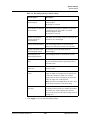
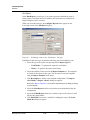
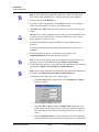
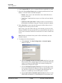
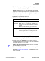
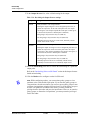
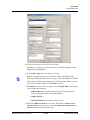
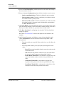
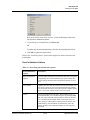
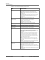
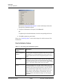
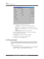
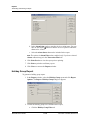
9. Under Report Alarms, select the following:
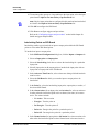
• Never: To prevent from reporting the alarms.
• Always: To report alarms.
• Trouble: To report the trouble conditions. This is typically used for
egress devices to detect tampering. This option is enabled only for
supervised input point.
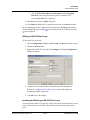
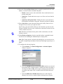
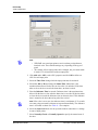
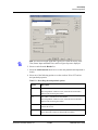
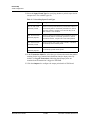
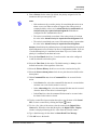
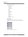
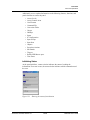
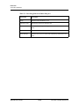
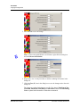
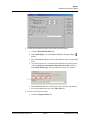
10.Set the Interlocking option for the input point.
Refer to the “Interlocking” section in this chapter for more details on interlocking.
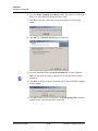
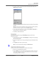
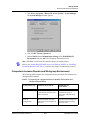
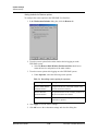
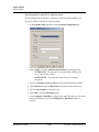
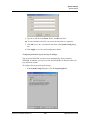
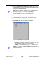
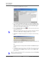
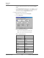
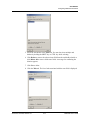
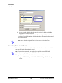
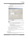
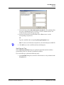
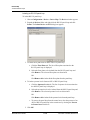
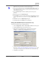
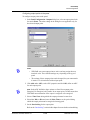
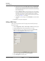
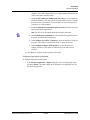
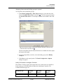
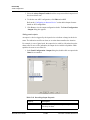
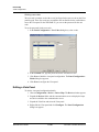
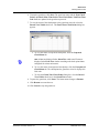
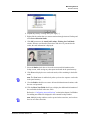
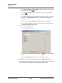
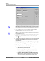
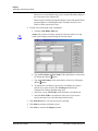
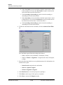
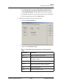
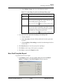
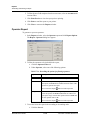
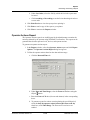
11.Click Next to configure the output points to the panel. The Panel
Configuration - Outputs dialog box appears.
WIN-PAK User’s Guide
11-92
Document 7-001009, Revision 01