1
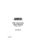
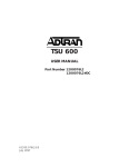
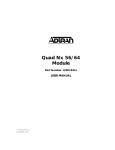
Table of Contents
DBU INTERF ACE OPTION MODULE
(MULTIPORT)
Part Number 1200089L2#HS
USER MANUAL
61200.089L2-1A
November 1995
61200.089L2-1
DBU Interface Option Module User Manual
Table of Contents
901 Explorer Boulevard
P.O. Box 070020
Huntsville, AL 35807
Phone: (205) 971-8000
Fax: (205) 971-8699
© 1995 ADTRAN, Inc.
All rights reserved.
Printed in the USA.
DBU Interface Option Module User Manual
61200.089L2-1
Table of Contents
FEDERAL COMMUNICATIONS COMMISSION
RADIO FREQUENCY INTERFERENCE STATEMENT:
This equipment has been tested and found to comply with the limits for a Class A digital device,
pursuant to Part 15 of the FCC Rules. These limits are designed to provide reasonable protection
against harmful interference when the equipment is operated in a commercial environment. This
equipment generates, uses, and can radiate radio frequency energy and, if not installed and used
in accordance with the instruction manual, may cause harmful interference to radio frequencies.
Operation of this equipment in a residential area is likely to cause harmful interference in which case
the user will be required to correct the interference at his own expense.
Shielded cables must be used with this unit to ensure compliance with Class A FCC limits.
WARNING:
61200.089L2-1
Change or modifications to this unit not expressly approved by the party
responsible for compliance could void the user’s authority to operate the
equipment.
DBU Interface Option Module User Manual
Table of Contents
DBU Interface Option Module User Manual
61200.089L2-1
Table of Contents
Table of Contents
Chapter 1. Introduction ...................................................................................... 1
Dial Backup Overview ........................................................................................... 1
Dial Backup Functional Description .................................................................... 1
Features of the DBU Interface Option Module ................................................... 2
Interfaces ................................................................................................................ 2
Compatibility .......................................................................................................... 3
Dial Backup Option Module Specifications ........................................................ 3
Physical Description .............................................................................................. 4
Chapter 2. Installation ........................................................................................ 5
Unpack & Inspect ................................................................................................. 5
ADTRAN Shipments .............................................................................................. 5
Customer Provides ................................................................................................. 5
Installing the Option Module ............................................................................... 6
Placement of the Option Module .................................................................... 6
Power Connection ............................................................................................ 6
Warranty and Customer Service .......................................................................... 7
Wiring ..................................................................................................................... 8
Configuring External DCE .................................................................................... 8
Originate DCE .................................................................................................. 8
Answer DCE ...................................................................................................... 8
Power-Up Initialization .......................................................................................... 9
Chapter 3. Operation ........................................................................................ 11
Overview ............................................................................................................... 11
Front Panel Indicators/Buttons ...................................................................... 11
Menu Structure ............................................................................................... 11
DBU Menus Are All Submenus ........................................................................... 13
Operation ........................................................................................................ 13
5)PORT Status, Submenu of 1)Status ................................................................ 14
Operation ........................................................................................................ 14
7)PORT CONFIG, Submenu of 2)CONFIG ...................................................... 16
Operation ........................................................................................................ 16
3)FACTORY RESTORE, Submenu of 3)UTIL .................................................... 19
Operation ........................................................................................................ 19
61200.089L2-1
DBU Interface Option Module User Manual
i
Table of Contents
7)PORT UTILITY, Submenu of 3)UTIL ............................................................ 19
Operation ........................................................................................................ 19
2)RUN SELF TEST, Submenu of 4)TEST .......................................................... 20
3)PORT TEST, Submenu of 4)TEST .................................................................. 21
Operation ........................................................................................................ 21
Appendix A. Dial Backup System Messages .................................................. 2 3
List of Figures
Figure 1-1. DBU Option Module ......................................................................... 4
Figure 2-1. Installing the Option Module ........................................................... 6
Figure 3-1. TSU 100 Main Menu Tree ............................................................... 12
Figure 3-2. DBU Option Card Menu Tree ........................................................ 13
Figure 3-3. Port Status Submenu ....................................................................... 14
Figure 3-4. SYNC Status Window ..................................................................... 15
Figure 3-5. Port Configuration Submenu ......................................................... 16
Figure 3-6. Port Utility Submenu ....................................................................... 19
Figure 3-7. Display of Port Name and Firmware Version ................................ 20
Figure 3-8. Port Test Submenu ........................................................................... 21
List of Tables
Table 2-A. V.35 Winchester Pin Connection ...................................................... 8
ii
DBU Interface Option Module User Manual
61200.089L2-1
Chapter 1. Introduction
Chapter 1
Introduction
DIAL BACKUP OVERVIEW
The Dial Backup (DBU) Interface Option Module is one
of the option modules available for use with the
ADTRAN TSU 100/600.
The DBU interface option module installs in the option
slot of the TSU 100/600 and provides a DTE interface
capable of interfacing to various dial backup devices. It
utilizes the full bandwidth of the dial backup network to
backup a single data port in a TSU 100/600. When
backing up multiple data ports, the DBU will rob an 8
kbps channel to maintain data alignment.
The DBU must be installed in slot 2 of the TSU 600.
DIAL BACKUP FUNCTIONAL DESCRIPTION
The DBU interface option module operates in the option
slot of the TSU 100/600 and is under the control of the
TSU 100/600. The DBU is configured from the front
panel or by T-Watch, an external PC program. The
internal menus for its configuration are part of the DBU
card and are automatically installed when the DBU
interface option module is plugged into the TSU 100/
600.
The DBU operates only with TSU 100 code Rev K or
higher and TSU 600 code Rev E or higher.
61200.089L2-1
DBU Interface Option Module User Manual
1
Chapter 1. Introduction
FEATURES OF THE DBU INTERFACE OPTION MODULE
The main features of the DBU Interface Option Module
include the following:
•
Operates using 1 to 24 DS0s
•
Includes an elastic store for absorption of rate
variations
•
Accepts a plug-on port
•
Provides backup multiple TSU 100/600 data ports
•
Provides TSU timing locked to backup network
when backup function is active
•
Operates by menu for easy configuration
•
Offers weekend and time-of-day backup disable
•
Performs an extensive self test
INTERFACES
The DBU Interface Option Module uses the following
interfaces:
2
•
CCITT V.35 electrical (differential)
•
Connector - V.35 Winchester
•
Loopbacks - Local (toward the DCE)
DBU Interface Option Module User Manual
61200.089L2-1
Chapter 1. Introduction
COMPATIBILITY
The DBU Interface Option Module has been tested with
the following external DCE devices:
•
ADTRAN DSU
•
ISU 2x64 (ADTRAN)
•
ISU 128 (ADTRAN)
•
ISU 512 (ADTRAN)
DIAL BACKUP OPTION MODULE SPECIFICATIONS
DTE Interface
CCITT V.35 Synchronous
Rates
56 kbps to 1.536 Mbps in 56 kbps or 64 kbps increments
Clocking
Derived from the external DCE device
Tests
• Local Loopback menu activated
• Interface Test - causes dial out to be activated
• Self Test
Connector
Winchester (V.35), female
61200.089L2-1
DBU Interface Option Module User Manual
3
Chapter 1. Introduction
PHYSICAL DESCRIPTION
The DBU is a module which plugs into the option slot in
the rear of the TSU 100/600; see Figure 1-1.
The rear panel of the option module includes a plastic
plug over a cutout for a plug-on option card. This allows
a plug-on board to be added to the option module,
creating an additional port. The PORT X.1 and X.2
indication is linked to the port numbering philosophy of
the TSU 100/600 product family. The X represents the
slot number, into which the option module is plugged.
For the TSU 100 there is only one option slot. Therefore
the port designation would be 1.1 and, if a plug-on V.35
is present, port 1.2. In a TSU 600 with six option slots,
these port numbers would be port 1.1 to port 6.1. The
numbers appear in the front panel LCD menu displays.
In the TSU 600, the Dial Backup option card must be used
in slot 2.
3
2
2
DIAL BACKUP PORT X.1
PORT X.2/X.3
HOT
REPLACEABLE
1
1 - Cutout for second option card
2 - Screw receptacles for "plug-on" board
3 - Port X.2/X.3 header pins
Figure 1-1
DBU Option Module
4
DBU Interface Option Module User Manual
61200.089L2-1
Chapter 2. Installation
Chapter 2
Installation
UNPACK & INSPECT
Carefully inspect the DBU module for any shipping
damage. If damage is suspected, file a claim immediately
with the carrier and then contact ADTRAN customer
service. If possible, keep the original shipping container
for use in shipping the DBU module back for repair or
for verification of damage during shipment.
ADTRAN Shipments
The ADTRAN shipment includes the following materials:
•
•
DBU Module
DBU User Manual (to be inserted into main TSU
100/600 user manual)
Customer Provides
The customer provides the following:
•
61200.089L2-1
DTE cable
DBU Interface Option Module User Manual
5
Chapter 2. Installation
INSTALLING THE OPTION MODULE
Placement of the Option Module
Figure 2-1 is representative of the action required for
proper placement of the option module. Perform the
following steps to install the option module:
1.
2.
3.
Remove the cover plate from the TSU 100/600 rear
panel.
Slide the option module into the rear panel of the
TSU 100/600 until it is positioned firmly against the
front of the unit.
Fasten the thumbscrews at both edges of the option
module.
For the TSU 600, the DBU module must be in option slot 2.
Cover Plate
TSU 100
Option Module
Figure 2-1
Installing the Option Module
Power Connection
Each option module derives power from the base TSU
100/600 unit. Power to the TSU 100/600 is supplied by
a captive eight-foot power cord.
6
DBU Interface Option Module User Manual
61200.089L2-1
Chapter 2. Installation
WARRANTY AND CUSTOMER SERVICE
ADTRAN will replace or repair this product within five
years from the date of shipment if it does not meet its
published specifications or fails while in service. For
detailed warranty, repair, and return information refer to
the ADTRAN Equipment Warranty, Repair, and Return
Policy Procedure at the end of this manual.
Return Material Authorization (RMA) is required prior to
returning equipment to ADTRAN.
For Service, RMA requests, or more information, contact
one of the numbers listed at the end of this manual.
61200.089L2-1
DBU Interface Option Module User Manual
7
Chapter 2. Installation
WIRING
The DBU option module has a V.35 Winchester-style
connection as defined in Table 2-A.
Table 2-A
V.35 Winchester Pin Connection
PIN
A
B
C
D
E
F
H
J
R
T
V
X
P
S
Y
AA
CCITT
101
102
105
106
107
109
104
104
115
115
103
103
114
114
DESCRIPTION
Protective ground (PG)
Signal ground (SG)
Request to send (RTS) to DCE
Clear to send (CTS) from DCE
Data set ready (DSR) to DTE from DCE
Received line signal detector (DCD) from DCE
Data terminal ready (DTR) to DCE
Ring indicator (RI) from DCE
Received data (RD-A) from DCE
Received data (RD-B) from DCE
RX clock (RC-A) from DCE
RX clock (RC-B) from DCE
Transmitted data (TD-A) to DCE
Transmitted data (TD-B) to DCE
TX clock (TC-A) from DCE
TX clock (TC-B) from DCE
CONFIGURING EXTERNAL DCE
The external DCE is configured as follows:
Originate DCE
1. DTR - Dial number if on
2. CTS - Follows RTS
3. CD - Normal
Answer DCE
1. DTR - Answer if on
2. CTS - Follows RTS
3. CD - Normal
The number to be dialed when DTR is On must be
entered in the originating DCE.
Consult the manual for your external DCE device in
setting the above configuration.
8
DBU Interface Option Module User Manual
61200.089L2-1
Chapter 2. Installation
POWER-UP INITIALIZATION
No initialization input is required. Upon power-up, any
previously configured setting for the DBU is automatically restored.
When the configuration is successfully restored, the LED
labeled OK in the MODULE group on the front panel
turns On. For more information, see the section Front
Panel Operation, in the chapter Operation, of the TSU 100
User Manual. If any alarms are detected during operation, the red LED labeled ALARM in the MODULE
group on the front panel turns On.
61200.089L2-1
DBU Interface Option Module User Manual
9
Chapter 2. Installation
10
DBU Interface Option Module User Manual
61200.089L2-1
Chapter 3. Operation
Chapter 3
Operation
OVERVIEW
The DBU is controlled as part of the TSU 100/600 using
the same methods as described in the TSU 100/600 user
manual.
Front Panel Indicators/Buttons
Refer to the description of the TSU 100/600 front panel
indicators and buttons in the TSU 100/600 user manual.
Menu Structure
The DBU menus appear as a subset of, and operate the
same as, menus for the TSU 100/600. The menus are
accessed by selecting 1 DIALBU under the PORT menu
items.
Figure 3-1 shows the TSU 100/600 Main menu with the
PORT menu items in bold italics.
Figure A-1 in appendix TSU 100 Menu Tree in the TSU
100 User Manual is a complete menu tree diagram.
61200.089L2-1
DBU Interface Option Module User Manual
11
Chapter 3. Operation
% AS
1) NI PERF RPTS
2) NI ERRORS
1) STATUS
%EF
ES
SES
UAS
(ALARM LIST)
3) ACTIVE ALARMS
END OF LIST
4) VIEW HISTORY
(HISTORY LIST)
END OF HISTORY
DTE DATA/
5) PORT STATUS
6) REMOTE PORT
0.1 Nx56/64
DTE STATUS
(OPTION PORTS)
PORT RATE
1) FORMAT
1) NETWORK (NI)
2) UNIT
2) CODE
1) CNTRL PORT
3) YEL ALARM
2) DIAL OUT
4) XMIT PRM
5) TIMING MODE
2) CONFIG
3) MAP XCHANG
6) SET LBO
OFF
AUTO
7) INBAND LPBCK
1) MAP A @ HH:MM
8) BIT STUFFING
2) MAP B @ HH:MM
4) MAP IN USE: A (B)
1) COPY A > TEMP
2) CREATE TEMP
3) REVIEW MAP A
5) DS0 MAP A
MAIN MENU
4) REVIEW TEMP
5) EDIT TEMP
6) APPLY TEMP > A
1) COPY B > TEMP
2) CREATE TEMP
1) INTFACE
3) REVIEW MAP B
2) RATE (56/64)
4) REVIEW TEMP
6) DS0 MAP B
3) TX CLK CNTRL
5) EDIT TEMP
4) DATA
6) APPLY TEMP > B
5) CTS
7) PORT CONFIG
0.1 Nx56/64
6) DCD
(OPTION PORTS)
7) DSR
8) “0” INHIB
TIME: HH:MM:SS
1) TIME/DATE
DATE: MM/DD/YY
2) FACTORY RESTORE
3) UTIL
(Returns all configurations
to factory settings)
3) NEW PASSCODE
SET PASSCODE
VERIFY PASSCODE
Set Unit ID
4) UNIT ID
(Displays Current
Software Revision)
5) SOFTWARE REV
6) PORT UTILITY
0.1Nx56/64
(OPTION PORTS)
1) LOCAL LOOPBK
2) REMOTE LOOPBK
1) NETWORK TESTS
3) PATTERN
4) TEST
LINE ON
PAYLOAD ON
ATT INBAND LLB
NO LOOPBACK
ANSI FDL LLB
ANSI FDL PLB
QRSS ALL DS0s
NO LOOPBACK
QRSS TST DS0s
NONE
4) PATTERN RESULT
(Displays Results)
(Displays Results)
2) RUN SELF TEST
3) PORT TEST
0.1Nx 56/64
(OPTION PORTS)
1) LOOPBK
2) 511 PATT
3) DISP 511 RESLT
(Displays Results)
4) CANCEL TESTS
Figure 3-1
TSU 100 Main Menu Tree
12
DBU Interface Option Module User Manual
61200.089L2-1
Chapter 3. Operation
DBU MENUS ARE ALL SUBMENUS
The DBU menus are accessed from, and operated the
same as, menus for the TSU 100. As shown in the menu
items in bold italics in Figure 3-1, the DBU items are
submenu choices of the four Main menus.
Each of the DBU submenu items is shown in Figure 3-2
and discussed in the following paragraphs. All are
accessed by the same method.
1)DCE Data/CK (RXD TXD DCD LCK)
2)DCE Status (RTS CTS DTR DSR)
3)Backup Rate
5)Port Status
4)Sync Status
5)Backup Status
1)Backup: Enable/Disable
7)Port Config
2)Backup Delay:(1sec/3 sec/10 sec/30 sec/1 min/5 min/10 min)
3)Restore Delay: (1 sec/3 sec/10 sec/30 sec/1 min/5 min/10 min/Never)
MAIN MENU
4)DBU Mode: Originate-Answer/Originate-ANS.ANY
5)DS0 Rate: 56K/64K
6)Number DS0: (1-24)
7)Weekend BCKUP: Enable/Disable
8)Enable HR: 0-24
9)Disable HR: 0-24
10)DCE RATE ALRM: Enable/Disable
Dial Backup
6)Port Util
Firmware Rev
3)Port Test
1)Loopback: Local/Off
2)Force BCKUP: Off/On
3)Interface TST: Off/On
4)DCE Data/CK (RXD TXD DCD LCK)
5)Check DCE Rate
Figure 3-2
DBU Option Card Menu Tree
Operation
With the cursor on one of the four Main menu choices,
press the Enter or the number key. The results are a
display of the first two submenu items with the cursor
on the first item. Use the Scroll Down key to place the
cursor on the desired item then press Enter. This
displays the first two submenu choices.
61200.089L2-1
DBU Interface Option Module User Manual
13
Chapter 3. Operation
5)PORT STATUS, SUBMENU OF 1)STATUS
The Status menu branch provides the ability to view the
status of the TSU 100 operation. It displays the status of
the monitored signal line on the DBU option board and
the backup rate for which the DBU card is configured.
Operation
To display Figure 3-3 on the TSU 100, start with the
cursor on Main menu item 1)STATUS and do the
following:
1.
2.
3.
Press the Enter or the number 1 key. This displays
the first two Status submenu items with the cursor
on 1)NI PERF RPTS.
Use the Scroll Down key to place the cursor on
5) PORT STATUS and press the Enter key. This
displays the first available port.
Use the scroll keys to identify 1.1 DIALBU and press
the Enter key.
Figure 3-3
Port Status Submenu
The DBU interface offers the status screens listed in this
manual. For other option modules, refer to the appropriate separate manual.
DBU Status
Select 1.1 DIALBU
1) DCE DATA/CK
2) DCE STATUS
3) BACKUP RATE
4) SYNC Status
5) Backup Status
14
DBU Interface Option Module User Manual
61200.089L2-1
Chapter 3. Operation
DCE DATA/CK: Shows the status (active or not active)
of the following lines:
TXD
RXD
DCD
LCK
Transmit data to the DCE
Receive data from the DCE
Data carrier detect from DCE
Lock status of the phase locked loop
DCE Status: Shows the status (active or not active) of
the following lines:
RTS
CTS
DTR
DSR
Request to send to DCE
Clear to send from DCE
Data terminal ready to DCE
Data set ready from DCE
Backup Rate: Displays the data rate to which the DBU
port is configured to Backup.
SYNC Status: Displays an indication of sync between
the near end TSU and the far end TSU. An asterisk
indicates when each end is in sync (see Figure 3-4).
Figure 3-4
SYNC Status Window
Backup Status: Indicates the current state of Backup:
Backup - IDLE
No backup attempt in progress
Backup - ATTEMPT Backup started, but no Carrier
Detect from external DCE
Backup - ACTIVE
Backup Mode and external DCE
has carrier detect.
Exit the displays as described in the TSU 100 User
Manual.
61200.089L2-1
DBU Interface Option Module User Manual
15
Chapter 3. Operation
7)PORT CONFIG, SUBMENU OF 2)CONFIG
The 7)PORT CONFIG submenu is used for configuration of the DIALBU option module.
Operation
To display Figure 3-5 on the TSU 100, starting with the
cursor on Main menu item 2)CONFIG, do the following:
1.
2.
3.
Press the Enter or the number 2 key. This displays
the first two Configuration submenu items with the
cursor on 1)NETWORK (NI).
Use the Scroll Down key to place the cursor on
7)PORT CONFIG and press the Enter key.
Use the scroll keys to identify 1.1 DIALBU. Only
the bottom line of the display changes.
Figure 3-5
Port Configuration Submenu
To select Port Configuration, press the Enter key. This
displays the first of 10 submenu items. They are:
16
1.
BACKUP: (ENABLE/DISABLE) - This selects the
global Enable and Disable for the DBU option card.
2.
BACKUP DELAY: (1 sec, 3 sec, 10 sec, 30 sec,
1 min, 5 min, 10 min) - This selects the time allowed
to elapse between the network going into alarm and
the backup beginning.
3.
RESTORE DELAY: (1 sec, 3 sec, 10 sec, 30 sec,
1 min, 5 min, 10 min, never) - This selects the time
that elapses between the network going out of alarm
and the backup call being taken down. If never is
selected, the user must deactivate the backup mode.
DBU Interface Option Module User Manual
61200.089L2-1
Chapter 3. Operation
4.
The DBU can activate backup in two basic modes:
Single End Failure or Both End Failure:
Single End Failure (Mode: ORIG/ANS.ANY) - In
this mode, a network failure detected at either end
of the circuit causes a backup to be activated. The
DBU at the failed end initiates a call to the opposite
end which goes into backup mode upon receiving a
call. This is particularly useful for Fractional T1
applications where a failure at one end cannot be
reported to the other end.
In this mode, the unit will go into backup mode on any
received call, even a wrong number.
Both End Failure (Mode: ORIGINATE or ANSWER) - In this mode, both ends of the circuit must
detect a network failure before backup is activated.
One DBU is set to Originate and the other to
Answer. Upon a network failure, only the Originate
DBU initiates backup by dialing the Answer end.
Once called, the Answer DBU goes into backup
mode only if a network failure is detected. This is
ideal for full T1 point-to-point applications where a
failure at one end is reported to the other end
(Yellow alarm). This eliminates the possibility of a
wrong number initiating a backup.
Only the DBU set to ORIGINATE activates a backup for
network failure. The ANSWER DBU must also detect
network failure to go into backup mode.
5.
61200.089L2-1
DS0 RATE: (56K/64K) - This selects the rate for the
DS0 to be used on the backup network. If 64K/DS0
is desired for an ISDN backup, confirm that the dial
up ISDN network is provisioned for 64K clear
channel access.
DBU Interface Option Module User Manual
17
Chapter 3. Operation
6.
NUMBER DS0: (1-24) - The number of DS0s that
are backed up is entered by using the numeric
keypad on the front of the TSU 100/600. Verify that
the two above settings do not exceed available
bandwidth. This can be done from Port Status ->
Backup Rate. Verify displayed backup rate matches
the available bandwidth on the dialup network.
7.
WEEKEND BACKUP: (ENABLE/DISABLE) - If no
backup is desired from midnight Friday to midnight
Sunday, set this selection to DISABLE, otherwise to
ENABLE.
8.
ENABLE HR: (1-24) - The hour that the backup will
be enabled can be entered from the numeric keyboard.
9. DISABLE HR: (1-24) - The hour that the backup will
be disabled can be entered from the numeric
keypad.
0. DCE RATE ALARM: (ENABLE/DISABLE) - When
this alarm is enabled, the DBU will monitor the
clock being received from the external DCE while
not in backup. When the alarm is disabled, the
clock will only be checked when CTS goes high
during backup.
For items 7, 8, and 9 to function properly, verify that the
time and date in the TSU 100/600 are set correctly. Consult
the TSU 100/600 user manual for instructions on setting
date and time.
Map B of the TSU 100/600 is used as the backup map. The
data ports to be backed up should be mapped in DS0 1 and
in contiguous DS0s until the full bandwidth of the Dialup
Network is allocated.
For configuration of an external DCE see the section
Configuring the External DCE in the chapter Installation.
18
DBU Interface Option Module User Manual
61200.089L2-1
Chapter 3. Operation
3)FACTORY RESTORE, SUBMENU OF 3)UTIL
This selection is used to restore the factory default
settings for all Dial Backup option module parameters.
Operation
To return the unit to the opening Main menu with all the
factory default settings restored, do the following:
1.
2.
Follow the standard operating procedure to access
the 3)UTIL menu items.
With the cursor on 3)FACT RESTORE, press
the Enter key.
7)PORT UTILITY, SUBMENU OF 3)UTIL
The 7)PORT UTILITY submenu is used primarily to
access the display of the current software information
for each port installed in the unit. This information is
required when requesting assistance from ADTRAN
Technical Support or when updates are needed.
Operation
To display Figure 3-6 on the TSU 100, do the following:
1.
2.
Follow the standard operating procedure to access
the 3)UTIL menu items.
With the cursor on 7)PORT UTILITY, press the
Enter key. This displays the first available port.
Figure 3-6
Port Utility Submenu
61200.089L2-1
DBU Interface Option Module User Manual
19
Chapter 3. Operation
To display the port name and the firmware version
installed as shown in Figure 3-7, do the following:
1.
2.
Use the Scroll keys to move through the available
ports, or enter the port number with the number
key.
When the desired port name is displayed, press the
Enter key.
Figure 3-7
Display of Port Name and Firmware Version
Press the Cancel key to exit or to select another port.
2)RUN SELF TEST, SUBMENU OF 4)TEST
This menu item is used to execute both the internal test
of the TSU 100/600 and the DBU. The results of the
Self Test are shown on the TSU 100 display. For additional information on Self Test, see the chapter Operation
of the TSU 100/600 user manuals.
To activate a Self Test, do the following:
1.
2.
20
Follow the standard operating procedure to access
the 4)TEST menu items.
With the cursor on 2)RUN SELFTEST, press the
Enter key. This results in a changing TSU 100
display, showing the test outcome.
DBU Interface Option Module User Manual
61200.089L2-1
Chapter 3. Operation
3)PORT TEST, SUBMENU OF 4)TEST
This menu item is used to activate testing of specific
data ports. It also controls the activation of loopbacks
and the initiation of data test patterns. Test results are
shown on the TSU 100 display.
The execution of port tests disrupts normal data flow in the
port being tested.
Operation
To display Figure 3-8 on the TSU 100, start with the
cursor on 3)PORT TEST and press the Enter or number
3 key. This displays the available ports.
Figure 3-8
Port Test Submenu
DIALBU: The Nx interface offers the following test
functions:
1) LOOPBK: (OFF/LOCAL) Initiates a loopback
towards the DCE.
2) FORCE BCKUP: (OFF/ON) - This section is used to
force a backup to occur even if the NI is not in
alarm.
3) INTERFACE TST: (OFF/ON) - This test causes the
DCE to dial its stored number. This is useful to
determine if the external DCE is correctly
configured.
61200.089L2-1
DBU Interface Option Module User Manual
21
Chapter 3. Operation
4) DCE DATA/CK - Allows status of DCD and LCK to
be monitored while the INTERFACE TST is on. If
the dial up network is correctly configured, there
should be an asterisk over DCD and LCK.
5) CHECK DCE RATE - Measures the clock rate
provided by the external DCE to the Dial Backup
option card. If this test is performed during an
active backup, data will temporarily be disrupted.
22
DBU Interface Option Module User Manual
61200.089L2-1
Appendix A. Dial Backup System Messages
Appendix A
Dial Backup System Messages
The Dial Backup system messages are the following:
61200.089L2-1
•
RATE MISMATCH - The dial backup configured rate
does not match the rate provided by the DCE.
•
PLL Alarm - The Phase Locked Loop (PLL) is
unable to lock on the clock provided by the DCE
interface.
•
Zeros Alarm - All 0s data being sent to the DCE
interface.
•
Data Path Alarm - Error in propagation of data
through the FIFOS.
•
DCE Rate Alarm - The clock provided by the
external DCE does not match the current
configuration.
DBU Interface Option Module User Manual
23
Appendix A. Dial Backup System Messages
24
DBU Interface Option Module User Manual
61200.089L2-1
Product Support Information
Presales Inquiries and Applications Support
Please contact your local distributor, ADTRAN Applications Engineering, or ADTRAN Sales:
Applications Engineering (800) 615-1176
Sales
(800) 827-0807
Post-Sale Support
Please contact your local distributor first. If your local distributor
cannot help, please contact ADTRAN Technical Support and have
the unit serial number available.
Technical Support
(800) 726-8663
Repair and Return
If ADTRAN Technical Support determines that a repair is needed,
Technical Support will coordinate with the Return Material Authorization (RMA) department to issue an RMA number. For information regarding equipment currently in house or possible fees
associated with repair, contact RMA directly at the following
number:
RMA Department
(205) 971-8722
Identify the RMA number clearly on the package (below address),
and return to the following address:
ADTRAN, Inc.
RMA Department
901 Explorer Boulevard
P. O. Box 070020
Huntsville, Alabama 35807
RMA # _____________
November 1996
QUICK START GUIDE
DBU
(MUL TIPORT)
QUICK ST ART GUIDE
Follow the steps provided in this guide to install and test
the DBU.
Install the DBU module in slot 2 of the TSU 600 or slot 1
of the TSU 100/120.
Upon a network failure, only the Originate DBU initiates
backup by dialing the Answer end. Once called, the
Answer DBU goes into backup mode only if a network
failure is detected. This is ideal for full T1 point-to-point
applications where a failure at one end is reported to the
other end (Yellow alarm). This eliminates the possibility
of a wrong number initiating a backup.
2. VERIFY SOFTWARE REVISION
5. CONFIGURE DBU AND DCE
Verify the TSU 100/600 code revision:
Single End Failure Configuration
1. INSTALL DBU
• TSU 600 code must be Rev. G or higher.
• TSU 100 code must be Rev. P or higher.
• TSU 120 code must be Rev. E or higher.
If Code revision is incorrect, contact ADTRAN Customer
Service at (800) 726-8663.
3. CONFIGURE THE TSU 100/600/120
Configure the TSU 100/600/120 for operation.
4. DETERMINE DESIRED OPERATING MODE
The DBU can activate backup in two basic modes:
Single End Failure or Both End Failure.
Single End Failure (Mode: ORIG/ANS ANY)
In this mode, a network failure detected at either end of
the circuit causes a backup to be activated. The DBU at
the failed end initiates a call to the opposite end which
goes into backup mode upon receiving a call. This is
particularly useful for Fractional T1applications where a
failure at one end cannot be reported to the other end.
In this mode, the unit will go into backup mode
on any received call, even a wrong number.
DCE (Both Ends)
DTR - Dial if on
DCD - Normal
DSR - Off Idle + Test
CTS - Follow RTS
DBU (Both Ends)
BACKUP: ENABLE
DBU MODE: ORG/ANS ANY
Set number of DS0s to backup
(1-24)
Set rate per DS0 (56K or 64K)
Both End Failure Configuration
Set the external DCE V.35 interface to the following
modes:
Originate Unit
DTR - Dial if on
DCD - Normal
DSR - OFF idle + test
CTS - Follow RTS
Answer Unit
DTR - Answer if on
DCD - Normal
DSR - OFF idle + test
CTS - Follow RTS
Set the DBU configuration
CONFIGURE => PORT CONFIG => X.1 DIALBU:
Originate Unit
BACKUP: ENABLE
DBU MODE: ORIGINATE
Set number of DS0s to
backup (1-24)
Set rate per DS0
(56K or 64K)
Answer Unit
BACKUP: ENABLE
DBU MODE: ANSWER
Set number of DS0s to
backup (1-24)
Set rate per DS0
(56K or 64K)
6. VERIFY BACKUP DATA RATE
Both End Failure
(Mode ORIGINATE or ANSWER)
In this mode, both ends of the circuit must detect a
network failure before backup is activated. One DBU is
set to Originate and the other to Answer.
61200.089L2-13B
DBU (Multi Port) Quick Start Guide
1
Verify that the rate the DBU is configured for matches
that of the external DCE for both the answer and the
originate unit.
Both End Failure Mode
To test the backup, perform the following steps:
a.
• The DBU configured rate is found under
STATUS => PORT STATUS => 3)BACKUP RATE. b.
• The clock provided by the external DCE is measured
by TEST => PORT TEST =>
5)CHECK DCE RATE. c.
d.
If these two numbers do not match, check the
e.
configuration of the DBU and the external DCE.
f.
7. CONFIGURE BACKUP MAP
Follow steps (a) and (b), above, from the
ORIGINATE or ANSWER unit.
Disconnect the T1 interface cable, causing a network
failure at both ends.
Follow step (d), above.
Reconnect the T1 interface cable. Verify that the
CSU LEDs show OK.
Follow step (f), above.
Follow step (g), above.
9. PRODUCT SUPPORT INFORMATION
Configure Map B of the TSU 100/600/120. The ports to
be backed up are mapped in DS0 1, continuing for the
number of DS0s to equal the bandwidth of the backup
DCE.
Presales Inquiries and Applications Support
Please contact your local distributor, ADTRAN
Applications Engineering, or ADTRAN Sales:
8. TEST OPERATION
Applications Engineering
Sales
This test is used to verify the integrity of the backup line
prior to use.
Single End Failure Mode
To test the backup, perform the following steps:
a.
b.
c.
(800) 615-1176
(800) 827-0807
Post-Sale Support
Please contact your local distributor first. If your local
distributor cannot help, please contact ADTRAN
Technical Support and have the unit serial number
available.
Loop up the Nx56/64 at the far end unit by sending
Technical Support
(800) 726-8663
remote V.54 loopback from the Nx56/64 being
backed up in the local end unit. (V.54 loopback
Repair and Return
cannot be sent over the backup link.)
If ADTRAN Technical Support determines that a repair
Turn on 511 pattern generation in the Nx56/64 in
is needed, Technical Support will coordinate with the
the local end unit and verify sync.
Return Material Authorization (RMA) department to
In the local unit DBU, set
TEST => PORT TEST => 2)FORCE BCKUP to ON. issue an RMA number. For information regarding
equipment currently in house or possible fees associThis causes a dial backup connection to be
ated with repair, contact RMA directly at the following
established.
number:
Data on the T1 circuit is disrupted for
the duration of this test.
RMA Department
(205) 971-8722
Identify the RMA number clearly on the package
Verify that after the backup is established, the
(below address), and return to the following address:
Nx56/64 in the local unit again has 511 pattern
sync.
ADTRAN, Inc.
e. In the local unit DBU, set
TEST => PORT TEST => 2)FORCE BCKUP to OFF.RMA Department
901 Explorer Boulevard
This causes the dial backup connection to be
P.O. Box 070020
disconnected.
Huntsville, Alabama 35807
f. Turn off 511 pattern generation in the Nx56/64 in the
local unit.
g. Loop down the Nx56/64 in the far end unit by turning
RMA # _____________
off V.54 Loopback from the Nx56/64 in the local
unit.
d.
2
DBU (Multi Port) Quick Start Guide
61200.089L2-13B
NOTICE
The Dial Backup Option Module (p/n 1200.089L2) operates only in TSU's
meeting the following requirements.
TSU Type
TSU 100
TSU 120
TSU 600
TSU 600L2
HSU 100
HSU 600
TSU Type
TSU 100
Minimum Software Revision for Multiport Backup
P
E
G
A
Not Supported
Not Supported
Hardware Requirements
If multiple data ports are being backed up, DS0 number 1
must be mapped to a second generation Nx56/64(p/n
1202.054L1) in the backup map.
TSU 120
No Special Requirements
TSU 600
Same as the TSU 100, and the DBU must be installed in
slot 2.
TSU 600L2
Same as the TSU 100, and the DBU must be installed in
slot 2.
For further assistance, please contact ADTRANTechnical Support at 1-800726-8663.
61200.089L2-17A