1
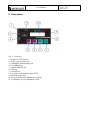
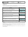
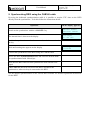
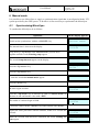
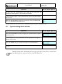
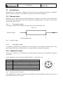
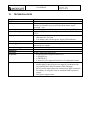
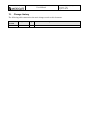
MICROSYNC User Manual Microgate s.r.l. Via Stradivari, 4 Stradivaristr. 39100 BOLZANO - BOZEN ITALY MicroSync User Manual Doc: MSY_I_100_001_EN Versione: 1.00 Pagina 2 di 20 Contents 1. INTRODUCTION ......................................................................................................... 3 2. DESCRIPTION ............................................................................................................ 4 3. SWITCHING ON/OFF ................................................................................................. 5 4. BASIC USE ................................................................................................................. 6 5. SYNCHRONIZING REI2 USING THE CAB146 CABLE ............................................. 7 6. MANUAL MODE ......................................................................................................... 8 6.1. Synchronizing MicroSync ................................................................................................... 8 6.2. Synchronizing other devices................................................................................................ 9 7. BATTERY RECHARGE ............................................................................................ 10 8. SATELLITE SIGNAL ................................................................................................ 11 9. CONFIGURATION PARAMETERS .......................................................................... 12 10. CONNECTIONS ........................................................................................................ 15 10.1. Banana jacks ...................................................................................................................... 15 10.1.1. The signal in output .................................................................................................... 15 10.1.2. The signal in input ...................................................................................................... 15 10.2. Amphenol socket ............................................................................................................... 15 11. MAINTENANCE, AMBIENT CONDITIONS AND WARNINGS REGARDING USE . 17 11.1. Cleaning ............................................................................................................................. 17 11.2. Ambient conditions ........................................................................................................... 17 11.3. Attention ............................................................................................................................ 17 12. TECHNICAL DATA ................................................................................................... 18 13. CHANGE HISTORY .................................................................................................. 19 Figures. Fig. 1 – Overview................................................................................................................................. 4 Fig. 2 – signal in output. .................................................................................................................... 15 Fig. 3 –Amphenol socket connector .................................................................................................. 15 MicroSync User Manual Doc: MSY_I_100_001_EN Versione: 1.00 Pagina 3 di 20 1. Introduction MicroSYNC is the state-of-the-art in synchronizers. Inside its compact container is a GPS receiver able to guarantee synchronization accuracy of ±1µs in relation to UTC time and a 1 ppm heatcompensated internal time base able to ensure the possibility of synchronization even when there is no satellite signal. As well as showing the time currently set in the synchronizer, the display with 2 16-character lines makes it possible to view the time of its next synchronization signal and to view its status, and allows easy configuration of work parameters. Thanks to backlighting it can also be used when visibility is poor. Simplicity of use was one of Microgate’s aims in the device’s design. The operations required are switching it on, waiting for the appearance of the signal indicating GPS synchronization and connecting the cables to synchronize the external device. In combination with the REI2 stopwatch, it provides a system with an accuracy that had hitherto been inconceivable, keeping the internal time base synchronized with the UTC signal. In this manual the keys to press are shown between angled brackets, for example, press <ENT> means press the key with ENT on it, while the options suggested by MicroSYNC are shown in bold. In the display illustrations, a time written in italics means that that time is running on the synchronizer. An underlined figure indicates that the blinking cursor is in that position and the MicroSync is waiting for an input. This manual is for firmware version 00001. MicroSync User Manual 2. Description Fig. 1 – Overview 1. Position of GPS antenna 2. SYNC: green banana jack 3. COMMON: black banana jack 4. UP ARROW key 5. DOWN ARROW key 6. ENT key 7. ON/OFF key 8. Low battery and recharge status LED 9. Recharge jack socket 10. 2 line x 16 character alphanumeric display 11. I/O SERIAL: 6-pole Amphenol socket Doc: MSY_I_100_001_EN Versione: 1.00 Pagina 4 di 20 MicroSync User Manual Doc: MSY_I_100_001_EN Versione: 1.00 Pagina 5 di 20 3. Switching on/off To switch on the synchronizer, press the <ON/OFF> key for about a second. The display lights up and the serial number and the firmware version installed appear on the display. Serial: xxxxx Version: xxxxx When switched on, MicroSync shows the time 00:00:00 and waits to receive a signal from the GPS satellites or external synchronization. MicroSync 00:00:00 To switch off the MicroSync keep the <ON/OFF> key pressed down until the words Good bye appear on the display. As soon as the <ON/OFF> key is released, the synchronizer switches off. Good bye. The device switches off automatically when the battery charge level reaches the minimum level, briefly showing the words Battery low – Good bye. Battery low Good bye. To activate lighting up of the display, briefly press any key. The display stays lit up for about 1 minute. MicroSync User Manual Doc: MSY_I_100_001_EN Versione: 1.00 Pagina 6 di 20 4. Basic use To synchronize your stopwatch, whether it is a Microgate REI2 or a RaceTime2, or to synchronize the devices of other producers, follow the instructions given below: Operation On the display appears: Switch on the synchronizer with the <ON/OFF> key Serial: xxxxx Version: xxxxx The internal time is shown on the display MicroSync 00:00:00 Position the synchronizer so that there are no obstacles between it and the sky Wait until running time appears on the display MicroSync 10:12:05 Connect the device to be synchronized to the synchronizer using banana jack sockets (see Fig. 1 – Overview on p. 4) Press the <ENT> key to view the next synchronization time MicroSync 10:13:00 Set the synchronization time on the device and wait for the impulse to be sent The time of the next synchronization depends on the parameter selected in the synchronization parameters. The time indicated by the synchronizer may differ from the real time until the correct time zone is set. This in no way affects the accuracy of the seconds shown on the display or the generation of the signal at ±1 µs in relation to UTC time. For operational details consult the operational notes for the various devices provided by the respective producers. MicroSync User Manual Doc: MSY_I_100_001_EN Versione: 1.00 Pagina 7 di 20 5. Synchronizing REI2 using the CAB146 cable By using the dedicated synchronization cable it is possible to acquire UTC time on the REI2 directly from the synchronizer. To do this follow the instructions below: Operation On the display appears: Switch on the synchronizer with the <ON/OFF> key Serial: xxxxx Version: xxxxx The internal time is shown on the display MicroSync 00 :00 :00 Position the synchronizer so that there are no obstacles between it and the sky Wait until running time appears on the display MicroSync 10:12:05 Connect the synchronizer to the REI2 using the CAB146 cable Access the REI2 Synchronization menu and select the desired mode for synchronization with MicroSync Wait until the REI2 internal clock synchronizes itself with the GPS signal If Base GPS has not been selected on the REI2, disconnect the synchronizer, otherwise keep it connected to the REI2. See the chapter Synchronization of the various REI2 manuals for detailed operational instructions for the REI2. MicroSync User Manual Doc: MSY_I_100_001_EN Versione: 1.00 Pagina 8 di 20 6. Manual mode It is possible to use MicroSync to supply a synchronization signal that is not aligned with the UTC system provided by the GPS system. To do this it is first necessary to synchronize the MicroSync. 6.1. Synchronizing MicroSync To synchronize MicroSync do as follows: Operation On the display appears: Switch on the synchronizer with the <ON/OFF> key Serial: xxxxx Version: xxxxx The internal time is shown on the display MicroSync 00:00:00 Keep the keys <Up arrow> and <Down arrow> pressed down together until the words Entering setup appear The words Setup timezone appear on the display press the <Up arrow> key … Entering setup Setup time zone Setup sync period press the <Up arrow> key … …until the words Set manual mode appear Set manual mode press the <ENT> key the time begins to blink Set sync time 00:00:00 Press the <Up arrow> key to increase its value or <Down arrow> to decrease it and confirm the value with <ENT> The tenths of a minute begin to blink Set sync time 10:00:00 Correct the value with the <Arrow> keys and confirm with <ENT> Repeat the same procedure with the minutes, tenths of a second and seconds Set sync time 10:10:00 When the seconds value has been confirmed, the words Waiting for sync appear Waiting for sync MicroSync User Manual Doc: MSY_I_100_001_EN Versione: 1.00 Pagina 9 di 20 Operation On the display appears: In this way the synchronizer sets itself up to wait for the synchronization impulse on the banana jack sockets Connect the MicroSync to the synchronizing device using the banana jack sockets When the synchronization impulse is received, a beep is emitted and the words External sync done appear External sync done At any moment the procedure can be abandoned by pressing the <ON/OFF> key. 6.2. Synchronizing other devices Operation Now your synchronizer is ready to supply the synchronization signal to other devices On the display appears: MicroSync 10:12:05 Connect the device to be synchronized to the synchronizer using the banana jack sockets Press the <ENT> key to view the next time for synchronization MicroSync 10:13:00 Set the synchronization time on the device and wait for the impulse to be sent During manual mode functioning the precision provided is that of the internal time base and not the far more precise one of the GPS time base. MicroSync User Manual Doc: MSY_I_100_001_EN Versione: 1.00 Pagina 10 di 20 7. Recharging the batteries To recharge the batteries you need only plug a power supply voltage of 9 to 20V into the appropriate jack socket (see Fig. 1). Recharge starting with completely flat batteries lasts about 3 hours. We advise you to keep MicroSync switched off while charging, using the dedicated Microgate adaptors. “Low battery” is signal LED on the display by the blinking battery symbol and the blinking red LED. The device can also function if powered externally, once again using the recharge jack socket with voltages of 9 to 20V. In this case the built-in battery is constantly recharged in order to keep it at least 90% charged. The battery symbol that fills up at the bottom right of the display shows recharging is in progress. At any moment it is possible to find out the recharge status of the batteries by pressing and immediately releasing the <ON/OFF> key. On the display the status of the remaining charge is shown as a percentage. Battery: xx% Satellites: x The LED indicates the status of the batteries and of the recharge voltage: Red: battery almost flat, remaining autonomy less than 20% Orange: presence of external power supply and recharge in progress Green: battery recharge completed The built-in batteries do not suffer from memory effect so it is possible to recharge the device at any moment. The Li-ion batteries used by MicroSync have a longer working life if they are frequently charged. MicroSync User Manual Doc: MSY_I_100_001_EN Versione: 1.00 Pagina 11 di 20 8. Satellite signal Reception of the satellite signal is necessary to guarantee a precision of ±1 µs in relation to the UTC signal and for synchronization of the internal time base. Confirmation of correct satellite signal reception is indicated by the antenna symbol at the bottom right of the display. The synchronizer waits to receive the signal from at least 4 satellites before linking its time base to the UTC time base. When the internal time base has been aligned to that of the clocks of the GPS satellites, it is kept aligned by means of the PPS signal received once a second. The maximum deviation between the synchronizer and the UTC time base is ±1 µs (1/1.000.000 s). The stability of the time base aligned with the GPS system is not affected either by climatic conditions or by ageing of the device. If the satellite signal is lost, the antenna signal begins to blink. If the signal does not return in sufficient time to guarantee the maintenance of maximum precision, the antenna symbol disappears. At any moment it is possible to find out the number of satellites received by briefly pressing the <ON/OFF> key. The word Satellites: precedes the number of satellites currently being received. Battery: xx% Satellites: x The satellite signal is not received inside tunnels and other underground environments. Reception is difficult inside buildings. In the latter case, the synchronizer should be placed near a window. Do not place anything on the synchronizer to avoid blocking the satellite signal. MicroSync User Manual Doc: MSY_I_100_001_EN Versione: 1.00 Pagina 12 di 20 9. Configuration parameters MicroSync makes it possible to set several function parameters. These are: Timezone: to set the time zone in which you are situated. Delay DCF77: to set a delay of 76ms in relation to the official UTC second 0 for compatibility with some synchronizers that are based on the DCF77 radio time signal. NMEA output: Enables or disables the transmission of NMEA data on the serial port. The transmission speed is 9600 bps – no parity – no control protocol. Manual mode: allows configuration of the synchronizer in non-GPS mode. See relative notes. Sync period: to select the frequency with which the synchronization signal is generated. The possible options are 10 minutes, 60, 30 or 10 seconds and manual sync. If the value 10 minutes is selected, the synchronizer generates the signal at 0, 10, 20, 30, 40 and 50 minutes of each hour. If 60 s is selected, the signal is generated when the full minute is up, if 30 s is selected, the signal is generated at 0 and 30 seconds of each minute, if 10 s is selected, the signal is generated at 0, 10, 20, 30, 40 and 50 seconds of each minute. If Manual sync is chosen, the signal is generated at exactly 5 seconds after the <arrow> key is released. To set the various parameters, follow the instructions below: Operation To configure the synchronizer, press the keys <Down arrow> and <Up arrow> together until the words Entering setup appear Release the keys On the display appears: Entering setup Setup timezone If you wish to set the time zone, press <ENT>, otherwise press < Down arrow> again select with <Up arrow> to increase the time zone value or with <Down arrow> to decrease it. Setup timezone timezone: x Confirm the value set with <ENT>. After displaying the words Timezone saved … Timezone saved …Microsync returns to operational mode. MicroSync HH:MM:SS The serial number and firmware version are displayed Serial: xxxxx Version: xxxxx <Down arrow> MicroSync User Manual Doc: MSY_I_100_001_EN Versione: 1.00 Pagina 13 di 20 Operation On the display appears: In order not to manage the 76 ms delay in relation to the UCT 0, press <Down arrow> xxxxxxx DCF77 delay If the delay was not enabled, it is possible to enable it Enable DCF77 delay Press <ENT> to enable it and … Delay DCF77 enabled …Microsync returns to operational mode. MicroSync D=76ms HH:MM:SS If the delay was enabled, it is possible to disable it Disable DCF77 delay Press <ENT> to disable it and … Delay DCF77 disabLED …Microsync returns to operational mode. MicroSync HH:MM:SS <Down arrow> In order not to manage the NMEA data output, press <Down arrow> Xxxxxx NMEA output If the NMEA data output was not enabled, it is possible to enable it Enable NMEA output Press <ENT> to enable it and … NMEA output enabLED …Microsync returns to operational mode. MicroSync HH:MM:SS If the NMEA data output was enabled, it is possible to disable it Disable NMEA output Press <ENT> to disable it and … NMEA output disabLED …Microsync returns to operational mode. MicroSync HH:MM:SS <Down arrow> Set manual mode MicroSync User Manual Doc: MSY_I_100_001_EN Versione: 1.00 Pagina 14 di 20 Operation If you wish to pass to manual mode, press <ENT>, otherwise press <Down arrow> On the display appears: Set manual mode For details see chap. 6 Manual mode on p. 8 <Down arrow> To set the frequency with which the synchronization signal is generated, press <ENT>, otherwise press the <Down arrow> key to return to timezone setup. Setup sync period Press the <Up arrow> key to increase the gap between one impulse and the next, <Down arrow> to reduce it. Set sync period xx xxx After selecting the desired frequency, press <ENT> to confirm and … Sync period saved …Microsync returns to operational mode. MicroSync HH:MM:SS The configuration parameters may be scrolled in sequence by using either the <Up arrow> key or a combination of the two <Arrow> keys. Parameter Timezone --DCF77 delay NMEA output Manual mode Sync period Value From -12 to +12 Description Specifies the time zone in relation to Greenwich time. Information about the MicroSync Enable / Disable Delays the output signal by 76 ms in relation to UTC 0. Enable / Disable Enables transmission of NMEA data on the serial port Enables non-GPS manual mode 10 min, 60 s, 30 s, Sets the gap with which the synchronization signal is 10 s, manual sync generated. MicroSync User Manual 10. Doc: MSY_I_100_001_EN Versione: 1.00 Pagina 15 di 20 Connections MicroSync has 4 connections: 2 banana jack sockets for the synchronization signal, an Amphenol socket for direct connection to the REI2 or Pc and a jack socket for recharging. 10.1. Banana jacks MicroSync gives a normally open output signal that is brought to the reference level (through the COM socket, BLACK banana jack) at the moment of synchronization. The signal is sent on the green banana jack (SYNC). 10.1.1. The signal in output The output level passes from high to low and is kept low for about 686.1 ms. ~686.1 ms Signal in output Synchronization time Fig. 2 – signal in output. 10.1.2. The signal in input To manually synchronize the synchronizer if a GPS signal is not available, bring the value on the green banana jack to the COM reference level using a button or another synchronizer. 10.2. Amphenol socket This type of connector is the Microgate serial standard and conforms to the following regulatory convention: 6 pole Amphenol socket 240º signal standard RS232 – contact side view. Pole n° 1 2 3 4 5 6 Description Serial output (TXD) 3,3V regulated output, max 100mA RS232 input for flow control (CTS) RS232 output for flow control (RTS) Earth (GND) Serial input (RXD) Fig. 3 –Amphenol socket connector The synchronization signal is repeated on the Amphenol socket bringing the voltage value of pin 4 to the GND reference level (pin 5). MicroSync User Manual Doc: MSY_I_100_001_EN Versione: 1.00 Pagina 16 di 20 The use of the synchronization signal on the Amphenol port is reserved for use with the Microgate REI2 stopwatch. Do not use this signal if the DCF77 delay is enabled. MicroSync User Manual 11. Doc: MSY_I_100_001_EN Versione: 1.00 Pagina 17 di 20 Maintenance, ambient conditions and warnings regarding use The only maintenance operations the user can perform are battery recharge and any external cleaning necessary. Under no circumstances should the device be opened on pain of forfeiture of the guarantee. In any case, no internal part can be maintained outside a specialised laboratory. 11.1. Cleaning If necessary, MicroSync can be cleaned using a damp cloth and a non-aggressive detergent. Do not use solvents such as trielene, acetone or benzene or any that are aggressive. Do not submerge the synchronizer in water or other liquids. Carefully remove any sand on it, blowing it away before wiping the surface. Dry the device thoroughly with a dry cloth if it is wet before putting it back, making sure that no wetness remains inside the connectors. To remove any wetness from the connectors, let it drain off and then blow away the remaining humidity. ! ALWAYS DISCONNECT ANY EXTERNAL POWER SUPPLY BEFORE CLEANING. 11.2. Ambient conditions MicroSync has been tested in the most varied conditions of use. The operational temperature range is between –20 °C and +70 °C with uncondensed humidity from 0 to 90%. Outside this range the device should not be used. The storage range is from–50°C to +100 °C. When the device has been stored outside the temperature range for use, wait for a few hours for it to return within the operational temperature range. 11.3. Attention MicroSync has been designed for use exclusively in the sports sector. MicroSync is resistant if sprayed with water but is not waterproof. ! IF USED OUTDOORS, ONLY USE THE BUILT-IN BATTERIES OR A STANDARD BATTERY. DO NOT USE THE MAINS POWER SUPPLY. MicroSync User Manual 12. Doc: MSY_I_100_001_EN Versione: 1.00 Pagina 18 di 20 TECHNICAL DATA Weight Dimensions GPS time base Internal time base Internal base precision Display Operating temperature Power supply Battery recharge Autonomy Processor Keyboard Connections 250 g 120 x 65 x 40 mm (l x d x h) GPS module always on with resynchronization on PPS signal (Pulse Per Second) every second. Synchronization signal precision ±1 µs 12.8 MHz Quartz, stability ±1ppm between -20° and +70°C ±0.0864 s/day for external temperatures between -20° and +70°C Backlit alphanumeric display, 2 lines of 16 characters each character size: 5x3 mm Low battery and external power supply LED indicator -20° / +70°C Built-in Li-ion batteries; functioning also with c.c. 9~20V external power supply Built-in smart recharge device > 48 hours 16-bit C-MOS microprocessor Keyboard with waterproof film cover 1 ON/OFF key 1 ENTER key 2 arrow keys for input and selection of configuration menu Output for synchronization on 4mm NO green and black banana plugs (input if the device must be synchronized for only internal base function and not GPS function) RS 232 serial input/output for connection to REI2 stopwatch Possibility of using the serial as standard NMEA protocol output Jack power supply input MicroSync User Manual 13. Doc: MSY_I_100_001_EN Versione: 1.00 Pagina 19 di 20 Change history The following table summarises the main changes made to this document. Document version 1.00 Chapter Page Intervention description First version of this manual. MicroSync User Manual Doc: MSY_I_100_001_EN Versione: 1.00 Pagina 20 di 20 Copyright Copyright © 2009 by Microgate s.r.l. All rights reserved No part of this document or of any of the individual manuals may be copied or reproduced without the express written authorisation of Microgate s.r.l. All the marks or names of products mentioned in this document or in the individual manuals are or may be registered marks belonging to the individual firms. Microgate, REI 2, REI, RaceTime, MicroTab, µTab, MicroGraph, µGraph, MicroBeep, µBeep, Uploder, Microrun, MicroLink, µFlasher, LinkPod, LinkGate, LinkGate encoder, LinkGate decoder, EncRadio, DecRadio, Polifemo, MicroSem, µSem, MicroSync and µSync are registered marks of Microgate s.r.l. or of licensed users. Microgate s.r.l. reserves the right to modify the products described in this document and/or in the relative manuals without notice. Microgate S.r.l. Via Stradivari, 4 39100 BOLZANO ITALY Tel. +39 0471 501532 - Fax +39 0471 501524 [email protected] www.microgate.it