1
Frame and Firmware Installation, Configuration, and Operation
Edge Protocol Gateway
Edition F
EDGE MAN
Delivering the Moment
Publication Information
© 2014 Imagine Communications Corp. Proprietary and Confidential.
Imagine Communications considers this document and its contents to be proprietary and confidential.
Except for making a reasonable number of copies for your own internal use, you may not reproduce this
publication, or any part thereof, in any form, by any method, for any purpose, or in any language other
than English without the written consent of Imagine Communications. All others uses are illegal.
This publication is designed to assist in the use of the product as it exists on the date of publication of this
manual, and may not reflect the product at the current time or an unknown time in the future. This publication does not in any way warrant description accuracy or guarantee the use for the product to which it
refers.
Imagine Communications reserves the right, without notice to make such changes in equipment, design,
specifications, components, or documentation as progress may warrant to improve the performance of
the product.
Trademarks
CCS Navigator™, RouterMapper™, RouterWorks®, Opus™, are trademarks of Imagine Communications
or its subsidiaries. Microsoft® and Windows® are registered trademarks of Microsoft Corporation. All
other trademarks and trade names are the property of their respective companies.
Contact Information
Imagine Communications has office locations around the world. For locations and contact information see:
http://www.imaginecommunications.com/contact us/
Support Contact Information
For support contact information see:
▪▪
Support Contacts: http://www.imaginecommunications.com/services/technical support/
▪▪
eCustomer Portal: http://support.imaginecommunications.com
iii
Contents
Preface ..........................................................................................................................v
Purpose ......................................................................................................................v
Audience ....................................................................................................................v
Revision History ..........................................................................................................v
Applications ...............................................................................................................v
Writing Conventions .................................................................................................. vi
Obtaining Documents ................................................................................................ vi
Unpacking a Product ................................................................................................. vi
Product Servicing ...................................................................................................... vii
Returning a Product .................................................................................................. vii
Standards ...................................................................................................................... vii
Safety ............................................................................................................................ vii
Safety Terms and Symbols in this Manual ................................................................ viii
Chapter 1
Introduction.............................................................................................................. 1
Chapter 2
Frame Installation ................................................................................................. 5
Chapter 3
Frame Configuration ........................................................................................... 17
Chapter 4
Protocol Translation Setup .............................................................................. 23
Chapter 5
Protocol Translation Configuration............................................................. 29
Chapter 6
Protocol Formats and Terminal Operations ............................................ 57
Copyright © 2005-2011, Harris Corporation
iv
Contents
Chapter 7
Supporting Level, Source, or Destination Names With Edge ......... 87
Chapter 8
Specifications ......................................................................................................... 91
Appendix A
Safety Precautions, Certifications and Compliances ......................... 93
Index............................................................................................................................. 101
Keywords ................................................................................................................... 101
Copyright © 2005-2011, Harris Corporation
v
Preface
Purpose
This manual details the features, installation, operation, maintenance, and specifications for
the Edge protocol gateway.
Audience
This manual is written for engineers, technicians, and operators responsible for installation,
setup, maintenance, and/or operation of the product, and is useful to operations personnel
for purposes of daily operation and reference.
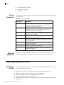
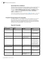
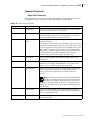
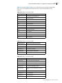
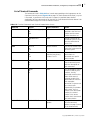
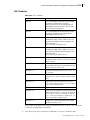
Revision
History
Table 4-1 Revision History of Manual
Edition
Date
Comments
A
April 2005
Initial production release
B
December 2005
Split original manual into two volumes
Added Utah Scientific RCP-1 and Utah-12
protocol support
Added information concerning Ethernet clients
support
Added NVISION protocol support
C
Applications
September
2006
D
October 2006
Transferred references to individual protocols
supported
E
March 2007
Updated DIP switch settings chart
F
May 2011
Combined contents of EDGE Manual and
Protocol Translation Functions Manual
Updated minor DIP Switch info in the Frame
Configuration chapter
Edge protocol gateway are ideal for operations where professional end users require a small,
flexible protocol translator to provide interoperability between routers and control systems
made by more than one manufacturer.
Edge protocol gateway are perfect for
Television production facilities
Cable operators
Production and post-production facilities
Copyright © 2005-2011, Harris Corporation
vi
Preface
Preface
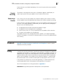
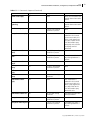
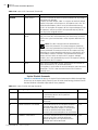
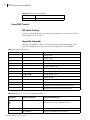
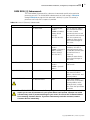
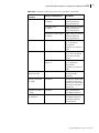
Writing
Conventions
Outside broadcast vans/trucks
DBS satellite operations
Webcasters
To enhance your understanding, the authors of this manual have adhered to the following
text conventions:
Table 4-2 Writing Conventions
Term or
Convention
Description
Bold
Indicates dialog boxes, property sheets, fields, buttons,
check boxes, list boxes, combo boxes, menus, submenus,
windows, lists, and selection names
Italics
Indicates E-mail addresses, the names of books or
publications, and the first instances of new terms and
specialized words that need emphasis
CAPS
Indicates a specific key on the keyboard, such as ENTER,
TAB, CTRL, ALT, or DELETE
Code
Indicates variables or command-line entries, such as a DOS
entry or something you type into a field
>
Indicates the direction of navigation through a hierarchy of
menus and windows
hyperlink
Indicates a jump to another location within the electronic
document or elsewhere
Internet address
Indicates a jump to a Web site or URL
Indicates important information that helps to avoid and
troubleshoot problems
Obtaining
Documents
Documents can be viewed or downloaded from the Harris Broadcast support web portal.
Alternatively, contact your Customer Service representative to request a document.
Unpacking/Shipping Information
This product was carefully inspected, tested, and calibrated before shipment to ensure years
of stable and trouble-free service.
Unpacking a
Product
1
Check equipment for any visible damage that may have occurred during transit.
2
Confirm that you have received all items listed on the packing list.
3
Contact your dealer if any item on the packing list is missing.
4
Contact the carrier if any item is damaged.
5
Remove all packaging material from the product and its associated components before you
install the unit.
Copyright © 2005-2011, Harris Corporation
Edge
Frame and Firmware Installation, Configuration, and Operation Manual
vii
Keep at least one set of original packaging, in the event that you need to return a product
for servicing.
Product
Servicing
Returning a
Product
This product is not designed for field service. All hardware upgrades, modifications, or
repairs require you to return your product to the Customer Service center.
In the unlikely event that your product fails to operate properly, please contact Customer
Service to obtain a Return Authorization (RA) number, then send the unit back for servicing.
Keep at least one set of original packaging in the event that a product needs to be returned
for service. If the original package is not available, you can supply your own packaging as
long as it meets the following criteria:
The packaging must be able to withstand the product’s weight.
The product must be held rigid within the packaging.
There must be at least 2 in. (5 cm) of space between the product and the container.
The corners of the product must be protected.
Ship products back to us for servicing prepaid and, if possible, in the original packaging
material. If the product is still within the warranty period, we will return the product prepaid
after servicing.
Standards
Appendix A, Safety Precautions, Certifications and Compliances contains product
compliance and safety standards.
Safety
Carefully review all safety precautions to avoid injury and prevent damage to this product or
any products connected to it. If this product is rack-mountable, it should be mounted in an
appropriate rack using the rack-mounting positions and rear support guides provided. It is
recommended that each frame be connected to a separate electrical circuit for protection
against circuit overloading. If this product relies on forced air cooling, it is recommended
that all obstructions to the air flow be removed prior to mounting the frame in the rack.
If this product has a provision for external earth grounding, it is recommended that the
frame be grounded to earth via the protective earth ground on the rear panel.
You will find a complete list of safety precautions in Appendix A.
IMPORTANT! Only qualified personnel should perform service procedures.
Copyright © 2005-2011, Harris Corporation
viii
Preface
Preface
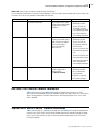
Safety Terms
and Symbols
in this
Manual
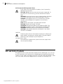
WARNING
Statements identifying conditions or practices that may result in
personal injury or loss of life. High voltage is present.
CAUTION
Statements identifying conditions or practices that can result in
damage to the equipment or other property.
Restriction on Hazardous Substance (RoHS) Compliance
Directive 2002/95/EC—commonly known as the European Union (EU) Restriction on
Hazardous Substances (RoHS)—sets limits on the use of certain substances found in
electrical and electronic equipment. The intent of this legislation is to reduce the amount of
hazardous chemicals that may leach out of landfill sites or otherwise contaminate the
environment during end-of-life recycling. The Directive, which took effect on July 1, 2006,
and refers to the following hazardous substances:
Lead (Pb)
Mercury (Hg)
Cadmium (Cd)
Hexavalent Chromium (Cr-V1)
Polybrominated Biphenyls (PBB)
Polybrominated Diphenyl Ethers (PBDE)
According to this EU Directive, all products sold in the European Union will be fully
RoHS-compliant and “lead-free.” (See our website for more information on dates and
deadlines for compliance.) Spare parts supplied for the repair and upgrade of equipment
sold before July 1, 2006 are exempt from the legislation. Equipment that complies with the
EU directive will be marked with a RoHS-compliant emblem, as shown in Figure 4-1
Figure 4-1 RoHS Compliance Emblem
Waste from Electrical and Electronic Equipment (WEEE) Compliance
The European Union (EU) Directive 2002/96/EC on Waste from Electrical and Electronic
Equipment (WEEE) deals with the collection, treatment, recovery, and recycling of electrical
and electronic waste products. The objective of the WEEE Directive is to assign the
responsibility for the disposal of associated hazardous waste to either the producers or users
of these products. Effective August 13, 2005, producers or users are required to recycle
electrical and electronic equipment at end of its useful life, and may not dispose of the
equipment in landfills or by using other unapproved methods. (Some EU member states
may have different deadlines.)
Copyright © 2005-2011, Harris Corporation
Edge
Frame and Firmware Installation, Configuration, and Operation Manual
ix
In accordance with this EU Directive, companies selling electric or electronic devices in the
EU will affix labels indicating that such products must be properly recycled. (See our website
for more information on dates and deadlines for compliance.) Contact your local sales
representative for information on returning these products for recycling. Equipment that
complies with the EU directive will be marked with a WEEE-compliant emblem, as shown in
Figure 4-2.
Figure 4-2 WEEE Compliance Emblem
Copyright © 2005-2011, Harris Corporation
x
Preface
Preface
Copyright © 2005-2011, Harris Corporation
1
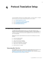
1
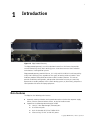
Introduction
Figure 1-3 Edge Protocol Gateway
The Edge protocol gateway is a multiuse platform housed in a 1RU frame that provides
external connectivity to any Harris routing system. It translates between Harris and other
manufacturers’ routing control systems.
Edge protocol gateways provide Ethernet, X-Y serial, and RS-232/RS-422 serial connectivity
to any Harris routing system, regardless of the type(s) of routing switcher involved. These
hardware products also provide connections to other vendors’ products. This manual
provides installation, configuration, and operation information necessary to successfully
operate other vendor’s products within a Harris routing system; or, alternatively, to operate a
Harris product with other third party equipment.
Main Features
The Edge has the following main features:
Automatic recovery of broken and restored connections whether due to power supply
failures, Ethernet communications failures, or physical medium errors
Support for the following communications media:
Harris X-Y bus loop-through (75Ω coax) port
RJ-45 Ethernet port
9-pin D-selectable RS-232 or TIA/EIA-422-B
Auto-sensing 110 VAC to 240 VAC power
Copyright © 2005-2011, Harris Corporation
2
Chapter 1
Introduction
Supports up to 20 Ethernet clients using any combination of different protocols (such
as 10 virtual X-Y and 10 Telnet)
Alarm convection
Universal power supply
Protocol translation support
The Edge provides bidirectional translation of certain third-party routing devices as well as
unidirectional (control of Harris or third party routing devices) support for Harris serial
terminal protocol.
The Edge also supports these protocols for device configuration:
Harris serial terminal protocol
Harris pass-through protocol
Control Features
The Edge is compatible with all existing Harris routers and remote control panels. Frames
include the following control options:
Two standard serial ports for communication to/from computers and automation
systems (configurable for RS-232 or RS-422) with support for up to 115K baud serial
communications
One looping coaxial (X-Y) port for connecting to remote control panels and other
routers
An Ethernet port
A firmware- or software-based control system
Operating Mode
A DIP switch (pole 6 on SW3) controls how the two Edge serial control ports are configured.
When set to OFF, the Edge behaves like a typical Harris router (that is, Harris Terminal mode
for both serial ports). When set to ON, the Edge uses the programmed port configuration
(set through the terminal or via RouterMapper). This setting allows use of non-Harris
product protocols.
Software Control Applications
You can configure the Edge directly using Harris terminal protocol, or via the CCS Navigator
or RouterMapper™ software configuration utility.
Harris Terminal Protocol
Harris terminal protocol is useful as an interface to a router to check the status of the router
and to change the crosspoints. A serial port or Telnet connection and terminal emulation
software are all that are needed to establish communications between a terminal and a
router. You can find information on the following topics in the Edge Frame and Firmware
Installation, Configuration, and Operation Manual:
Using the terminal protocol specifically with the Edge
Copyright © 2005-2011, Harris Corporation
Edge
Frame and Firmware Installation, Configuration, and Operation Manual
Instructions on serial port configuration
Instructions on Ethernet port configuration
3
RouterMapper
RouterMapper is an easy-to-use Windows®-based application for programming
RouterWorks®, other router frames, control panels, and the Opus™ master controller. You
can find instructions for adding and editing Edge configurations in the RouterMapper
Configuration Utility Reference Guide.
There are several software options available to control your Harris products through the
Edge. For information about these software products, contact the Sales Department or see
our website.
CCS Navigator™ (v. 2.0 or later)
The CCS Navigator software provides the graphical tools that will enable you to create
easy-to-use graphical pages that visually represent your network’s many devices, systems,
and environments. These graphical pages allow you to consolidate and ease network-wide
status monitoring, leading to more efficient deployment of human resources for monitoring
and troubleshooting tasks. You can find instructions for adding and editing Edge
configurations in Volume 6 of the Navigator Advanced Graphical Navigation Application
User Manual.
RouterWorks
RouterWorks router control software provides a graphical user interface for the entire line
of Harris signal routers. RouterWorks software may be used as the only controlling device in
a system, or it may be used in conjunction with traditional hardware control panels.
Multiple RouterWorks control stations may control the same routing system. RouterWorks
continually monitors the routing system and reports all changes in the status of the system,
regardless of the type of controlling device that initiated the change.
Copyright © 2005-2011, Harris Corporation
4
Chapter 1
Introduction
Copyright © 2005-2011, Harris Corporation
5
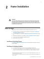
2
Frame Installation
WARNING
Potentially lethal voltages are present within the frame during normal operation.
Disconnect all power cords from the frame before you remove the top panel. Do
not apply power to the frame while the top is open unless the unit is being serviced
by properly trained personnel.
Before You Begin
Before you can begin the protocol translation configuration procedures, you must
Install and configure your protocol-specific equipment as described in Installing and
Configuring Hardware on page 5
Install your Edge frame as described in Edge Frame Installation Information on page
6
Configure your Edge frame as described in Frame Configuration Details on page 17
If necessary, install the appropriate protocol firmware1
Activate your firmware license1
Installing and Activating Firmware
See Chapter 4, Protocol Translation Setup for information about activating the firmware
for your protocol.1
Installing and Configuring Hardware
See page 6 for information on how to install and configure an Edge frame.
See the Grass Valley Group Series 7000 Configuration Manual for specific information
on how to install and configure a GVG-SMS 7000 Series signal management system.2
1 If
you ordered the protocol firmware at the same time as your original Edge product purchase, it will
be factory-installed and -activated.
2 GVG SMS-7000 Jupiter routing control systems are products of Thomson Grass Valley, headquartered
in Paris, France.
Copyright © 2005-2011, Harris Corporation
6
Chapter 2
Frame Installation
See the Jupiter FM 3000 Installation and Operating Manual for specific information on
how to install and configure a Jupiter router switcher.2
See the NVISION NV6000 and NV8000 Series Universal Routers Users Guide for specific
information on how to install and configure an NVISION routing switcher.1
See the pertinent PESA installation and operation manual for specific information on
how to install and configure a particular PESA routing switcher.2
See the pertinent Pro-Bel installation and operation manual for specific information on
how to install and configure a particular Pro-Bel routing switcher.3
Edge Frame Installation Information
Unpacking Equipment
The Edge package includes the items listed below. Confirm that you have received all items
listed on the packing list. Contact your dealer if any item on the packing list is missing.
One Edge product
One Edge Installation and Configuration Manual
One desktop power supply
Optional redundant power supply (if ordered)
Pre-Installation Checklist
This product was carefully inspected, tested, and calibrated before shipment to ensure years
of stable and trouble-free service.
1
Check equipment for any visible damage that may have occurred during transit.
2
Confirm that you have received all items listed on the packing list.
3
Contact your dealer if any item on the packing list is missing.
4
Contact the carrier if any item is damaged.
5
Remove all packaging material from the product and its associated components before you
install the unit.
If your equipment was damaged during transit, see Returning a Product on page vii to
determine what you must do to return the equipment to us.
Examining Equipment
The following sections describe the physical components of the Edge. The descriptions will
provide you with the information you need to make sure these components operate
correctly after installation is complete.
1 NV
routing control systems are products of NVISION Inc., headquartered in Grass Valley, California.
PESA routing switchers are products of QuStream Corporation, headquartered in Toronto, Canada.
3 Pro-Bel routing switchers are products of Pro-Bel Ltd., headquartered in Reading, Berkshire, UK.
2
Copyright © 2005-2011, Harris Corporation
Edge
Frame and Firmware Installation, Configuration, and Operation Manual
7
Modular Components
The components installed in the Edge frame are as follows:
Power/Alarm and Link LEDs
Module Interconnect (MI)
Flash Memory Module
Resource Module
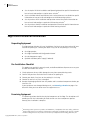
Power/Alarm and Link LEDs
A power/alarm LED and a link LED are present on all control modules (see Figure 2-4).
Figure 2-4 Power/Alarm and Link LEDs
The power/alarm LED is illuminated green when power is present. If the power LED is
not lit, one or more of the supply rails on the module is invalid.
The link LED is illuminated yellow when an Ethernet connection is made and
maintained.
Copyright © 2005-2011, Harris Corporation
8
Chapter 2
Frame Installation
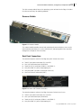
Module Interconnect (MI)
Figure 2-5 Module Interconnect
The module interconnect (MI) provides communications, power conversion, and reference
conditioning for the resource module. It also provides control connectivity between the
resource module and the back panel. The MI monitors and controls the single relay alarm
for power loss, fan failure, or other alarms.
Flash Memory Module
Figure 2-6 Flash Memory Module
Copyright © 2005-2011, Harris Corporation
Edge
Frame and Firmware Installation, Configuration, and Operation Manual
9
The flash memory module houses the operating system software for the Edge. It includes
the software necessary for updating protocols.
Resource Module
Figure 2-7 Resource Module
The resource module provides control and monitoring of communications, access to the
communication connectors (X-Y, serial, and Ethernet), and configurable items accessible
through the serial port or Telnet interface.
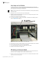
Back Panel Connections
The control and power section of the Edge rear panel includes these items:
Two DC input power connectors (PS1 and PS2)
One 3-pin alarm/comm port (ALM/COM)
Two 9-pin RS-232 serial ports (SERIAL 1 and SERIAL 2)
One pair of BNC X-Y ports (single looping X-Y)
One pair of BNC sync ports (reserved for future use)
One RJ-45 Ethernet connection (ENET)
Figure 2-8 Power and Control Connections
The control and power section of the Edge II rear panel includes these items:
Two DC input power connectors (PS1 and PS2)
One 3-pin alarm/comm port (ALM/COM)
Two 9-pin RS-232 serial ports (SERIAL 1 and SERIAL 2)
One pair of BNC X-Y ports (single looping X-Y)
Copyright © 2005-2011, Harris Corporation
10
Chapter 2
Frame Installation
One pair of BNC X-Y/SBUS ports
Two RJ-45 Ethernet connections (ENET)
Alarm/Comm Port
The 3-pin alarm/comm port reports alarms as they occur in the frame.
Pin 1 (labeled “+”) – Normally open/normally closed (jumper selectable)
“Normally closed” is shorted with the common (closed) when an alarm condition
does not exist and the frame is powered.
The default operation of the alarm relay is “normally open.”
“Normally open” is shorted with the common (closed) when an alarm condition
exists.
Pin 2 (GND) – Relay common
Pin 3 (labeled “–”) – Reserved for future use
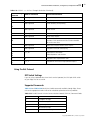
The alarm port provides indication of these alarm conditions:
Table 2-3 Alarm Conditions
Alarm Condition
Description
PS Fail
Alarm asserted in the event of a power supply failure
(in systems with multiple power supplies, the alarm
will be asserted if any power supply fails)
The alarm relay circuitry has been designed so the relays are energized when the alarm
condition does not exist. If a relay fails or if the circuit controlling a relay fails, the relay will
de-energize, which will cause the corresponding alarm to be asserted. If the frame loses
power, the alarm relay will become de-energized, and the alarm condition will be asserted.
The relay is energized when power is applied to detect when power is lost and to allow the
alarm to be asserted.
Serial Connections
Note: Table 2-4 on page 14 shows the connector pin assignments for a RS-232 cable
connection. Table 2-5 on page 14 shows the connector pin assignments for an RS-422
cable connection.
One of the many powerful features of a Harris router control system is its ability to use a
serial port to access an entire system. The serial port, in effect, is the control gateway to the
entire routing system.The serial port allows external control of the Edge by a computer, user,
or automation system via a serial connection using RS-232 or RS-422. The port is configured
by DIP switches on the resource module (see Figure 3-14 on page 20), or by settings
selectable from a terminal screen (see “Terminal Operations” in the Protocol Translation
Functions Configuration and Operation Manual).
X-Y Port
The X-Y control bus is a high speed serial interface by which Harris routers and control
panels are interconnected via standard 75Ω video coax cable. The ends of the X-Y bus must
be terminated using standard 75Ω video terminators.
The Edge features one looped-through port (two BNC connectors). If either of the BNCs is
used, the other associated X-Y port connection must be terminated with a 75Ω BNC
terminator or connected to another device’s X-Y port. For example, it is not necessary
to terminate either of the BNCs if neither is used.
Copyright © 2005-2011, Harris Corporation
Edge
Frame and Firmware Installation, Configuration, and Operation Manual
11
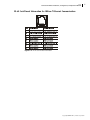
Ethernet Connection
The Ethernet connection provides high-speed links for configuration, control, and
monitoring of the complete routing system. The Ethernet connection uses 10Base-T wiring.
Figure 2-11 on page 15 shows the RJ-45 jack pinout information for 10Base-T Ethernet
communication
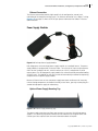
Power Supply Modules
Figure 2-9 Desktop Power Supply Module
Each Edge comes with a desktop power supply module as a standard feature. The power
supply module is equipped with a universal input. The universal AC input version operates
from 100 VAC through 240 VAC, which it converts to 15V DC, and provides 70 W of
output power. The desktop power supply module has a thermostatically-controlled cooling
fan built into it. The cooling fan will turn on and off automatically to control the operating
temperature of the power supply module.
Because all frames have at least two power supply connectors and because all necessary
current sharing components are located internally to the frame, you only need to plug in a
second desktop power supply for redundancy.
Optional Power Supply Mounting Tray
Figure 2-10 Power Supply Mounting Tray
The power supply mounting tray allows you to mount up to seven 1RU desktop power
supplies. This mounting tray can be forward- or rear-mounted into a regular frame rack.
Contact your Sales representative for more information about this option.
Copyright © 2005-2011, Harris Corporation
12
Chapter 2
Frame Installation
Installing Hardware
CAUTION
Test your system before its final installation. Make sure you verify its
configuration, cabling, and proper system operation.
Siting Requirements
Ensuring Adequate Rack Space
The Edge frame is designed for mounting into a standard width 19-in. (48.3-cm) rack.
Frames are secured to the rack with standard front-mounting ears built into the chassis.
Make sure to provide adequate space behind the mounting ears, and appropriate clearance
for the connecting cables at the rear of the frame.
Ensuring Proper Temperature and Ventilation
An ambient temperature should be maintained between 32°F (0°C) and 122°F (50°C) at a
relative humidity of 10%-90% (non-condensing). No special cooling arrangements are
necessary, but make sure to prevent excessive ambient heat rise in closed, unventilated
equipment racks. To ensure proper ventilation, keep the front panel of the frame closed
during operation; otherwise, the frame could overheat.
Meeting Electrical Requirements
The Edge frame accepts one desktop power supply unit (PSU). The frame is prewired to
accept a second, optional power supply for power backup. Their power consumption is
nominally 65VA. A fully loaded frame will operate with a single power supply.
Maximum Power Dissipation
These ratings refer to the total module power consumption (excluding that of the power
supply) allowable within the Edge frame. The limits are based on the ability of the unit to
dissipate heat over a temperature range of 32°F to 122°F (0°C to 50°C).
Voltage Selection
The Edge frame does not have a voltage selector switch. The desktop power supply has a
continuous input range of 100 VAC to 240 VAC.
Protective Ground
Since the desktop power supply does not present a shock hazard, the Edge frame does not
have a protective safety earth ground.
Mounting and Installing
The following tools and equipment are recommended for frame installation:
One standard 19-in. (0.4-m) rack
Copyright © 2005-2011, Harris Corporation
Edge
Frame and Firmware Installation, Configuration, and Operation Manual
One medium Phillips screwdriver
Four 10/32 Phillips-head rack mount screws
One of the following
Standard 10 Mbps 10Base-T Ethernet cable segment no longer than 382.08 ft (100
m)
RS-232 or RS-422 cable segment; no longer than 50 ft (15 m) for RS-232, and
2,000 ft (610 m) for RS-422
13
Mounting Requirements
The Edge frame can be mounted in a standard width 19-in. (48.3 cm) rack using four 10/32
Phillips-head mounting screws. The back of the frame does not need to be supported. The
frame can be mounted in either the front or the rear of the rack, thereby providing more
efficient use of your equipment housing space. The rack ears can be attached to the frame
in either direction, thereby allowing you flexible mounting options. The 1RU mounting
frame requires one unit of rack space, that is, 1.75 in. (44 mm) of standard rack space. The
depth from the mounting surface is 5.25 in. (13.3 cm).
Edges are installed in the control line.
The maximum allowable distance for each segment of the X-Y coaxial cable run is
2,000 ft (609 m).
The maximum for each RS-422 segment is 2,000 ft (609 m).
There is no limit to the number of control devices added to the X-Y control bus.
Installation Procedures
The Edge can be installed anywhere within a routing system. General installation
procedures are outlined below.
1
Mount the frame in an rack that provides power and cooling facilities. The frame is
designed for mounting in a standard equipment rack.
2
Align the frame so that all 4 screw holes in the mounting ears match up with those in the
rack. (Adjustable ears on each side of the frame allow adjustable depth placement of the
frame within the rack.
3
Secure the frame to the rack with the rack screws and washers.
4
Connect the control device(s) to the appropriate port (X-Y, serial, Ethernet, and so forth) on
the frame’s rear panel.
5
If the Edge will be used in a multiple frame system, connect the additional frames using port
the appropriate scheme (X-Y, Ethernet, and so forth.).
6
If the Edge is at the end of the X-Y bus, terminate the other X-Y connector with a coaxial
75Ω termination.
7
Connect the 3-pin alarm port to the appropriate alarm device(s), as necessary.
8
Plug the desktop power supply into its corresponding Edge power supply port.
9
Connect the power supply to a power source. When power is applied to the Edge, it starts
up automatically.
Copyright © 2005-2011, Harris Corporation
14
Chapter 2
Frame Installation
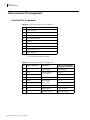
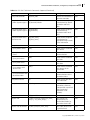
Cable Connector Pin Assignments
Serial Port Pin Assignments
Table 2-4 RS-232 Signal Format Pin Assignments
Pin
Function
1
Frame Ground
2
RxD (Data received by router)
3
TxD (Data sent by router)
4
Data Terminal Ready*
5
Ground
6
Data Set Ready (DSR)*
7
Request to Send (RTS)**
8
Clear to Send (RTS)**
9
Frame Ground
* Pins 4 and 6 connected internally.
** Pins 7 and 8 connected internally
Table 2-5 RS-422 Signal Format Pin Assignments
Pin
Signal (Tributary)
Description
Connection to Remote
Computer (Controller)
1
FG
Frame Ground
Frame Ground
2
Ta (Tx-)
Ra (Rx-)
7
Tb (Tx+)
Transmitted Data
(Twisted Pair)
6
Tc
Received Data Shield
Received Data Shield
8
Ra (Rx-)
Ta (Tx-)
3
Rb (Rx+)
Received Data
(Twisted Pair)
4
Rc
Transmitted Data Shield
Transmitted Data Shield
9
FG
Frame Ground
Frame Ground
5
SP
(Not Connected)
(Not Connected)
Copyright © 2005-2011, Harris Corporation
Rb (Rx+)
Tb (Tx+)
Edge
Frame and Firmware Installation, Configuration, and Operation Manual
15
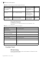
RJ-45 Jack Pinout Information for 10Base-T Ethernet Communication
Figure 2-11 RJ-45 Jack Pinout Information
Copyright © 2005-2011, Harris Corporation
16
Chapter 2
Frame Installation
Copyright © 2005-2011, Harris Corporation
17
3
Frame Configuration
Note: See Chapter 5, Protocol Translation Configuration for protocol configuration
information. See Chapter 2, Frame Installation for Edge frame installation information.
Frame Configuration Details
Preparing for Configuration
Before you configure the Edge frame , you must have the following items:
A PC connected to a local area network running one of the following:
HyperTerminal1 or other terminal emulation program
Telnet program
Configuration utility software such as Navigator or RouterMapper
Note: To configure Name support, an Ethernet connection is required.
An Edge product installed and connected to the local area network
A standard 10 Mbps 10Base-T RJ-45 Ethernet cable segment or a null modem cable for
serial port operations
Configuring the Alarm Jumper and DIP Switches
There are two items that may need to be configured before operating the resource module
(if settings other than the defaults are desired):
The Alarm jumper on the (MI) board (Figure 3-12 on page 18 shows the location of the
alarm port jumper on the MI module.)
Three DIP switches on the front of the resource module. (Figure 3-13 on page 19 shows
the location of the DIP switches on the Edge resource module. Figure 3-14 on page 20
provides a summary of the functions of each DIP switch.)
1 HyperTerminal,
a product of Hilgraeve Inc., is a communications applet that ships with Windows 95/
98 and Windows NT 4.0.
Copyright © 2005-2011, Harris Corporation
18
Chapter 3
Frame Configuration
Alarm Jumper on the MI Module
The Alarm jumper sets the normally open/normally closed operation of the alarm port.
Unless otherwise noted, the frame is shipped from the manufacturing facility with the alarm
port configured for normally open (NO) operation.
Note: To switch the alarm port from normally closed operation to normally open operation,
follow these steps:
1
Unplug the frame so that it does not receive electrical power.
2
Unscrew the screws on the front panel. (The screws in the front panel are captive. Do not
separate them from the front panel.)
3
Gently pull the front panel away from the frame.
4
Tilt the front panel down to expose the MI module. The location of the NO/NC jumper is
shown in Figure 3-12 on page 18.
Figure 3-12 Location of NO/NC Jumpers for the Alarm Port
5
Using a pair of tweezers or needle-nosed pliers, pull the jumper pack loose from its location.
6
Push the jumper pack onto the pins of the desired location.
7
Tilt the front panel back up to cover the exposed front of the router.
8
Reattach the front panel to the Edge frame.
DIP Switches on the Resource Module
The resource module has three banks of 8-pole DIP switches that are accessible from the
front of the frame. To configure the DIP switches, follow these steps:
1
Unscrew the screws on the front panel. (The screws in the front panel are captive. Do not
separate them from the front panel.)
Copyright © 2005-2011, Harris Corporation
Edge
Frame and Firmware Installation, Configuration, and Operation Manual
2
Gently pull the front panel away from the frame.
3
Tilt the front panel down to expose the DIP switches.
19
Figure 3-13 DIP Switch Location and Identification
Note: If you want your Edge settings to match the factory defaults, you do not need to
make any further changes.
4
Set the DIP switches as shown in Figure 3-14 (page 20).
SW1 provides DIP switches for functions related to frame ID and operating mode.
SW2 DIP switch functions are reserved for future use.
SW3 provides DIP switches for these functions related to serial port configuration:
Serial port protocol configuration mode
This setting determines whether serial ports 1 and 2 are configured using SW3 DIP
switch or software settings configured from the terminal. The setting should
normally be set to the software mode (SW3-6 On) unless the Edge is not being
used for protocol translation. If you select the SW3 DIP switch setting mode,
settings for serial ports 1 and 2 are determined by the settings made on SW3 and
both serial ports are forced to Harris protocol only. If the ports need to be
configured individually, or protocol translation is required, the software setting
mode should be selected.
RS-422 termination
RS-422 multidrop mode
Multi-drop addressing mode
Serial port protocol
Serial port baud rate
5
Tilt the front panel back up to cover the exposed front of the router.
6
Reattach the front panel to the Edge frame.
Copyright © 2005-2011, Harris Corporation
20
Chapter 3
Frame Configuration
Figure 3-14 DIP Switch Configuration
Setting Up the Power Supply Module
Note: You may see an arc within the connector internally as the power supply connection is
made. This is normal.
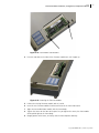
Push the power supply module plug into the PS1 connector (see Figure 3-15) until the
fastener clips. To make sure the power supply module is plugged in, gently pull on the plug
cable to make sure that the fastener is secure. It should not pull out easily.
Copyright © 2005-2011, Harris Corporation
Edge
Frame and Firmware Installation, Configuration, and Operation Manual
21
If you are using a second power supply module, plug it into the PS2 connector (see
Figure 3-15). Follow the same procedure as for the first power supply.
Figure 3-15 PS1 and PS2 Power Supply Connector Locations
Copyright © 2005-2011, Harris Corporation
22
Chapter 3
Frame Configuration
Copyright © 2005-2011, Harris Corporation
23
4
Protocol Translation Setup
Setting up protocol translation for your hardware product is a multi-part process. This guide
provides step-by-step instructions for completing each part of the process.
Part 1: Determining What To Do First
Part 2: Reviewing Pre-Installation Information
Part 3: Installing the Protocol Firmware
Part 4: Entering the License Key
Pre-Installation Information
The Edge hardware products provide Ethernet, X-Y serial, and RS-232/RS-422 serial
connectivity to any Harris routing system, regardless of the type(s) of Harris routing switcher
involved. It also provide connections to other vendors’ products. This chapter provides
information necessary to successfully install the appropriate firmware and a license key for
your selected protocol.
Edge hardware products provide bidirectional translation of the following router control
protocols:
Harris pass-through protocol
GVG SMS-7000 protocol
Jupiter ASCII and ESswitch protocol
NVISION serial and Ethernet protocols
PESA CPU Link Protocol No 1 (P1) protocols
Pro-Bel SW-P-02 and SW-P-08 protocols
Utah Scientific RCP-1 protocol
Determining What To Do First
If you ordered the GVG, Jupiter, NVISION, Pro-Bel, or Utah protocol firmware separately from
your original hardware purchase, you must install updated firmware. Review the
Equipment You Will Need and Pre-Installation Checklist sections that follow, and then
go to Installing the Protocol Firmware on page 24.
Copyright © 2005-2011, Harris Corporation
24
Chapter 4
Protocol Translation Setup
If you ordered the GVG, Jupiter, NVISION, Pro-Bel, or Utah protocol firmware at the same
time as your original hardware purchase, it will be factory-installed. You will not need to
reinstall the firmware; however, you will need to configure it. See Chapter 5, Protocol
Translation Configuration for more detailed information.
Equipment You Will Need
Before you begin this process, make sure you have the following equipment:
Edge frame
Personal computer
File transfer protocol (FTP) software installed on PC
A network-enabled system setup will usually have some version of FTP client software
installed. Refer to your operating system documentation for instructions on how to
perform the file transfer function for your particular setup. Alternatively, you can
download or purchase third-party FTP software.
Pre-Installation Checklist
Before you install and/or configure the firmware module:
1
Check the equipment for any visible damage that may have occurred during transit.
2
Confirm that all items listed on the packing list have been received.
3
Remove the anti-static shipping pouch and all other packaging material.
4
Keep the original packaging in case a product needs to be returned for service or shipped to
another location.
5
Check the PC to make sure that FTP client software is installed, and that you know how to
use the software correctly.
6
Make sure your hardware product has already been set up on your intranet or local area
network with a valid IP address.
Installing the Protocol Firmware
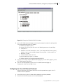
Determining the Size of Installed Flash RAM
1
Open a serial or Telnet terminal operation session.
2
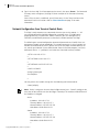
At the > prompt, type show fs, and then press <Enter>. The following information will be
displayed (the information displayed on your screen may vary from this example):
Copyright © 2005-2011, Harris Corporation
Edge
Frame and Firmware Installation, Configuration, and Operation Manual
25
Figure 4-16 Checking Flash Size
3
Check that the flash size is 16 MB. Edge hardware frames require a 16 MB flash RAM.
If the flash size is 4 MB, a new flash RAM module will be required. You will need to
determine the control board serial ID (see step 4).
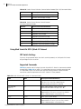
If the flash size is 16 MB, check the software code version (see Table 4-6).
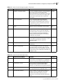
Table 4-6 Software Revision Versions for Edge Protocols
4
Protocol Option
Software Revision Version
GVG
2.51 or higher
Jupiter
2.72 or higher
NVISION
2.61 or higher
Pro-Bel
2.77 or higher
Utah
2.52 or higher
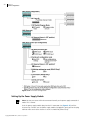
At the > prompt, type show rparm. The following information will appear. (the
information displayed on your screen may vary from this example):
Figure 4-17 Locations of Software Revision, Control Board Serial ID, and License ID Fields
If the existing flash size is 4 MB, a new flash RAM module is required.
Write down code number shown in the Control Board Serial ID field. (The
License ID field will not appear on Edge frames with a 4 MB flash.)
Copyright © 2005-2011, Harris Corporation
26
Chapter 4
Protocol Translation Setup
Go to step 5.
If the existing flash size is 16 MB but the version of code is less than v2.51, a new
flash RAM module is required.
Write down code number shown in the Control Board Serial ID field. (The
License ID field will not appear on Edge frames with firmware versions less
than v2.51.)
Go to step 5.
Note: The License ID is unique to each Edge frame. License keys generated using one
frame's ID will not work for another frame. If a feature will be installed on several frames,
each frame's License ID will be required so that a separate key may be created for and
installed on each frame.
5
If the existing flash size is 16 MB and the software revision is v2.51 or higher:
Write down the code shown in the License ID field. Your Sales representative
will need this code to create a license key that enables the appropriate protocol
option.
Go to step 5.
Contact your Sales representative so that your protocol license key can be created. (Se our
website for a list of technical support locations and telephone numbers).
The License ID code and/or the Control Board Serial ID code will be necessary to
generate the license key number. Give this code and the frame serial number (located
at the rear of the frame on a sticker beginning with the characters LHTI) to your Sales
representative, and ask that a License Key be generated. If using the Control Board
Serial ID code, make sure you tell the Sales representative that you need a new
16 MB flash RAM with software version v2.51 or higher.
If you received a new 16 MB flash RAM module, go to Installing the Flash
Module on page 26.
If you did not need a new flash RAM module, go to Entering the License Key on
page 28.
Installing the Flash Module
When you receive the new 16 MB flash module, it will include the license key. Install the
new flash module into the frame as follows:
1
Unplug the frame so that it does not receive electrical power.
2
Unscrew the screws on the front panel. (The screws in the front panel are captive. Do not
separate them from the front panel.)
CAUTION
Some Edge front panel units do not have supporting hinges. Consequently, if the
front panel face plate is removed and not handled properly, it can fall with
sufficient force to dislocate and/or damage the ribbon cable attached to the
resource module connector. When removing the front panel, hold the face plate
firmly to ensure that it does not become damaged.
3
Tilt the panel cover down so that the flash module is visible.
Copyright © 2005-2011, Harris Corporation
Edge
Frame and Firmware Installation, Configuration, and Operation Manual
27
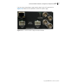
Figure 4-18 Flash Module Tabs Locations
4
Press the two tabs on the sides of the firmware module out, until it pops up.
Figure 4-19 Removing the Firmware Module
5
Pull out the existing firmware module and set it aside.
6
Insert the new firmware module into the card insert on the frame front cover.
7
Align the reassembled front module with the frame body.
8
Tighten the screws on the front of the panel. As you tighten the screws, the front module
will be pulled tight to the frame body.
9
Reapply power to the frame, and verify that the frame operates correctly.
Copyright © 2005-2011, Harris Corporation
28
Chapter 4
Protocol Translation Setup
Entering the License Key
1
Obtain your “soft” activation code from your Sales representative. This activation code,
consisting of fourteen characters, will be provided to you when you purchase the protocol
translation option.
2
Use any ASCII text editing program to create a file named license.txt.
3
As the first line in the license.txt file, enter the 14-digit license keycode. Do not include any
spaces or carriage returns.
4
Use an FTP program to copy the license.txt file from its original location to the Edge flash
module directory devfs:.
If you received a license file (license.txt) from us, go directly to step 4.
The frame is now set up for protocol translation configuration.
Copyright © 2005-2011, Harris Corporation
29
5
Protocol Translation
Configuration
Configuring for Use with Harris Protocols
Two separate serial control ports are used to control Edge from an external computer or
automation system. Either serial port may be used to monitor the system configuration,
determine the current status of crosspoint connections, change crosspoint connections in
any matrix, and setup pre-programmed crosspoint takes sequences (salvos). In a system
involving multiple frames the commands entered into the serial port on one frame are sent
to the other frames in the system via the X-Y control bus. Any serial control port in the
routing system can be used for control or status of the entire system.
Note: DIP switches are set to “0” as the default setting
Both serial control ports are preset at the manufacturing facility with identical default DIP
switch settings. If you want your Edge settings to match these defaults, you do not need to
make any further changes. If you do want to switch from the default settings (for example,
to use a different protocol), you only need to make the changes once. The Edge uses the
changed settings until you switch them again. DIP switch SW3 (see Figure 3-14 on page 20)
provides DIP switches for the functions related to serial port configuration.
Configuring for Translating Protocols
The Edge may be used to translate from Harris protocols to other third-party protocols. The
commands used to configure protocol translation and to view the Edge's current protocol
configuration can be displayed by typing SHOW MENU P at the Command prompt. See
page 83 for a list of the Protocol command line options.
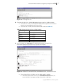
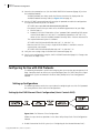
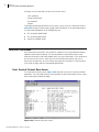
You can use the SHOW PORTS command at any time to view the configuration for all ports
that are loaded when you start the Edge.
Copyright © 2005-2011, Harris Corporation
30
Chapter 5
Protocol Translation Configuration
Figure 5-20 Example of SHOW PORTS Window
The full configuration table may be too long for standard terminal emulators to show in one
screen. To display a particular port’s configuration, use the GET ENET and GET SERIAL
commands.
Configuring for Use with Serial Protocol
Note: If both serial ports are configured for protocol translation, the Harris Telnet interface
may be used. Alternatively, the SW3 pole 6 switch may be set to OFF temporarily to allow
configurations.
Serial ports support one active protocol at a time. To configure a serial port's protocol:
1
Ensure DIP switch 3, pole 6, is ON to enable terminal-based configuration.
2
Determine which serial port (1 or 2) use the selected protocol.
3
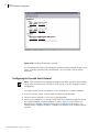
Determine the protocol to use. (Use the SHOW PROTOCOLS command [(page 83] to view
the available protocols.) Available protocols are shown under the Serial Interfaces list
displayed by the Available Protocol Summary Table (see Figure 5-21 on page 31). The
example shown in Figure 5-21 shows 7 available serial interfaces and 7 available Ethernet
interfaces.
Copyright © 2005-2011, Harris Corporation
Edge
Frame and Firmware Installation, Configuration, and Operation Manual
31
Figure 5-21 Example of SHOW PROTOCOLS Window
4
Use the SET SERIAL command (page 83) to assign the protocol to enable the configuration.
The required command syntax is as follows:
SET SERIALx opt=x[opt=x,opt=x]
For example, assume that you want to set the following parameters for your Edge:
Serial port = 2
Protocol = GVG SMS-7000 Native “server” (GVG control of Harris router system);
shown as item 2 on the Available Protocol Summary Table – Serial Interfaces list
Baud rate = 38400
Communications mode = RS-232
The required command syntax is as follows:
SET SERIAL2 PROTOCOL=2,BAUD=38400,MODE=RS232
5
Verify the new settings using the SHOW PORTS (page 83), the GET ENET (page 83), or the
GET SERIAL (page 83) command.
6
Save the new configuration using the SAVE SYSCONFIG command (page 83).
Changes take effect after the Edge is reset.
Configuring for Use with Ethernet Protocols
Ethernet connections may support more than one active protocol at any given time. To
enable an Ethernet protocol:
1
Ensure DIP switch 3, pole 6 is ON to enable support for non-Harris protocols.
2
Determine which Ethernet port uses the selected protocol.
Copyright © 2005-2011, Harris Corporation
32
Chapter 5
Protocol Translation Configuration
3
Determine the protocol to use. (Use the SHOW PROTOCOLS command [page 83] to view
the available protocols.)
Available protocols are shown under the Ethernet Interfaces list displayed on the
Available Protocol Summary Table (see Figure 5-21 on page 31).
4
Use the SET ENET command (page 83) to assign the protocol to enable the configuration.
The required command syntax is as follows:
SET ENETx opt=x opt=###.###.###.###,###.###,###.###
For example, assume that you want to set the following parameters for your Edge:
Ethernet port = 1
Protocol = GVG SMS-7000 Native “client” protocol (Harris controlling GVG routers
with MCPU IP address at 192.168.7.11 and backup controller at 192.168.7.12);
shown as item 4 on the Available Protocol Summary Table – Ethernet Interfaces list
The required command syntax is as follows:
SET ENET1 PROTOCOL4=ON SERVER=192.168.7.11,192.168.7.12
Note that for GVG Client, if only a single MCPU IP address is available it must be
entered twice; for example:
SET ENET1 PROTOCOL4=ON SERVER=192.168.7.13,192.168.7.13
5
Verify the new settings using the SHOW PORTS command (page 83).
6
Save the new configuration using the SAVE SYSCONFIG command (page 83). Changes take
effect after the Edge is reset.
Configuring for Use with GVG Protocols
The following information is specific to setting up your system so that you can operate it via
Edge. Complete details on how to set up and configure your GVG SMS-7000 Series Signal
Management System are located in the Grass Valley Group Series 7000 Configuration
Manual.
Setting up Configurations
The following sections outline the steps involved in configuring for use with GVG protocols
for setting Ethernet client and server configurations.
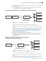
Setting Up the GVG Ethernet Client Configuration (Harris Controls GVG)
Figure 5-22 GVG Ethernet Client Configuration
Follow the steps for these operations in the Grass Valley Group Series 7000 Configuration
Manual:
1
Enable IP control of the GVG system (see “Configuring for the Network Remote End”).
Copyright © 2005-2011, Harris Corporation
Edge
Frame and Firmware Installation, Configuration, and Operation Manual
2
Enable levels that can be controlled through remote control interface (see “Configuring for
the Network Local End”).
3
Direct the Edge to connect to the GVG Master Control Processing Unit (MCPU) and backup
MCPU IP addresses (see “Pre-Configure New Coprocessors”).
33
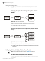
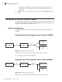
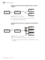
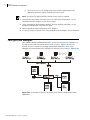
Setting Up the GVG Ethernet Server Configuration (GVG Controls Harris)
Harris
routing switcher
SMS 7000
MCPU client
GVG panel
GVG 7000
native
protocol
Edge:
7000 server
Harris
routing switcher
X-Y
Harris
remote control
panel
Harris routing system
controlled by SMS 7000
MCPU as an “alien matrix”
Figure 5-23 GVG Ethernet Server Configuration
Follow the steps for these operations as provided in the pertinent manuals:
1
Configure the Harris router (see the installation manual that applies to your specific Harris
router).
2
Using your configuration utility software, configure the Edge to reflect how you want the
router presented to the GVG MCPU (see Configuring for Name Support on page 51; see
Chapter 7, Supporting Level, Source, or Destination Names With Edge on page 87
for more detailed background information).
3
Configure Edge server protocol to listen for connections.
4
Configure the GVG MCPU for control of an alien matrix using GVG SMS-7000 protocol (see
“Configuration for Control of Alien Matrices” in the Grass Valley Group Series 7000
Configuration Manual).
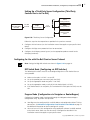
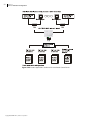
Setting Up a Third-Party Ethernet Server Configuration
(Third Party Controls Harris via GVG)
Harris
routing switcher
Harris or other
third-party control
system client
GVG 7000
native
protocol
Edge:
7000 server
X-Y
Harris routing system controlled
as if it were an “Internet interface”
of an SMS 7000 MCPU
Harris
routing switcher
Harris
remote control
panel
Figure 5-24 Third-Party Ethernet Server Configuration
Follow the steps for these operations as provided in the pertinent manuals:
1
Configure the Harris router (see the installation manual that applies to your specific Harris
router).
2
Using configuration utility software, configure the Edge to reflect how you want the router
presented to the GVG MCPU (see Configuring for Name Support on page 51; see
Copyright © 2005-2011, Harris Corporation
34
Chapter 5
Protocol Translation Configuration
Chapter 7, Supporting Level, Source, or Destination Names With Edge on page 87
for more detailed background information).
3
Configure the Edge server protocol to listen for connections.
4
Configure the third-party control system (see the appropriate product manual for the
third-party hardware).
Configuring for Use with GVG SMS-7000 Client or Server Protocol
Note: The Edge does not support simultaneously running both Client and Server versions of
the GVG SMS-7000 protocol on its two serial ports (that is, a configuration with Serial 1
configured for SMS-7000 Server and Serial 2 configured as SMS-7000 Client is not
supported)
Many of the GVG SMS-7000 control panels and native protocol commands operate using
level, source, and destination names rather than numeric indices. To translate these
commands properly and provide names to controllers using the SMS-7000 protocol, the
Edge must provide names support. The Edge provides default names for all levels, inputs
(sources), and outputs (destinations); for example, “Level 0,” “Level 1,” etc. for levels; “In
1,” “In 2,” etc. for sources; and “Dest 1,” “Dest 2,” etc. for destinations. Note that the
“protocol numbers” for similar protocols for the serial and Ethernet protocol options are
not the same; for example, GVG Server protocol for a serial port is one number, while GVG
Server protocol for Ethernet ports is a different number. Make sure that the desired protocol
is selected.
If you want the GVG control system to use assigned rather than default names (for
example, levels, sources, and destinations assigned using configuration utility software), the
Edge must be configured to recognize the custom names. Fore more information, see
Configuring for Name Support on page 51 and Chapter 7, Supporting Level, Source,
or Destination Names With Edge on page 87.
DIP Switch Mode (Configuring via DIP Switches)
Note: Settings for Edge DIP switches are shown in Figure 3-14 on page 20.
The following DIP switches must be set to configure Edge for use with GVG client or server
protocol.
Make sure that pole 1 of SW1 is set to OFF.
Set up the protocol you want to run (pole 6 of SW3).
Set up the appropriate baud rate (poles 7-8 of SW3).
Set up the appropriate mode; usually RS-422 for GVG (pole 1 of SW3).
If the GVG router is an end point, the Termination DIP switch (pole 2 of SW3) must be
ON.
Program Mode (Configuration via Navigator or RouterMapper)
Configuring in Program mode is performed through configuration utility software. To
perform this operation:
Copyright © 2005-2011, Harris Corporation
Edge
Frame and Firmware Installation, Configuration, and Operation Manual
Your Edge must be configured with a valid IP address and configured to allow FTP client
connections. See Network Configuration from Terminal Control Mode on page 74
for additional information on how to configure IP settings.
You must have a PC (with configuration utility application software installed) attached
to the Harris router. Make sure that the router is configured as described in the
installation manual that applies to your specific router.
You must create, or have an existing, Navigator or RouterMapper database. For more
detailed information, see the appropriate configuration utility reference guide.
35
To configure Edge for use with GVG client or server protocol in Program mode1, follow
these steps.
1
Make sure that pole 1 of SW1 is set to ON.
2
Make sure that pole 6 of SW3 is set to ON.
3
Start up your configuration utility software; make sure that the appropriate
communications settings are selected.
4
Poll the system.
If no errors are encountered, the Device List is updated.
If errors are encountered, error messages are returned. Refer to the appropriate
configuration utility reference guide for information on how to correct returned
errors.
5
Double-click on the desired Edge configuration listed in the Device List.
6
At the Edit Edge dialog box, select the Serial Protocols tab.
7
Double-click on the target serial port to which the GVG router is attached.
The Options window appears. Assigned values for the default protocol’s baud rate,
parity, data bits, stop bits, and serial interface are displayed.
a
Select the desired GVG protocol from the Protocol drop-down list.
The assigned values for the selected protocol appear. While all relevant protocol
option values are displayed, some values may not be configurable. These values are
displayed for informational purposes only; you cannot change them through
configuration utility software.
b
Select the desired baud rate by highlighting the baud rate value only.
A drop-down menu appears, which allows you to change the selection.
c
Select the desired mode by highlighting the serial interface value only.
A drop-down menu appears, which allows you to change the selection (usually
RS-422 for GVG).
d
Select the desired termination by highlighting the termination status value only.
A drop-down menu appears, which allows you to change the selection. If the GVG
router is at an end point, the termination status value must be set to Terminated.
e
Click OK to return to the Edge serial ports window, and then click OK to accept the
changes.
Configuring for Use with Jupiter Protocols
The following information is specific to setting up your system so that you can operate it via
Edge. Complete details on how to set up and configure your Jupiter routing systems are
located in their respective operation manuals.
1
Navigator v. 4.5 and RouterMapper v. 5.13 or higher support GVG SMS-7000 configuration.
Copyright © 2005-2011, Harris Corporation
36
Chapter 5
Protocol Translation Configuration
Setting Up Configurations
The following sections outline the steps involved in configuring for use with Jupiter
protocols.
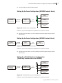
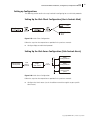
Setting Up the Jupiter Client Configuration (Harris Controls
Jupiter)
Harris
remote control
panel
Panacea
router
X-Y
protocol
Edge:
Jupiter client
Jupiter
protocol
Jupiter
router
Figure 5-25 Jupiter Client Configuration
Follow the steps for these operations as provided in the pertinent manuals:
Configure Edge to enable Jupiter protocol.
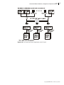
Setting Up the Jupiter Server Configuration (Jupiter Controls
Harris)
Harris
routing switcher
Jupiter
routing system
Jupiter
protocol
Edge:
Jupiter server
X-Y
protocol
Harris
routing switcher
Harris
remote control
panel
Figure 5-26 Jupiter Server Configuration
Follow the steps for these operations as provided in the pertinent manuals:
Configure the Harris router (see the installation manual that applies to your specific
Harris router).
Configuring for Use with Jupiter Client or Server Protocol
Note: Settings for Edge DIP switches are shown in Figure 3-14 on page 20
DIP Switch Mode (Configuring via DIP Switches)
The following DIP switches must be set to configure Edge for use with Jupiter client or
server protocol.
Copyright © 2005-2011, Harris Corporation
Edge
Frame and Firmware Installation, Configuration, and Operation Manual
Make sure that pole 1 of SW1 is set to OFF.
Set up the protocol you want to run (pole 6 of SW3).
Set up the appropriate baud rate (poles 7-8 of SW3).
Set up the appropriate mode; usually RS-422 for Jupiter (pole 1 of SW3).
If the Jupiter router is an end point, the Termination DIP switch (pole 2 of SW3) must be
ON.
37
Program Mode (Configuration via RouterMapper)
Configuring in Program mode is performed through the Navigator or RouterMapper
configuration utility software. To perform this operation:
Your Edge must be configured with a valid IP address and configured to allow FTP client
connections. See Network Configuration from Terminal Control Mode on page 74
for additional information on how to configure IP settings.
You must have a PC (with configuration utility application software installed) attached
to the Harris router. Make sure that the router is configured as described in the
installation manual that applies to your specific router.
You must create, or have an existing, Navigator or RouterMapper database. For more
detailed information, see the appropriate configuration utility reference guide.
To configure Edge for use with Jupiter server protocol in Program mode1, follow these
steps.
1
Make sure that pole 1 of SW1 is set to ON.
2
Make sure that pole 6 of SW3 is set to ON.
3
Start up your configuration utility software; make sure that the appropriate
communications settings are selected.
4
Poll the system.
If no errors are encountered, the Device List is updated.
If errors are encountered, error messages are returned. Refer to the appropriate
configuration utility reference guide for information on how to correct returned
errors.
5
Double-click on the desired Edge configuration listed in the Device List.
6
At the Edit Edge dialog box, select the Serial Protocols tab.
7
Double-click on the target serial port to which the Jupiter router is attached.
The Options window appears. Assigned values for the default protocol’s baud rate,
parity, data bits, stop bits, and serial interface are displayed.
a
Select the desired Jupiter protocol from the Protocol drop-down list.
The assigned values for the selected protocol appear. While all relevant protocol
option values are displayed, some values may not be configurable. These values are
displayed for informational purposes only; you cannot change them through your
configuration utility software.
b
Select the desired baud rate by highlighting the baud rate value only.
A drop-down menu appears, which allows you to change the selection.
c
Select the desired mode by highlighting the serial interface value only.
A drop-down menu appears, which allows you to change the selection (usually
RS-422 for Jupiter).
d
1
Select the desired termination by highlighting the termination status value only.
Navigator v. 4.5 and RouterMapper v. 6.00 or higher support Jupiter configuration.
Copyright © 2005-2011, Harris Corporation
38
Chapter 5
Protocol Translation Configuration
A drop-down menu appears, which allows you to change the selection. If the
Jupiter router is at an end point, the termination status value must be set to
Terminated.
e
Click OK to return to the Edge serial ports window, and then click OK to accept the
changes.
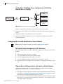
Configuring for Use with NVISION Protocols
The following information is specific to setting up your system so that you can operate it via
the Edge. Complete details on how to set up and configure your NVISION routing systems
are located in their respective operation manuals.
Setting up Configurations
The following sections outline the steps involved in configuring for use with NVISION
protocols.
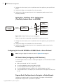
Setting Up the Client Configuration (Harris Controls NVISION)
Harris
remote control
panel
Panacea
router
X-Y
protocol
Edge:
NVISION client
NVISION
protocol
NVISION
router
Figure 5-27 NVISION Client Configuration
Follow the steps for these operations as provided in the pertinent manuals:
Configure Edge to enable NVISION protocol.
Setting Up the Client Configuration (Harris Controls NV9000)
Harris
remote control
panel
X-Y
protocol
Edge:
NV9000 client
NV9000
protocol
NV9000
master control
Panacea
router
Figure 5-28 NV9000 Client Configuration
Follow the steps for these operations as provided in the pertinent manuals:
Copyright © 2005-2011, Harris Corporation
Edge
Frame and Firmware Installation, Configuration, and Operation Manual
39
Configure Edge to enable NV9000 protocol.
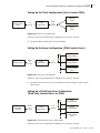
Setting Up the Server Configuration (NVISION Controls Harris)
Harris
routing switcher
NVISION
control panel
NVISION
protocol
Edge:
NVISION server
Harris
routing switcher
X-Y
protocol
Harris
remote control
panel
Figure 5-29 NVISION Server Configuration
Follow the steps for these operations as provided in the pertinent manuals:
Configure the Harris router (see the installation manual that applies to your specific
Harris router).
Setting Up the Server Configuration (NV9000 Controls Harris)
NV9000
master control
NV9000
protocol
Edge:
NV9000 server
X-Y
protocol
Harris
routing switcher
Figure 5-30 NVISION Server Configuration
Follow the steps for these operations as provided in the pertinent manuals:
Configure the Harris router (see the installation manual that applies to your specific
Harris router).
Setting Up a Third-Party Server Configuration
(Third Party Controls Harris via NVISION)
Harris
routing switcher
Harris or other
third-party
controller
NVISION
protocol
Edge:
NVISION server
X-Y
protocol
Harris
routing switcher
Harris
remote control
panel
Figure 5-31 NVISION/Third-Party Server Configuration
Follow the steps for these operations as provided in the pertinent manuals:
Copyright © 2005-2011, Harris Corporation
40
Chapter 5
Protocol Translation Configuration
1
Configure the Harris router (see the installation manual that applies to your specific Harris
router).
2
Configure the Edge server protocol to listen for connections.
3
Configure the third-party control system (see the appropriate product manual for the
third-party hardware).
Setting Up a Third-Party Server Configuration
(Third Party Controls Harris via NV9000)
Harris
routing switcher
Harris or other
third-party
controller
NV9000
protocol
Edge:
NV9000 server
X-Y
protocol
Harris
routing switcher
Harris
remote control
panel
Figure 5-32 NV9000/Third-Party Server Configuration
Follow the steps for these operations as provided in the pertinent manuals:
1
Configure the Harris router (see the installation manual that applies to your specific Harris
router).
2
Configure the Edge server protocol to listen for connections.
3
Configure the third-party control system (see the appropriate product manual for the
third-party hardware).
Configuring for Use with NVISION or NV9000 Client or Server Protocol
Note: Settings for Edge DIP switches are shown in Figure 3-14 on page 20.
DIP Switch Mode (Configuring via DIP Switches)
The following DIP switches must be set to configure Edge for use with NVISION or NV9000
server protocol.
Make sure that pole 1 of SW1 is set to OFF.
Set up the protocol you want to run (pole 6 of SW3).
Set up the appropriate baud rate (poles 7-8 of SW3).
Set up the appropriate mode; usually RS-422, for NVISION (pole 1 of SW3).
If the NVISION router is an end point, the Termination DIP switch (pole 2 of SW3) must
be ON.
Program Mode (Configuration via Navigator or RouterMapper)
Configuring in Program mode is performed through the Navigator or RouterMapper
configuration utility software. To perform this operation:
Copyright © 2005-2011, Harris Corporation
Edge
Frame and Firmware Installation, Configuration, and Operation Manual
Your Edge must be configured with a valid IP address and configured to allow FTP client
connections. See Network Configuration from Terminal Control Mode on page 74
for additional information on how to configure IP settings.
You must have a PC (with configuration utility software installed) attached to the Harris
router. Make sure that the router is configured as described in the installation manual
that applies to your specific router.
You must create, or have an existing, Navigator or RouterMapper database. For more
detailed information, see the appropriate configuration utility reference guide.
41
To configure Edge for use with NVISION or NV9000 client or server protocol in Program
mode1, follow these steps.
1
Make sure that pole 1 of SW1 and pole 6 of SW3 are set to ON.
2
Start up your configuration utility software; make sure that the appropriate
communications settings are selected.
3
Poll the system.
If no errors are encountered, the Device List is updated.
If errors are encountered, error messages are returned. Refer to the appropriate
configuration utility reference guide for information on how to correct returned
errors.
4
Double-click on the desired Edge configuration listed in the Device List.
5
At the Edit Edge dialog box, select the Serial Protocols tab.
6
Double-click on the target serial port to which the NVISION router is attached.
The Options window appears. Assigned values for the default protocol’s baud rate,
parity, data bits, stop bits, and serial interface are displayed.
a
Select the desired NVISION protocol from the Protocol drop-down list.
The assigned values for the selected protocol appear. While all relevant protocol
option values are displayed, some values may not be configurable. These values are
displayed for informational purposes only; you cannot change them through your
configuration utility software.
b
Select the desired baud rate by highlighting the baud rate value only.
A drop-down menu appears, which allows you to change the selection.
c
Select the desired mode by highlighting the serial interface value only.
A drop-down menu appears, which allows you to change the selection (usually
RS-422 for NVISION).
d
Select the desired termination by highlighting the termination status value only.
A drop-down menu appears, which allows you to change the selection. If the
NVISION router is at an end point, the termination status value must be set to
Terminated.
e
1
Click OK to return to the Edge serial ports window, and then click OK to accept the
changes.
Navigator v. 4.5 and RouterMapper v. 5.13 or higher support NVISION and NV9000 configuration.
Copyright © 2005-2011, Harris Corporation
42
Chapter 5
Protocol Translation Configuration
Configuring for Use with PESA Protocols
Configuration Notes
The PESA protocol interprets (parses) commands and replies by counting fields based on the
number of “configured” levels. In a PESA system, both the controller and router must agree
on the number of levels, or communications is impossible. On the Edge, this information is
read from a names.txt file generated by Navigator or RouterMapper. For example, if
configuring an Edge to control a PESA routing system, the Navigator or RouterMapper
database must exactly describe the PESA router.
Another requirement is that the levels start with zero (our numbering system) and that they
be contiguous (for example, you cannot define a system that has levels 0, 1, and 5). PESA
also assumes that all routing matrices on all levels are the same size. If you must configure a
system with different size matrices, you can sidestep this requirement by assigning the
largest matrix to level zero. This protocol does not work with Source or Destination offsets.
All sources and destinations must begin with zero (our numbers).
Internally, the PESA protocol is one-based. The Edge software adds or subtracts one when
processing PESA commands. This means that our level zero corresponds to their level one,
etc.
By default, the PESA protocol terminates a command with an ASCII carriage return (CR)
followed by an ASCII line feed (LF), and expects these to be received in that order. Some
PESA routers can be configured to not require the (CR). The Edge accepts commands with
or without the (CR), but always sends (CR)(LF).
The Edge PESA Server supports all of the commands listed in the protocol document.
However, many of those commands are not supported by all PESA routers. This meant that
in order to work with all PESA routers, our Edge PESA client had to use only that subset of
commands supported by all of their routers (H, J, L, W and Y).
The PESA protocol does not support asynchronous statusing. In order to show up-to-date
status at the controller for changes made by other controllers to the router, the Client polls
for destination and lock status every two seconds. This works for small and medium sized
routers, but very large routers cannot answer the destination poll because of a 2K limit on
packet size. On very large routers, the Client can take switches and see status for changes
that it made, but changes made to the router by other controllers are not reported.
The following information is specific to setting up your system so that you can operate it via
the Edge. Complete details on how to set up and configure your PESA routing systems are
located in their respective operation manuals.
Setting up Configurations
If you haven’t already done so, review the Configuration Notes on page 42.
Copyright © 2005-2011, Harris Corporation
Edge
Frame and Firmware Installation, Configuration, and Operation Manual
43
Setting Up the Client Configuration (Harris Controls PESA)
Harris
remote control
panel
X-Y
protocol
Edge:
PESA client
PESA
P1
protocol
Panacea
router
PESA
router
Figure 5-33 PESA Client Configuration
Follow the steps for these operations as provided in the pertinent manuals:
Configure Edge to enable PESA CPU Link protocol.
Setting Up the Server Configuration (PESA Controls Harris)
Harris
routing switcher
PESA
routing system
PESA
P1
protocol
Edge:
PESA server
X-Y
protocol
Harris
routing switcher
Harris
remote control
panel
Figure 5-34 PESA Server Configuration
Follow the steps for these operations as provided in the pertinent manuals:
Configure the Harris router (see the installation manual that applies to your specific
Harris router).
Setting Up a Third-Party Server Configuration
(Third Party Controls Harris via PESA)
Harris
routing switcher
Harris or other
third-party
controller
PESA
P1
protocol
Edge:
PESA server
X-Y
protocol
Harris
routing switcher
Harris
remote control
panel
Figure 5-35 PESA/Third-Party Server Configuration
Follow the steps for these operations as provided in the pertinent manuals:
Copyright © 2005-2011, Harris Corporation
44
Chapter 5
Protocol Translation Configuration
1
Configure the Harris router (see the installation manual that applies to your specific Harris
router).
2
Configure the Edge server protocol to listen for connections.
3
Configure the third-party control system (see the appropriate product manual for the
third-party hardware).
Follow the steps for these operations as provided in the pertinent manuals:
1
Configure the Harris router (see the installation manual that applies to your specific Harris
router).
2
Configure the Edge server protocol to listen for connections.
3
Configure the third-party control system (see the appropriate product manual for the
third-party hardware).
Configuring for Use with PESA CPU Link Client or Server Protocol
If you haven’t already done so, review the Configuration Notes on page 42.
DIP Switch Mode (Configuring via DIP Switches)
Note: Settings for Edge DIP switches are shown in Figure 3-14 on page 20.
The following DIP switches must be set to configure Edge for use with PESA CPU Link server
protocol.
Make sure that pole 1 of SW1 is set to OFF.
Set up the protocol you want to run (pole 6 of SW3).
Set up the appropriate baud rate (poles 7-8 of SW3).
Set up the appropriate mode; usually RS-422, for PESA (pole 1 of SW3).
If the PESA router is an end point, the Termination DIP switch (pole 2 of SW3) must be
ON.
Program Mode (Configuration via Navigator or RouterMapper)
Configuring in Program mode is performed through the Navigator or RouterMapper
configuration utility. To perform this operation:
Your Edge must be configured with a valid IP address and configured to allow FTP client
connections. See Network Configuration from Terminal Control Mode on page 74
for additional information on how to configure IP settings.
You must have a PC (with configuration utility software installed) attached to the Harris
router. Make sure that the router is configured as described in the installation manual
that applies to your specific router.
You must create, or have an existing, Navigator or RouterMapper database. For more
detailed information, see the appropriate configuration utility reference guide.
If you haven’t already done so, review the Configuration Notes on page 42.
To configure Edge for use with PESA CPU Link client or server protocol in Program mode1,
follow these steps.
1 Navigator
Copyright © 2005-2011, Harris Corporation
v. 4.5 and RouterMapper v. 6.02 or higher support PESA CPU Link configuration.
Edge
Frame and Firmware Installation, Configuration, and Operation Manual
1
Make sure that pole 1 of SW1 is set to ON.
2
Make sure that pole 6 of SW3 is set to ON.
3
Start up your configuration utility software; make sure that the appropriate
communications settings are selected.
4
Poll the system.
If no errors are encountered, the Device List is updated.
If errors are encountered, error messages are returned. Refer to the appropriate
configuration utility reference guide for information on how to correct returned
errors.
5
Double-click on the desired Edge configuration listed in the Device List.
6
At the Edit Edge dialog box, select the Serial Protocols tab.
7
Double-click on the target serial port to which the PESA router is attached.
45
The Options window appears. Assigned values for the default protocol’s baud rate,
parity, data bits, stop bits, and serial interface are displayed.
a
Select the desired PESA protocol from the Protocol drop-down list.
The assigned values for the selected protocol appear. While all relevant protocol
option values are displayed, some values may not be configurable. These values are
displayed for informational purposes only; you cannot change them through your
configuration utility software.
b
Select the desired baud rate by highlighting the baud rate value only. A drop-down
menu appears, which allows you to change the selection.
c
Select the desired mode by highlighting the serial interface value only.
A drop-down menu appears, which allows you to change the selection (usually
RS-232 for PESA).
d
If using RS-422, select the desired termination by highlighting the termination status
value only.
A drop-down menu appears, which allows you to change the selection. If the PESA
router is at an end point, the termination status value must be set to Terminated.
e
Click OK to return to the Edge serial ports window, and then click OK to accept the
changes.
Configuring for Use with Pro-Bel Protocols
The following information is specific to setting up your system so that you can operate it via
Edge. Complete details on how to set up and configure your Pro-Bel routing systems are
located in their respective operation manuals.
Setting Up Configurations
The following sections outline the steps involved in configuring for use with Pro-Bel
protocols.
Copyright © 2005-2011, Harris Corporation
46
Chapter 5
Protocol Translation Configuration
Setting Up the Pro-Bel Client Configuration (Harris Controls
Pro-Bel)
Harris
remote control
panel
X-Y
protocol
Edge:
Pro-Bel client
Pro-Bel
protocol
Panacea
router
Pro-Bel
router
Figure 5-36 Pro-Bel Client Configuration
Follow the steps for these operations as provided in the pertinent manuals:
Configure Edge to enable Pro-Bel protocol.
Setting Up the Pro-Bel Server Configuration (Pro-Bel Controls
Harris)
Harris
routing switcher
Pro-Bel
routing system
Pro-Bel
protocol
Edge:
Pro-Bel server
X-Y
protocol
Harris
routing switcher
Harris
remote control
panel
Figure 5-37 Pro-Bel Server Configuration
Follow the steps for these operations as provided in the pertinent manuals:
Configure the Harris router (see the installation manual that applies to your specific
Harris router).
Copyright © 2005-2011, Harris Corporation
Edge
Frame and Firmware Installation, Configuration, and Operation Manual
47
Setting Up a Third-Party Server Configuration (Third Party
Controls Harris via Pro-Bel)
Harris
routing switcher
Pro-Bel
protocol
Harris or
other third party
controller
Edge:
Pro-Bel server
X-Y
protocol
Harris
routing switcher
Harris
remote control
panel
Figure 5-38 Third-Party Server Configuration
Follow the steps for these operations as provided in the pertinent manuals:
1
Configure the Harris router (see the installation manual that applies to your specific Harris
router).
2
Configure the Edge server protocol to listen for connections.
3
Configure the third-party control system (see the appropriate product manual for the
third-party hardware).
Configuring for Use with Pro-Bel Client or Server Protocol
Note: Settings for Edge DIP switches are shown in Figure 3-14 on page 20.
DIP Switch Mode (Configuring via DIP Switches)
The following DIP switches must be set to configure Edge for use with Pro-Bel client or
server protocol.
Make sure that pole 1 of SW1 is set to OFF.
Set up the protocol you want to run (pole 6 of SW3).
Set up the appropriate baud rate (poles 7-8 of SW3).
Set up the appropriate mode; usually RS-422 for Pro-Bel (pole 1 of SW3).
If the Pro-Bel router is an end point, the Termination DIP switch (pole 2 of SW3) must be
ON.
Program Mode (Configuration via Navigator or RouterMapper)
Configuring in Program mode is performed through the Navigator or RouterMapper
configuration utility. To perform this operation:
Your Edge must be configured with a valid IP address and configured to allow FTP client
connections. See Network Configuration from Terminal Control Mode on page 74
for additional information on how to configure IP settings.
You must have a PC (with configuration utility application software installed) attached
to the Harris router. Make sure that the router is configured as described in the
installation manual that applies to your specific router.
Copyright © 2005-2011, Harris Corporation
48
Chapter 5
Protocol Translation Configuration
You must create, or have an existing, Navigator or RouterMapper database. For more
detailed information, see the appropriate configuration utility reference guide.
To configure Edge for use with Pro-Bel client or server protocol in Program mode1, follow
these steps.
1
Make sure that pole 1 of SW1 is set to ON.
2
Make sure that pole 6 of SW3 is set to ON.
3
Start up your configuration utility software; make sure that the appropriate
communications settings are selected.
4
Poll the system.
If no errors are encountered, the Device List is updated.
If errors are encountered, error messages are returned. Refer to the appropriate
configuration utility reference guide for information on how to correct returned
errors.
5
Double-click on the desired Edge configuration listed in the Device List.
6
At the Edit Edge dialog box, select the Serial Protocols tab.
7
Double-click on the target serial port to which the Pro-Bel router is attached.
The Options window appears. Assigned values for the default protocol’s baud rate,
parity, data bits, stop bits, and serial interface are displayed.
a
Select the desired Pro-Bel protocol from the Protocol drop-down list.
The assigned values for the selected protocol appear. While all relevant protocol
option values are displayed, some values may not be configurable. These values are
displayed for informational purposes only; you cannot change them through your
configuration utility software.
b
Select the desired baud rate by highlighting the baud rate value only.
A drop-down menu appears, which allows you to change the selection.
c
Select the desired mode by highlighting the serial interface value only.
A drop-down menu appears, which allows you to change the selection (usually
RS-422 for Pro-Bel).
d
Select the desired termination by highlighting the termination status value only.
A drop-down menu appears, which allows you to change the selection. If the
Pro-Bel router is at an end point, the termination status value must be set to
Terminated.
e
Click Mappings... to set up levels, inputs, outputs, and matrices for the Pro-Bel routing
system.
f
Click OK to return to the Edge serial ports window, and then click OK to accept the
changes.
Configuring for Use with Utah Protocols
The following information is specific to setting up your system so that you can operate it via
Edge. Complete details on how to set up and configure your Utah Scientific routing systems
are located in their respective operation manuals.
1 Navigator
Copyright © 2005-2011, Harris Corporation
v. 4.5 and RouterMapper v. 6.01 or higher support Pro-Bel configuration.
Edge
Frame and Firmware Installation, Configuration, and Operation Manual
49
Setting up Configurations
The following sections outline the steps involved in configuring for use with Utah protocols.
Setting Up the Utah Client Configuration (Harris Controls Utah)
Figure 5-39 Utah Client Configuration
Follow the steps for these operations as provided in the pertinent manuals:
Configure Edge to enable Utah protocol.
Setting Up the Utah Server Configuration (Utah Controls Harris)
Harris
routing switcher
Utah Scientific
control panel
Utah
RCP-1
protocol
Edge:
Utah server
X-Y
protocol
Harris
routing switcher
Harris
remote control
panel
Figure 5-40 Utah Server Configuration
Follow the steps for these operations as provided in the pertinent manuals:
Configure the Harris router (see the installation manual that applies to your specific
Harris router).
Copyright © 2005-2011, Harris Corporation
50
Chapter 5
Protocol Translation Configuration
Setting Up a Third-Party Server Configuration (Third Party
Controls Harris via Utah)
Harris
routing switcher
Utah
RCP-1
protocol
Harris or
other third party
controller
Edge:
Utah server
X-Y
protocol
Harris
routing switcher
Harris
remote control
panel
Figure 5-41 Third-Party Server Configuration
Follow the steps for these operations as provided in the pertinent manuals:
1
Configure the Harris router (see the installation manual that applies to your specific Harris
router).
2
Configure the Edge server protocol to listen for connections.
3
Configure the third-party control system (see the appropriate product manual for the
third-party hardware).
Configuring for Use with Utah Client or Server Protocol
Note: Settings for Edge DIP switches are shown in Figure 3-14 on page 20.
DIP Switch Mode (Configuring via DIP Switches)
The following DIP switches must be set to configure Edge for use with Utah client or server
protocol.
Make sure that pole 1 of SW1 is set to OFF.
Set up the protocol you want to run (pole 6 of SW3).
Set up the appropriate baud rate (poles 7-8 of SW3).
Set up the appropriate mode; usually RS-422 for Utah (pole 1 of SW3).
If the Utah router is an end point, the Termination DIP switch (pole 2 of SW3) must be
ON.
Program Mode (Configuration via Navigator or RouterMapper)
Configuring in Program mode is performed through the Navigator or RouterMapper
configuration utility software. To perform this operation:
Your Edge must be configured with a valid IP address and configured to allow FTP client
connections. See Network Configuration from Terminal Control Mode on page 74
for additional information on how to configure IP settings.
You must have a PC (with configuration utility software installed) attached to the Harris
router. Make sure that the router is configured as described in the installation manual
that applies to your specific router.
Copyright © 2005-2011, Harris Corporation
Edge
Frame and Firmware Installation, Configuration, and Operation Manual
51
You must create, or have an existing, Navigator or RouterMapper database. For more
detailed information, see the appropriate configuration utility reference guide.
To configure Edge for use with Utah client or server protocol in Program mode1, follow
these steps.
1
Make sure that pole 1 of SW1 is set to ON.
2
Make sure that pole 6 of SW3 is set to ON.
3
Start up your configuration utility software; make sure that the appropriate
communications settings are selected.
4
Poll the system.
If no errors are encountered, the Device List is updated.
If errors are encountered, error messages are returned. Refer to the appropriate
configuration utility reference guide for information on how to correct returned
errors.
5
Double-click on the desired Edge configuration listed in the Device List.
6
At the Edit Edge dialog box, select the Serial Protocols tab.
7
Double-click on the target serial port to which the Utah router is attached.
The Options window appears. Assigned values for the default protocol’s baud rate,
parity, data bits, stop bits, and serial interface are displayed.
a
Select the desired Utah protocol from the Protocol drop-down list.
The assigned values for the selected protocol appear. While all relevant protocol
option values are displayed, some values may not be configurable. These values are
displayed for informational purposes only; you cannot change them through your
configuration utility software.
b
Select the desired baud rate by highlighting the baud rate value only.
A drop-down menu appears, which allows you to change the selection.
c
Select the desired mode by highlighting the serial interface value only.
A drop-down menu appears, which allows you to change the selection (usually
RS-422 for Utah).
d
Select the desired termination by highlighting the termination status value only.
A drop-down menu appears, which allows you to change the selection. If the Utah
router is at an end point, the termination status value must be set to Terminated.
e
Click OK to return to the Edge serial ports window, and then click OK to accept the
changes.
Configuring for Name Support
The name support capability is important for use with protocols that use names (rather than
numeric indices) in commands to identify router levels, sources, and destinations. See
Chapter 7, Supporting Level, Source, or Destination Names With Edge for more
detailed information about names and name support for Edge products.
Configuring for name support is performed through the Navigator or RouterMapper
configuration utility. To perform this operation:
1
Your Edge must be configured with a valid IP address and configured to allow FTP
client connections. See Network Configuration from Terminal Control Mode
on page 74 for additional information on how to configure IP settings.
Navigator v. 4.5 and RouterMapper v. 5.13 or higher support Utah configuration.
Copyright © 2005-2011, Harris Corporation
52
Chapter 5
Protocol Translation Configuration
You must have a PC (with configuration utility software configuration utility
application software installed) attached to the Harris router.
Note: Instructions for specific protocols indicate if these steps are required.
1
Configure the Harris router and router system. For more detailed information, see the
installation manual that applies to your specific router.
2
Create a Navigator or RouterMapper database. For more detailed information, see the
appropriate configuration utility reference guide.
3
Add the appropriate Edge configuration to the database.
4
If necessary, assign the desired names using Navigator or RouterMapper. Save the database.
Configuration Examples
Harris router control software applications and remote control panels (hardware) use
the Edge to command and monitor routing switcher systems. Figure 5-42 shows an
example of Ethernet connectivity for Edge configuration applications. When using
Navigator or a remote control panel, configure the routing system as shown in Figure 5-42.
Figure 5-42 An Example of Ethernet Connectivity for PC-Based Configuration/Control
Applications
Copyright © 2005-2011, Harris Corporation
Edge
Frame and Firmware Installation, Configuration, and Operation Manual
53
Figure 5-43 Remote Applications for RouterMapper/RouterWorks
X-Y protocol is a Harris legacy protocol used to command and monitor router switching
systems. This protocol can be transported via Ethernet, serial, or LXY coax media (or a
mixture of those three types) throughout the network. Figure 5-44 shows an example of
remote applications for newer Ethernet-based control panels. Figure 5-45 on page 55
shows an example of remote applications for RCP panels.
Copyright © 2005-2011, Harris Corporation
54
Chapter 5
Protocol Translation Configuration
Figure 5-44 Remote Applications for Newer Ethernet-Based Control Panels
Copyright © 2005-2011, Harris Corporation
Edge
Frame and Firmware Installation, Configuration, and Operation Manual
55
Figure 5-45 An Example of Remote Applications for RCP Panels
Copyright © 2005-2011, Harris Corporation
56
Chapter 5
Protocol Translation Configuration
Copyright © 2005-2011, Harris Corporation
57
6
Protocol Formats and Terminal
Operations
This section contains information concerning various protocol formats and their operation as
they apply to the Edge. It does not contain detailed background information concerning
these protocols.
The Harris Serial Protocol Reference Manual contains detailed information concerning
terminal protocol and X-Y commands.
The Grass Valley Routing Products Protocols Manual and Grass Valley Group Series 7000
Signal Management System Configuration Manual contain detailed information
concerning the GVG SMS-7000 protocol.
The following Jupiter documents contain detailed information concerning the Jupiter
protocol:
ESswitch Serial Routing Switcher Control Protocol Guide (04-045707-008)
Jupiter Getting Started Guide (04 045707 003)
The following NVISION documents contain detailed information concerning the
NVISION protocol:
NVISION Ethernet Protocol, Router Control Messages (NP0016-00), Rev.B
NVISION Serial Protocol, Router Control Messages (NP0010-02), Rev.B
The PESA CPU Link Protocol No. 1 (P1) manual contains detailed information concerning
the PESA P1 protocol.
The Pro-Bel Router Control Protocols (SW-P-88, Issue No. 2) manual contain detailed
information concerning the SW-P-02 and SW-P-08 protocols.
The Utah Scientific Routing Switcher Controls Protocol manual contains detailed
information concerning the RCP-1 and Utah-12 protocols.
Protocol Formats
Using Harris Terminal Protocol
Terminal protocol is implemented via one of the Edge serial ports. Terminal protocol is useful
as an interface to a router to check the status of the router, to change the crosspoints, and
to write and execute simple automated programs.
DIP Switch Settings
There are no special DIP switch settings necessary to run terminal protocol.
Copyright © 2005-2011, Harris Corporation
58
Chapter 6
Protocol Formats and Terminal Operations
System Operations and Queries
Commands in the systems operations and queries group are used to set the Echo Mode, list
the current crosspoint connection status, obtain command syntax information, and
determine the system configuration. System operations and queries are performed by
executing the QUERY, INFORMATION, READ, POLL, ZERO, and TERMINAL commands.
In addition, the Edge supports DESTINATION, LEVEL, SOURCE, SHOW MENU [X],
XPOINT, and REBOOT commands.
You can find a description each of these commands in Table 6-23 on page 77. Please refer
to the Serial Protocol Reference Manual for a detailed explanation of these commands.
Using Pass-Through Protocol (X-Y Commands)
Pass-through protocol is a simple protocol suited to automated/programmed control of a
Harris router system. If you want a simple way to make a switch from a dumb ASCII
terminal with no computer or automated control/status required, the terminal protocol is
probably a better choice. For debugging and any computer or automated control and/or
monitoring, the pass-through protocol is a much better solution.
Supported Commands
Table 6-7 X-Y Commands Supported
Command Name
Syntax
Response
Action
Buffer clear
B:C
None
Buffers are cleared only if
any routing hardware is
present
Buffer execute
B:E
S:
Buffers are taken only if
any routing hardware is
present
Level poll size query
F?
F: only if any routing
hardware is present
None
Level poll size reply
F:
None
The size of the largest
frame on each level is
updated in the internal
system status table; this is
used to determine how
many GVG destinations
and sources to status
Device discovery query
I?
I!
None
Device discovery reply
I!
None
None; the server does not
monitor replies from other
devices
Buffer crosspoint preset P:
None
Buffers are preset only if
any routing hardware is
present
Alarm status query
Q! (power supply alarms
only on Edge)
None
Q?
Copyright © 2005-2011, Harris Corporation
Edge
Frame and Firmware Installation, Configuration, and Operation Manual
59
Table 6-7 X-Y Commands Supported (Continued)
Command Name
Syntax
Response
Action
Alarm status reply
Q:
None
None; the server does not
monitor alarms from other
devices
Extended alarm
reporting
Q!
None
None; the server does not
monitor alarms from other
devices
Level status query
S?
S: only if any routing
hardware is present
None
Crosspoint status reply
S:
None
Crosspoint status is
updated in the internal
system status table; this
data is used to generate
the status replies for the
GVG destination query
command series and for
the R[ead] terminal
command
Crosspoint restrict
query
U?
U! only if any routing
hardware is present
None
Crosspoint restrict set/
clear
U:
U! only if any routing
hardware is present
Crosspoints are blocked if
any routing hardware is
present
Crosspoint restrict
status
U!
None
None
Buffer preset status
query
V?
V: only if any routing
hardware is present
None
Buffer preset status
reply
V:
None
None
Lock/Protect status
query
W?
W! for local routing
hardware
None
Lock/Protect status
reply
W!
None
Lock information is
updated in the internal
system status table; this
data is used to generate
the <N|P> field for the
GVG destination query
command series
Lock/Protect status set
W:
W! for local routing
hardware
Lock/protect/unlock local
routing hardware
Crosspoint status query
X?
S: only if any routing
hardware is present
None
Crosspoint Take request X:
S: only if any routing
hardware is present
Crosspoints are taken if
any routing hardware is
present
Copyright © 2005-2011, Harris Corporation
60
Chapter 6
Protocol Formats and Terminal Operations
Using GVG SMS-7000 Protocol
Table 6-8 provides a brief listing of the GVG SMS-7000 commands available through Edge.
Table 6-9 on page 62 lists unsupported commands. Please refer to the Grass Valley Routing
Products Protocols Manual for a detailed explanation of the Series 7000 native protocol.
DIP Switch Settings
If you are using a protocol other than Harris terminal protocol, the SW3 pole 6 DIP switch
on your Edge must be set to ON.
Supported Commands
Table 6-8 GVG SMS-7000 Native Commands Supported
Command
Syntax
Description
Background Activities
Used without
parameters to
synchronize
communications
Client/Server
Server
Return system name
BK,N
Return protocol
processor software
revision
BK,R
Return native protocol
software title
BK,t
Return status bit flags
BK,F
Server
Clear status bit flags
BK,f
Server
Force next QD
command to return
status of all
destinations
BK,D
Server
Clear flags associated
with QA,no_parameter
command
BK,A
Server
Set/query refresh
interval in seconds
BK,I
Server
Set/query level 4 echo
status
BK,E
Server
Null command
BK,2
Server
Used to periodically
refresh Protects
Used as a diagnostic
tool
Server
Server
Server
(implemented in Level
2)
Request protect
PR,dest_name,level_bitmap
Protects a specific
destination from having its
source changed
Server
Query combined
destination status
QC[,dest_name]
Returns source status on
combined levels of a
destination
Server
Query destination status
QD[,dest_name]
Qd[,dest_name]
Checks sources assigned
to destinations by
destination name
Server
Copyright © 2005-2011, Harris Corporation
Edge
Frame and Firmware Installation, Configuration, and Operation Manual
61
Table 6-8 GVG SMS-7000 Native Commands Supported (Continued)
Command
Syntax
Description
Client/Server
Query error definition
QE,error_code
Retrieves text describing a
particular error code
Server
Query destination status
by index (response type 1)
QI,destIndex,lvlIndex
Qi,destIndex,lvlIndex
Checks sources assigned
to destinations by specific
Destination and Level
Index
Server
Query destination status
by index (response type 2)
QJ[,destIndex]
Qj[,destIndex]
Checks sources assigned
to destinations by
Destination Index for all
levels
Server
Query destination status
with tieline info
QL[,dest_name]
Ql[,dest_name]
Server
Checks sources assigned
to destinations by
destination name; includes
tie line information
Query Names
Server
QN,S
Checks names associated
with sources
Server
QN,D
Checks names associated
with destinations
Server
QN,L
Checks names associated
with levels
Server
QN,V
Checks names associated
with salvos
Server
QN,IS
Checks names associated
with sources via the
Source Index
Server
QN,ID
Checks names associated
with destinations via the
Destinations Index
Server
Query date and time
QT
Checks system date and
time information
Server
Query salvo status
QV,salvo_name
Checks sources,
destinations, and levels
associated with a specified
Salvo (timed salvo
information is not
available).
Server
Request set date and time
ST,yyymmddhhmmss
Request Take
TA,dest_name,nbr_sources,src_name_
entry1[,...src_name_entryn]
Takes Sources (on
specified levels) to
specified destination, by
name rather than index
Server
Request Take destination
TD,dest_name,src_name_entry
Takes same source to all
or specified levels
Server
Query source names
Query destination
names
Query level names
Query salvo names
Query sources with
source index
Query destinations with
destination index
Server
Copyright © 2005-2011, Harris Corporation
62
Chapter 6
Protocol Formats and Terminal Operations
Table 6-8 GVG SMS-7000 Native Commands Supported (Continued)
Command
Syntax
Description
Client/Server
Request Take by index
with level index (indexes
are zero based)
TI,destIndex,srcIndex[,levelIndex]
Takes source (on specified
level) to specified
destination by index rather
than name
Server
Request Take index with
level bitmap
TJ,destIndex,nbr_sources,srcIndex,level_bi Takes sources (on
tmap[,...,srcIndex,level_bitmap]
specified levels) to
specified destination by
index rather than name;
allows breakaways
Server
Request Take salvo
TS,salvo_name
Executes a specified salvo
Server
Request unprotect
UP,dest_name,level_bitmap
Removes Protect from
specified destination
Server
Unsupported Commands
These commands are not supported, but do return a Level 4 Error code 5, “Not
Implemented”:
Table 6-9 GVG SMS-7000 Native Commands Not Supported
Command
Syntax
Machine Assign
AS,dest_name,src_name
Background Activities
Return smsApp software title
BK,T
Return port configuration
parameters fixed by GUI
BK,P
Request Chop
CH,dest_name,nbr_sources,src_name_entry1,[...,src_name_entryn]
Request Clear Destination Tielines
CT,dest_name
Machine De-Assign
DA,dest_name,src_name
Query Machine Assignment Status
QA[,dest_name]
Query Names
QN,R
QN,T
QN,M
QN,Y
Request Take Monitor Destination
TM,dest_name
Using Jupiter Protocol
DIP Switch Settings
If you are using a protocol other than Harris terminal protocol, the SW3 pole 6 DIP switch
on your Edge must be set to ON.
Copyright © 2005-2011, Harris Corporation
Edge
Frame and Firmware Installation, Configuration, and Operation Manual
63
Supported Commands
Jupiter ASCII Commands
Table 6-10 identifies the Jupiter ASCII commands available through Edge. Please refer to
the appropriate Jupiter manual for a detailed explanation of these protocols.
Table 6-10 Jupiter ASCII Commands
Command
Description
Function
ZA
Acknowledge
Used to see if the ASCII interface exists and is running; a response
of ZA is returned whenever a ZA is received
ZJOOO
Report Lock Status
Returns a code based on which kind of system control device or
interface locked or protected the specified output; if the output is
not locked or protected, no response will be sent
ZN
Command Rejected
(NAK)
Issued when a condition occurs where the current command
cannot be executed
A ZN response can be issued for several reasons such as an invalid
command, an invalid command format, or an invalid input, output
or level. Invalid inputs, outputs and levels are logged to the system
logger. Also if the system is busy a ZN will be issued followed by
XOFF. When it is again ready for the next command a XON will be
issued. Note that after the XON, response(s) from the prior
command may be issued (for example, ZR response[s]).
ZPOOO
Lock Output
Locks the specified output from being changed by any system
control device
ZROOO
Status Request
Requests current switcher status for a single output
Response is in the format: ZROOOIIILLLLLLL; if the status for the
output is “split,” multiple responses will be returned
ZSOOOIIILLLLLLL
Switch Request
Causes the interface to issue a Take switch request to the routing
switcher control system and affects a single routing switcher
output; if no levels are specified, then all defined levels are
assumed.
Note: Passwords are not honored by automation protocol
handling. A remote computer can send a command with
multiple Switch Requests (older releases do not have this
capability). A single command can be up to 180 characters long
which allows switching of from 12-22 outputs (depending on the
specified levels).
ZUOOO
Unlock Output
Removes the lock or protect from the specified system output; if
another system control device or interface locked or protected this
output, this command will fail
ZVOOO
Protect Output
Protects the specified output from being changed by any other
system control device
Copyright © 2005-2011, Harris Corporation
64
Chapter 6
Protocol Formats and Terminal Operations
Table 6-10 Jupiter ASCII Commands (Continued)
Command
Description
Function
ZWOOO
Watch Output
Causes the interface to watch the specified output for any changes
and report such changes
A request to watch output “999” is a request to watch all defined
outputs in that port’s serial output set. All responses are in the “ZR”
format described above. When issued, this command also may
result in an immediate ZR response for the requested output(s). No
ZR response(s) will be returned if the requested output(s) do not
have any inputs assigned to them.
ZY
Command Accepted Returns after the serial port has successfully parsed the command
(ACK)
and, in the case of a switch command, has successfully issued the
TAKE to the system and received a switch response back from the
system.
Note: This does not mean that the command was
successfully executed. The remote computer should not
issue a new command until receiving a ZY or ZN from the
current command. The amount of time for the response will vary
depending on system complexity and current system activity. Also
the number of switches involved in the command will affect the
amount of time it takes to receive the ZY response. Multiple
switches sent in one command may result in ZR response(s) being
returned before the ZY response.
ZZ
Reset
Forces the ASCII controller to reset, which causes the interface to
cancel all previous ZP, ZV, and ZW commands
A ZX response is returned to the external computer upon command
completion. This ZX is also returned whenever the interface is
manually reset.
Jupiter ESswitch Commands
Table 6-11 and Table 6-12 identify the Jupiter ESswitch commands available through Edge.
Please refer to the Jupiter Facility Control System ESswitch Serial Routing Switcher Control
Protocol Guide for a detailed explanation of these protocols.
Table 6-11 Jupiter ESswitch Message Keywords
Hex
Message Keyword
Function
Mnemonic
22
READ
Directs the virtual machine to transmit the
instantaneous content of the specified
information field
READ
23
I/F ITEM RESPONSE
Response to READ, UPDATE, or CYCLE
commands
IFRE
4B
CLEAR CROSSPNT EXCLUSION
CCEX
Causes connection of the crosspoint between a
specified source (row or input) and specified
destination (column or output) in the specified
level of the specified matrix to be allowed;
previously connected crosspoints are not affected
42
CONNECT CROSSPOINT
Causes the crosspoint between a specified source
(row or input) and a specified destination
(column or output) in the specified level of a
specified matrix to be connected
Copyright © 2005-2011, Harris Corporation
CONC
Edge
Frame and Firmware Installation, Configuration, and Operation Manual
65
Table 6-11 Jupiter ESswitch Message Keywords (Continued)
Hex
Message Keyword
Function
Mnemonic
7E
CONNECT W/AUDIO MODE
Causes the crosspoint between a specified source
(row or input) and a specified destination
(column or output) of the specified left and right
audio levels of the specified left and right audio
matrices to be connected with the specified
audio mode
CWAM
44
LOCK CROSSPOINT
Causes a previously connected crosspoint
between a specified destination (column or
output) and its existing source (row or input) in
the specified level of the specified matrix to be
locked in its current state
LCKC
60
PRESET
Presets the named information field to a given
value
PRST
4A
SET CROSSPOINT EXCLUSION
Causes connection of the crosspoint between a
specified source (row or input) and specified
destination (column or output) in the specified
level of a specified matrix to be disallowed;
previously connected crosspoints that become
excluded are not affected
SCEX
46
SPECIFIC MUTE
Directs the controlled virtual machine to switch
off all responses previously initiated by a CYCLE
or UPDATE command for the specified
information field
SPMT
40
START-UP RESPONSE
Indicates that the controlled device has been
powered up
STUR
45
UNLOCK CROSSPOINT
Causes the crosspoint between the specified
destination (column or output) and its existing
source (row or input) in the specified level of the
specified matrix to be unlocked and available for
a change in state
UNLC
Table 6-12 Jupiter ESswitch Information Fields
Hex
Information Field Name
Function
Mnemonic
40
COMMAND ERROR STATUS
Tallies faults in the system and their reasons
detected by internal diagnostics (as applicable);
contains the returned status of failed switches
CEST
48
CROSSPOINT STATUS
Gives a list of the unconfirmed crosspoints
CSTA
corresponding to a specified destination
(column) in a specified level of a specified matrix
4F
DESTINATION NAME
Contains the name of the specified destination
in the specified level of a specified matrix
DNAM
44
DESTINATION POINTER
Defines a pointer to a destination (column or
output) in the level (specified in the LEVEL
POINTER information field) of the matrix
(specified in the MATRIX POINTER information
field)
DPOI
Copyright © 2005-2011, Harris Corporation
66
Chapter 6
Protocol Formats and Terminal Operations
Table 6-12 Jupiter ESswitch Information Fields (Continued)
Hex
Information Field Name
Function
Mnemonic
53
EXCLUSION SOURCE-TO-DEST
Indicates all sources (rows or inputs) in a
specified level of a specified matrix that cannot
be connected to a specified destination (column
or output)
EXSD
4A
LEVEL CONFIGURATION
Describes the start-up configuration in the
specified level of the specified matrix by first
defining the rectangular limits of the level and
then detailing crosspoint blocks (typically
card-related) that do not exist
LECO
42
LEVEL POINTER
Defines a pointer to a level of the matrix
specified in the MATRIX POINTER information
field
LPOI
50
LOCKED SOURCE-TO-DEST
Indicates all sources (rows or inputs) in a specific
level of a specific matrix whose crosspoint to a
destination (column or output) is locked
LSTD
41
MATRIX POINTER
Defines a pointer to a matrix
MPOI
4E
SOURCE NAME
Contains the name of the specified source in the
specified level of a specified matrix
SNAM
43
SOURCE POINTER
Defines a pointer to a source (row or input) in
the level (specified in the LEVEL POINTER
information field) of the matrix (specified in the
MATRIX POINTER information field)
SPOI
47
SOURCES-TO-DEST
Indicates all sources (rows or inputs) in a
specified level of a specified matrix that are
currently connected to a specified destination
(column or output)
STOD
Using NVISION Protocol
DIP Switch Settings
If you are using a protocol other than Harris terminal protocol, the SW3 pole 6 DIP switch
on your Edge must be set to ON.
Supported Commands
Note: NP0020 commands are not supported.
Copyright © 2005-2011, Harris Corporation
Edge
Frame and Firmware Installation, Configuration, and Operation Manual
67
Table 6-13 through Table 6-16 identify the NVISION commands available through Edge.
Please refer to the appropriate NVISION manual for a detailed explanation of these
protocols.
Table 6-13 NP0010 Command Codes
Hex Designator
Command Protocol/Comments
0x10
Manufacturer and product ID
0x11
Software version
0x50
Take (without time stamp)
0x51
Destination status
0x55
Lock destination
0x56
Protect destination
0x58
Release destination
0x59
Level configuration
0x5D
Tally request
0x5E
Salvo
0x68
Expanded tally
0x80
Error response
Table 6-14 NP0016 Command Codes
Hex Designator
Command Protocol/Comments
0x0000 0050
Take
0x0000 0051
Set output lock, protect, release
0x0000 0052
Get status of output
0x0000 0059
Router partition information
0x0000 005E
Salvo (tally)
Table 6-15 NP0017 Command Codes
Hex Designator
Command Protocol/Comments
0x0000 3001
Take input port to output port
0x0000 3003
Lock/protect/release port
0x0000 3005
Register for changes for port
0x0000 3007
Get physical crosspoint status
0x0000 3009
Get physical LPR (lock/protect/release)
status
0x0000 300C
Physical output changed
0x0000 3012
Get mnemonics
0x0000 3013
Find mnemonics
0x0000 3014
Get physical level dimensions
Copyright © 2005-2011, Harris Corporation
68
Chapter 6
Protocol Formats and Terminal Operations
Table 6-16 NP0025 Command Codes
Hex Designator
Command Protocol/Comments
0x22
Get NV9000 mnemonic
Using PESA Protocol
DIP Switch Settings
If you are using a protocol other than Harris terminal protocol, the SW3 pole 6 DIP switch
on your Edge must be set to ON.
Supported Commands
Table 6-17 and Table 6-18 identify the PESA commands available through Edge. Please
refer to the appropriate PESA manual for a detailed explanation of these protocols.
Table 6-17 PESA P1 Commands
ASCII
Command Protocol
Description
B
B SLV CS @
Display Salvo
C
C SLV S DST L1 L2 L3 L4 CS @
Change Salvo
D
D SLV S DST CS @
Delete Salvo
F
F SLV CS @
De-allocate Salvo Group.
H
H DST L1 L2 L3 L4 CS @
Change Switcher (Take)
J
J CS @
Switcher Status (no error info)
L
L S DST CS @
Change (Toggle) Lock Status
P
P S DST CS @
Change Protect Status
R
R CS @
Restore All Call
T
T L1 L2 L3 L4 CS @
All Call
W
W S CS @
Display Lock/Protect Status
Y
Y DST CS @
Switcher Status (one destination with error info)
Z
Z CS @
Switcher Status (entire matrix with error info)
Table 6-18 PESA P1 <--> X-Y Pass-Through Correlation
X-Y Pass-Through
Command
PESA P1 Command
Explanation/Comments
B:C
B:R
V?
V:
Not supported
Preset status, preset status request and preset buffer
clear and reset are not supported in RCP-1
E:
Not supported
Parameter Assignment/Matrix Take
E?
Not supported
Parameter Query/Matrix Status request
Copyright © 2005-2011, Harris Corporation
Edge
Frame and Firmware Installation, Configuration, and Operation Manual
69
Table 6-18 PESA P1 <--> X-Y Pass-Through Correlation (Continued)
X-Y Pass-Through
Command
PESA P1 Command
Explanation/Comments
F?
Not supported
Frame size request
G?
Not supported
Name Query
I?
I!
I?T
Not supported
Device discovery and reporting
I?
V
Not supported
Device version
K:
Not supported
Device name assignment
K?
Not supported
Device name request
P:
B:E
H
Preset and Preset execute are not supported in P1;
therefore a Take command will be issued to do both
jobs at the same time
Q?
Not supported
Alarm Status request/ Matrix status request
U?
U:
Not supported
Crosspoint restriction status/Query
W?
W:
W!
L, P, W
Lock/Protect a destination
Unlock/Unprotect a destination
X:
H
Crosspoint take request/Matrix take
X?
S?
J, Y, Z
Crosspoint or level status request/Matrix request
Using Pro-Bel Protocol
DIP Switch Settings
If you are using a protocol other than Harris terminal protocol, the SW3 pole 6 DIP switch
on your Edge must be set to ON.
Supported Commands
Table 6-19 and Table 6-20 identify the Pro-Bel commands available through Edge. Please
refer to the appropriate Pro-Bel manual for a detailed explanation of these protocols.
Table 6-19 Pro-Bel General Switcher Communication Protocol (SW-P-02) Command Codes
Decimal
Command Protocol/Comments
01
Interrogate message
02
Connect message
03
Tally message
04
Connected message
05
Connect On Go message
Copyright © 2005-2011, Harris Corporation
70
Chapter 6
Protocol Formats and Terminal Operations
Table 6-19 Pro-Bel General Switcher Communication Protocol (SW-P-02) Command Codes
06
Go message
12
Connect On Go Acknowledge message
13
Go Done Acknowledge message
Table 6-20 Pro-Bel General Remote Control Protocol
(SW-P-08) Command Codes
Decimal
Command Protocol/Comments
1
Crosspoint Interrogate message
2
Crosspoint Connect message
3
Crosspoint Tally message
4
Crosspoint Connected message
21
Crosspoint Tally Dump Request message
22
Crosspoint Tally Dump (BYTE) message
23
Crosspoint Tally Dump (WORD) message
Using Utah Scientific RCP-1/Utah-12 Protocol
DIP Switch Settings
If you are using a protocol other than Harris terminal protocol, the SW3 pole 6 DIP switch
on your Edge must be set to ON.
Supported Commands
Table 6-21 provides a brief listing of the Utah Scientific RCP-1/Utah-12 commands available
through Edge. Table 6-22 on page 71 lists correlations between the Utah commands and
X-Y commands. Please refer to the Utah Scientific Routing Switcher Controls Protocol
manual for a detailed explanation of the RCP-1/Utah-12 native protocol.
Table 6-21 Utah Scientific RCP-1/Utah-12 Command Codes
ASCII
HEX
Command Protocol/Comments
SOH
01
Matrix Take command
SOH <Lev 1-4> <Lev 5-8> <Matrix input>
<Matrix output>|<Checksum> | or |CR|
SOH <@><@>
(Utah-12)
01
Matrix Status Request (Same as Matrix Take
command where both level bytes are “@”
ESC @
1B 40
Matrix refresh report enable
Reported data = STX <Lev 1-4><Lev 5-8> <Matrix
input> <Matrix output> <Checksum> CR
ESC A
1B 41
Matrix refresh report disable
ESC B
1B 42
Matrix change report enable
Reported data = FS <Lev 1-4> <Lev 5-8> <Matrix
input> <Matrix output> <Checksum> CR
Copyright © 2005-2011, Harris Corporation
Edge
Frame and Firmware Installation, Configuration, and Operation Manual
71
Table 6-21 Utah Scientific RCP-1/Utah-12 Command Codes (Continued)
ASCII
HEX
Command Protocol/Comments
ESC C
1B 43
Matrix change report disable
ESC D
OR
ESC Q (Utah-12)
1B 44
Matrix original take report enable
Reported data = SOH<Lev 1-4> <Lev 5-8> <Matrix
input> <Matrix output><Checksum> CR
ESC E
OR
ESC R (Utah-12)
1B 45
Matrix original take report disable
ESC L
1B 4C
Matrix Status request
Reported data = STX <Lev 1-4> <Lev 5-8> <Matrix
input><Matrix output> <Checksum> CR
ESC 0
1B 4F
Current Mode and station name request
Reported data = HT <Mode 1> <Mode 2> <Space>
<Station name> <P/L status> <Checksum> CR
ESC P
1B 50
Program checksum request
Reported data = VT <Space><ROM checksum>
<Space> <Checksum> CR
ESC S (Utah-12)
1B 53
Enable XON/XOFF
ESC T (Utah-12)
1B 54
Disable XON/XOFF
ESC V
1B 56
Program version request
Reported data = BS <Version><Checksum> CR
Table 6-22 Utah Scientific RCP-1/Utah-12 <—> X-Y Pass-Through Correlation
XY- Pass-Through
Command
Utah RCP-1/
Utah-12 Command
Explanation/Comments
I? /I! / I?T
No equivalent
Device discovery & reporting
I?V
ESC V
Device version
E?
ESC L
Parameter Query/Matrix Status request
E:
SOH
Parameter Assignment/Matrix Take
G?
ESC 0
Name Query
Q?
No equivalent
Alarm Status request/ Matrix status request
W? / W: / W!
No equivalent
Lock, Protect / Unlock, Unprotect a destination
F?
No equivalent
Frame size request
P:
B:E
SOH
Preset and Preset execute are not supported in
RCP-1. Therefore a take command will be issued to
do both jobs at the same time.
B:C, B:R, V?, and V:
No equivalent
Preset status, preset status request and preset buffer
clear and reset are not supported in RCP-1
X:
SOH
Crosspoint take request/Matrix take
Copyright © 2005-2011, Harris Corporation
72
Chapter 6
Protocol Formats and Terminal Operations
Table 6-22 Utah Scientific RCP-1/Utah-12 <—> X-Y Pass-Through Correlation (Continued)
XY- Pass-Through
Command
Utah RCP-1/
Utah-12 Command
Explanation/Comments
X? / S?
ESC L (RCP-1) /
SOH <@> <@> (Utah-12)
Crosspoint or level status request/Matrix request
U? / U:
No equivalent
Crosspoint restriction status/Query
K:
No equivalent
Device name assignment
K?
No equivalent
Device name request
Terminal Operations
Two separate serial control ports are used to control Edge from an external computer or
automation system. Either serial port may be used to monitor the system configuration,
determine the current status of crosspoint connections, change crosspoint connections in
any matrix, and setup pre-programmed crosspoint takes sequences, or salvos. These (and
other) operations are assigned to the serial ports via a series of commands called “terminal
operation” commands. You can find a list of the startup commands available for the Edge
on page 77.
Establishing a Terminal Operation Session
The particular settings for your operation are selected via a series of configuration startup
commands. You can find a list of the startup commands available on page 77. In addition,
the configuration scenarios listed in Chapter 5, Protocol Translation Configuration cite
specific needed terminal commands.
Before you configure your Edge you will need to initiate a terminal operation session. You
need to determine which type of setup you will use:
For a standalone system with serial connections, see Establishing a Terminal
Operation Session for Serial Control Interface
Products on page 73.
For a standalone system with Ethernet connections, see Establishing a Telnet Session
for Ethernet Control Interface Products on page 73.
For a network system with serial connections see Establishing a Terminal Operation
Session for Serial Control Interface
Products on page 73 and Network
Configuration from Terminal Control Mode on page 74.
For a network system with Ethernet connections see Establishing a Telnet Session
for Ethernet Control Interface Products on page 73 and Network Configuration
from Terminal Control Mode on page 74.
Copyright © 2005-2011, Harris Corporation
Edge
Frame and Firmware Installation, Configuration, and Operation Manual
73
Establishing a Terminal Operation Session for Serial Control Interface
Products
1
2
Configure a host machine (such as a PC with HyperTerminal installed) for serial port
communication at a baud rate of 9600 with these settings: Data on the serial control port is
encoded as 8N1:
8
None
1
No flow-control
Ensure that the Edge DIP switch SW3 is set as follows:
1 = OFF (down position)
2 = OFF (down position)
3 = OFF (down position)
4 = OFF (down position)
5 = OFF (down position)
6 = OFF (down position)
7 = OFF (down position)
8 = OFF (down position)
3
Connect a null modem serial cable from a PC serial port to the Edge port labeled SERIAL1.
4
Connect the Edge Ethernet port to the router network.
5
Connect the Edge X-Y to the router network.
CAUTION
Make sure the X-Y network is terminated appropriately.
6
Start up both PC and terminal emulation application.
7
Apply power to the Edge box. The Command Summary screen should appear on the PC
screen.
Establishing a Telnet Session for Ethernet Control Interface Products
Follow these steps to establish a Telnet session to the Edge if the Telnet application is
resident on a PC:
1
Connect an Ethernet crossover cable between the 10Base-T connector on a PC to the
10Base-T connector on the Edge.
2
Change the IP address of your PC to a static IP address compatible with the Edge IP address.
Note: Invoking Telnet commands requires a valid username and password. The default
username is leitch and the default password is leitchadmin. You should change these
defaults to ones that are more meaningful for your organization.
3
At a DOS prompt, enter the word “telnet” and the IP address of the Edge (for example,
telnet 100.200.50.10).
4
Press <Enter>. The Telnet screen will appear.
5
Enter your login, then press <Enter>.
6
Enter your password, then press <Enter>.
7
The startup screen and the message “Type Q for menu...” will appear.
Copyright © 2005-2011, Harris Corporation
74
Chapter 6
Protocol Formats and Terminal Operations
8
Type in the letter “Q” (it will not appear on the screen), then press <Enter>. The Command
Summary screen will appear. (See page 76 for an example of the Command Summary
screen.)
Once a Telnet session is established, you will have access via the Telnet interface to the
commands listed in this section. Also see Telnet Interface on page 75 for more
information.
Network Configuration from Terminal Control Mode
The Edge is ready to process user commands whenever you see the prompt “>.” All
user-entered commands should be followed by a carriage return. The Edge comes
preconfigured with a network MAC address. However, you must configure the IP,
GATEWAY, and NETMASK parameters to have basic network control of the Edge.
The following are network configuration commands (commands are in bold). Please use
your proper network settings accordingly. The network parameters in these examples are
fictitious and should not be used. If you are not sure of the proper network addresses to
use, consult your Network System Administrator. From the terminal program, issue these
commands when a “>” (prompt) is seen below the Command Summary window:
>SET IP1=192.168.127.33
>
>SET GATEWAY1=192.168.127.1
>
>SET NETMASK1=255.255.255.128
>
>SAVE SYSCONFIG
Saving SysConfig.xml
Save complete.
>
You may review the network settings with the following terminal commands:
>show ipdisplay
Note: “Active” settings are the ones that the Edge currently uses. “Stored” settings are the
ones that will be used the next time the Edge is started up. The numbers will be different if
the IP address is changed.
Active:
Ip Address: 192.168.127.33
Gateway Address: 192.168.127.1
Netmask Address: 255.255.255.128
Mac address 00-90-F9-00-22-F3
Stored:
Ip Address: 192.168.127.33
Gateway Address: 192.168.127.1
Netmask Address: 255.255.255.128
Mac address 00-90-F9-00-22-F3
>
Copyright © 2005-2011, Harris Corporation
Edge
Frame and Firmware Installation, Configuration, and Operation Manual
75
This completes network configuration of Edge. For IP changes to take effect, the Edge
should be restarted. Type the REBOOT command at the terminal prompt:
>REBOOT
Telnet Interface
Telnet Configuration
The Telnet interface allows remote connection to the router from a standard Telnet client
program (such as those provided with the Windows operating system) over IP port 23. To
log into the Telnet interface, a user account and password is required (please refer to the
Table 6-28 on page 84 for appropriate user management commands).
The Telnet commands listed in Table 6-24 on page 79 provide control of Edge Telnet
interface (accessed by typing SHOW TELNET at the command prompt).The commands
appropriate to this configuration are
SET TMAXCONNECTIONS
SET TDISCONNECTUSER
SHOW TCONNECTIONS
SAVE SYSCONFIG
User Management
User accounts are required to be created for access to the router via the Telnet or FTP
interfaces exposed by the router.
Appropriate user management commands are listed in Table 6-28 on page 84.
Virtual (Network) X-Y Configuration
The virtual X-Y interface allows remote connection to a router from Harris Ethernet-enabled
router control hardware and software packages such as the RCP-ABA-E, RouterWorks, Pilot
3.0 or higher, and Navigator 2.0 or higher. To connect to the virtual X-Y interface, the router
should be configured as a virtual X-Y server and the router control device as a client (to
configure the product to connect to Edge as a client, see Setting Up the GVG Ethernet
Client Configuration (Harris Controls GVG) on page 32).
To configure the Edge’s virtual X-Y server, enable the Harris VXY Server protocol on the
hardware’s Ethernet port (see Configuring for Use with Ethernet Protocols on page 31).
Once the protocol server has been installed on the Ethernet port, it may be configured.
To enable the virtual X-Y server on the Edge’s Ethernet port, use the following commands:
>set ENET1 PROTOCOL2=ON
Copyright © 2005-2011, Harris Corporation
76
Chapter 6
Protocol Formats and Terminal Operations
(Changes must be saved and the frame reset to take effect.)
>save sysconfig
Saving SysConfig.xml
Save complete.
>reboot
To configure operational parameters of the server, use the virtual X-Y commands listed in
Table 6-24 on page 79 (accessed by typing SHOW VIRTUALXY at the command prompt).
The commands appropriate to this configuration are
SET VXYMAXCONNECTIONS
SET VXYDISCONNECTUSER
SHOW VXYCONNECTIONS
Terminal Commands
Some commands referenced in this section are explained in the Serial Protocol Reference
Operation and Reference Manual. This manual provides a detailed discussion of each
command and outlines how each product router uses these commands. (These commands
are not case-sensitive; that is, when you enter the desired command you may use all
lower-case, all upper-case, or a mix of lower and upper-case characters.) It also includes a
list of error messages and their corresponding definitions.
Basic Terminal Protocol Menu Screen
The Command Summary screen (Figure 6-46) should be seen on the terminal emulation
application. The Command Summary screen provides the basic command line entry syntax
for the commands available for Edge.
Figure 6-46 Command Summary Screen
Copyright © 2005-2011, Harris Corporation
Edge
Frame and Firmware Installation, Configuration, and Operation Manual
77
List of Terminal Commands
The commands listed in Table 6-23 are in order corresponding to their appearance on the
Command Summary screen (Figure 6-46 on page 76). Each command is defined, its syntax
is illustrated, its parameters are listed, and its response is provided. More detailed
explanations of these commands can be found in the Serial Protocol Reference Manual. You
can download a copy of this manual from our website.
Table 6-23 Terminal Commands from Terminal Protocol Menu Screen
Command
Syntax
Input Parameters
Result
DESTINATION
DESTINATION #[,#,...]
or
D#
#=Destination number
Completes crosspoint
operations after the level
number and the source
number have been set
INFORMATION
INFORMATION
or
I
None
Provides information on
the overall system as seen
from the connection to
the X-Y bus
LEVEL
LEVEL #
or
L#
#=Level number
Sets the level number for a
router that is connected to
an active system
POLL
POLL #
or
P#
#=Source number to be
searched; may be any
number 1 to 12
Determines which
destinations are
connected to a specific
source number
QUERY
QUERY
or
Q
None
Provides a list that includes
a basic command syntax
and brief description of
each command
READ
READ
or
R
None
Lists all crosspoints within
a frame in order by level
numbers, then by
destination numbers that
show which source is
assigned to each of the
destinations on that level
Each crosspoint
connection is represented
by a numeric pair
separated by a semicolon
and a space: the first
number is the destination
number; the second
number is the source
number that is connected
to that destination
SHOW MENU
SHOW MENU E
E = Ethernet command
options
Displays subcommands for
Ethernet command
options (see page 79 for a
list of subcommands)
Copyright © 2005-2011, Harris Corporation
78
Chapter 6
Protocol Formats and Terminal Operations
Table 6-23 Terminal Commands from Terminal Protocol Menu Screen (Continued)
Syntax
Input Parameters
Result
SHOW MENU F
F = File system command
options
Displays subcommands for
file system command
options (see page 82 for a
list of subcommands)
SHOW MENU H
H = Hardware options
command options
Displays subcommands for
hardware options (see
page 82 for a list of
subcommands)
SHOW MENU P
P = Protocol configuration
command options
Displays subcommands for
the protocol configuration
command options (see
page 83 for a list of
subcommands)
SHOW MENU U
U = User account
command options
Displays subcommands for
user account options
command options (see
page 84 for a list of
subcommands)
SOURCE
SOURCE #
or
S#
# = Source number.; can
range from 1 to the
maximum number of
sources on that level, or
“X” for disconnect
Sets the desired source
number
TERMINAL
TERMINAL [ON|OFF]
or
T[/F]
ON = Turns on Echo mode
OFF = Turns off Echo
mode
When ECHO mode is
ON, all the characters
sent are “echoed” to
the terminal
When ECHO mode is
OFF, messages sent are
not “echoed” to the
terminal
Command
XPOINT
(combines operations of
the LEVEL, SOURCE, and
DESTINATION commands
into one command; and
allows multiple crosspoint
connection requests in
one command)
XPOINT [#:]#,#[,#,...][/...]
or
X [#:]#,#[,#,...][/...]
[#L:]= Level number
[#S] = Source number
[,#D,#D,...] = Destination
number
The crosspoint is executed
(you can use a READ
command to confirm the
crosspoint connection)
ZERO
ZERO
or
Z
None
The device is restarted and
status is cleared
REBOOT
REBOOT
None
The device is restored, but
the status is not cleared
Copyright © 2005-2011, Harris Corporation
Edge
Frame and Firmware Installation, Configuration, and Operation Manual
79
SHOW MENU [#] Subcommands
The SHOW MENU [#] command lists submenus of commands specific to that particular
parameter you enter. The SHOW MENU subcommands are listed starting in Table 6-24
through Table 6-28 on page 84. Each command is defined, its syntax is illustrated, its
parameters are listed, and its response is provided.
Table 6-24 Menu E (Ethernet) Subcommands
Command
Syntax
Input Parameters
Result
SET IP
SET IPx=#.#.#.#
x = Ethernet port
number
#.#.#.# = IP address
(factory default
setting is
192.168.100.250)
Sets the router IP address
for a network connector;
this value is stored
permanently once set and
does not have to be entered
each time at power-up
Reboot the router device
for IP related changes to
take effect
SET GATEWAY
SET GATEWAYx=#.#.#.#
x = Ethernet port
number
#.#.#.# = Gateway IP
address (factory
default setting is
192.168.100.1)
Sets the network gateway
IP address; this value is
stored permanently once
set and does not have to be
entered each time at
power-up
Reboot the router device
for IP related changes to
take effect
SET NETMASK
SET NETMASKx=#.#.#.#
x = Ethernet port
number
#.#.#.# = System IP
address
Assigns IP address to a
subnet mask
SHOW IPDISPLAY
SHOW IPDISPLAY
None
Device will display active
and stored network IP
address, subnet mask, and
gateway address
SET BOOTDEFAULTS
SET BOOTDEFAULTS
None
Resets the IP address,
subnet mask, and network
gateway address to the
factory defaults; settings
take effect after you reboot
the device
The SET BOOTDEFAULTS command will completely overwrite all system parameters and will
require you to reset all parameters in your system before it will operate. Improper use of this
command may result in permanent damage to your router. Do not use this command without
first contacting Customer Service. If you have inadvertently used this command, contact
Customer Service immediately.
Copyright © 2005-2011, Harris Corporation
80
Chapter 6
Protocol Formats and Terminal Operations
Table 6-24 Menu E (Ethernet) Subcommands (Continued)
Command
Syntax
Input Parameters
Result
SET PING
SET PING #.#.#.#.
#.#.#.#. = IP address
of another device or
computer
If the device or computer is
accessible, CLIENT #.#.#.#.
IS ALIVE message will
appear
If the device or computer is
not accessible, HOST
UNREACHABLE message
will appear
SHOW TELNET
SHOW TELNET
None
Displays these Telnet
options available on your
device:
SET TMAXCONNECTIONS
SET TDCONNECTUSER
SHOW TCONNECTIONS
SET TMAXCONNECTIONS*
SET TMAXCONNECTIONS=# # = Number of
allowable concurrent
Telnet sessions
Restricts the maximum
number of concurrent
Telnet sessions to a specific
number (the maximum
number of sessions cannot
exceed 12)
SET TDISCONNECTUSER
SET TDISCONNECTUSER=#
# = Session number
Terminates the Telnet
connection to your device
(SHOW TCONNECTIONS
command will display the
number of sessions)
SHOW TCONNECTIONS
SHOW TCONNECTIONS
None
Displays Telnet system
information (that is, who is
connected and the number
of total connections)
SHOW VIRTUALXY
SHOW VIRTUALXY
None
Displays these virtual
(network) X-Y options
available on your device:
SET
VXYMAXCONNECTIONS
SET VXYDISCONNECTUSER
SHOW VXYCONNECTIONS
Copyright © 2005-2011, Harris Corporation
Edge
Frame and Firmware Installation, Configuration, and Operation Manual
81
Table 6-24 Menu E (Ethernet) Subcommands (Continued)
Command
Syntax
Input Parameters
Result
SET
VXYMAXCONNECTIONS*
SET
VXYMAXCONNECTIONS=#
# = Number of
allowable concurrent
virtual X-Y sessions
Restricts the maximum
number of concurrent
virtual X-Y sessions to a
specific number (the
maximum number of
sessions cannot exceed 12)
When setting this value,
note that one connection is
always required by the
system, so this value should
be set to one number
greater than your desired
maximum number of client
connections; for example, if
you need two simultaneous
client connections, =#
should be set to 3 to allow
for the required “system”
connection.
SET VXYDISCONNECTUSER
SET
VXYDISCONNECTUSER=#
# = Session number
Terminates a virtual X-Y
connection to a device;
SHOW VXYCONNECTIONS
will display the number of
sessions
SHOW VXYCONNECTIONS
SHOW VXYCONNECTIONS
None
Displays virtual X-Y system
information (that is, who is
connected and the number
of total connections)
SAVE SYSCONFIG
SAVE SYSCONFIG
None
Saves device’s operating
system parameters
REBOOT
REBOOT
None
The device is restored, but
the status is not cleared
* When you use this command the system will change the number of sessions allowed but it will not save change
permanently
Use the SAVE SYSCONFIG command to commit the change to system memory.
Use the REBOOT command to continue with the previous configuration.
Copyright © 2005-2011, Harris Corporation
82
Chapter 6
Protocol Formats and Terminal Operations
Table 6-25 Menu F (File System) Subcommands
Command
Syntax
Input Parameters
Result
SET FILEDEL
SET FILEDEL=Name
Name = Name of file to
be deleted
Specified file deleted; the
message FILE (file name)
DELETED will appear on
the response screen
GET BOOTFILE
GET BOOTFILE=Name
Name = Name of the
boot file
Displays name of the boot
file that was loaded when
the device booted up
SET BOOTFILE
SET BOOTFILE=Name
Name = Name of the
boot file
System will change the
name of the boot file, but
will not display the new
name unless you enter
the GET BOOTFILE
command
SHOW FS
SHOW FS
None
Displays all pertinent file
system information
SHOW FILES
SHOW FILES
None
Displays a list of
associated files
Table 6-26 Menu H (Hardware Options) Subcommands
Command
Syntax
Input Parameters
Result
SHOW ALARMS
SHOW ALARMS
None
Displays alarm status
SAVE HW
SAVE HW
None
Saves the current
hardware configuration
to file (hw.xml is the
default file name; this can
be changed via the SET
HWFILE command)
SET HWFILE
SET HWFILE=Filename
Filename = Any name you
designate as the
hardware configuration
file name
Sets the file name for the
XML file used to store
hardware parameters
GET HWFILE
GET HWFILE
None
Displays the file name of
the current XML file used
to store hardware
parameters
SAVE SYSCONFIG*
SAVE SYSCONFIG
None
Saves device’s operating
system parameters*
* This command saves a device’s operating system parameters, including configuration file names, to the
sysconfig.xml file. Saved system parameters are used during the re-initialization of your device to allow you to
reuse custom configurations.
Copyright © 2005-2011, Harris Corporation
Edge
Frame and Firmware Installation, Configuration, and Operation Manual
83
Table 6-27 Menu P (Protocol Configuration) Subcommands
If you use a protocol other than Harris terminal protocol, the Edge SW3 pole 6 DIP switch must be set to ON
Command
Syntax
Input Parameters
Result
SHOW PORTS
SHOW PORTS
None
Displays a port/protocol
configuration summary
table that shows which
protocols are attached to
particular serial or IP
communications ports
SHOW PROTOCOLS
SHOW PROTOCOLS
None
Displays a list of available
protocols (not all protocols
are applicable to both
serial and Ethernet ports)
SET SERIAL
SET SERIALx opts
x = Serial port for which
you want to set protocol
and options
opts = Options (protocol,
serial baud rate, serial
communications mode,
[RS-422 only] transmission
line termination)
Sets designated serial port
to use designated protocol
with designated options
GET SERIAL
GET SERIALx
x = Serial port for which
you want protocol
information
Displays protocol
information for
designated serial port
SET ENET
SET ENETx opts
x = Ethernet port for
which you want to set
protocol and options
opts = Options (protocol
[ON|OFF]; other options
vary by protocol)
GVG client must know IP
address of primary and
secondary servers that it is
to connect
Adds or removes a
protocol on designated
Ethernet port; sets
designated Ethernet port
to use designated protocol
with designated options
GET ENET
GET ENETx
x = Ethernet port for
which you want
protocol information
Displays protocol
information for
designated Ethernet port
SET IP
SET IPx=#.#.#.#
x = Ethernet port number
#.#.#.#=System IP address
(for example,
192.168.1.1)
Sets the router IP address
for a network connector
SET GATEWAY
SET GATEWAYx=#.#.#.#
x = Ethernet port number
#.#.#.#=System IP address
(for example,
192.168.1.10)
Sets the network gateway
IP address
SET NETMASK
SET NETMASKx=#.#.#.#
x = Ethernet port number
#.#.#.#=System IP address
(for example,
255.255.255.128)
Assigns the IP address to a
subnet mask
Copyright © 2005-2011, Harris Corporation
84
Chapter 6
Protocol Formats and Terminal Operations
Table 6-27 Menu P (Protocol Configuration) Subcommands (Continued)
If you use a protocol other than Harris terminal protocol, the Edge SW3 pole 6 DIP switch must be set to ON
Command
Syntax
Input Parameters
Result
SAVE SYSCONFIG*
SAVE SYSCONFIG
None
Saves system file names
and configuration
information*
* This command saves a device’s operating system parameters, including configuration file names, to the
sysconfig.xml file. Saved system parameters are used during the re-initialization of your device to allow you to
reuse custom configurations
Table 6-28 Menu U (User Account) Subcommands
The user account information is specific to each Edge box. If you have more than one Edge box at your facility, you
will need to set up the user account information for each box.
Command
Syntax
Input Parameters
Result
SHOW USERS
SHOW USERS
None
Shows a list of authorized
users, associated groups,
and login status via the
User Account Summary
Table
SAVE USER
SAVE USER=abc,#,abc
abc = Name of user who
will be added to Edge
compact flash module
database
# = Group to which the
specified user will be
added
abc = Password for the
specified user
System will ask for
ADMIN password
System will ask for new
password for specified
user
System will ask for
password confirmation
User is added to flash
module database
Copyright © 2005-2011, Harris Corporation
Edge
Frame and Firmware Installation, Configuration, and Operation Manual
85
Table 6-28 Menu U (User Account) Subcommands (Continued)
The user account information is specific to each Edge box. If you have more than one Edge box at your facility, you
will need to set up the user account information for each box.
Command
Syntax
Input Parameters
Result
SET DELETEUSER
SET DELETEUSER=abc
abc = Name of user who
will be deleted from Edge
compact flash module
database
System will ask for
ADMIN password
System will ask for
verification that the
user should be deleted
User is deleted from
flash module database
System will ask for
ADMIN password
System will ask for
existing password for
specified user
System will ask for new
password for specified
user
System will ask for new
password confirmation
Specified password for
user is changed on
flash module database
System will ask for
ADMIN password
User is added to a
specific group
SET PASSWORD
SET USERGROUP
SET PASSWORD =abc,abc
SET USERGROUP USER=abc,#
abc = Name of user who
needs password to access
Edge functions changed
to a new password
abc = Password for
specified user
abc = Name of user who
will be assigned to a
specific group
# = Group number
User group is required,
but not used by Edge
GVG SMS-7000 Native Protocol Commands
Table 6-8 on page 60 and Table 6-9 on page 62 provide brief listings of the GVG
SMS-7000 native protocol commands available through the Edge. Please refer to the Grass
Valley Routing Products Protocols Manual for a detailed explanation of the Series 7000
native protocol.
Jupiter ASCII and ES Switch Protocol Commands
Table 6-10 on page 63, Table 6-11 on page 64, and Table 6-12 on page 65 provide brief
listings of the Jupiter ASCII and ESswitch protocol commands available through the Edge.
Please refer to the pertinent Jupiter manual for detailed explanations of the ASCII and
ESswitch protocols.
Copyright © 2005-2011, Harris Corporation
86
Chapter 6
Protocol Formats and Terminal Operations
NVISION Protocol Commands
Table 6-13 on page 67 and Table 6-14 on page 67 provide brief listings of the NVISION
protocol commands available through the Edge. Please refer to the pertinent NVISION
manual for detailed explanations of the NVISION protocols.
PESA Protocol Commands
Table 6-17 on page 68 and Table 6-18 on page 68 provide brief listings of the PESA
protocol commands available through the Edge. Please refer to the pertinent PESA manual
for detailed explanations of the PESA protocols.
Pro-Bel Protocol Commands
Table 6-19 on page 69 and Table 6-20 on page 70 provide brief listings of the Pro-Bel
protocol commands available through the Edge. Please refer to the pertinent Pro-Bel
manual for detailed explanations of the Pro-Bel protocols.
Utah RCP-1/Utah-12 Protocol Commands
Table 6-21 on page 70 and Table 6-22 on page 71 provide brief listings of the Utah RCP-1
protocol commands available through the Edge. Please refer to the Utah Scientific Routing
Switcher Protocols Manual for a detailed explanation of the RCP-1/Utah-12 protocols.
Copyright © 2005-2011, Harris Corporation
87
7
Supporting Level, Source, or
Destination Names With Edge
Certain routers and router control systems that the Edge hardware supports (for example,
GVG SMS-7000 native) use logical level, source, and destination names directly as part of
the protocol to formulate router control and status messages. In some cases control panel
status displays are derived directly from the names supplied in the control messages.
For example, an application may involve a Harris alphanumeric breakaway control panel
interfacing through Edge hardware to a router system that supports names using the
SMS-7000 control protocol.
Figure 7-47 Example 1: Harris ABA Panel Interface to GVG SMS-7000 Router System
In this case, the Edge hardware’s client side protocol support will obtain the names for levels,
sources, and destinations that are stored in the SMS-7000 controller, and translate them to
numerical indexes compatible with the Harris X-Y control system. The numerical indexes
used on X-Y to control router crosspoints will be the same as assigned by the SMS-7000
controller to the levels, sources, and destinations, respectively. (These numbers do not
necessarily correspond to the router’s physical inputs and outputs.) As a result, when
translating between GVG SMS 7000 native protocol and X-Y protocol, the Source and
Destination indexes that appear in the messages will be the same.
Note: The X-Y protocol is not a name-based protocol; however, it is necessary to configure
the Harris ABA panel’s names support using Navigator or RouterMapper configuration utility
software application. To ensure that the names used by the GVG Series 7000 system and the
Harris router control panel are consistent, make sure that the names assigned in the logical
database Source and Destination pages are entered in the same order as shown by the
Source and Destination (sorted by index) report generated by the GVG Print Config
program.
The most direct way to determine the SMS-7000 system’s index order for Sources and
Destinations is to use the GVG SMS-7000 based system’s Print Config program to generate a
report of all Sources and Destinations sorted by index. For details of using the Print Config
program to generate this report, please consult the Series 7000 System Configuration
manual.
If the Harris control system does not need to display the same names as those used by the
devices that use SMS-7000 native protocol, any names may be assigned.
Copyright © 2005-2011, Harris Corporation
88
Chapter 7
Supporting Level, Source, or Destination Names With Edge
In another example, an application may involve a third-party control system that supports
names using the SMS-7000 control protocol interfacing through Edge hardware to a Harris
router system.
Figure 7-48 Example 2: Third-Party Interface to Harris Router via GVG SMS-7000 Server
In this case, the controller depends on Edge hardware to provide the names of the levels,
sources, and destinations in response to queries it issues via the GVG SMS-7000 native
protocol. The controller may subsequently use the supplied names in SMS-7000 commands
that the Edge hardware supports.
Note: Currently this situation applies only when using the Edge hardware in SMS-7000
Server mode; that is, when using a controller that employs GVG SMS-7000 native protocol
to control a Harris routing system.
To translate between these protocols and the Harris X-Y protocol (which uses numeric
indexes, rather than names, as part of messages) the Edge hardware allows assignment of
default or user-defined names.
The default names provided by the Edge hardware for levels, sources, and destinations are
shown in Table 7-29.
Table 7-29 Level, Source, Destination Default Names
Item
Numeric Index
Default Name
Levels
0
Level 0
1
Level 1
•••
•••
7
Level 7
0
In 1
1
In 2
•••
•••
X
In x (x=highest Source number)
0
Dest 1
1
Dest 2
•••
•••
Y
Dest y (y=highest Destination
number)
Sources
Destinations
If no user-defined names are supplied, the default names will be used in the processing of
messages for protocols requiring name support. For an explanation of how the names are
used in a particular protocol’s messages, please refer to the appropriate protocol manual
(for example, the SMS-7000 Protocol manual)
Copyright © 2005-2011, Harris Corporation
Edge
Frame and Firmware Installation, Configuration, and Operation Manual
89
Assigning User-Defined Names
In some configurations (such as using a non-Harris controller that employs a name-based
protocol to control a Harris router), or to match the names that the Edge hardware will use
to an existing control system, you may want to program the Edge hardware with more
descriptive, user-defined names. To ensure desired operation you must create a database
that assigns the desired names to the correct levels, sources, and destinations.
Assigning Names That Do Not Need to Match an
Existing Harris Control System
Note: For additional information on creating a Navigator database, please consult Volume
6: Routing Components of the CCS Navigator Advanced Graphical Application User
Manual.For additional information on creating a RouterMapper database, please consult
the RouterMapper Configuration Utility Reference Guide.
In this case, where the names supplied by the Edge hardware do not need to match any
existing names (for example., a new installation or system where no alphanumeric control
panels are already installed), the procedure is the same as creating a database from scratch
for the router system to be controlled. Each level, source, and destination is assigned a
name as desired using the appropriate configuration utility software’s Level and Logical
Database Editing screens. The configured names will be reported in place of the default
names, in the order in which they were specified in the database. Please note that some
control systems or GUI displays may rearrange the display order of the levels, sources, or
destinations to be alphabetical. If this is the case and the reordering results in conflicting
sort orders between different control panels in the routing system, a “workaround” is to
ensure that all of the database names are entered into the configuration utility software in
alphabetical order.
Assigning Names that Correspond to an Existing Harris Control
System
In this case, the configuration procedure is the same except that, to ensure consistent
operation between the existing control system and the control supplied through the Edge
hardware, names are assigned to GVG router Sources and Destinations that are consistent
with those previously assigned to Sources and Destinations associated with the existing
Harris router system. Typically, this scenario would arise when adding an Edge hardware to
an existing Harris router system that already has names assigned to its levels, sources, and
destinations (for example, to support existing alphanumeric panels or Navigator™/
RouterWorks® workstations). In this case, a new database is not necessary – the existing
database may be used.
Copyright © 2005-2011, Harris Corporation
90
Chapter 7
Supporting Level, Source, or Destination Names With Edge
Copyright © 2005-2011, Harris Corporation
91
8
Specifications
Note: Specifications are subject to change without notice.
Electrical Specifications
Table 8-30 Edge Electrical Specifications
Item
Specification
Input
1RU portable desktop power supply
(rear mount AC power supply module
available as an option)
Desktop power supply
Universal input
47-63 Hz, 70 W
AC: 100-240 VAC
DC: –36 to –72 VDC
Output
15 VDC
Total power
70 W
Performance temperature
41° – 104°F (5° – 40°C)
Operating temperature
32° – 122°F (0° – 50°C)
Mechanical Specifications
Table 8-31 Edge Mechanical Specifications
Item
Specification
Size
19 in.×5.25 in.×1.75 in.
(48.3 cm×13.3 cm×44 cm)
Weight (fully loaded)
5.0 lb (2.3 kg)
Indicators
Power/alarm LED
Data LED
Copyright © 2005-2011, Harris Corporation
92
Chapter 8
Specifications
Input/Output Specifications
Table 8-32 Edge Input/Output Signal Specifications
Item
Specification
RS-232/RS-422 serial communication
DB-9 pin connector
Alarm/comm port
Harris 3-pin connector
X-Y (coaxial communication)
75Ω BNC
Sync
75Ω BNC
Ethernet
RJ-45
Maximum number of Ethernet clients
supported
20
Copyright © 2005-2011, Harris Corporation
93
A
Safety Precautions,
Certifications and Compliances
Carefully observe the safety alert symbols below for dangers, warnings, and cautions. They
alert installers and operators of possible dangers or important information contained in this
manual.
Keep in mind, though, that warnings alone do not eliminate hazards, nor are they a
substitute for safe operating techniques and proper accident prevention measures.
Any user-serviceable components (such as fuses or batteries) are only replaceable by those
components listed in the manual.
CAUTION: IMPORTANT! Only qualified personnel should perform service
procedures.
Safety Terms and Symbols in this Manual
WARNING: Statements identifying conditions or practices that may result in
personal injury or loss of life. High voltage is present.
CAUTION: Statements identifying conditions or practices that can result in
damage to the equipment or other property.
Safety Terms and Symbols on the Product
DANGER: High voltage and indicates a personal injury hazard immediately
accessible as one reads the marking.
WARNING: Indicates a personal injury hazard not immediately accessible
as one reads the marking.
CAUTION: Indicates a hazard to property, including the product, or to pay
attention and refer to the manual.
Protective ground (earth) terminal.
Fuse. Replace with same type and rating of fuse.
Zur Vermeidung von Feuer verwenden Sie nur Sicherungen mit der für
dieses Produkt geforderten Typ und Stromstärke.
Copyright © 2005-2011, Harris Corporation
94
Appendix A
Safety Precautions, Certifications and Compliances
Preventing Electrostatic Discharge
Observe precautions for handling electrostatic sensitive devices.
CAUTION: Electrostatic discharge (ESD) can damage components in
the product. To prevent ESD, observe these precautions when directed
to do so:
1 Use a Ground Strap. Wear a grounded antistatic wrist
strap to discharge the static voltage from your body
while installing or removing sensitive components.
2 Use a Safe Work Area. Do not use any devices capable
of generating or holding a static charge in the work area
where you install or remove sensitive components. Avoid
handling sensitive components in areas that have a floor
or benchtop surface capable of generating a static
charge.
3 Handle Components Carefully. Do not slide sensitive
components over any surface. Do not touch exposed
connector pins. Handle sensitive components as little as
possible.
4 Transport and Store Carefully. Transport and store
sensitive components in a static-protected bag or
container.
Injury Precautions
WARNING
Potentially lethal voltages are present within the frame during normal
operation. The AC power cord must be disconnected from the frame
before the top panel is removed. (In frames with multiple power
supplies, remove ALL power cords.) Power should not be applied to the
frame while the top is open unless properly trained personnel are
servicing the unit.
Pull out the plug from the main socket before the removal of a cover.
Przod zdjeciem pokrywy wyciagnac wtyczke z gniazda sieciowego.
WARNING: SHOCK HAZARD - DO NOT OPEN.
AVIS: RISQUE DE CHOC ÉLECTRIQUE - NE PAS OUVRIR.
MOUNT IN RACK ONLY
INSTALLER SUR SUPPORT DE MONTAGE SEULEMENT.
Use proper power cord
To avoid fire hazard, use only the power cord specified for this product.
Copyright © 2005-2011, Harris Corporation
Edge
Frame and Firmware Installation, Configuration, and Operation Manual
95
Ground the product
This is a Safety Class 1 product and is grounded through the grounding
conductor of the power cord. To avoid electrical shock, the grounding
conductor must be connected to earth ground. Before making
connections to the product’s input or output terminals, ensure the
product is properly grounded.
WARNING: THIS APPLIANCE MUST BE GROUNDED.
WARNING: THIS APPLIANCE MUST BE EARTHED.
VARNING: APPARATEN SKALL ANSLUTAS TILL JORDAT UTTAG NÄR
DEN ANSLUTS TILL ETT NÄTVERK.
Do Not Operate Without Covers
To avoid electrical shock or fire hazard, do not operate this product
with covers or panels removed.
Use Proper Fuse
To avoid fire hazard, use only the fuse type and rating specified for this
product.
Do Not Operate in Wet/Damp Conditions
To avoid injury or fire hazard, do not operate this product in wet or
damp conditions.
Do Not Operate in an Explosive Atmosphere
To avoid injury or fire hazard, do not operate this product in an
explosive atmosphere.
Avoid Exposed Circuitry
To avoid injury, remove jewelry such as rings, watches, and other
metallic objects. Do not touch exposed connections and components
when power is present.
Product Damage Precautions
&$<7,21
Disconnect power from the frame before removing or installing input/
output modules. Removing or installing modules with power applied
could cause serious damage to system components.
Use Proper Power Source
Do not operate this product from a power source that supplies more
than the specified voltage.
Use Proper Voltage Settings
Before applying power, ensure that the line selector is in the proper
position for the power source being used.
Provide Proper Ventilation
To prevent product overheating, provide proper ventilation.
Copyright © 2005-2011, Harris Corporation
96
Appendix A
Safety Precautions, Certifications and Compliances
Do Not Operate With Suspected Failures
If you suspect there is damage to this product, have it inspected by
qualified service personnel.
CAUTION: This unit can have more than one power supply cord. To
de-energize the internal circuitry, you have to disconnect all power
cords.
ADVARSEL: Utstyret kan ha mere ennn en tilførselsledning. For å gjore
interne deler spennigsløse må alle tilførselsledningene trekkes ut.
VARNING: Denna apparat har mer än en nätanslutning. Samtliga
nätkablar måste bortkopplas för att göra de interna kretsarna
spänningsfria.
FUSE: REPLACE WITH SAME TYPE AND RATING OF FUSE.
CAUTION: REPLACE WITH SAME TYPE FUSE.
ATTENTION: UTILISER UN FUSIBLE DE RECHANGE DE MÊME TYPE.
CAUTION: DISCONNECT SUPPLY CORD BEFORE CHANGING FUSE.
ATTENTION: DÉBRANCHER AVANT DE REMPLACER LE FUSIBLE.
ACHTUNG: VOR AUSWECHSELN DER SICHERUNG IST DAS GERÄT
VOM NETZ ZU TRENNEN.
CAUTION
Disconnect power from the frame before removing or installing input/
output modules. Removing or installing modules with power applied
could cause serious damage to system components.
Use Proper Power Source
Do not operate this product from a power source that supplies more
than the specified voltage.
EMC and Safety Standards
This product has been tested and found to comply with the following IEC, FCC, UL, ICES,
and CSA standards, per the provision of the Electromagnetic Compatibility Directive 89/
336/EEC of 3 May 1989 as amended by 92/31EEC of 28 April 1992 and 93/68/EEC, Article
5 of 22 July 1993, and the Low Voltage Directive 73/23/EEC of 19 February 1973.
Copyright © 2005-2011, Harris Corporation
Edge
Frame and Firmware Installation, Configuration, and Operation Manual
97
EMC Standards
Table A-33 EMC Standards
EMC Standard
Description
EN55014
Limits and Methods of Measurement of Radio
Disturbance Characteristics of Electric
Motor-Operated and Thermal Appliances for
Household and Similar Purposes, Electric Tools,
and Similar Electric Apparatus
EN55022
Limits and Methods of Measurement of Radio
Disturbance Characteristics of Information
Technology Equipment-Class A
EN55103-1
Electromagnetic Compatibility — Product Family
Standard for Audio, Video, Audio-Visual, and
Entertainment Lighting Control Apparatus for
Professional Use —
Part 1: Emission, Environment E4
EN55103-2
Electromagnetic Compatibility — Product Family
Standard for Audio, Video, Audio-Visual, and
Entertainment Lighting Control Apparatus for
Professional Use —
Part 2: Immunity, Environment E4
EN61000-3-2
Limits for Harmonic Current Emissions
(Equipment Input Current Less Than or Equal to
16 A Per Phase)
EN61000-3-3
Limitations of Voltage Fluctuations and Flicker in
Low Voltage Supply Systems for Equipment with
Rated Current Less Than 16 A
EN61000-4-2
Electrostatic Discharge Requirements “ESD” 2 kV
CD, 4 kV AD
EN61000-4-3
Radiated Radio-Frequency Electromagnetic Field
Immunity Test 1 V/m {1 kHz 80% AM, 80-1000
MHz}
EN61000-4-4
Electrical Fast Transient Requirements “Burst,”
0.5 kV Sig. & Ctrl. Lines 0.5 kV a.c. & d.c. Power
Line, 0.5 kV Functional Earth
EN61000-4-5
Surge Immunity Test 0.5 kV a.c. Power Line
EN61000-4-6
Immunity to Conducted Disturbances Induced by
Radio Frequency Fields 1 V rms 0.15-80 MHz Sig.
& Ctrl. Lines, 3 V rms 0.15-80 MHz d.c. Power
Line, 1 V rms 0.15-80 MHz a.c. Power Line, 1 V
rms 0.15-80 MHz Functional Earth
EN61000-4-11
Voltage Dips, Short Interruptions, and Voltage
Variations- Immunity Tests
These devices are for professional use only and comply with Part 15 of FCC rules. Operation
is subject to the following two conditions:
1
These devices may cause interference to radio and TV receivers in residential areas.
Copyright © 2005-2011, Harris Corporation
98
Appendix A
Safety Precautions, Certifications and Compliances
2
These devices will accept any interference received, including interference that may cause
undesired operations.
Changes or modifications not expressly approved by Leitch Technology,™ the party
responsible for compliance to the FCC Part 15 Rule, could void the user’s authority to
operate this equipment legally in the United States.
These devices do not exceed the Class A limits for radio noise emissions from digital
apparatus as set out in the interference standard entitled “Digital apparatus,” ICES-003 of
the Canadian Department of Communications.
Additional EMC Information
This device is for professional use in a controlled EMC environment, such as purpose-built
broadcast studios.
EMC regulations require that the radiation emitted from this unit does not exceed certain
limits. These limits are only met when the front panel is closed and the two thumb screws
are secured.
Compliance to the EMC regulations is also dependent on the use of suitably shielded
(screened) cables. Coax cables should be of the double-shielded (screened) variety. Unused
BNCs should be fitted with 75Ω terminations.
All audio cables should be screened with the shield (screen) making good contact with the
metallic parts of the cable connectors.
D-type connectors used with this unit should always have metallic shells with the shield
(screen) of the cable mechanically bonded to the metal shell. It is further recommended that
the D-type cable connectors be of the “dimple” variety. These connectors make a better
contact and consequently improve EMC performance.
Safety Standards
Table A-34 Harmonized and Reference IEC Safety Standards
Harmonized
Standard
Reference IEC Standard
Description
EN 60950:1992 with
Am1, Am 2, Am 3,
Am4, A11
amendments
IEC 60950:1991 (Modified)
Safety of Information
Technology Equipment
EN 60950
IEC 60950:1999 (Modified)
Safety of Information
Technology Equipment
IEC 60950-1 (2001-10)
Information Technology
Equipment Safety—
Part 1: General
Requirements
Copyright © 2005-2011, Harris Corporation
Edge
Frame and Firmware Installation, Configuration, and Operation Manual
99
Table A-34 Harmonized and Reference IEC Safety Standards (Continued)
Harmonized
Standard
Reference IEC Standard
Description
EN 60065
IEC 60065: 1998 (Modified)
6th Edition
Audio, Video, and Similar
Electronic Apparatus
Safety Requirements
IEC 60065 (2001)
7th Edition
Audio, Video, and Similar
Electronic Apparatus
Safety Requirements
Amendment 1 to IEC 60065 Audio, Video, and Similar
7th Edition
Electronic Apparatus
Safety Requirements
EN 60825-1:1999
IEC 60825-1:1993
Safety of Laser Products—
Part 1: Equipment
Classification,
Requirements, and User's
Guide
EN 60825-2:2000
IEC 60825-2:2000
Safety of Laser Products—
Part 2: Safety of Optical
Fibre Communication
Systems
IEC 60825-1 (2001-08)
Edition 1.2
Safety of Laser Products—
Part 1: Equipment
Classification,
Requirements, and User's
Guide
UL 1419
(March 28, 1997
2nd Edition
Standard for Professional
Video and Audio
Equipment
UL 6500 (September
30, 1999)
2nd Edition
Standard for Audio/Video
and Musical Instrument
Apparatus for Household,
Commercial, and Similar
General Use
UL 60950 (December
1, 2000)
3rd Edition
Safety of Information
Technology Equipment
CAN/CSA-C22.2
No. 60950-00
Safety of Information
Technology Equipment
(Bi-National Standard,
with UL 60950)
Copyright © 2005-2011, Harris Corporation
100
Appendix A
Safety Precautions, Certifications and Compliances
Table A-34 Harmonized and Reference IEC Safety Standards (Continued)
Harmonized
Standard
Reference IEC Standard
Description
CAN/CSAE60065-00
Audio, Video and Similar
Electronic Apparatus
Safety Requirements
(Adopted IEC
60065:1998,
6th Edition, with
Canadian Deviations)
CAN/CSA-C22.2
No. 1-98
Audio, Video, and Similar
Electronic Equipment
CSA C22.2
No. 1-98 including
Am1 (June, 2003)
Audio, Video, and Similar
Electronic Equipment
Copyright © 2005-2011, Harris Corporation
101
Index
Keywords
Numerics
B
01 command. See Interrogate message
02 command. See Connect message
03 command. See Tally message
04 command. See Connected message
05 command. See Connect On Go message
06 command. See Go message
1 command. See Crosspoint Interrogate
B:C (Buffer clear) command 58
B:E (Buffer execute) command 58
message
12 command. See Connect On Go Acknowledge message
13 command. See Go Done Acknowledge
message
2 command. See Crosspoint Connect message
21 command. See Crosspoint Tally Dump
Request message
22 command. See Crosspoint Tally Dump
(BYTE) Request message
23 command. See Crosspoint Tally Dump
(WORD) Request message
3 command. See Crosspoint Tally message
4 command. See Crosspoint Connected
message
A
Acknowledge (ZA) command 64
Alarm conditions 10
Alarm jumper configuration 17
Alarm status query (Q?) command 59
Alarm status reply (Q:) command 59
Alarm/comm port 10
ASCII commands 64–65
Assigning names
corresponding to existing Harris control
system 94
not matching existing Harris control
system 93
user-defined names 93
Back panel connections
alarm/comm port 10
Ethernet connection 11
serial ports 10
X-Y port 10
BK,2 (Null) command 61
BK,A (Clear flags associated with
QA,no_parameter) command 61
BK,D (Force next QD command to return
status of all destinations) command 61
BK,E (Set•query level 4 echo status) command 61
BK,f (Clear status bit flags) command 61
BK,F (Return status bit flags) command 61
BK,I (Set•query refresh interval in seconds)
command 61
BK,N (Return system name) command 61
BK,R (Return protocol processor software
revision) command 61
BK,t (Return native protocol software title)
command 61
Buffer clear (B:C) command 58
Buffer crosspoint preset (P:) command 59
Buffer execute (B:E) command 58
Buffer preset status query (V?) command
59
Buffer preset status reply (V:) command 59
C
Clear Crosspnt Exclusion (CCEX) command
65
Clear flags associated with
QA,no_parameter (BK,A) command 61
Clear status bit flags (BK,f) command 61
Command Accepted (ZY) command 65
Command Error Status (CEST) command
67
Copyright © 2005-2011, Harris Corporation
102
Index
Command Rejected (ZN) command 64
Commands
01 (Interrogate message) 71
02 (Connect message) 71
03 (Tally message) 71
04 (Connected message) 71
05 (Connect On Go message) 71
06 (Go message) 71
0x0000 0050 (Take) 69
0x0000 0051 (Set output lock,
protect, release state) 69
0x0000 0052 (Get status of output)
23 (Crosspoint Tally Dump (WORD)
Request message) 72
3 (Crosspoint Tally message) 72
4 (Crosspoint Connected message)
72
ASCII 64–65
B:C (Buffer clear) 58
B:E (Buffer execute) 58
BK,2 (Null) 61
BK,A (Clear flags associated with
QA,no_parameter) 61
BK,D (Force next QD command to
69
0x0000 0059 (Router partition
information) 69
0x0000 005E (Salvo-tally) 69
0x0000 3001 (Take input port to
output port) 69
0x0000 3003 (Lock/protect/release
port) 69
0x0000 3005 (Register for changes
for port) 69
0x0000 3007 (Get physical
crosspoint status) 69
0x0000 3009 (Get physical LPR
return status of all
destinations) 61
BK,E (Set•query level 4 echo status)
[lock/protect/release] status)
69
0x0000 300C (Physical output
changed) 69
0x0000 3012 (Get mnemonics) 69
0x0000 3013 (Find mnemonics) 69
0x0000 3014 (Get physical level
dimensions) 69
0x10 (Manufacturer and product ID)
68
0x11 (Software version) 68
0x22 (Get NV9000 mnemonic) 69
0x50 (Take without time stamp) 68
0x51 (Destination status) 68
0x55 (Lock destination) 68
0x56 (Protect destination) 68
0x58 (Release destination) 68
0x59 (Level configuration) 68
0x5D (Tally request) 68
0x5E (Salvo) 68
0x68 (Expanded tally) 68
0x80 (Error response) 68
1 (Crosspoint Interrogate message)
72
12 (Connect On Go Acknowledge
message) 71
13 (Go Done Acknowledge message)
71
2 (Crosspoint Connect message) 72
21 (Crosspoint Tally Dump Request
message) 72
22 (Crosspoint Tally Dump (BYTE)
Request message) 72
Copyright © 2005-2011, Harris Corporation
61
BK,f (Clear status bit flags) 61
BK,F (Return status bit flags) 61
BK,I (Set•query refresh interval in
seconds) 61
BK,N (Return system name) 61
BK,R (Return protocol processor
software revision) 61
BK,t (Return native protocol software
title) 61
CCEX (Clear Crosspnt Exclusion) 65
CEST (Command Error Status) 67
CONC (connect crosspoint) 66
CSTA (Crosspoint Status) 67
CWAM (Connect w/Audio Mode) 66
DESTINATION 79
DNAM (Destination Name) 67
DPOI (Destination Pointer) 67
ESC @ (Matrix refresh report enable)
72
ESC 0 (Current mode and station
name request) 73
ESC A (Matrix refresh report disable)
72
ESC B (Matrix change report enable)
72
ESC C (Matrix change report disable)
72
ESC D (Matrix original take report
enable) 72
ESC E (Matrix original take report
disable) 73
ESC L (Matrix status request) 73
ESC P (Program checksum request)
73
ESC Q (Matrix original take report
enable) 72
ESC S (Enable XON•XOFF) 73
ESC T (Disable XON•XOFF) 73
ESC V (Program version request) 73
ESswitch 65–67
Ethernet subcommands 82–84
Edge
Frame and Firmware Installation, Configuration, and Operation Manual
EXSD (Exclusion
Source-To-Destination) 67
F: (Level poll size reply) 59
F? (Level poll size query) 58
file system subcommands 85
GVG SMS-7000 commands 61–63
hardware options subcommands 85
I! (Device discovery reply) 59
I? (Device discovery query) 59
IFRE (I•F item response) 65
REBOOT 81
S: (Crosspoint status reply) 59
S? (Level status query) 59
SCEX (Set Crosspoint Exclusion) 66
SHOW MENU E. See Ethernet
subcommands
SHOW MENU F. See File system
subcommands
SHOW MENU H. See Hardware
options subcommands
INFORMATION 79
SHOW MENU P. See Protocol
Jupiter
ASCII 64–65
ESswitch 65–67
LCKC (Lock Crosspoint) 66
LECO (Level Configuration) 67
configuration
subcommands
SHOW MENU U. See User account
subcommands
SNAM (Source Name) 67
SOH (Matrix Take) 72
SOH @@ (Matrix status request) 72
LEVEL 79
LPOI (Level Pointer) 67
LSTD (Locked Source-To-Destination)
67
MPOI (Matrix Pointer) 67
NVISION commands 68–69
P: (Buffer crosspoint preset) 59
Pesa commands 69–71
POLL 79
PR (Request protect) 61
Pro-Bel commands 71–72
protocol configuration subcommands
86–87
PRST (Preset) 66
Q: (Alarm status reply) 59
Q! (Extended alarm reporting) 59
Q? (Alarm status query) 59
QC (Query combined destination
status) 61
QD or Qd (Query destination status)
61
QE (Query error definition) 61
QI or Qi (Query destination status by
index 1) 61
QJ or Qj (Query destination status by
index 2) 62
QL or Ql (Query destination status
with tieline info) 62
QN,D (Query destination names) 62
QN,ID (Query destinations with
destination index) 62
QN,IS (Query sources with source
index) 62
QN,L (Query level names) 62
QN,S (Query source names) 62
QN,V (Query salvo names) 62
QT (Query date and time) 62
QUERY 80
QV (Query salvo status) 62
READ
ESswitch 65
terminal protocol 80
SOURCE 81
SPMT (Specific Mute) 66
SPOI (Source Pointer) 67
ST (Request set date and time) 62
STOD (Sources-To-Destination) 67
STUR (start-up response) 66
TA (Request Take) 62
TD (Request Take destination) 62
TERMINAL 81
terminal commands, list of 79–88
TI (Request Take by index with level
index) 62
TJ (Request Take index with level
bitmap) 63
TS (Request Take salvo) 63
U: (Crosspoint restrict set•clear) 59
U! (Crosspoint restrict status) 59
U? (Crosspoint restrict query) 59
UNLC (Unlock Crosspoint) 66
UP (Request unprotect) 63
User account subcommands 87–88
Utah commands 72–74
V: (Buffer preset status reply) 59
V? (Buffer preset status query) 59
W: (Lock•Protect status set) 60
W! (Lock•Protect status reply) 60
W? (Lock•Protect status query) 60
X: (Crosspoint Take request) 60
X? (Crosspoint status query) 60
XPOINT 81
X-Y commands 58–60
ZA (Acknowledge) 64
ZERO 81
ZJOOO (Report Lock Status) 64
ZN (Command Rejected) 64
ZPOOO (Lock Output) 64
ZROOO (Status Request) 64
ZSOOOIIILLLLLLL (Switch Request)
64
ZUOOO (Unlock Output) 64
Copyright © 2005-2011, Harris Corporation
103
104
Index
ZVOOO (Protect Output) 64
ZWOOO (Watch Output) 65
ZY (Command Accepted) 65
ZZ (Reset) 65
power supply modules 20
preparing for configuration 17
Pro-Bel routing systems
configuring client protocol 48
configuring server protocol 48
setting up client configuration
Configuration
alarm conditions 10
alarm jumper configuration 17
back panel connections 9
configuring for use with Harris
protocols 29–32
configuring to translate protocols 29
configuring to use an Ethernet
protocol 32
custom name support configuration
47
setting up server configuration
47
setting up third-party server configuration 48
Telnet configuration 77
Utah routing systems 50–52
configuring client protocol 51
configuring server protocol 51
setting up client configuration
52
DIP switch configuration 20
examples 53–56
GVG SMS-7000
configuring client protocol 34
configuring server protocol 34
setting up client configuration
50
setting up server configuration
50
setting up third-party server configuration 51
virtual (network) X-Y configuration
33
77
setting up server configuration
33
setting up third-party server configuration 34
Jupiter routing systems 36–39
configuring client protocol 37
configuring server protocol 37
setting up client configuration
37
setting up server configuration
37
NV9000 master control systems
setting up client configuration
39
setting up server configuration
40
setting up third-party server configuration 41
NVISION routing systems 39–42
configuring client protocol 41
configuring server protocol 41
setting up client configuration
39
setting up server configuration
40
setting up third-party server configuration 40
Pesa routing systems 43–47
configuring client protocol 45
configuring server protocol 45
setting up client configuration
44
setting up server configuration
44
setting up third-party server configuration 45
Copyright © 2005-2011, Harris Corporation
Configuration examples 53–56
Connect Crosspoint (CONC) command
66
Connect message (02) command 71
Connect On Go Acknowledge message
(12) command 71
Connect On Go message (05) command
71
Connect w/Audio Mode (CWAM) command 66
Connected message (04) command 71
Control features 2–3
Crosspoint Connect message (2) command 72
Crosspoint Connected message (4) command 72
Crosspoint Interrogate message (1) command 72
Crosspoint restrict query (U?) command
59
Crosspoint restrict set•clear (U:) command
59
Crosspoint restrict status (U!) command
59
Crosspoint Status (CSTA) command 67
Crosspoint status query (X?) command 60
Crosspoint status reply (S:) command 59
Crosspoint Take request (X:) command 60
Crosspoint Tally Dump (BYTE) Request
message (22) command 72
Crosspoint Tally Dump (WORD) Request
message (23) command 72
Crosspoint Tally Dump Request message
(21) command 72
Crosspoint Tally message (3) command 72
Edge
Frame and Firmware Installation, Configuration, and Operation Manual
Current mode and station name request
(ESC 0) command 73
Custom name support configuration 52
D
D# command. See DESTINATION command
DESTINATION command 79
Destination Name (DNAM) command 67
Destination Pointer (DPOI) command 67
Destination status (0x51) command 68
Device discovery query (I?) command 59
Device discovery reply (I!) command 59
DIP switch configuration 20
DIP switches
mode
GVG SMS-7000 35
Jupiter routing systems 37
NV9000 master control systems
REBOOT 84
SAVE SYSCONFIG 84
SET BOOTDEFAULTS 82
SET GATEWAY 82
SET IP 82
SET NETMASK 82
SET PING 83
SET TDISCONNECTUSER 83
SET TMAXCONNECTIONS 83
SET VDISCONNECTUSER 84
SET VMAXCONNECTIONS 84
SHOW IPDISPLAY 82
SHOW TCONNECTIONS 83
SHOW TELNET 83
SHOW VIRTUALXY 83
SHOW VXYCONNECTIONS 84
Exclusion Source-To-Destination (EXSD)
command 67
Expanded tally (0x68) command 68
Extended alarm reporting (Q!) command
59
41, 45
NVISION routing systems 41, 45
Pro-Bel routing systems 48
Utah routing systems 51
settings
Ethernet protocol 32
GVG SMS-7000 35, 36, 60
Harris protocols 29
Jupiter routing systems 37, 38,
63
NV9000 master control systems
41, 42, 45, 68
NVISION routing systems 41, 42,
45, 68
Pesa routing systems 46
Pro-Bel routing systems 48, 49,
69, 71
serial protocol 30
terminal protocol 58
Utah routing systems 51, 52, 72
Disable XON•XOFF (ESC T) command 73
E
Electrical specifications 95
EMC standards 101–102
Enable XON•XOFF (ESC S) command 73
Error response (0x80) command 68
ESswitch commands 65–67
Establishing Telnet session for Ethernet
control interface 75–76
Establishing terminal operation session for
serial control interface 75
Ethernet connection 11
Ethernet protocol configuration 32
Ethernet subcommands
F
F: (Level poll size reply) command 59
F? (Level poll size query) command 58
File system subcommands
GET BOOTFILE 85
SET BOOTFILE 85
SET FILEDEL 85
SHOW FILES 85
SHOW FS 85
Find mnemonics (0x0000 30013) command 69
Find mnemonics (0x0000 3013) command 69
Flash memory module 8
Force next QD command to return status
of all destinations (BK,D) command 61
Frame configuration details 17–20
G
Gateway network configuration from terminal control mode 76–77
GET BOOTFILE command 85
GET ENET command 86
GET HWFILE command 85
Get mnemonics (0x0000 30012) command 69
Get mnemonics (0x0000 3012) command 69
Get NV9000 mnemonic (0x22) command
69
Get NV9000 mnemonic(0x22) command
69
Copyright © 2005-2011, Harris Corporation
105
106
Index
Get physical crosspoint status (0x0000
3007) command 69
Get physical level dimensions (0x0000
30014) command 69
Get physical level dimensions (0x0000
3014) command 69
Get physical LPR (lock/protect/release) status (0x0000 3009) command 69
GET SERIAL command 86
Get status of output (0x0000 0052) command 69
Go Done Acknowledge message (13)
command 71
Go message (06) command 71
GVG SMS-7000
client configuration 33
configuring client protocol 34
configuring server protocol 34
DIP switches
mode 35
settings 35, 36, 60
native commands 61–63
program mode 35
protocol 60, 89
server configuration 33
third-party server configuration 34
H
Hardware options subcommands
GET HWFILE 85
SAVE HW 85
SAVE SYSCONFIG 85
SET HWFILE 85
SHOW ALARMS 85
I-J-K
I command. See INFORMATION command
I! (Device discovery reply) command 59
I? (Device discovery query) command 59
I•F item response 65
INFORMATION command 79
Injury precautions 99
Input specifications 96
Installation
modular components
flash memory module 8
module interconnect 8
power supply modules 11
power•alarm and link LEDs 7
resource module 9
mounting requirements 13
procedures 13
siting requirements
electrical 12
Copyright © 2005-2011, Harris Corporation
rack space 12
temperature 12
ventilation 12
unpacking equipment 6
Interrogate message (01) command 71
Introduction
control features 2–3
main features 1
Jupiter protocol 89
Jupiter routing system configuration 36–
39
client configuration 37
Jupiter routing systems
configuring client protocol 37
configuring server protocol 37
DIP switches
mode 37
settings 37, 38, 63
program mode 38–39
server configuration 37
L
L# command. See LEVEL command
LEDs 7
LEVEL command 79
Level configuration (0x59) command 68
Level Configuration (LECO) command 67
Level Pointer (LPOI) command 67
Level poll size query (F?) command 58
Level poll size reply (F:) command 59
Level status query (S?) command 59
Lock Crosspoint (LCKC) command 66
Lock destination (0x55) command 68
Lock Output (ZPOOO) command 64
Lock/protect/release port (0x0000 3003)
command 69
Lock•Protect status query (W?) command
60
Lock•Protect status reply (W!) command
60
Lock•Protect status set (W:) command 60
Locked Source-To-Destination (LSTD)
command 67
M
Main features 1
Manual information vii–viii
Manufacturer and product ID (0x10) command 68
Matrix change report disable (ESC C) command 72
Matrix change report enable (ESC B) command 72
Matrix original take report disable (ESC E;
Edge
Frame and Firmware Installation, Configuration, and Operation Manual
ESC R) command 73
Matrix original take report enable (ESC D;
ESC Q) command 72
Matrix Pointer (MPOI) command 67
Matrix refresh report disable (ESC A) command 72
Matrix refresh report enable (ESC @) command 72
Matrix status request (ESC L) command
73
Matrix status request (SOH @@) command 72
Matrix Take (SOH) command 72
Mechanical specifications 95
MENU E commands. See Ethernet subcommands
MENU F commands. See File system subcommands
MENU H commands. See Hardware options subcommands
MENU P commands. See Protocol configuration subcommands
MENU U commands. See User account
subcommands
Modes
DIP switch
GVG SMS-7000 35
Jupiter routing systems 37
NV9000 master control 41
NVISION routing systems 41
Pesa routing systems 45
Pro-Bel routing systems 48
Utah routing systems 51
program
GVG SMS-7000 35
Jupiter routing systems 38–39
NV9000 master control 42
NVISION routing systems 42
Pesa routing systems 46
Pro-Bel routing systems 48
Utah routing systems 51
Modular components
flash memory module 8
module interconnect 8
power supply modules 11
power•alarm and link LEDs 7
resource module 9
Module interconnect 8
Mounting requirements 13
Mounting tray, power supply 11
N
Names, assigning
names corresponding to existing
Harris control system 94
not matching existing Harris control
system 93
user-defined names 93
NP0010 commands 68
NP0016 commands 69
NP0017 commands 69
NP0025 commands 69
Null (BK,N) command 61
NV9000 master control
program mode 42, 46
NV9000 master control systems
client configuration 39
DIP switches
mode 41, 45
settings 41, 42, 45, 68
server configuration 40
third-party server configuration 41
NVISION routing systems
client configuration 39
commands 68–69
DIP switches
mode 41, 45
settings 41, 42, 45, 68
program mode 42, 46
protocol commands 68–69, 89
server configuration 40
third-party server configuration 40
O
Output specifications 96
P
P: (Buffer crosspoint preset) command 59
P# command. See POLL command
Pesa routing systems
client configuration 44
commands 69–71
DIP switches
settings 46
server configuration 44
third-party server configuration 45
Physical components. See Modular components
Physical output changed (0x0000 300C)
command 69
Physical port status update (0x0000
300C) command 69
Pin assignments
cable connectors 14–15
RJ-45 jack pinout 15
RS-232 pinout 14
RS-422 pinout 14
POLL command 79
Power supply modules 11, 20
Copyright © 2005-2011, Harris Corporation
107
108
Index
Power supply mounting tray 11
Power•alarm and link LEDs 7
PR (Request protect) command 61
Precautions
injury 99
product damage 100
Preset (PRST) command 66
Preventing electrostatic discharge 98
Pro-Bel routing systems
client configuration 47
commands 71–72
configuring client protocol 48
configuring server protocol 48
DIP switches
mode 48
settings 48, 49, 69, 71
program mode 48
protocol commands 70, 71, 89
server configuration 47
third-party server configuration 48
Product damage precautions 100
Product servicing ix
Program checksum request (ESC P) command 73
Program mode
GVG SMS-7000 35
Jupiter routing systems 38–39
NV9000 master control 42, 46
NVISION routing systems 42, 46
Pro-Bel routing systems 48
Utah routing systems 51
Program version request (ESC V) command 73
Protect destination (0x56) command 68
Protect Output (ZVOOO) command 64
Protocol configuration subcommands
GET ENET 86
GET SERIAL 86
SAVE SYSCONFIG 87
SET ENET 86
SET GATEWAY 86
SET IP 86
SET NETMASK 87
SET SERIAL 86
SHOW PORTS 86
SHOW PROTOCOLS 86
Protocol formats 57–78
DIP switch settings, terminal protocol
58
GVG SMS-7000 native commands
61–63
NP0010 commands 68
NP0016 commands 69
NP0017 commands 69
NP0025 commands 69
RCP-1 commands 72–74
system operations and queries,
terminal protocol 58
Copyright © 2005-2011, Harris Corporation
using GVG SMS-7000 protocol 60
using pass-through protocol 58
using terminal protocol 58
Utah-12 commands 72–74
X-Y commands 58–60
Protocol support
assigning names
corresponding to existing Harris
control system 94
not matching existing Harris control system 93
user-defined names 93
default Destination names 92
default Level names 92
default Source names 92
Destination names 91–94
Level names 91–94
Source names 91–94
Protocol translation
entering license keys 28
flash RAM 24
installation
equipment 24
pre-installation checklist 24
procedures 24–28
Protocol translation configuration 29
Protocol use configuration 29–32
Q
Q: (Alarm status reply) command 59
Q! (Extended alarm reporting) command
59
Q? (Alarm status query) command 59
Q. See QUERY command
QC (Query combined destination status)
command 61
QD or Qd (Query destination status) command 61
QE (Query error definition) command 61
QI or Qi (Query destination status by index
1) command 61
QJ or Qj (Query destination status by index 2) command 62
QL or Ql (Query destination status with
tieline info) command 62
QN,D (Query destination names) command 62
QN,ID (Query destinations with destination index) command 62
QN,IS (Query sources with source index)
command 62
QN,L (Query level names) command 62
QN,S (Query source names) command 62
QN,V (Query salvo names) command 62
QT (Query date and time) command 62
Query combined destination status (QC)
Edge
Frame and Firmware Installation, Configuration, and Operation Manual
command 61
QUERY command 80
Query date and time (QT) command 62
Query destination names (QN,D) command 62
Query destination status (QD or Qd) command 61
Query destination status by index 1 (QI or
Qi) command 61
Query destination status by index 2 (QJ or
Qj) command 62
Query destination status with tieline info
(QL or Ql) command 62
Query destinations with destinations index
(QN,ID) command 62
Query error definition (QE) command 61
Query level names (QN,L) command 62
Query salvo names (QN,V) command 62
Query salvo status (QV) command 62
Query source names (QN,S) command 62
Query sources with source index (QN,IS)
command 62
QV (Query salvo status) command 62
R
R# command. See READ command
RCP-1 commands 72–74
READ command
ESswitch 65
terminal protocol 80
REBOOT command 81, 84
Register for changes for port (0x0000
3005) command 69
Release destination (0x58) command 68
Report Lock Status (ZJOOO) command 64
Request protect (PR) command 61
Request set date and time (ST) command
62
Request Take (TA) command 62
Request Take by index with level index (TI)
command 62
Request Take destination (TD) command
62
Request Take salvo (TS) command 63
Request unprotect (UP) command 63
Reset (ZZ) command 65
Resource module 9
Return native protocol software title (BK,t)
command 61
Return status bit flags (BK,F) command 61
Return system name (BK,N) command 61
Returning products ix
RJ-45 pinout 15
Router partition information (0x0000
0059) command 69
S
S: (Crosspoint status reply) command 59
S? (Level status query) command 59
S# command. See SOURCE command
Safety precautions
injury precautions 99
preventing electrostatic discharge 98
product damage precautions 100
safety terms and symbols in this
manual xi, 97
safety terms and symbols on the
product 98
Salvo (0x5E) command 68
Salvo-tally (0x0000 005E) command 69
SAVE HW command 85
SAVE SYSCONFIG command 84, 85, 87
SAVE USER command 87
Serial ports 10
SET BOOTDEFAULTS command 82
SET BOOTFILE command 85
Set Crosspoint Exclusion (SCEX) command
66
SET DELETEUSER command 87
SET ENET command 86
SET FILEDEL command 85
SET GATEWAY command 82, 86
SET HWFILE command 85
SET IP command 82, 86
SET NETMASK command 82, 87
Set output lock, protect, release state
(0x0000 0051) command 69
SET PASSWORD command 88
SET PING command 83
SET SERIAL command 86
SET TDISCONNECTUSER command 83
SET TMAXCONNECTIONS command
83
SET USERGROUP command 88
SET VDISCONNECTUSER command 84
SET VMAXCONNECTIONS command
84
Set•query level 4 echo status (BK,E) command 61
Set•query refresh interval in seconds (BK,I)
command 61
Shipping information viii
SHOW ALARMS command 85
SHOW FILES command 85
SHOW FS command 85
SHOW IPDISPLAY command 82
SHOW MENU commands
SHOW MENU E. See Ethernet
subcommands
SHOW MENU F. See File system
subcommands
SHOW MENU H. See Hardware
options subcommands
Copyright © 2005-2011, Harris Corporation
109
110
Index
SHOW MENU P. See Protocol
configuration
subcommands
SHOW MENU U. See User account
subcommands 80
SHOW PORTS command 86
SHOW PROTOCOLS command 86
SHOW TCONNECTIONS command 83
SHOW TELNET command 83
SHOW USERS command 87
SHOW VIRTUALXY command 83
SHOW VXYCONNECTIONS command
Terminal operation commands 78–81
Terminal operations 57, 74–77
establishing session for serial control
interface 75
establishing Telnet session for
Ethernet control interface
75–76
gateway network configuration from
terminal control mode 76–
77
terminal commands 78–81
user management 77
virtual (network) X-Y configuration
84
Siting requirements
electrical 12
rack space 12
temperature 12
ventilation 12
Software version (0x11) command 68
SOURCE command 81
Source Name (SNAM) command 67
Source Pointer (SPOI) command 67
Sources-To-Destination (STOD) command
67
Specific Mute (SPMT) command 66
Specifications
electrical 95
input 96
mechanical 95
output 96
ST (Request set date and time) command
62
Standards
EMC standards 101–102
RoHS compliance ix
safety standards 103
WEEE compliance x
Start-up response (STUR) command 66
Status Request (ZROOO) command 64
Switch Request (ZSOOOIIILLLLLLL) command 64
T
T command. See TERMINAL command
TA (Request Take) command 62
Take (0x0000 0050) command 69
Take input port to output port (0x0000
3001) command 69
Take without time stamp (0x50) command 68
Tally message (03) command 71
Tally request (0x5D) command 68
TD (Request Take destination) command
62
Telnet configuration 77
TERMINAL command 81
Copyright © 2005-2011, Harris Corporation
77
Terminal protocol 58
TI (Request Take by index with level index)
command 62
TJ (Request Take index with level bitmap)
command 63
TS (Request Take salvo) command 63
U
U: (Crosspoint restrict set•clear) command
59
U! (Crosspoint restrict status) command
59
U? (Crosspoint restrict query) command
59
Unlock Crosspoint (UNLC) command 66
Unlock Output (ZUOOO) command 64
Unpacking information viii, 6
UP (Request unprotect) command 63
User account subcommands
SAVE USER 87
SET DELETEUSER 87
SET PASSWORD 88
SET USERGROUP 88
SHOW USERS 87
User management 77
Using GVG SMS-7000 protocol 60–63
Using pass-through protocol 58–60
Using terminal protocol 58
Utah routing systems
client configuration 50
commands 72–74
configuration 50–52
configuring client protocol 51
configuring server protocol 51
DIP switches
mode 51
settings 51, 52, 72
program mode 51
protocol commands 72–74, 90
server configuration 50
third-party server configuration 51
Utah-12 commands 72–74
Edge
Frame and Firmware Installation, Configuration, and Operation Manual
V
Watch Output (ZWOOO) command 65
V: (Buffer preset status reply) command
59
V? (Buffer preset status query) command
59
X-Y-Z
W
W: (Lock•Protect status set) command 60
W! (Lock•Protect status reply) command
60
W? (Lock•Protect status query) command
60
X: (Crosspoint Take request) command 60
X? (Crosspoint status query) command 60
X# command. See XPOINT command
XPOINT command 81
X-Y commands 58–60
X-Y port 10
X-Y protocol. See Using pass-through protocol
Z command. See ZERO command
ZERO command 81
Copyright © 2005-2011, Harris Corporation
111
112
Index
Copyright © 2005-2011, Harris Corporation