1
OWL-GEN-SYS-4-UM v1.5
24/06/08
OVG-4 Operation
The OVG-4 is designed to house and incubate permeation devices at a set temperature, as well as provide a
controlled dilutant gas flow to generate the desired chemical concentration of the vapour standard.
Permeation Device
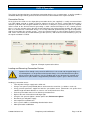
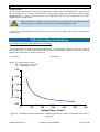
At the heart of the OVG-4 is the disposable permeation device (not supplied), is usually constructed from
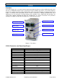
1/4” PTFE tubing and rod as shown in Figure 8; however the oven can house a permeation device with a
diameter up to 8mm and a length of 160mm. In the device is a two-phase system the first phase is a liquid or
solid reservoir of the desired chemical generating a stable saturated headspace in the second gaseous
phase. It is in this gaseous phase that the chemical dissolves into, and permeates through, the walls of the
tube at a constant rate. Permeation devices are usually calibrated gravimetrically for a given temperature
-1
with the permeation rate stated in ng min . Once the chemical vapour is released from the device it mixes
-1
-1
with, and is carried away by a known dilutant gas flow (ml min ) and the desired concentration (ng ml ) for
the vapour standard is created.
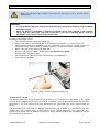
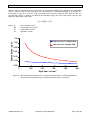
Figure 8 - Example of permeation device
Loading and Removing Permeation Devices
Important: Even though each part of the GEN-SYS is leak-tested and Swagelok fittings are
used throughout, it is not guaranteed leak-proof. Always refer to the Material Safety Data
Sheets relevant to the vapour(s) you are handling and ensure adequate risk controls and
COSHH are in place before using potentially hazardous vapours / gases with the OVG-4
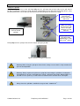
Loading a permeation source:
• Turn off power and gas supply to the OVG unit
• Using a 7/8” spanner (not provided) loosen and remove the oven inlet (½” Stainless steel nut)
• Using personal protective equipment load the permeation source (Dimensions no greater than
160mm length and 8mm diameter as sources can swell) into the oven inlet,
• Push the permeation source 3-5cm into the permeation oven
• Replace the oven inlet and turn until finger tight
• Using the 7/8” spanner tighten a further quarter turn, DO not over tighten
• Reconnect gas and power supply
• Set temperature and flow rates
• Once system stabilises acknowledge flow deviation alarm.
• Allow permeation stabilization
© 2008 Owlstone Ltd
Proprietary and Confidential
Page 13 of 20