1
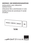
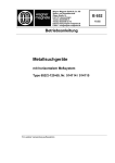
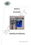
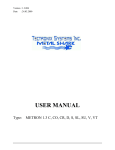
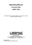
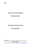
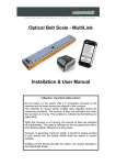
METAL DETECTOR
Type QLC/QLCTA
Operators Manual (English)
TECT-QLC_english-OP manual.doc
METAL DETECTOR QLC/QLCTA
System Information
Customer Name:
Location:
Date in Service d/m/y:
We would like to take this opportunity to thank you for purchasing your
Metal Detector from Tectronix. The confidence you have placed in our
product is sincerely appreciated and we will endeavour to provide the best
service and support possible.
Please take the time to read the User Manual completely as this
provides you with the expertise necessary to install and adjust the system according to your requirements. In addition to this, you will learn
about the sophisticated options provided by the METAL SHARK® electronics.
If you have any problems in the set up and operation of your system, the Tectronix team are available to assist you.
Tectronix Systems inc.
Unit 9 18812 - 96th Ave
Surrey , British Columbia
Canada, V4N 3R1
Equipment Information Label
Telephone: (001) 604 607-6028
Fax: (001) 604 607-6026
E-mail: [email protected]
-2-
METAL DETECTOR QLC/QLCTA
Instruction Manual - Metal Detector QLC/QLCTA
Contents
Page
1.
General
4
1.1
Design
4
1.1.1
Standard unit
4
1.1.2
Tandem unit
4
1.2
Function
4
Selecting the installation point and mounting
5
2.1
Selecting the installation point for the Sensor
5
2.2
Installation of detector (control box)
5
Preventing electrical interferences at the installation point
5
3.1
Mounting the single Sensor
5
3.2
Mounting the tandem Sensor
6
3.3
Eliminating electrical interferences at the installation point
11
Electrical connections
12
4.1
Power supply and control line
12
4.2
Single Sensor
13
4.3
Tandem Sensor
13
4.4
Attachment of the coaxial plug
13
4.5
Potential equalization line
14
Start-up
15
5.1
Turning on
15
5.2
Adjustment of the sensitivity
16
5.3
Selecting the relay output contacts
16
Specifications
18
6.1
Controller
18
6.2
Sensor
18
7.
Metal detecting device with single Sensor
19
8.
Metal detecting device with tandem Sensor
20
9.
Check list
21
10.
Spare Parts
22
11
Install Position Drawing
23
12
Warranty
24
2.
3.
4.
5.
6.
-3-
METAL DETECTOR QLC/QLCTA
Warning !
Before operating inside the Controller cabinet or inside the connection box switch
off power supply and control voltages
1. General
The Metal Detecting Devices type QLC and QLCTA
are especially developed for stone and earth industries. It is reliable, resistant and requires little maintenance. With this metal detecting device it is possible
to control material with a high percentage of metal
oxides like e. g. basalt, slag, magnetite, magnesium
oxide and blood-stone.
The metal detecting device protects your downstream
equipment with very little down time. It protects your
crusher, mills, mixing and extruder machines. The
metal detecting device detects all metal e.g. like
steel, iron, copper, aluminium, brass, stainless steel.
This manual describes the application in conveyor
plants.
1.1 Design
Fig. 1 Single Sensor in operation
The metal detecting device consists of two components, the Controller and the single Sensor (standard
unit) or the tandem Sensor. The Controller and the
Sensor are interconnected by one coaxial cable.
1.1.1 Standard unit
The standard unit consists of an Controller and Sensor with a plate like rectangular body. The Sensor is
manufactured for the width of the conveyor framework. All controls, on the Controller, required for operation of the unit are clearly arranged behind the
front door. This standard unit is designed for the
stone and earth industries, because this device is
stable within the surrounding metal construction of
the conveyor belt and against vibrations.
1.1.2 Tandem unit
The standard unit can be expanded to the tandem
unit by using another Sensor and two spacers. This
device has a very constant sensitivity at each point
between the two Sensors. It is used when there is a
high burden depth on the belt.
-4-
1.2 Function
An oscillator located in the Controller feeds the
Sensor a high frequency alternating voltage. This
voltage is fed to the Sensor by a 75 Ohm coaxial
cable. An electromagnetic alternating field is built
up vertical to the Sensor and penetrates the conveyor belt and the conveyed material. If a piece of
metal passes within the detection range of the Sensor, the oscillating circuit is slightly attenuated.
In the detector a pulse is filtered out of the amplitude surge, which switches an internal relay after
passing through an Controller.
The relay is the detector output. It has two potential
free nc/no-contacts, which can be used to stop the
conveyor belt, or give a warning signal, etc.
METAL DETECTOR QLC/QLCTA
2. Selecting the installation position for Sensor and detector
2.1 Sensor
2.2 Detector Control Cabinet
− Avoid positions where the conveyor belt is instable.
− The distance between two roller stages has to be at
least 1000 mm (40 inch)
− If the conveyor system is to be stopped when metal
is detected, it must be accessible for removal of the
metal parts.
− Take into consideration the distance the belt will
travel between stop signal, and actual stopping.
− Install far from electric motors and large metallic
moving parts, at least 1.0 m (40 inch).
− Protect Sensor from direct sunlight.
− Install the detector Control Cabinet in the
vicinity of the Sensor, e.-g. in the conveyor
system control room or outdoors at a position
protected from direct sunlight and rain.
− The standard length of the coaxial-cable (connection cable between Sensor and detector) is
10 m. Longer cables upon request.
3. Mounting the Sensor and eliminating electrical interferences
at the installation position
3.1 Mounting the single Sensor
Check that the serial numbers of Sensor and detector
Control Cabinet are the same. Mount the Sensor as
indicated in figure 1 and 2, whereby the cast pattern
should point upward. The clearance between the Sensor and the bottom of the belt should be 40-50 mm
(1.5 to 2 inch) corresponding to maximum belt sag
expected. Angular brackets and U channels should be
used to mount the Sensor to achieve a high degree of
positional stability and eliminate distortion.
-5-
Conveyor belt which shakes or sags must be stiffened at the position where the Sensor is installed.
Any type of installation deviating from the above
should be discussed with the supplier beforehand.
It is important that the Sensor is connected solidly
with the conveyor belt construction and the no
movement is possible relative to the surrounding
metal construction.
METAL DETECTOR QLC/QLCTA
3.2 Mounting the tandem Sensor
Check that the serial numbers of Sensor and detector
Control Cabinet are the same. The tandem Sensor
should be assembled as indicated in figure 1 and 2.
When mounting the Sensor, consider the following:
− Mount the Sensor at the midpoint between two
roller stages.
− The cast patterns of the two Sensors must be
mounted face to face.
− The clearance between lower Sensor and loaded
belt should still be 40-50 mm (1.5 to 2 inch)+ if
maximum belt sag may occur.
− The upper Sensor must be mounted exactly
above the lower Sensor.
− Connect upper to lower Sensor by use of the
short inter-connection cable (6)
− The distance between the upper Sensor and
the belt depends on the maximum height of
the burden on the belt.
− If used outdoors the Sensor should be protected from direct sunlight. (Install a little
wooden or plastic roof, if necessary.)
In order to achieve a high degree of sensitivity,
the distance between the two Sensors and the
belt should be kept as small as possible.
In case of doubt send a drawing of the intended
installation position to Tectronix for evaluation.
Fig. 1 Assembling the tandem Sensor
Join parts firmly together
no. 1 to 4 by means of 4
threaded rods M10
Weld together
parts no. 4 and 5
1 lower Sensor
2 upper Sensor
3 support for upper Sensor
4 spacer
5 frame of conveyor
6 inter-connection cable
7 bore hole
11 mm ∅
Attention!
Always use the original coaxial cable from Tectronix.
Do not use any other coaxial cables.
-6-
METAL DETECTOR QLC/QLCTA
Fig. 2 Build in example for U-Frame-Conveyor-Belts
Rollers can alternatively be prepared with insulating sleeves, according Fig. 6, page 10
-7-
METAL DETECTOR QLC/QLCTA
Fig. 3 How to build in a tandem Sensor in U-Frame construction
-8-
METAL DETECTOR QLC/QLCTA
Fig. 4 Mounting example for pipe frame construction
-9-
METAL DETECTOR QLC/QLCTA
Fig. 5 How to build in a tandem Sensor in a pipe frame construction
- 10 -
METAL DETECTOR QLC/QLCTA
Fig. 6 Eliminating electrical interferences by insulating sleeves
3.3 Preventing electrical interferences at
the installation point
It is important to keep away electrical interferences
from the Sensor in order to ensure adequate sensitivity, and to avoid false alarms.
The most important measures to prevent electrical
interferences are shown in Fig. 2 to 6.
− Wobbly or sagging conveyor belts must be stiffened
at the installation point.
− Metal cover plates, metal roofing, and metal guide
plates between the adjacent roller stages must be
removed or replaced by wood or plastic parts.
− Return rollers are to be removed in this area.
− Cover plate edges and margins should be welded
to the frame if they extend into this area.
− The adjacent rollers should be prepared either with
short-circuiting shields acc. Fig. 2 or with plastic
sleeves acc. Fig. 6.
− If very high sensitivity is not required, interference
prevention can be done by means of short circuit
brackets (see Fig. 2 and 4).
− The adjacent roller stages are to be welded to the
frame of conveyor belt. If they are already bolted
onto their support, a short welding joint (about 15
mm) will be sufficient.
− All bolted and riveted connections within 2 m from
the Sensor should be secured with short welding
joints.
Note:
Bolted and riveted connections are unpredictable
contacts for electrical currents that are known to
raise problems in the vicinity of the Sensor. The additional short welding joints will solve these problems.
Preparation of rollers is required either with insulating sleeves or with short-circuiting brackets
- 11 -
METAL DETECTOR QLC/QLCTA
4. Electrical connections
4.1 Power supply, control line, coaxial cable
Please make note of power supply voltage and output
identification from the specifications. Connect line
voltage to terminals L1, N and PE. The range of voltage fluctuations shouldn’t exceed 15 %. Connect control line to terminal from relay K1 (see Fig. 7). In Fig. 7
the relay contacts are shown in the no-current state.
By means of slide switch S2 on the circuit board (see
section 5.3) you can decide whether the relay normally
carries no electrical current and is actuated upon
metal detection, or if the relay is normally actuated
(safety position) and is de-actuated upon metal detection.
The two control lines can be used for conveyor
stop, conveyor reverse, or to activate an ejecting
device. Fig. 7 shows an example for the function
"conveyor stop". In this case the output relay
works in the normally de-actuated mode.
The metal detecting device requires only one
coaxial cable to connect Sensor and Controller.
Install the coaxial cable in a plastic conduit and
install separately from other current-carrying cables. A distance of 20 cm is normally enough.
Important: Do not confuse hot and ground connection on Controller-terminal strip.
Fig. 7 Connection example with additional wiring "locking circuit"
- 12 -
METAL DETECTOR QLC/QLCTA
Fig. 8 and 9 Attachment of the coaxial plug
4.2 Single Sensor
Connect the coaxial cable to the Controller as shown
in Fig. 7. Screw the coaxial plugs into the corresponding sockets at the Sensor; by hand power, without
using a tool.
4.3 Tandem Sensor
Use the inter-connection cable to connect upper and
lower Sensor. Other connections as with the Single
Sensor.
Important: Do not confuse hot and ground connection
on Controller-terminal strip.
4.3 Attachment of the coaxial plug
Prepare the coaxial cable without damaging the
braided shield. Insert the middle conductor and
braided shield in the coaxial plug and solder middle
conductor (see fig. 8 and 9). Use a soldering iron with
a constant temperature tip.
Note: Attachment of the coaxial-plug must be done
very careful. All individual wires in the braided shield
must remain together under all circumstances.
Attention! Always use the original coaxial cable from
Tectronix. Don’t use any other coaxial cables.
- 13 -
METAL DETECTOR QLC/QLCTA
4.5 Potential Equalization Line
To this:
In spite of the fact that the conveyor and the Controller
are connected to the grounded wire, there are often
high peak potentials between these two devices. The
metal detecting device reacts with false alarm. With a
direct potential equalization line these potential differences are shorted and removed.
− Use a contact area close to the Sensor. Clean
contact surface very well and use a tooth lock
washer.
− Connect to the grounding screw in the Controller.
− Cross-cut of the potential equalizing line
should be 2,5 mm2 (4/1000 inch 2) minimum
Note: Do not lay the potential equalization line
together with current carrying lines. Lay it together with the 75 ohm coaxial cable.
Fig. 10 Installation of the Potential equalization line
- 14 -
METAL DETECTOR QLC/QLCTA
Fig. 11 Operating and controlling elements of the Controller
5. Start-up
5.1 Turning on
After connecting the Sensor, the power supply, and
the control cable, the unit should be started up as follows: Switch on the power voltage - the LED indication
line will light up. Dependent on adjustment sensitivity
the red LED indicator "metal" may light up briefly. After
about 20 seconds the unit will be ready for operation.
The slide switches can be shifted with a screw driver
without dismount the front plate. This should be done
carefully.
Shift the selector switch S3 into position "adjustment".
The LED indication line should read between 30 and
70 µA.
- 15 -
The slide switches can be shifted with a screw driver
without dismount the front plate. This should be done
carefully.
Shift the selector switch S3 into position "operation".
The LED indication line should read 50 µA.
During the operation of the metal detectior the
selector switch S3 should be left in position "operation".
In this position the control instrument gives information about the general operating state:
As long as the pointer remains relative quite the unit
will work well. Restless movements of more than
10 % can indicate noise influences.
METAL DETECTOR QLC/QLCTA
5.2 Adjustment of the sensitivity
5.3 Setting the slide switches S 1 and S 2
The right position of sensitivity control is very important
for operation: A too low sensitivity endangers the machinery to be protected, while a too high sensitivity will
cause unnecessary conveyors stops, or material ejections respectively.
The slide switches can be shifted with a screw driver
without dismount the front plate. This should be done
carefully.
− Select a test piece that will correspond to the
smallest metal piece to be detected, like a nut.
− Attach a rope to the test piece.
− Turn the unit on, and put selector switch S3 into
position "operation". Empty the conveyor belt, and
turn off the conveyor.
− Pull the test piece with help of the rope repeatedly
through the Sensor tunnel - with approximate belt
speed. Adjust first-sensitivity control step by step
until the test piece is detected - but smaller pieces
of metal remain undetected.
− Let the conveyor run, without product.
− Watch the LED indicator line: If no pieces of metal
pass through the Sensor area the LED indicator
line should stay in the range of 45 to 55 µA. (It is
recommended to connect the unit to the light net.)
The LED indicator line may move between 45 and 55
µA only, if no metal piece passes the Sensor. If there
are larger deviations, especially if false alarms occur,
the following points should be checked for sources of
interference.
- mechanical preparations, page 6 to 10
- coaxial cable and potential equalizing line, page 11
and 13
- power supply, page 17
For instance:
Have insulating sleeves, and short-circuit brackets
been installed? Have the adjacent roller stages been
welded to the frame of conveyor? Have the coaxial
cables been secured properly?
If interferences still persist, Tectronix will gladly answer your questions. Tectronix will request the serial
number and the LED indicator line readings for the two
positions of the selector switch S3.
− Let the conveyor run with product.
− Repeatedly throw the test piece into the conveyed
material and readjust sensitivity if necessary.
Attention!
Make sure that the conveyor belt can be stopped
manually if necessary
- 16 -
Slide switch S1 in position 1:
Operation-Mode: A metal detection will activate the
contacts of the out put relays K1.
Slide switch S1 in position 2:
Test- Mode: The relay K1 remains in the state selected by S2 and will not respond any more. Only the
red LED-indicator „Metal“ will report metal pieces.
Attention: During operation the switch S1 must
be shifted to position 1.
Slide switch S2 in position 1:
Normally relaxed mode, that is the relay will be
activated for about 0.5 seconds on metal detection,
and will thereafter resume the relaxed state.
Slide switch S2 in position 2:
Normally activated mode, the relay will be activated on turning on the unit, will relax for about 0.5
seconds on metal detection, and will thereafter resume the activated state. In this mode power failure
will put the relay in the metal detection state and a
duration alarm is given.
The contacts on the terminal from relay have to be
wired according to the selected position of S2 (see
section 4.1). The unit leaves the factory in the normally relaxed mode.
METAL DETECTOR QLC/QLCTA
Fig. 12 Internal connection diagram
- 17 -
METAL DETECTOR QLC/QLCTA
6. Specifications
6.1 Controller
Power voltage
Power requirements
Admissible belt speeds
Admissible ambient temperature
Inputs
Outputs
• Metal detection
100-240 V / 50-60 Hz +/- 15 %
15 VA
0,3 - 4,0 m/s
(other speeds upon request)
-20° C to +55° C
1 coaxial cable, Sensor
1 relay with 2 potential free nc/no-contacts for 230 V / 6 A
resistive load; choice of normally relaxed mode or normally
activated mode
Housing
Protective device classification IP 55, sheet steel, treated
by electrophoresis dip primer coating colour: RAL 7032
grey
• Mounting
• Weight
• Dimensions
Wall mounting
9 kg
see figure
Use of other operational requirements may be possible upon request.
6.2 Sensor
Design
Material
Admissible ambient temperature
Single Sensor: bulk rectangular plate with built-in induction
coils. Flange-attached coaxial socket for electrical connection. Tandem Sensor: like above, but with 2 support parts
and electrical connections in terminal box.
Sensor body out of PVC, PE or PA6.6, coils cast into 2component resin.
PE version from -30° C up to +70° C
PA6.6 version from -50° C up to 120° C
- 18 -
METAL DETECTOR QLC/QLCTA
7. Metal detecting device with single Sensor
1 detector
1 Sensor
1x 10 m special coaxial cable, 75 ohm surge impedance
............ mm, other sizes on application
............ mm clearance between belt and lower Sensor
Components you need for
metal detecting devices with
single Sensors:
Nominal sizes:
Installation:
Single Sensor
Nominalsizes
500
650
800
1000
1200
1400
1600
1800
2000
A
B
C
D
for belt
width up to
weight
mm
700
850
1000
1250
1500
1700
1900
2100
2300
mm
400
400
400
500
500
500
500
650
650
mm
640
790
940
1170
1420
1620
1820
2020
2220
mm
260
260
260
300
300
300
300
300
300
mm
500
650
800
1000
1200
1400
1600
1800
2000
kg
18,0
23,6
28,0
43,5
52,0
59,5
96,0
129,5
142,5
Other sizes on request.
- 19 -
METAL DETECTOR QLC/QLCTA
8. Metal detecting device with tandem Sensor
1 detector
2 Sensors
2 special supports
1x 10 m special coaxial cable, 75 ohm surge impedance
............ mm, other sizes on application
............ mm clearance between belt and lower Sensor
Components you need for
metal detecting devices with
tandem Sensors:
Nominal sizes:
Installation:
Tandem Sensor
Nominalsize
500
650
800
1000
1200
1400
1600
1800
2000
A
B
C
D
L
for beltwidth up to
appr.
weight
mm
700
850
1000
1250
1500
1700
1900
2100
2300
mm
400
400
400
500
500
500
500
650
650
mm
640
790
940
1170
1420
1620
1820
2020
2220
mm
260
260
260
300
300
300
300
300
300
mm
600
750
900
1150
1400
1600
1800
2000
2200
mm
500
650
800
1000
1200
1400
1600
1800
2000
kg
46,0
57,0
66,0
100,0
118,0
147,0
227,0
296,0
321,0
Other sizes on request. H = according to requirement.
- 20 -
METAL DETECTOR QLC/QLCTA
9. Check list
Checklist for points for preventing electrical interference’s
if mounting the Sensor at a U-structural-iron-conveyor-frame
- if not specified differently -
1.
Minimum-distance between upper rollers and middle of Sensor: 500 mm (20 inch)
2.
Minimum-distance between lower rollers and middle of Sensor: 500 mm (20 inch)
3.
Distance between lower Sensor and loaded belt: approximately. 50 mm. (2 inch)
4.
Remove out of the area under the Sensor all kinds of diagonal- and crossbeams.
5.
Structural iron for Sensor mounting is to be welded to the conveyor-frame.
6.
All diagonal- and crossbeams within the area of 1000 mm (40 inch) around the Sensor are to be welded, not screwed, to the frame.
7.
One roller stage before and one after the Sensor is to be welded to the frame.
8.
For one roller stage before and one after the Sensor: provide the roller axle with insulating sleeves-required on one side only of each roller or prepare with short circuit brackets
9.
Roller stages of lower rollers are to be mounted to a minimum distance of 1000 mm
(40 inch) to the Sensor.
10.
Axles of lower rollers of point 9 are to be prepared, either with insulating sleeves,
according point 8, if distance to the Sensor is less than 1000 mm. (40 inch)
11.
The floor-legs, one before and one after the Sensor, are to be welded to the frame, if
distance to the Sensor is less than 1000 mm. (40 inch)
12.
Line for emergency stop will not influence the Sensor, if installed beside the Sensor.
13.
Roof-covering plates over the conveyor belt or between upper and lower conveyor belt
should be made out of not conducting material in the area at 1000 mm(40 inch) before and 1000 mm (40 inch) after the Sensor. Structural iron supports for roofcovering are allowed, but all parts of it should be welded with each other.
14.
A potential equalisation line is to be connected between conveyor frame and earth
terminal of Controller. See section 6.4
15.
Install coaxial-cable separately from other loaded cables, except cable for potential
equalisation. The potential equalisation line should be installed together with the coaxial-cable in one plastic conduit. Crossing other loaded cables is allowed but no installations less than 1 m (40 inch) parallel to those loaded cables.
Moreover it is important to take into consideration the mounting-instruction bulletin.
- 21 -
METAL DETECTOR QLC/QLCTA
10 Spare Parts
SPARE PARTS
op.
ITEM
Name
date
Burau
17.07.03
DESCRIPTION
1
F1 0,2 T
2
K1
3
4
Type
QLC / QLCTA
PLACE QUANTITY
G - type fuse 1,0 T
TYPE AND ORDER NO.
1
F01.100
1
EAB-RP 821012
POWER - CIRCUIT BOARD
1
NT 03/01 qlc
CONTROLLER - CIRCUIT BOARD
1
QLC 004 CD
RELAY
- 22 -
11 Install Position Drawing
A
6
13
8
3
50
8
50
Gurt
belt
7
5
1
2
- 23 -
9
7
A-A
Bandrahmen
conveyor frame
1
2
METAL DETECTOR QLC/QLCTA
11
11
10
10
9
A
Sonde
probe
6
4
12
Bedeutung der Numerierung: siehe Checkliste
numbering: see checklist
6
Bearb.
Datum
15.04.99
Gepr.
Norm
Freig.
Name
F. Burau
Benennung
Einbauvorschlag Einzel- u. Tandemsonde in
U-Profilrahmen
install proposition single and tandem probe in
U-structual conveyor frame
Zeichnungsnummer
Zust.
─nderung
Datum
Name
Ma▀stab:
%
Blatt
6204_B20
1/1
A4
METAL DETECTOR QLC/QLCTA
12. Warranty
•
Your METALSHARK metal detector is designed to the most stringent manufacturing
specifications to insure a long life in your industrial environment,
•
Your METALSHARK detector us warranted against defects in materials and or workmanship
a. TWO year warranty on detector sensor head
b. ONE-year warranty on electronics
Tectronix will repair or replace the defective component at its discretion
- 24 -
METAL DETECTOR QLC/QLCTA
TECTRONIX SYSTEMS INC.
th
9 – 18812 96 Ave
Langley, British Columbia, Canada
Tel.: +11(604)607-60280
Fax.: +11(604)607-6026
www.metal-shark.com
Email: [email protected]
- 25 -