1
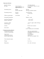
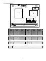
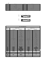
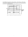
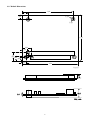
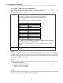
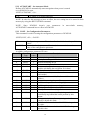
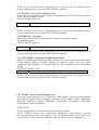
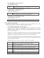
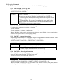
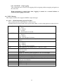
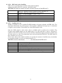
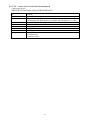
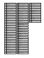
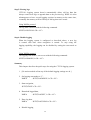
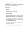
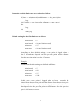
PCM-3292
PC/104 GPS Module
Users Manual
Contents
1.0 Connectors Defined ........................................................................................................................ 4
2.0 Jumper Settings.............................................................................................................................. 6
3.0 TMARK ........................................................................................................................................... 6
4.0 Module Dimensions ........................................................................................................................ 8
5.0 NMEA Protocol ............................................................................................................................... 9
5.1 General NMEA Commands ............................................................................................................ 9
5.1.1 START – Start Navigation .................................................................................................... 9
6.1.2 STOP – Stop Navigation .................................................................................................... 10
5.1.2 PWRDOWN – PCM3292 Sleep Mode ............................................................................... 10
5.1.3 SW – PCM3292 Software Revision.................................................................................... 10
5.2 Configuration Commands ............................................................................................................. 11
5.2.1 NMEA – NMEA Serial Communication .............................................................................. 11
5.2.2 AUTOSTART – Set Autostart Mode................................................................................... 12
5.2.3 CONF – Set Configuration Parameters.............................................................................. 12
5.2.4 DATUM – Set Local Coordinate System ............................................................................ 13
5.2.5 FIXRATE – Set Fixrate ....................................................................................................... 13
5.2.6 SYNCMODE – Synchronous NMEA Output Mode ............................................................ 13
5.2.7 STORE – Store Current Parameter Set ............................................................................. 13
5.2.8 RESETDATA ...................................................................................................................... 14
5.2.9 RESTORE – Restores Default Parameter Set ................................................................... 14
5.3 PPS Mode Commands ................................................................................................................. 15
5.3.1 PPSMODE – Set Pulse Per Second Mode ........................................................................ 15
5.3.2 PPSPOS – PPS Static Mode Antenna Position ................................................................. 15
5.3.3 SURVEYLEN – PPS Survey Period Length....................................................................... 15
5.3.4 CABLEDEL – Set PPS Cable Delay .................................................................................. 16
5.3.5 PULSEPOL – Set PPS Pulse Polarity................................................................................ 16
5.3.6 PULSELEN – Set 1PPS Pulse Length ............................................................................... 16
5.4 Navigation Aiding Commands ...................................................................................................... 16
5.4.1 INITAID – Initial Position And Time Aiding ......................................................................... 16
5.4.2 ALTAID – Set The Altitude Aiding Mode ............................................................................ 17
5.4.3 SETLIMIT – Set Limits For Altitude, Velocity And Acceleration ......................................... 17
5.5 Logging Commands...................................................................................................................... 18
5.5.1 LOGCLEAR – Clear log data ............................................................................................. 18
5.5.2 LOGFREE – Amount of free space for log data................................................................. 18
5.5.3 LOGGET – Output logged data.......................................................................................... 18
5.5.4 LOGINFO – Show log information...................................................................................... 18
5.5.5 LOGMODE – Set logging start mode ................................................................................. 19
5.5.6 LOGNAME – Set log name ................................................................................................ 19
5.5.7 LOGNUM – Get number of logs ......................................................................................... 19
5.5.8 LOGSETTING - Set logging settings.................................................................................. 19
5.5.9 LOGSTOP – Stop Logging................................................................................................. 20
6.0 NMEA Message............................................................................................................................ 20
6.1 GGA – Global Positioning System Fix Data ................................................................................. 20
6.2 GSA – DOP And Active Satellites ................................................................................................ 21
6.3 GSV – Satellites In View............................................................................................................... 21
6.4 RMC – Recommended Minimum Specific GNSS Data................................................................ 22
6.5 VTG – Course Over Ground And Ground Speed ......................................................................... 23
7.0 Appendix: Datum IDS ................................................................................................................... 24
8.0 Appendix Agenda ......................................................................................................................... 26
8.1.1 PWRDOWN command procedure:..................................................................................... 26
INITAID – Initial position and time aiding .................................................................................... 28
9.0 Overview ....................................................................................................................................... 31
10.0 QUICK START............................................................................................................................ 32
11.0 LOGGING SETTINGS ................................................................................................................ 35
12.0 DOWNLOADING LOGGED DATA TO HOST ............................................................................ 38
13.0 NMEA PROTOCOL SUPPORT.................................................................................................. 39
14.0 USAGE CONSIDERATIONS...................................................................................................... 40
2
Major Specifications
Satellite Tracking
RF input
Center frequency
Characteristics impedanc
Signal sensitivity
12 Parallel channels
1575.42MHz L1 band, C/A code
50 ohm
-145 dBm
Positioning system
Default
Software Selectable
WGS-84
All major coordinate systems
Positioning accuracy
Position
Velocity
10 m CEP (50%)
0.2m/s (50%)
Follow-up performance
Acceleration
4G
Navigation Update Rate
Default 1 second
Operation Temperature
Storage Temperature
-40°C to 85°C
-40°C to 95°C
Operating voltage
Antenna supply
+5V±5%, ripples within 50mVp-p
3.3V
Antenna
External, active antenna
Power drain
160mA
(Active antenna power not included)
Communication Specification
Communication method
Transfer rate input/output
Logic levels
Communication format
Default Output Message.
Start-stop synchronization
2400/4800(Default)/9600/19200
/115200bps
TTL compatible
NMEA-0183
GGA, GSA, GSV, RMC, VTG
Time mark pulse output :
1 PPS
Weight:
less 110 g
Dimensions:
95.9 ×90.2 ×28.6 mm
3
1.0 Connectors Defined
JP1
10
6
J7
1
5
ANT
J3
Module
U1
U2
Table2
Table1
B1
A1
Table3
J4
C1
D1
J5
Table 1
PIN No
JP8
JP9
JP11
JP12
PIN Name
IRQ3
IRQ4
IRQ5
IRQ7
PIN No
JP13
JP14
JP16
JP17
PIN Name
IRQ3
IRQ4
IRQ7
IRQ10
PIN No
JP18
JP19
JP20
JP21
PIN Name
IRQ11
IRQ12
IRQ14
IRQ15
Table 2
PIN No
JP4
JP7
PIN Name
COM1
COM4
PIN No
JP5
PIN Name
COM2
PIN No
JP6
PIN Name
COM3
Table 3
PIN No
JP10
JP1
PIN No
JP1
PIN Name
External Interrupt Setting
PIN No
JP15
PIN Name
Time Mark Output Setting
4
PIN Name
IRQ5
J7
PIN No
PIN Name
1
NC
3
NC
5
GND (Power)
7
NC
9
Time Mark Pulse (1PPS)(I)
PC/104 connectors (J4,J5)
1
PIN No
2
4
6
8
10
PIN Name
NC
NC
NC
NC
VCC (Power)
J4
2 •••••31 32
Row B
•••
Row A
1
1
2 •••••31 32
J5
2 •••••19 20
Row C
•••
Row D
1
2 •••••19 20
PC/104 connectors
PIN No
1
2
3
4
5
6
7
8
9
10
11
12
13
14
15
16
17
18
19
20
21
22
23
24
25
Signal (J4)
Row A
Row B
IOCHCHK*
0V
SD7
RESET
SD6
+5V
SD5
IRQ9
SD4
-5V
SD3
DRQ2
SD2
-12V
SD1
ENDXFR*
SD0
+12
IOCHRDY
(KEY)
AEN
SMEMW*
SA19
SMEMR*
SA18
IOW*
SA17
IOR*
SA16
DACK3*
SA15
DRQ3
SA14
DACK1*
SA13
DRQ1
SA12
REFRESH*
SA11
SYSCLK
SA10
IRQ7
SA9
IRQ6
SA8
IRQ5
SA7
IRQ4
SA6
IRQ3
5
Signal (J5)
Row C
Row D
0V
0V
SBHE*
MEMCS16*
LA23
IOCS16*
LA22
IRQ10
LA21
IRQ11
LA20
IRQ12
LA19
IRQ15
LA18
IRQ14
LA17
DACK0*
MEMR*
DRQ0
MEMW*
DACK5*
SD8
DRQ5
SD9
DACK6*
SD10
DRQ6
SD11
DACK7*
SD12
DRQ7
SD13
+5V
SD14
MASTER*
SD15
0V
(KEY)
0V
―
―
―
―
―
―
―
―
―
―
26
27
28
29
30
31
32
SA5
SA4
SA3
SA2
SA1
SA0
0V
*Low active
DACK2*
TC
BALE
+5V
OSC
0V
0V
―
―
―
―
―
―
―
―
―
―
―
―
―
―
2.0 Jumper Settings
Serial Port Select
Jump No
Define
Note
JP4
COM1
Short :Enable ; Open :Disable
JP5
COM2
Short :Enable ; Open :Disable
JP6
COM3
Short :Enable ; Open :Disable
JP7
COM4
Short :Enable ; Open :Disable
Jump No
Define
Note
JP8
IRQ3
Short :Enable ; Open :Disable
JP9
IRQ4
Short :Enable ; Open :Disable
JP11
IRQ5
Short :Enable ; Open :Disable
JP12
IRQ7
Short :Enable ; Open :Disable
Interrupt Port Select
The default setting is COM3, IRQ5 Enable.
Enhance
Jump No
Define
Note
JP13
IRQ3
Short :Enable ; Open :Disable
JP14
IRQ4
Short :Enable ; Open :Disable
JP15
IRQ5
Short :Enable ; Open :Disable
JP16
IRQ7
Short :Enable ; Open :Disable
JP17
IRQ10
Short :Enable ; Open :Disable
JP18
IRQ11
Short :Enable ; Open :Disable
JP19
IRQ12
Short :Enable ; Open :Disable
JP20
IRQ14
Short :Enable ; Open :Disable
JP21
IRQ15
Short :Enable ; Open :Disable
Note: If you want to add on Enhance part, please setting the jump of JP10 at
enable before setting JP13~JP21.
3.0 TMARK
6
The TMARK pulse waveform is shown in Figure 1. This signal is a positive logic ,
buffered CMOS level output pulse that transitions from a logic “low” condition to a logic “high”
at a 1 Hz rate. The TMARK output pulse rise times typically less than 2 nanoseconds and the
pulse duration is typically 25milliseconds.
1
ch1 +Width
25ms
ch1
2.00V
M5.00ms
ch1
3.56V
Figure 1. GPS Receiver Time Mark Pulse Waveform.
7
4.0 Module Dimensions
3250
350
∮250
200
∮125
3775
1050
250
500
300 200
200
3550
Unit:mil
16.5
28.6
1.6
Unit : mm
8
5.0 NMEA Protocol
NMEA Commands
This chapter describes the supported NMEA commands.
5.1 General NMEA Commands
The following sections introduces the general-purpose NMEA commands the basic PCM3292
operations.
5.1.1 START – Start Navigation
Commands PCM3292 to start navigation. The command has no effect if called while
PCM3292 is already navigating. After the start command has been given, it takes some time
for PCM3292 to acquire satellites, gather data from the signal and calculate a first fix.
$PFST,START,<startmode>
<start mode>
Navigation start modes:
0=Autostart. Always uses the fastest possible start mode (1-4). Default
value.
1=Force cold start. Module will behave as if no valid ephemeris or PVT
data were available.
2=Request warm start.
3=Request hot start. Requires RTC time, valid ephemeris and PT data.
Calculates a fix as soon as PS time is acquired from the GPS signal.
4=Request quick start. Requires RTC time and recent ephemeris.
Assumes that RTC time is very accurate and doesn’t wait for GPS
time.
Notice that if the host requests faster start mode than possible (e.g. hot
start when there is no ephemeris data available) start mode 0 will be
used.
RTC time is available if the module has already been navigating after
the previous power-up, or if the time has been given by using the
$PFST,INITAID command.
Valid ephemeris data is available if the module has been navigating
within the last two hours and the navigation has been stopped properly
by giving the $PFST,STOP command.
9
6.1.2 STOP – Stop Navigation
Commands PCM3292 to stop navigating and enter the idle state. While in idle state, the
PCM3292 receiver doesn’t navigate but still accept commands., less power is consumed in
the idle state than in the navigation state; however, remarkably more than in the power-down
mode. This command also stores the “LastKnownGood” fix, ephemeris and almanac data in
flash memory.
$PFST,STOP,<1|0>
<1|0>
1 to save, 0 not to save “LastKnownGood” fix, ephemeris
and almanac data to flash memory.
5.1.2 PWRDOWN – PCM3292 Sleep Mode
Commands PCM3292 to sleep mode.
Using the sleep mode is recommended when navigation isn’t needed. PCM3292 consumes
remarkably little power in the sleep mode and still re-acquires the navigation fix quickly
after waking up.
PCM3292 wakes up from the sleep mode when the timeout has expired. If the receiver was
navigating when the PWRDOWN command was given, navigation will restart automatically
after waking up from the sleep mode.
$PFST,PWRDOWN,<hours>,<minutes>,<seconds>
5.1.3 SW – PCM3292 Software Revision
Shows the firmware revision of the PCM3292 module.
10
5.2 Configuration Commands
The following sections introduce the commands used for controlling the behavior of PCM3292.
5.2.1 NMEA – NMEA Serial Communication
Sets the NMEA message mask and NMEA serial port communication speed. This message
mask defines which of the NMEA messages are being outputted.
$PFST,NMEA,<mask>,<speed>
<mask>
NMEA messaging mask bitmap in hexadecimal notation. If
it’s desired to change only the speed while keeping the
old message mask, this parameter may be omitted and
use “,,” instead.
Mask bits for message are defined as follows:
Message
GSV
GSA
ZDA
PPS
FOM
Reserved*
GLL
GGA
VTG
RMC
<speed>
bit
0x0001
0x0002
0x0004
0x0010
0x0020
0x0040
0x1000
0x2000
0x4000
0x8000
I.e. to allow GLL and RMC messages one would set mask as 0x1000 +
0x8000 = 0x9000. See examples below.
Note that hexadecimal digits A, B, C, D, E and F must be in capital
letters.
* Enables a message used for special purposes.
Communication speed. Either 1200, 2400, 4800, 9600,19200, 57600 or
115200.
NOTE 1:
Using message mask FFFF (command $PFST,NMEA,FFFF)is not recommended. Although
it may be used to turn on all messages, the side effect of this would be that all new messages
in future PCM3292 versions will also be turned on. The following messages are enabled by
default: GGA, RMC, GSA, GSV.
NOTE 2:
NMEA Serial port settings other than speed cannot be changed. The settings for the port are:
- Default speed 4800 bps
- No parity (cannot be changed)
- 8 data bits (cannot be changed)
- 1 stop bit (cannot be changed)
NOTE 3:
In order to preserve this setting after reset or power-up, the new setting has to be stored in
flash memory by using the $PFST,STORE command.
11
5.2.2 AUTOSTART – Set Autostart Mode
Defines if PCM3292 automatically starts navigation when power is turned
on or PCM3292 is reset.
$PFST,AUTOSTART,<1|0>
<1|0>
1 to enable, 0 to disable autostart.
NOTE: In order for this message to have an effect, the new setting has to be stored in flash
memory by using the $PFST,STORE command.
NOTE: Since PCM3292 doesn’t save parameters
AUTOSTART command has no effect in PCM3292.
in
non-volatile
memory,
5.2.3 CONF – Set Configuration Parameters
This command is used for setting the configuration parameters of PCM3292.
$PFST,CONF,<ID>,<VALUE>
<ID>
<VALUE>
Configuration parameter ID number. See the table below for possible
values.
New value for the parameter. If omitted, the command shows the current
value of the configuration parameter.
Available configuration parameter ID’s are:
Param ID
Param. Default
Description
Type
value
1
BOOL
1
Position pinning on/off (1=on)
3
BOOL
1
Velocity smoothing on/off
4
BOOL
1
Position smoothing on/off
10
BOOL
1
Carrier smoothing on/off
17
BOOL
0
Route nav- & msg-task messages to host
(enables calculating the navigation fix in host)
45
WORD
12 Number of receiver channels
47
BOOL
0
Disable fast search (=> uses slower but more sensitive
search mode)
48
WORD
7000 Acq search window width (Hz, from middle of the
window)
50
DOUBLE
5
Timeout for resetting the post filters
51
DOUBLE
0.4 Coefficient for position smoothing, high
52
DOUBLE 0.12 Coefficient for position smoothing, low
53
DOUBLE 0.0001 Velocity filter coefficient, low limit
54
DOUBLE
0.5 Velocity filter coefficient, high limit
55
DOUBLE
3.0 Pinning lag criteria (meters). In pinning mode, the
position may lag behind the actual position by this
amount.
59
DOUBLE
1.0 Pinning velocity limit. Goes to pinning mode if
velocity is below this limit.
70
DOUBLE
50 FOM limit. Fix is marked invalid if FOM is larger than
this value.
71
DOUBLE
22 HDOP limit. Fix is marked invalid if HDOP is larger
than this value.
12
NOTE: In order to preserve this setting after reset or power-up, the new setting has to be
stored to flash memory by using the $PFST,STORE command.
5.2.4 DATUM – Set Local Coordinate System
Selects the local coordinate system. After this command, the PCM3292 will return positions
in the selected coordinate system.
$PFST,DATUM,<datum_id>
<datum_id>
Coordinate system id. See appendix for supported DATUM id’s.
NOTE: In order to preserve this setting after reset or power-up, the new setting has to be
stored to flash memory by using the $PFST,STORE command.
5.2.5 FIXRATE – Set Fixrate
Defines how often PCM3292 should acquire navigation fix and thus output
the NMEA messages.
$PFST,FIXRATE,<fixrate>
<fixrate>
Number of seconds to between navigation fixes
NOTE: In order to preserve this setting after reset or power-up, the new setting has to be
stored to flash memory by using the $PFST,STORE command.
5.2.6 SYNCMODE – Synchronous NMEA Output Mode
Enables or disables the synchronous NMEA output mode. In the synchronous output mode,
all the enabled NMEA navigation messages are outputted approx. once per second,
regardless of the availability of a valid navigation fix. The synchronous mode is enabled by
default.
$PFST,SYNCMODE,<mode>
<mode>
Set synchronous mode on or off, 0 = off, 1 = on (default).
NOTE: In order to preserve this setting after reset or power-up, the new setting has to be
stored to flash memory by using the $PFST,STORE command.
5.2.7 STORE – Store Current Parameter Set
Stores the current parameter set in PCM3292’s flash memory. These parameters include
those that are defined by the commands, ALTAID, AUTOSTART, CONF, CABLEDEL,
DATUM, FIXRATE, NMEA, PPSMODE, PULSEPOL, PULSELEN, SETLIMIT,
SURVEYLEN, and SYNCMODE.
$PFST,STORE
NOTE: Navigation has to be stopped before giving this command.
NOTE: PCM3292 doesn’t store configuration parameters in flash memory, and thus
this command doesn’t have any effects on the PCM3292 modules. For PCM3292, the
preferred way is to set parameters each time, when the module is reset or switched on.
13
5.2.8 RESETDATA
Erases the navigation data stored in the flash memory, i.e. erases the last good known
navigation fix, ephemeris, almanac and UTC/Ionosphere model data. The module has to be
reset after this command to abandon all the above data; otherwise, some of the data may still
reside in RAM memory.
$PFST,RESETDATA
NOTE: Navigation has to be stopped before giving this command.
NOTE: This command doesn’t affect logged data. Log data is cleared with
$PFST,LOGCLEAR command.
5.2.9 RESTORE – Restores Default Parameter Set
Restores factory default parameter set.
$PFST,RESTORE
NOTE: Navigation has to be stopped before giving this command.
NOTE: PCM3292 doesn’t store configuration parameters to flash memory, and thus
this command is irrelevant with PCM3292 module.
NOTE: This command doesn’t affect the last good navigation fix, ephemeris,
UTC/ionosphere model data or log data. Navigation, ephemeris and model data is
erased with the $PFST,RESETDATA command. Log data is cleared with the
$PFST,LOGCLEAR command.
14
5.3 PPS Mode Commands
The following sections introduce commands used for controlling the one-pulse-per-second (PPS)
timing signal mode.
5.3.1 PPSMODE – Set Pulse Per Second Mode
Activates the One Pulse Per Second (1PPS) operating mode.
The PPS mode requires precise information about antenna positioning to allow precise
timing pulse. Thus PCM3292 supports several PPS modes for acquiring the antenna
position.
This command can be given only when navigation is stopped, otherwise an error code
results.
$PFST,PPSMODE,<mode>
<mode>
PPS operating mode, may be one of the following:
0 = PPS mode off. PCM3292 doesn’t output PPS pulse.
1 = PPS survey mode. PCM3292 outputs PPS pulse.
2 = PPS static mode. PCM3292 outputs PPS pulse.
3 = PPS roving mode. PCM3292 outputs PPS pulse.
5.3.2 PPSPOS – PPS Static Mode Antenna Position
Sets the antenna coordinates for PPS static mode. The PCM3292 module can’t start
outputting the PPS signal until the antenna position is defined with this command.
$PFST,PPSPOS,xxmm.dddd,<N|S>,yyymm.dddd,<E|W>,d.d
xxmm.dddd
<N|S>
yyymm.dddd
<E|W>
D
Latitude
xx = degrees
mm = minutes
dddd = decimal part of minutes
Either character N or character S, ( N = North, S =
South )
Longitude
yyy = degrees
mm = minutes
dddd = decimal part of minutes
Either character E or character W, E = East, W = West
Altitude, meters from sea level.
5.3.3 SURVEYLEN – PPS Survey Period Length
Set PPS survey mode averaging period length.
$PFST,SURVEYLEN,<LEN>
<len>
Survey mode length (number of valid fixes that are averaged during the
survey mode).
15
5.3.4 CABLEDEL – Set PPS Cable Delay
Set 1PPS mode cable delay.
$PFST,CABLEDEL,<DELAY>
< DELAY >
Cable delay in units of 0.01 ms. The cable delay can be either positive
or negative in range of approx –21 .. +21 ms.
5.3.5 PULSEPOL – Set PPS Pulse Polarity
Set PPS mode electric pulse polarity.
$PFST,PULSEPOL,<POL>
< POL >
0 = The PPS signal sets from high to low at PPS pulse
1 = The PPS signal raises from low to high at PPS pulse
5.3.6 PULSELEN – Set 1PPS Pulse Length
Set PPS mode electric pulse length.
$PFST,PULSELEN,<LEN>
< LEN >
1 PPS pulse length in ms. ( range 10 – 900 ms)
5.4 Navigation Aiding Commands
The following sections introduce the commands that provide the PCM3292 receiver with
additional data, which may be helpful for starting and during navigations.
5.4.1 INITAID – Initial Position And Time Aiding
Gives the PCM3292 module the current position and time information for aiding the
navigation startup. Setting this information before navigation starts with the
$PFST,START command reduces the time required for finding the satellites, and receiving
the first valid navigation fix.
If the position isn’t known, the initial time may also be given alone by omitting the position
parameters, i.e. using the command with only the two first parameters. The altitude
information is not critical and can be set to zero (i.e. mean sea level) if not known.
NOTE: Even when INITAID is being used, the PCM3292 module reports navigation data of
the previous actual navigation fix until a new fix is acquired, not the position and time data
given in the INITAID command.
$PFST,INITAID,<time>,<date>,<lat>,<N/S>,<long>,<E/W>,<altitude>
<time>
<date>
<lat>
<N/S>
<long>
<E/W>
<altitude>
UTC time in “hhmmss.dd” format, hh = hours (2 digits), mm = minutes
(2 digits), ss.dd = seconds with two decimals (2+2 digits).
UTC date in “ddmmyy” format, dd = day (2 digits), mm = month (2
digits), yy = year (2 digits).
Latitude in degrees and minutes in “xxmm.dddd” format, xx = degrees
(1-2 digits), mm.dddd = minutes with four decimals (2+4 digits).
Either a character N or S (N = north, S = south).
Longitude in degrees and minutes in “yyymm.dddd” format, yyy =
degrees (1-3 digits), mm.dddd = minutes with four decimals (2+4
digits).
Either a character E or W (E = east, W = west).
Altitude from the sea level in meters (1-5 digits).
16
5.4.2 ALTAID – Set The Altitude Aiding Mode
Sets or disables the altitude aiding mode, where the navigation is assisted by using the given
altitude value or an altitude value from a previous fix. Altitude aiding enables a navigation
fix with fewer than four satellites, and as a matter of fact altitude aiding is used only if there
are four or less satellites visible. Note that the aided altitude is used as an additional
observation and the altitude is still calculated, not fixed to the given or aided altitude.
Altitude aiding commands can be given before starting or during the navigation. The altitude
aiding mode is reset to “no altitude aiding” when navigation is stopped.
By default, the altitude aiding mode is disabled.
$PFST,ALTAID,<mode>,<altitude>
<mode>
<altitude>
A numeric value indicating the new altitude aiding mode:
0 : No altitude aiding (default)
1 : Altitude hold mode: Use an altitude from the previous fix
2 : External altitude mode: Use constant altitude given in the <altitude>
parameter.
Constant altitude in meters above the sea level, used in altitude aiding
mode 2. This parameter is ignored in other modes.
The constant altitude is subject to the altitude limits as defined in
the command $PFST,SETLIMITS
5.4.3 SETLIMIT – Set Limits For Altitude, Velocity And Acceleration
Sets the upper limits for altitude, velocity and acceleration parameters that the PCM3292
navigation subsystem accepts for a valid fix. Setting realistic, lower-than-default limits for
these parameters hastens finding a valid navigation fix.
$PFST,SETLIMIT,<altitude>,<velocity>,<acceleration>
<altitude>
Maximum value for altitude (meters).
<velocity>
Maximum value for velocity (m/s).
<acceleration> Maximum value for acceleration (m/s2).
The PCM3292 module checks the given parameters values against fixed upper limits for
each of these parameters (same as the factory defaults, see below), thus the user cannot set
the parameters beyond these values.
If necessary, the <acceleration>, or <velocity> and <acceleration> parameters may be
omitted. If all the three parameters are omitted, the command displays the current maximum
limit values.
17
5.5 Logging Commands
The following sections introduce commands related to the CT5501 logging system.
5.5.1 LOGCLEAR – Clear log data
Erases logs in CT5501’s memory.
$PFST,LOGCLEAR,<MODE>
<MODE>
“Clear” operation.
0 - Reclaim the flash file system only. Doesn’t delete any logged data,
only frees up data clusters that have been deleted but not freed yet.
1 – Delete log data (default). Deletes logged data but keeps the current
logging settings.
2 – Format the flash file system. Formats the file system used by the
logging system. Not recommended for normal use, useable only for
recovering from an extreme system disaster.
5.5.2 LOGFREE – Amount of free space for log data
Calculates how much space is available for log data.
$PFST,LOGFREE
This command outputs the amount of free space in the reply message:
$PFST,LOGFREE,<WORDS>,<ITEMS>*hh
Where <WORDS> is the amount of free space in 16bit words and <ITEMS> is how many log items
fit into the free space with the current logging settings.
5.5.3 LOGGET – Output logged data
Output logged data items. This command outputs the logged data in standard NMEA format
messages according to the current NMEA settings.
$PFST,LOGGET,<LOGNUM>,<FIRSTITEM>,<NUMITEMS>
<LOGNUM> Log number.
<FIRSTITEM> (optional)The first item that is outputted.
If omitted, starts from the first item of the log.
<NUMITEMS> (optional) The amount of items being outputted.
If omitted, outputs all items until the end of the log.
5.5.4 LOGINFO – Show log information
Show log information, including log name, how many items have been
stored to the log and what data level has been used.
$PFST,LOGINFO,<L LOGNUM> OGNUM>
<LOGNUM> Number of the log of interest.
The log information is displayed on the reply message:
$PFST,LOGINFO,<LOGNUM>,<NAME>,<ITEMS>,<DATALEVEL>*hh
Where <NAME> is name of the log, <ITEMS> is the amount of items (data points) that are
in the log and <DATALEVEL> is the data level setting.
18
5.5.5LOGMODE – Set logging start mode
Set logging start mode.
$PFST,LOGMODE,<MODE>
<MODE>
Log start mode. May be one of the following:
0 -Logging disabled (default).
1 -Logging is started so that a new log is created once when navigation
is started for the next time. On consecutive navigation starts, logging
won’t be used after that.
2 -The previous log is continued once when navigation is started for the
next time. On the consecutive navigation starts, logging won’t be
used after that.
3 -Logging is started so that a new log is created each time when
navigation is started. Logging is active until user changes the start
mode again.
4 -The previous log is continued each time when navigation is started.
Logging is active until user changes the start mode again.
5.5.6 LOGNAME – Set log name
Set log name. This name concatenated with the log number is displayed in the log
information.
$PFST,LOGNAME,<NAME>
<NAME>
New name to be used with new logs. If omitted, displays the current
name.
5.5.7 LOGNUM – Get number of logs
Show how many logs are currently stored in the memory.
$PFST,LOGNUM
The number of logs <NUM> is displayed on the reply message:
$PFST,LOGNUM,<NUM>*hh
5.5.8 LOGSETTING - Set logging settings
Sets the logging settings.
$PFST,LOGSETTING,<LEVEL>,<MININT>,<MINMOVE>,<MAXINT>,<MAXMOVE>
<LEVEL>
How much information is saved along each log item, may have values
between 1..6
<MININT>
Minimum interval time (seconds): A new point won’t be added to a log
if the time elapsed is less the set value since the previous log point. An
exception is that if the maximum movement limit is exceeded, then a
new point is logged.
<MINMOVE> Minimum movement (meters): A new point won’t be added to a log if
the distance traveled from the previous log point is less than this limit.
An exception is that if the maximum interval time from the previous log
point is exceeded, then a new point is logged.
<MAXINT>
(optional) Maximum interval time (seconds): If this time or longer has
elapsed since the previous log point, a new point is logged. If omitted or
set to zero, the maximum limit isn’t used.
<MAXMOVE> (optional) Maximum movement (meters): If distance from the previous
log point is this distance or more, a new point is logged. If omitted or set
to zero, the maximum limit isn’t used.
If all parameters are omitted, the command shows the current settings in the reply message.
19
5.5.9 LOGSTOP – Stop Logging
This command can be used to stop logging while navigating without stopping navigation at
the same time.
When navigation is started next time, logging is started in a normal fashion as
defined by the logging start mode.
6.0 NMEA Message
This chapter describes the supported NMEA output messages.
6.1 GGA – Global Positioning System Fix Data
Time, position and fix related data for a GPS receiver.
$GPGGA,hhmmss.dd,xxmm.dddd,<N|S>,yyymm.dddd,<E|W>,v,ss,d.d,h.h,M,g.g,M,a.a,xxxx*hh<CR><LF>
hhmmss.dd
xxmm.dddd
<N|S>
yyymm.dddd
<E|W>
V
Ss
d.d
h.h
M
g.g
M
a.a
xxxx
UTC time
hh = hours
mm = minutes
ss = seconds
dd = decimal part of seconds
Latitude
xx = degrees
mm = minutes
dddd = decimal part of minutes
Either character N or character S, ( N = North, S =
South )
Longitude
yyy = degrees
mm = minutes
dddd = decimal part of minutes
Either character E or character W, E = East, W = West
Fix valid indicator
0=Fix not valid
1=Fix valid
Number of satellites used in position fix, 00-12. Fixed length
HDOP – Horizontal Dilution Of Precision
Altitude (mean-sea-level, geoid)
letter M
Difference between the WGS-84 reference ellipsoid surface and the
mean-sea-level altitude.
letter M
NULL (missing)
NULL (missing).
20
6.2 GSA – DOP And Active Satellites
GPS receiver operating mode, satellites used in the navigation
solution reported by the GGA sentence, and DOP values.
$GPGSA,a,b,xx,xx,xx,xx,xx,xx,xx,xx,xx,xx,xx,xx,p.p,h.h,v.v*hh<CR><LF>
A
B
xx
p.p
h.h
v.v
Mode: M = Manual, forced to operate in 2D or 3D mode. A=
Automatic, allowed to automatically switch 2D/3D.
Mode: 1 = Fix not available, 2 = 2D, 3 = 3D
ID (PRN) numbers of GPS satellites used in solution
PDOP
HDOP
VDOP
6.3 GSV – Satellites In View
Number of satellites in view, satellite ID (PRN) numbers, elevation, azimuth, and SNR value. The
maximum information for each message is four satellites. Additional messages up to a maximum
of eight is sent as needed. The satellites are in the PRN number order.
Only the SNR (signal to noise ratio) value is available until a position fix is attained. The
elevation and azimuth angles are also added after a fix. Note that there CAN be “theoretical”
satellites in the GSV message. These are the satellites with known angles (elevation, azimuth), but
for some reason, e.g. due to an obstruction, have not been found by PCM3292. The SNR value for
these satellites are set to zero.
Please notice that as all viewable satellites are reported, the amount of satellites may occasionally
be exceed the number of receiver tracking channels, 12.
$GPGSV,n,m,ss,xx,ee,aaa,cn,…………. ,xx,e ee,aaa,cn*hh<CR><LF>
N
M
Ss
Xx
Ee
Aaa
cn
Total number of messages, 1 to 9
Message number, 1 to 9
Total number of satellites in view
Satellite ID (PRN) number
Satellite elevation, degrees 90 max
Satellite azimuth, degrees True, 000 to 359
SNR ( C/No) 00-99 dB-Hz. zero when not tracking
21
6.4 RMC – Recommended Minimum Specific GNSS Data
Time, date, position, course and speed data.
$GPRMC,hhmmss.dd,S,xxmm.dddd,<N|S>,yyymm.dddd,<E|W>,s.s,h.h,ddmmyy,d.d,<E|W>,M*hh<CR><L
F>
hhmmss.dd
S
xxmm.dddd
<N|S>
yyymm.ddd
d
<E|W>
s.s
h.h
ddmmyy
d.d
<E|W>
M
UTC time
hh = hours
mm = minutes
ss = seconds
dd = decimal part of seconds
Status indicator
A = valid
V = invalid
Latitude
xx = degrees
mm = minutes
dddd = decimal part of minutes
Either character N or character S, ( N = North, S =
South )
Longitude
yyy = degrees
mm = minutes
dddd = decimal part of minutes
Either character E or character W, E = East, W = West
Speed, knots.
Heading
Date
dd – date
mm = month
yy = year
Magnetic variation. This value is available if magnetic
model data has been stored to the flash memory
(available since firmware rev. 1.08)
Declination. Either character E or character W, E = East,
W = West
Mode indicator
A=autonomous
N=data not valid
22
6.5 VTG – Course Over Ground And Ground Speed
Course and speed
$GPVTG,h.h,T,m.m,M,s.s,N,s.s,K,M*hh<CR><LF>
h.h
T
m.m
M
s.s
N
s.s
K
M
Heading
Degrees (heading units).
Magnetic heading. This value is available if magnetic model data has
been stored to the flash memory (available since firmware rev. 1.08)
Degrees. Magnetic heading units.
Speed, knots.
Knots (Speed unit)
Speed, km/h.
km/h (Speed units).
Mode indicator
A=autonomous
N=data not valid
23
7.0 Appendix: Datum IDS
Table below defines all coordinate systems that PCM3292 supports with appropriate datum ids .
Id
Description
038
Sierra Leone
078
Malta
-1
WGS84
039
Algeria
079
Finland and Norway
000
Ethiopian+Sudan
040
Bahrain Island
080
Portugal and Spain
001
Burkina Faso
041
Saudi Arabia
081
European 1979
002
Cameroon
042
Sumatra (Indonesia)
082
Iceland
003
Ethiopia
043
Iran
083
Ireland
004
Mali
044
Hong Kong
084
England, Isle of Man,
005
Senegal
045
Taiwan
085
England
006
Sudan
046
Bangladesh
086
England, Wales
007
Somalia
047
India and Nepal
087
Scotland, Shetland Islands
008
Botswana
048
Thailand
088
Wales
009
Burundi
049
Vietnam
089
Sardinia
010
Lesotho
050
Con Son Island
090
Hungary
011
Malawi
051
Thailand(1997)
091
Poland
012
Swaziland
052
Indonesia
092
Czechoslovakia
013
Zaire
053
Sri Lanka
093
Latvia
014
Zambia
054
West Malaysia ,Singapore
094
Kazakhstan
015
Zimbabwe
055
Korean Geodetic System
095
Albania
016
Kenya+Tanzania
056
Masirah Island
096
Romania
017
Kenya
057
United Arab Emirates
097
Czechoslovakia
018
Tanzania
058
Saudi Arabia
098
Florida and Bahamas
019
Djibouti
059
Oman
099
CONUS
020
Guinea-Bissau
060
Qatar
100
Western USA
021
South Africa
061
Singapore
101
Eastern USA
022
Tunisia
062
East Malaysia
102
Alaska(excluding Aleutian Islands)
023
Guinea-Bissau
063
Japan, Korea
103
Aleutian Isle (East of 180°W )
024
Egypt
064
Japan
104
Aleutian Isle (West of 180° W)
025
Tunisia
065
Okinawa
105
Bahamas
026
Ghana
066
South Korea
106
San Salvador Island
027
Liberia
067
Australia 1966
107
Canada Mean Solution
028
Eritrea
Alberta and British Columbia
Morocco
Australia 1984
Description
108
029
068
Id
109
Eastern Canada
030
Cameroon
069
Estonia
110
Manitoba and Ontario
031
Nigeria
070
Europe 1950
111
NW Territories and Saskatchewan
032
Gabon
071
Westerm Europe(1950)
112
Yukon
033
Id
Algeria
Description
072
Cyprus
113
Canal Zone
073
England, Channel Islands
114
Caribbean
034
Old Egypt
074
England, Ireland
115
Central America
035
Burkina Faso and Niger
075
Greece
116
Cuba
036
Congo
076
Italy(Sardinia)
117
Greenland (Hayes Peninsula)
037
Namibia
077
Italy(Sicily)
118
Mexico
24
119
Alaska (excluding Aleutian Islands)
161
Cayman Brac Island
203
Viti Levu Island (Fiji Islands)
120
Aleutian Islands
162
Montserrat, Leeward Islands
204
Marshall Isalands
121
Canada
163
Trinidad and Tobago
205
122
CONUS
164
Corvo and Flores Islands
206
Wake Atoll
Bankga and Belitung Islands
(Indonesia0
123
Hawaii
165
Cayman Island
207
124
Mexico and Central America
166
Porto Santo and Madeira Islands
208
Camp McMurdo Area, Antarctica
Iraq, Israel, Jordan, Lebanon, S. Arabia
and Syria
125
Colombia
167
Puerto Rico and Virgin Islands
209
Kalimantan (Indonesia)
126
Argentina
168
South Greenland
210
Afghanistan
127
Paraguay
169
Sao Miguel
211
former Yugoslavia
128
Brazil
Bolivia, Chile, Colombia, Ecuador,
Guyana, Peru and Venezuela
170
East Falkland Island
212
Pakistan
171
Salvage Islands
213
Russia
130
Bolivia
172
Tristan da Cunha
214
Madagascar
131
Northern Chile
173
Cocos Islands
215
Tunisia/Algeria
132
Southern Chile
174
Republic of Maldives
216
Tunisia/Algeria
133
Colombia
175
Diego Garcia
217
134
Ecuador
176
Kerguelen Island
Uruguay
Kartta Koordinaatisto Jarjestelma,
Finland
135
Guyana
177
Mahe Island
136
Peru
178
Mascarence Island
137
Venezuela
179
Ameriacn Samoa Island
138
Southern Chile
180
Iwo Jima
139
Mean Solution
181
Tern Island
140
Argentina
182
Marcus Island
141
Bolivia
183
Efate and Erromango Islands
142
Brazil
184
Phoenix Islands
143
Chile
185
Chatham Island New Zealand
144
Colombia
186
Gizo Island
145
Ecuador (excluding Galapagos Islands)
187
Easter Island
146
Baltra, Galapagos Islands
188
New Zealand
147
Guyana
189
Guam
148
Paraguay
190
Guadalcanal Island
149
Peru
191
150
Trinidad and Tobago
192
Johnston Island
Caroline Island, Fed. States of
Micronesia
151
Venezuela
193
Philippines
152
Suriname
194
Mindanao Island
153
Antigua, Leeward Islands
195
Midway Islands
154
Ascencion Island
196
old Hawaiian
155
St. Helena Island
197
Hawaii
156
Bermuda Island
198
Kauai
157
Deception Island, Antarctica
199
Maui
158
Nevis, St. Kitts, Leeward Island
200
Oahu
159
Pico, Sao Jorge
201
Pitcairn Island
160
South Georgia Island
202
Espirito Santo Island
129
25
300
8.0 Appendix Agenda
The core engine of PCM-3292 is CT5510.
The design of CT5510 emphasizes on compact overall physical dimension
and fast fix time. To accomplish these traits, CT5510 was designed not to carry
a capacitor or backup battery onboard. This application notes will demonstrate
on ways to efficiently manage the power consumption of CT5510 and achieve fast
start/fix time.
Power saving methods
1. Using the “Sleep” mode and PWRDOWN command
2. Using the INITAID (Initial position and time aiding) command
Advantages:
8.1.1PWRDOWN command procedure:
Using the sleep mode is recommended when navigation isn’t needed, since
CT5510 consumes remarkably little power in the sleep mode and still re-acquires
the navigation fix quickly after waking up.
CT5510 consume between 70μA to 100μA during sleep mode, comparing
to 50mA in navigation mode.
INITAID command procedure:
Setting this information before starting navigating with the
$PFST,START command reduces the time required for finding the satellites
and receiving the first valid navigation fix. Therefore, CT5510 achieves fast
starting time that’s comparable to modules that have battery backup units.
(Note: comparing to the PWRDOWN command procedure,
INITAID command requires the complete shut down of power
supply, including the antenna.)
26
PWRDOWN – CT5510 to Sleep Mode
Commands CT5510 to sleep mode.
CT5510 wakes up from the sleep mode when the timeout has expired or
the GPIO pin 11 state is toggled. If the receiver was navigating when the
PWRDOWN command was given, navigation will automatically be
restarted after waking up from the sleep mode.
$PFST,PWRDOWN,<hours>,<minutes>,<seconds>
or
$PFST,PWRDOWN
<hours> How many hours to sleep
<minutes> How many minutes to sleep
<seconds> How many seconds to sleep
Examples:
$PFST,PWRDOWN,1,30,15<CR><LF>
Sleep for 1h 30min 15 sec or until GPIO 11 pin is toggled.
$PFST,PWRDOWN,0,0,30<CR><LF>
Sleep for 30 seconds or until GPIO 11 pin is toggled.
$PFST,PWRDOWN<CR><LF>
Sleep until GPIO 11 pin is toggled.
27
The following section introduces commands for providing the CT5510 receiver with
additional data that will be helpful when starting navigation and during navigation.
INITAID – Initial position and time aiding
Gives the CT5510 module the current position and time information for
aiding the navigation startup.
If the position isn’t known, the initial time may also be given alone by
omitting the position parameters, i.e. using the command with only the
first two parameters. The altitude information is not critical and can be
set to zero (i.e. mean sea level) if not known.
NOTE: Even after INITAID is issued, the CT5510 module continues to
report the navigation data of the previous actual navigation fix until a
new fix is acquired.
$PFST,INITAID,<time>,<date>,<lat>,<N/S>,<long>,<E/W>,<altitude>
<time>
<date>
<lat>
<N/S>
<long>
<E/W>
<altitude>
UTC time in “hhmmss.dd” format, hh = hours (2 digits),
mm = minutes (2 digits), ss.dd = seconds with two
decimals (2+2 digits).
UTC date in “ddmmyy” format, dd = day (2 digits), mm =
month (2 digits), yy = year (2 digits).
Latitude in degrees and minutes in “xxmm.dddd” format,
xx = degrees (1-2 digits), mm.dddd = minutes with four
decimals (2+4 digits).
Either a character N or S (N = north, S = south).
Longitude in degrees and minutes in “yyymm.dddd”
format, yyy = degrees (1-3 digits), mm.dddd = minutes
with four decimals (2+4 digits).
Either a character E or W (E = east, W = west).
Altitude from the sea level in meters (1-5 digits).
Examples:
$PFST,INITAID,131500.78,100102,6016.3075,N,2458.3817,E,40<CR><LF>
Sets the initial position and time as follows:
28
Time = 13:15:00.78 (UTC)
Date = 10 10-Jan Jan-2002
Latitude = N60 16.3075
Longitude = E24 58.3817
Altitude = 40 meters above the sea level
$PFST,INITAID,131500.78,100102<CR><LF>
Sets the initial time only.
NOTE: This command has to be given before starting navigating. If AUTOSTART
is active, navigation has to be stopped after switching on the power, then issue the
INITAID command and then START the navigation again. The AUTOSTART is
always set in CT5510 so this procedure must always be followed after power-up
with CT5510.
29
Sample procedure:
SEND $PFST, STOP, 1<CR><LF>
POWER OFF
This command allows CT5510 to store Almanac and Ephemeris
data in the flash memory prior to shutting down.
Off time contributes to the start time of CT5510
General rules of thumb is as follows:
! Between 1 to 4 hours (Hot Start) => 10~15 seconds
! Over 4 hours (Warm Start) => 35~50 seconds
1.
SEND $PFST,STOP, 0<CR><LF>
2.
SEND $PFST,INITAID,<current time>,<current date><CR><LF>
3.
SEND $PFST,START<CR><LF>
30
9.0 Overview
The core engine of PCM-3292 is CT5510.
The data logging capability of CT5510 enables the storage of time and location
information in the built-in flash memory, while the module is navigating.
When logging, the receiver periodically stores new “log points”, which consist of
the current navigation information. There may be several different logs in the
module’s memory at the same time, so that different routes can be stored. The user
may upload the logged data from the module to a PC or other host devices for
observation and processing.
Users may choose how much information is stored along each point, affecting the
number of log points stored in the available memory. Each log point may contain
the following navigation information or a subset of them:
!
!
!
!
!
Latitude+longitude coordinates with a resolution of 0.0000001 degrees (about
1 cm on earth surface).
Altitude with a resolution of 1 meter.
Time with a resolution of 1 second.
Horizontal and vertical velocity with a resolution of 0.01 m/s, direction of
movement with a resolution of 0.01 degrees.
Fix quality information like the number of satellites used in a fix, 2D/3D fix
indication, HDOP value with a resolution of 0.1 units.
User may also set various conditions for how often new data points are added to
the log:
!
Minimum and maximum time may elapse between logging points.
!
Minimum and maximum distance the receiver may move between logging
points.
Depending on the logging settings, between 14000 to 39000 log points can fit into
the memory of a standard CT5510 module with 8Mbits of flash memory.
The logging capability is not available in CT5510 modules with 4Mbit flash
memory.
31
10.0 QUICK START
This chapter describes the quick steps to start using the logging system.
During these steps, users may use either the NMEA protocol to communicate with
the CT5510 module.
Step 1: Logging settings
The logging filter settings define how often new points are added to the log
and how much information is saved at each log point.
The default settings are that a new point is added to the log if the receiver has
moved at least 15 meters AND at least 5 seconds have elapsed since the
previous point was added to the log. According to the default settings, CT5510
stores time and latitude & longitude coordinates at each point.
Step 2: Logging start mode
By default, logging is disabled.
To activate logging, set the logging start mode to “3”. In this mode, a new log
is created and logging is started each time when navigation is started. The
old logs are stored in the memory.
Using NMEA protocol
The logging start mode is set to “3” with the following command:
$PFST,LOGMODE,3<CR><LF>
NOTES:
!
When using NMEA, navigation has to be stopped before setting the logging start mode.
!
In the logging start mode “3” , logging is started each time when navigation is started. To
disable logging, the start mode has to be set to zero (see step 6 below)
!
The logging settings are stored in flash memory and can thus persist resetting the module
and switching off the power.
32
Step 3: Start navigation
When the logging settings have been configured as described in the previous
sections, logging starts automatically as navigation is started.
Navigation is started by:
!
Giving the NMEA command $PFST,START<CR><LF>
!
Resetting the CT5510 module (assuming that the auto-start after power-up
is enabled [on by default]).
Step 4: Downloading logged data
After the CT5510 has been navigating and logged, the logged data can be
downloaded to PC in the following ways:
Using NMEA protocol
1. Stop navigation to finish the logging session.
2. Read the number of logs that are in CT5510’s memory, as new logs
are created each time when logging is started with the given settings. The
number of logs can be displayed with the $PFST,LOGNUM command, e.g.
$PFST,LOGNUM<CR><LF>
The system responds with a message containing the number of logs,
e.g. $PFST,LOGNUM,1*32
This shows that there is one log currently in the memory.
3. The
logged
data
can
be
outputted
using
the command “$PFST,LOGGET,<N>”, where <N> is the log number of
interest. This command outputs the logged data in standard NMEA format.
For example, the following command will display all data in log 1:
$PFST,LOGGET,1<CR><LF>
NOTE: If there are plenty of data in the log, it may take some time to output
all the data as NMEA messages. To speed-up the operation, it is advised to
increase the NMEA port speed or disable some of the NMEA messages.
33
Step 5: Erasing logs
CT5510’s logging system doesn’t automatically delete old log data but
always creates new logs or appends data to the previous log. While it’s often
advantageous to have several logging sessions in memory at the same time,
eventually the memory will be filled up if old log data isn’t erased.
Using NMEA protocol
The log data is deleted with the following command:
$PFST,LOGCLEAR<CR><LF>
Step 6: Disable logging
When the logging system is configured as described above, a new log
is created each time when navigation is started. To stop using the
logging capability, the logging can be disabled by setting the start mode to
zero.
Using NMEA protocol
The logging start mode is set to zero with the following command:
$PFST,LOGMODE,0<CR><LF>
Summary
This chapter describes the quick steps for using the CT5510 logging system.
1. [No action needed at first step if the default logging settings are ok.]
2. Set logging start mode to “3”,
NMEA
: $PFST,LOGMODE,3<CR><LF>
3. Start navigation,
$PFST,START<CR><LF>
4. Download logged data,
NMEA
: $PFST,LOGGET,1<CR><LF>
5. Erase log data,
NMEA
: $PFST,LOGCLEAR<CR><LF>
6. Disable logging,
34
NMEA
: $PFST,LOGMODE,0<CR><LF>
11.0 LOGGING SETTINGS
This chapter describes the settings that affect the logging system. These
settings can be configured by using the NMEA protocol.
The log settings are stored in flash memory and thus they will stay valid until the
user reconfigures them.
Logging filters
Logging filters control how often and the amount of time that is stored into the
log. Users may affect the amount of data, and span of time or distance that can
fit into the available memory by using these settings.
Position and interval limits
Users may define the minimum and maximum time intervals, as well as
the movement limits between the storing points:
Minimum interval time (seconds): A new point won’t be added to a log if the
time elapsed since the previous log point is less than the minimum interval
time set. An exception is that if the maximum movement limit is exceeded,
then a new point is logged.
Maximum interval time (seconds): If the time elapsed since the previous log
point is longer than the maximum interval time set, a new point is then logged.
The maximum limit is ignored if it’s set to zero.
Minimum movement (meters): A new point won’t be added to a log if the
distance travelled from the previous log point is less than this limit. An
exception is that, if the maximum interval time from the previous log point is
exceeded, then a new point is logged.
Maximum movement (meters): If the distance travelled from the previous log
point is equal to or more than the maximum value set, a new point is logged. If
the maximum value is set to zero, the maximum limit isn’t used.
35
In pseudo-code, the limit rules are evaluated as follows:
if ((time >= min_interval) and (distance >= min_move)) then
log;
else if ((time >= max_interval) or (distance >= max_move))
then
log;
else
dont_log;
Default settings for the filter limit are as follows:
min.interval
=5
max.interval
min.move
max.move
= 0 (max. limit not used)
= 15
= 0 (max. limit not used)
According to these default settings, a new point is logged when at
least 5 seconds has elapsed from the previous point and the distance
from the previous point is at least 15 meters.
Example:
Assume that the limit settings are defined as follows:
min.interval
max.interval
min.move
max.move
=5
= 60
= 15
= 100
In this case a new point is logged when at least 5 seconds has
elapsed from the previous point and the distance from the previous point
is at least 15 meters. A new point is also logged when at least 60 seconds
has elapsed since the previous point or the distance from the previous
point is 100 meters or more.
36
Logging data level
Logging data level controls how much information is stored at each log
point. The data level directly affects how much space each log point
requires, and consequently how many log points can fit in memory.
Data-Level
1
2
3
4
Size per point
(16-bit words)
4
6
7
8
5
10
6
11
Information stored per point
Latitude & Longitude coordinates
Lat&Lon + GPS Time
Lat&Lon + Time + Altitude
Lat&Lon + Time + Alt + Fix information (i.e.
number of satellites used for fix, 2D/3D fix
indicator, HDOP value)
Lat&Lon + Time + Alt + FixInfo +Horizontal
Velocity + Direction of movement
Lat&Lon + Time + Alt + FixInfo + HVel +Dir
+ Vertical velocity
Configuring the filter settings
Using NMEA: Filter settings are configured with the command
$PFST,LOGSETTING.
Start modes
Logging start mode controls if and how CT5510 should start logging when
GPS navigation is started. Depending on the start mode, the system may create
a new log each time when logging is started or continue using the old log so
that new log points are appended after the old points.
The start mode also controls if logging starts only once, at the next time when
navigation starts, or continuously so that logging always starts when
navigation starts (until again disabled by user).
Available start modes are described in the following table:
Start Mode
Description
0
Logging disabled (default).
1
Logging is started so that a new log is created once when
navigation is started for the next time. On the consecutive
navigation starts after that logging won’t be used.
2
The previous log is continued once when navigation is
started for the next time. On the consecutive navigation starts
after that logging won’t be used.
3
Logging is started so that a new log is created each time when
37
4
navigation is started. Logging is active until user changes the
start mode again.
The previous log is continued each time when navigation is
started. Logging is active until user changes the start mode
again.
Using NMEA, logging start mode is configured with the command
$PFST,LOGMODE.
dLog name
The system stores a log name which has a user-given log name text string
and the index number of the log. The default log name is “Log”.
Using NMEA, log names can be configured with the command
$PFST,LOGNAME.
12.0 DOWNLOADING LOGGED DATA TO HOST
The logged data can be downloaded to the host device using one of these
alternative approaches:
!
!
Using the NMEA protocol. In this approach, the CT5510 outputs the
logged data to the NMEA serial port as standard NMEA messages.
Using the iTalk protocol. The binary iTalk protocol offers an efficient way for
downloading the logged data to applications.
Downloading log-data using NMEA
CT5510 can output the log-data through the NMEA serial port in
standard NMEA message format. The users may then capture and parse the
outputted messages from the serial port by his/her own means.
Depending on the data level settings that were used when logging the data, it
may be possible that, not all the data required for generating complete NMEA
messages are available; in such case, the missing data fields are replaced with
zeros.
The output is activated with the NMEA command $PFST,LOGGET
38
13.0 NMEA PROTOCOL SUPPORT
CT5510 has a set of NMEA commands that can be used to control the logging
system. On the table below is a summary of the available NMEA
logging commands.
Command
LOGCLEAR
LOGFREE
LOGGET
LOGINFO
LOGMODE
LOGNAME
LOGNUM
LOGSETTING
LOGSTOP
Description
Erase log data from CT5510’s memory
Calculate how much space is left for log data
Output logged data as standard NMEA messages
Show log information
Set logging start mode
Set log name
Show how many logs are currently stored in the memory
Sets the logging settings
Stop logging without stopping navigation
39
14.0 USAGE CONSIDERATIONS
Sleep mode
Sleep mode (power-down mode) doesn’t affect the logging system. If logging
is active when going to sleep mode, logging is resumed as the module wakes
up and first valid fixes are received.
Power-down
The CT5510’s logging system can sustain sudden power losses without major
affects; however, it’s suggested to stop navigation properly prior to switching
off the power or otherwise some of the most recently logged data may be lost
and as CT5510’s logging system performs automatic recovery checks due to
the power loss, the next power-up time may be longer.
It’s also possible that CT5510’s logging system may occasionally unable
to continue the previous log (logging start modes 2 and 4) after sudden
power-losses. In such cases, the logging system creates a new log
and continues using that one as usual.
Memory full
CT5510’s logging system automatically ceases from logging shortly before
the flash memory gets totally full. It’s thus quite normal for the logging to stop
while enough flash space for several dozen more logs seems to be available.
This early stopping is implemented to prevent problems with logging settings
and book-keeping information due to the lack of available memory.
40