1
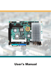
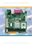
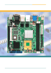
EmCORE-i6415VL
User's Manual
2A
1A
1B
2B
19A
29A
29B
19 B
3
7 3
6 3
5 3
4 3
3 3
2 3
1 3
0 2
9 2
8 2
7 2
6 2
5 2
4 2
3 2
2 2
1 2
0 1
9 1
8 1
7 1
6 1
5 1
4 1
3 1
2 1
1 1
0
9 8
7
6
5 4
3
2 1
UA
TA
UAA
T
RA
RA
PA
PA
NAA
M
NAA
M
LA
LA
KA
KA
JA
HA
JAA
H
845
GA
FAA
E
DA
CA
GA
BAA
A
Y
Y
W
2
1
5
1
6
W
V
U
V
U
T
T
R
R
P
N
P
N
M
M
L
K
m
PG
A
47
8B
1
FAA
E
DA
CA
BA
AA
L
K
J
H
H
G
F
G
F
E
E
D
D
C
B
C
B
A
A
3
2 2
7 3
6 3
5 3
4 3
3 3
2 3
1 3
0 9
8 2
7 2
6 2
5 2
4 2
3 2
2 2
1 2
0 1
9 1
8 1
7 1
6 1
5 1
4 1
3 1
2 1
1 1
0
J
9 8
7
6
5 4
3
2 1
1
1
2
1
30
29
0 3
9 2
3
8 2
7 2
6 2
5 2
4 2
3 2
ATi M7
2 2
1 2
0 2
9 1
8 1
7 1
6 1
5 1
4 1
3 1
2 1
1 1
0 1
9
8
7
2
6
5
1
4
3
2
1
1
A
B
C
D
E
F
G
H
J
K
L
M
N
P
R
T
U
V
W
Y
A
B
A
C
A
D
A
E
A
F
A
G
A
H
A
J
A
K
A
3
19
20
1
A
B
C
D
E
F
G
H
J
K
L
M
N
P
1
3
2
3 4
5
6
7 8
9 1 0 1 1 12 1 3 1 4
2
1
LAN
0
4
9
3
9
2
1
0
3
4
4
4
1
ICH4
11
1
1
1
2
12
1
1
9
1
10
2
19
10
2
3
3
1
4
MINI PCI
1
10
10
1
9
2
1
123
3
9
5
A1
A2
2
2
2
1
6
9
1
4
0
1
1
2
0
2
124
2
2
20
3
4
1
1
1
A61
A62
B1
B2
B61
B62
5.25" Intel Socket 478 Pentium 4 CPU
Single Board Computer with one DDR
DIMM socket, LCD/CRT, one Mini PCI,
one PCI slot, single LAN (10/100 or
1000 Mbps), 4 COM ports and 4 USB
2.0 ports
Copyright 2005
Copyright 2005 CONTEC CO., LTD. ALL RIGHTS RESERVED
INo part of this document may be copied or reproduced in any form by any means without prior written consent of CONTEC CO., LTD.
CONTEC CO., LTD. makes no commitment to update or keep current the information
contained in this document. The information in this document is subject to change
without notice.
All relevant issues have been considered in the preparation of this document. Should
you notice an omission or any questionable item in this document, please feel free to
notify CONTEC CO., LTD.
Regardless of the foregoing statement, CONTEC assumes no responsibility for any
errors that may appear in this document nor for results obtained by the user as a result of
using this product.
Trademarks
Intel, Celeron and Pentium are registered trademarks of Intel Corporation.
MS, Microsoft, Windows and Windows NT are trademarks of Microsoft Corporation.
Other brand and product names are trademarks of their respective holder.
All Other product names or trademarks are properties of their respective owners.
2
EmCORE-i6415VL User's Manual
Table of Contents
Specifications ................................................................................................................................ 5
Board Image ................................................................................................................................ 6
Board Layout ............................................................................................................................... 7
Board Dimension ......................................................................................................................... 8
Jumper/Connector Quick Reference .......................................................................................... 9
Jumper/Connector Quick Reference ........................................................................................ 10
CMOS Jumper Settings ............................................................................................................. 11
Watchdog Timer ........................................................................................................................ 12
Serial Port Selection (RS-232C/422A/485) ................................................................................. 16
LVDS LCD Power Selection ...................................................................................................... 17
TV-out Connector ....................................................................................................................... 17
VGA Connector .......................................................................................................................... 18
INV Connector ........................................................................................................................... 18
LVDS LCD Connector ................................................................................................................ 19
USB1 / USB2 Connector ............................................................................................................ 20
Audio Interface .......................................................................................................................... 20
FDD Connector .......................................................................................................................... 21
Enhanced IDE Connector .......................................................................................................... 22
Enhanced IDE Connector .......................................................................................................... 23
LPT1 ........................................................................................................................................... 24
COM 1-4 ...................................................................................................................................... 25
LAN Connector .......................................................................................................................... 26
CDIN Connector ......................................................................................................................... 26
ATX Power Connector .............................................................................................................. 27
ATX 12V Connector................................................................................................................... 28
Infrared (IR) Connector .............................................................................................................. 29
Keyboard & PS/2 Mouse ............................................................................................................ 29
Switches and Indicators ............................................................................................................ 30
CPU Fan Connector ................................................................................................................... 31
System Fan Connector .............................................................................................................. 31
EmCORE-i6415VL User's Manual
3
LAN LED Connector ................................................................................................................... 32
AWARD BIOS Setup ................................................................................................................... 33
Setup Items ...........................................................................................................................................................................
Standard CMOS Setup ..........................................................................................................................................................
IDE HDD AUTO DETECTION ..................................................................................................................................................
Advanced BIOS Features ....................................................................................................................................................
Advanced Chipset Features ................................................................................................................................................
Integrated Peripherals ..........................................................................................................................................................
Power Management Setup ...................................................................................................................................................
PnP/PCI Configurations .........................................................................................................................................................
PC Health Status ...................................................................................................................................................................
4
34
35
37
39
42
45
48
51
52
EmCORE-i6415VL User's Manual
Specifications
Item
Specification
CPU (Option)
Intel(R) Pentium(R) 4 Processor 2.4G - 3.06GHz (FSB 400M/533MHz), PGA
Cache
Built in CPU
Processor socket
Socket 478
Memory (Option)
One 184-pin DIMM socket, PC2100/2700 DDR SDRAM for up to 1GB
Chipset
Intel(R) 845GV+ICH4
BIOS
Award BIOS
Built in Intel(R) 845GV, Dual View
VGA
Analog RGB I/F x 1 (16 pin mini-box header connector x 1),
LVDS(18/24bit) I/F x 1 (30 pin-header connector x 1),
TV-out(NTSC/PAL) I/F x 1 (6 pin mini-box header connector x 1)
Keyboard/Mouse connector
One PS/2 Keyboard/Mouse connector (Bundled the 2 in 1 mini-DIN)
Serial I/F
16550 UART
40-pin header connector x 4 (RS-232C x 3, RS-232C/422A/485 x 1)
Baud rate: 50 - 115,200bps (programmable)
Parallel I/F
One high-speed parallel port, support SPP/EPP/ECP mode, One 20 pin-header
connector
On board expansion bus
One Mini PCI socket (Type III), One PCI bus
LAN Port
100BASE-TX/10BASE-T, Intel ICH4 integrated controller
One box-header 10-pin connector
IDE I/F
One EIDE port (support Ultra DMA100)
One box-header 44-pin connector (support Ultra DMA33)
Up to four IDE devices
SATA I/F
None
FDD I/F
3.5 inch 2mode I/F, One 20 pin-header connector
Compact Flash Slot
None
SSD Socket
None
USB Port
4ch USB 2.0 complaint ports, Two 10 pin-header connectors
IrDA
IrDA 1.1 complaint port, One 5 pin-header connector
RAID
None
Audio
AC97 CODEC, One box-header 10-pin connector for speaker out, line in, microphone
in.
Watchdog Timer
Software programmable 255 levels (1 - 255sec). Reset occurrence at the time of time
up.
General-purpose I/F
None
Hardware Monitor
Monitoring of the temperature of CPU and board, power supply voltage, and fan speed
RTC/CMOS
The backup time of the Lithium battery is over 6 years at 25°C.
The clock is accurate ±3 minutes/month at 25°C.
Power Management
Power management setup via BIOS
Bus specification / Size (mm)
None / 203(L) x 145(H)
DC Power Requirements
Power supply specifications (Max.)
+3.3V ±5%
+5VDC ±5%
+12VDC ±5%
+5VSB(Stand by) ±5%(Only when using the ATX power supply)
Pentium 4 2.8GHz + 512M DDR SDRAM
+3.3VDC 2.6A
+5VDC 1.8A
+12VDC 4.56A
+5VSB(Stand by) 0.25A(Only when using the ATX power supply)
Operating temperature /
Operating Humidity
0 - 60°C (Depends on the specification of CPU and heat sink.)
/10 - 90%RH (No condensation)
Storage temperature
-20 - 80°C
Floating dust particles
Not to be excessive
Corrosive gases
None
Weight
360g
Operating System Support
Windows XP Professional
Windows 2000 Professional
EmCORE-i6415VL User's Manual
5
Board Image
6
EmCORE-i6415VL User's Manual
Board Layout
DDR DIMM
2A
1A
1B
2B
19A
29A
29B
19B
3 3 3 3 3 3 3 3 2 2 2 2 2 2 2 2 2 2 1 1 1 1 1 1 1 1 1 1
7 6 5 4 3 2 1 0 9 8 7 6 5 4 3 2 1 0 9 8 7 6 5 4 3 2 1 0
m
P
G
A
4
7
8
B
9 8 7 6 5 4 3 2 1
UA
TA
UA
TA
RA
PA
NA
MA
LA
KA
RA
PA
NA
MA
LA
KA
JA
HA
GA
FA
EA
DA
JA
HA
GA
CA
BA
AA
Y
W
V
CA
BA
AA
Y
W
V
U
T
R
P
N
U
T
R
P
N
M
L
K
M
L
K
J
H
G
H
G
F
E
D
C
B
A
F
E
D
C
B
A
1
2
1
5
1
6
FA
EA
DA
3 3 3 3 3 3 3 3 2 2 2 2 2 2 2 2 2 2 1 1 1 1 1 1 1 1 1 1
7 6 5 4 3 2 1 0 9 8 7 6 5 4 3 2 1 0 9 8 7 6 5 4 3 2 1 0
J
VGA
9 8 7 6 5 4 3 2 1
1
1
2
1
30
29
2
1
03
92
3
82
72
TV-out
INV
JV9
62
52
42
32
22
12
LVDS
02
91
81
71
61
51
41
31
21
11
01
9
8
7
6
5
4
3
2
1
1
A
B
C
D
E
F
G
H
J
K
L
M
N
P
R
T
U
V
W
Y
A
A
B
A
C
A
D
A
E
A
F
A
G
A
H
A
J
A
K
A
3
19
20
SYSF1
1
CPUF1
3
1
2
3
4
5
6
7
8
9 10 11 12 13 14
A
B
C
D
E
F
G
H
J
K
L
M
N
P
LAN
0
4
9
3
3
44
4
1
11
RES
1
USB2
ATX
1
10
2
USB1
J1
3
19
9
0
2 1
10
2
IDE2
1
124
2
2
6
1
5
Mini PCI
123
10
LPT
4
PSON
20
1
9
1
IDE1
3
9
2
10
1
9
1
1
A61
A62
B61
B62
B1
B2
EmCORE-i6415VL User's Manual
2
2
1
LED2 AUDIO J4
2
4
0
1
A1
A2
LED1
LANLED
2
1
3
ATX1
1
34
12
1
J2
SIR
CDIN
1
0
9
2
ATX 12V
2
1
PCI Slot
1
HLED
FDD
KBMS
COM1 - COM4
7
Board Dimension
2A
1A
1B
2B
1 9A
2 9A
2 9B
1 9B
3 3 3 3 3 3 3 3 2 2 2 2 2 2 2 2 2 2 1 1 1 1 1 1 1 1
1
7 6 5 4 3 2 1 0 9 8 7 6 5 4 3 2 1 0 9 8 7 6 5 4 3 2 1
1 0
m
P
G
A
4
7
8
B
9 8 7 6 5 4 3 2 1
UA
TA
RA
PA
NA
MA
LA
KA
JA
HA
GA
FA
EA
DA
CA
BA
AA
Y
W
V
U
T
R
P
N
M
L
K
UA
TA
RA
PA
NA
MA
LA
KA
JA
HA
GA
FA
EA
DA
CA
BA
AA
Y
W
V
U
T
R
P
N
M
L
K
J
H
G
F
E
D
C
B
A
H
G
F
E
D
C
B
A
1
3 3 3 3 3 3 3 3 2 2 2 2 2 2 2 2 2 2 1 1 1 1 1 1 1 1
7 6 5 4 3 2 1 0 9 8 7 6 5 4 3 2 1 0 9 8 7 6 5 4 3 2 1 0
1
J
1
2
1
5
1
6
9 8 7 6 5 4 3 2 1
1
2
1
1
2
03
92
82
3
72
3
4
62
1
52
42
32
22
12
02
91
2
81
71
61
51
41
31
21
29
30
11
01
9
8
7
6
2
5
1
4
3
2
1
1
A
B
C
D
E
F
G
H
J
K
L
M
N
P
R
T
U
V
W
Y
A
A
B
A
C
A
D
A
E
A
F
A
G
A
H
A
J
A
K
A
3
19
20
1
23
22
21
20
19
18
1
17
16
15
14
13
3
12
2
3
4
5
6
7
8
9 10 11 12 13 14
A
B
C
D
E
F
G
H
J
K
L
M
N
P
04
11
93
1
0
9
10
2
2
1
9
3
8
7
2
3
6
4
4
3
4
5
4
4
4
1
1
3
1
1
2
2
1
1
1
A
B
C
D
E
F
G
H
J
K
L
M
N
P
R
T
U
V
W
1 2
4
Y AA AB AC
1
4
1
1
1
9
1
37 36
52
42
84
21 3
1
10
2
4
1
3
3
4
1
1
1
9
0
2
10
2
9
1
2
1
4
2
124
2
2
0
2
1
2
1
8
123
1
0
1
3
9
4
0
2
1
1
1
10
2
6
1
5
A1
A2
9
2
1
1
A61
A 62
B61
B1
B2
B 62
EmCORE-i6415VL User's Manual
Jumper/Connector Quick Reference
Jumpers
Lable
J1
J2
J4
JV9
Function
Clear CMOS
Watchdog Output
COM2 RS-232C / 422A / 485 Selection
LVDS LCD power select
EmCORE-i6415VL User's Manual
9
Jumper/Connector Quick Reference
Connectors
Lable
VGA
LVDS
IDE1
IDE2
USB1
USB2
AUDIO
SIR
KBMS
FDD
LAN
LPT1
COM1-4
LED1
LED2
CDIN
PSON
ATX1
ATX12V
TV
INV
LANLED
CPUF1
SYSF1
RES
HLED
10
Function
VGA Display Connector
LVDS LCD Connector
Primary IDE Connector
Secondary IDE Connector
USB Port 0,1
USB Port 2,3
Audio Interface Port
Infrared (IR) Connector
Keyboard and PS/2 Mouse
Floppy Drive Connector
10/100/1000 M LAN1 Connector
Parallel Port
RS-232C Serial Port (COM1 - 4)
power standby LED (Orange)
power-on/suspend LED (Green)
CD-ROM Audio Input
Power-on button
ATX power connector
ATX12V
TV-out connector
LCD Inverter connector
LAN LED connector
CPU Fan connector
System Fan connector
Reset Switch
IDE Activity LED
EmCORE-i6415VL User's Manual
CMOS Jumper Settings
CMOS Operation (J1)
Type : J1: onboard 3-pin header
If the EmCORE-i6415 refuses to boot due to inappropriate CMOS settings here is how
to proceed to clear (reset) the CMOS to its default values.
CMOS Setup (J1)
Normal Operation
Clear CMOS
default setting 1-2 ON
J1
1-2
2-3
2A
1A
1B
2B
1 9A
2 9A
2 9B
1 9B
3 3 3 3 3 3 3 3 2 2 2 2 2 2 2 2 2 2 1 1 1 1 1 1 1 1 1 1
7 6 5 4 3 2 1 0 9 8 7 6 5 4 3 2 1 0 9 8 7 6 5 4 3 2 1 0
9 8 7 6 5 4 3 2 1
UA
TA
RA
PA
NA
MA
LA
KA
JA
HA
GA
UA
TA
RA
PA
NA
MA
LA
KA
JA
HA
GA
FA
EA
DA
CA
BA
AA
Y
W
V
U
T
R
P
N
M
L
K
m
P
G
A
4
7
8
B
FAA
E
DA
CA
BA
AA
Y
W
V
U
T
R
P
N
M
L
K
J
H
G
F
E
D
C
B
A
H
G
F
E
D
C
B
A
3 3 3 3 3 3 3 3 2 2 2 2 2 2 2 2 2 2 1 1 1 1 1 1 1 1 1 1
7 6 5 4 3 2 1 0 9 8 7 6 5 4 3 2 1 0 9 8 7 6 5 4 3 2 1 0
J
1
2
15
1
6
9 8 7 6 5 4 3 2 1
1
1
1
2
03
92
3
82
72
62
52
42
32
22
12
02
91
81
71
61
51
41
31
29
30
21
11
01
9
8
7
2
6
5
1
4
3
2
1
1
A
B
C
D
E
F
G
H
J
K
L
M
N
P
R
T
U
V
W
Y
A
A
B
A
C
A
D
A
E
A
F
A
G
A
H
A
J
A
K
A
3
19
20
1
2 3
4
5
6
7
8
1
3
1
2
3
9 10 11 1 2 1 3 14
A
B
C
D
E
F
G
H
J
K
L
M
N
P
2
1
0
4
9
3
1
0
9
2
3
4
4
3
4
4
1
1
1
1
1
J1
2
12
1
1
1
3
9
1
10
2
19
10
2
3
1
0 9
2 1
4
1
2
6
2
1
0
2
5
123
0
1
3
9
2
4
0
2
1
1
2
2
1
10
A1
A2
1
9
B1
B2
EmCORE-i6415VL User's Manual
124
1
1
A61
A62
B61
B62
11
Watchdog Timer
Watchdog Output (J2)
The onboard watchdog timer can be disable by jumper setting or enable for either reboot
by system RESET or invoking an NMI (Non-Maskable Interrupt)
Even if enabled by jumper setting upon boot the watchdog timer is always inactive. To
initialize or refresh the watchdog timer writing of port 44h is sufficient. To disable the
watchdog time read port 44h.
Status
Enable/refresh the Watchdog Timer
Disable the Watchdog Timer.
Action
I/O Write 044h
I/O Read 044h
After the watchdog timer has been initialized by writing port 044h, it has to be strobed at
preconfigured intervals to keep it from issuing a RESET or NMI.
The watchdog timer timeout intervals are set by software programming.
Mode Setting
Watchdog Mode
Enabled for System Reset
default setting
J2
2-3
2A
1A
1B
2B
1 9A
2 9A
2 9B
1 9B
3 3 3 3 3 3 3 3 2 2 2 2 2 2 2 2 2 2 1 1 1 1 1 1 1 1 1 1
7 6 5 4 3 2 1 0 9 8 7 6 5 4 3 2 1 0 9 8 7 6 5 4 3 2 1 0
9 8 7 6 5 4 3 2 1
UA
TA
RA
PA
NA
MA
LA
KA
JA
HA
GA
UA
TA
RA
PA
NA
MA
LA
KA
JA
HA
GA
FA
EA
DA
CA
BA
AA
Y
W
V
U
T
R
P
N
M
L
K
mP
G
4A
78
B
FAA
E
DA
CA
BA
AA
Y
W
V
U
T
R
P
N
M
L
K
J
H
G
F
E
D
C
B
A
H
G
F
E
D
C
B
A
3 3 3 3 3 3 3 3 2 2 2 2 2 2 2 2 2 2 1 1 1 1 1 1 1 1 1 1
7 6 5 4 3 2 1 0 9 8 7 6 5 4 3 2 1 0 9 8 7 6 5 4 3 2 1 0
J
1
2
1
5
1
6
9 8 7 6 5 4 3 2 1
1
1
1
2
03
92
3
82
72
62
52
42
32
22
12
02
91
81
71
61
51
41
31
21
30
29
2
1
11
01
9
8
7
6
5
4
3
2
1
1
A
B
C
D
E
F
G
H
J
K
L
M
N
P
R
T
U
V
W
Y
A
A
6
7
B
A
C
A
D
A
E
A
F
A
G
A
H
A
J
A
K
A
3
19
20
1
1
3
1
2
3
2
3
4
5
8 9 1 0 1 1 1 2 13 14
A
B
C
D
E
F
G
H
J
K
L
M
N
P
2
1
04
93
1
0
9
2
3
4
4
3
4
4
1
1
1
1
1
2
12
1
1
1
3
9
1
10
2
3
J2
1
19
9
0 1
2
10
2
4
1
2
Timeout Values
0
2
2
6
1
5
124
123
0
1
3
9
2
4
0
2
1
1
2
10
A1
A2
1
2
1
9
B1
B2
1
1
A 61
A6 2
B 61
B6 2
Timout values are programmed. The watchdog timer supports 254 steps.
use the table on the next page to find the hexidecimal value that needs to be passed on
to get the correct timer interval. Look subsequntly at the program
12
EmCORE-i6415VL User's Manual
example how to pass the value to the watchdog timer.
Timeout Table
Level
1
4
7
10
13
16
19
22
25
28
31
34
37
40
43
46
49
52
55
58
61
64
67
70
73
76
79
82
85
88
91
94
97
100
103
106
109
112
115
118
121
Value
1
4
7
A
D
10
13
16
19
1C
1F
22
25
28
2B
2E
31
34
37
3A
3D
40
43
46
49
4C
4F
52
55
58
5B
5E
61
64
67
6A
6D
70
73
76
79
Seconds
1
4
7
10
13
16
19
22
25
28
31
34
37
40
43
46
49
52
55
58
61
64
67
70
73
76
79
82
85
88
91
94
97
100
103
106
109
112
115
118
121
Level
2
5
8
11
14
17
20
23
26
29
32
35
38
41
44
47
50
53
56
59
62
65
68
71
74
77
80
83
86
89
92
95
98
101
104
107
110
113
116
119
122
Value
2
5
8
B
E
11
14
17
1A
1D
20
23
26
29
2C
2F
32
35
38
3B
3E
41
44
47
4A
4D
50
53
56
59
5C
5F
62
65
68
6B
6E
71
74
77
7A
EmCORE-i6415VL User's Manual
Seconds
2
5
8
11
14
17
20
23
26
29
32
35
38
41
44
47
50
53
56
59
62
65
68
71
74
77
80
83
86
89
92
95
98
101
104
107
110
113
116
119
122
Level
3
6
9
12
15
18
21
24
27
30
33
36
39
42
45
48
51
54
57
60
63
66
69
72
75
78
81
84
87
90
93
96
99
102
105
108
111
114
117
120
123
Value
3
6
9
C
F
12
15
18
1B
1E
21
24
27
2A
2D
30
33
36
39
3C
3F
42
45
48
4B
4E
51
54
57
5A
5D
60
63
66
69
6C
6F
72
75
78
7B
Seconds
3
6
9
12
15
18
21
24
27
30
33
36
39
42
45
48
51
54
57
60
63
66
69
72
75
78
81
84
87
90
93
96
99
102
105
108
111
114
117
120
123
13
Timeout Table
Level
124
127
130
133
136
139
142
145
148
151
154
157
160
163
166
169
172
175
178
181
184
187
190
193
196
199
202
205
208
211
214
217
220
223
226
229
232
235
238
241
244
247
250
253
14
Value
7C
7F
82
85
88
8B
8E
91
94
97
9A
9D
A0
A3
A6
A9
AC
AF
B2
B5
B8
BB
BE
C1
C4
C7
CA
CD
D0
D3
D6
D9
DC
DF
E2
E5
E8
EB
EE
F1
F4
F7
FA
FD
Seconds
124
127
130
133
136
139
142
145
148
151
154
157
160
163
166
169
172
175
178
181
184
187
190
193
196
199
202
205
208
211
214
217
220
223
226
229
232
235
238
241
244
247
250
253
Level
125
128
131
134
137
140
143
146
149
152
155
158
161
164
167
170
173
176
179
182
185
188
191
194
197
200
203
206
209
212
215
218
221
224
227
230
233
236
239
242
245
248
251
Value
7D
80
83
86
89
8C
8F
92
95
98
9B
9E
A1
A4
A7
AA
AD
B0
B3
B6
B9
BC
BF
C2
C5
C8
CB
CE
D1
D4
D7
DA
DD
E0
E3
E6
E9
EC
EF
F2
F5
F8
FB
Seconds
125
128
131
134
137
140
143
146
149
152
155
158
161
164
167
170
173
176
179
182
185
188
191
194
197
200
203
206
209
212
215
218
221
224
227
230
233
236
239
242
245
248
251
Level
126
129
132
135
138
141
144
147
150
153
156
159
162
165
168
171
174
177
180
183
186
189
192
195
198
201
204
207
210
213
216
219
222
225
228
231
234
237
240
243
246
249
252
Value
7E
81
84
87
8A
8D
90
93
96
99
9C
9F
A2
A5
A8
AB
AE
B1
B4
B7
BA
BD
C0
C3
C6
C9
CC
CF
D2
D5
D8
DB
DE
E1
E4
E7
EA
ED
F0
F3
F6
F9
FC
Seconds
126
129
132
135
138
141
144
147
150
153
156
159
162
165
168
171
174
177
180
183
186
189
192
195
198
201
204
207
210
213
216
219
222
225
228
231
234
237
240
243
246
249
252
EmCORE-i6415VL User's Manual
Programming Example
The following program is an examples of how to enable,
disable and refresh the Watchdog timer:
WDT_EN_RF
equ
044h
WDT_DIS
equ
044h
WT_Enable push AX
; Save AX,DX
push DX
mov DX,WDT_EN_RF
; Enable Timer
mov AX,INTERVAL ; Set Timeout Value
out DX,AX
pop DX
; Restore DX,AX
pop AX
ret
WT_Refresh push AX
; Save AX,DX
push DX
mov DX,WDT_EN_RF
; Refresh Timer
mov AX,INTERVAL ; Set Timout Value
out DX,AX
pop DX
; Restore DX,AX
pop AX
ret
WT_Disable push AX
; Save AX,DX
push DX
mov DX,WDT_DIS ; Disable Timer
in AX,DX
pop DX
; Restore DX,AX
pop AX
ret
WT_Disable push AX
; save AX,DX
push DX
mov DX,WDT_DIS ; Disable Timer
in AX,DX
pop DX
; restore DX,AX
pop AX
ret
EmCORE-i6415VL User's Manual
15
Serial Port Selection (RS-232C/422A/485)
RS-232C/422A/485 Mode select (J4)
Type : J4: onboard 6-pin(2*3) header
RS-422A/485 Mode on COM2
The onboard COM2 port can be configured to operate in RS-422A or RS-485 modes.
RS-422A modes differ in the way RX/TX is being handled. Jumper J4 switches between RS-232C or RS-422A/485 mode. All of the RS-232C/422A/485 modes are available on COM2.
J4 Selection
RS-232C
RS-422A
RS-485
1-2
ON
OFF
OFF
3-4
OFF
ON
OFF
5-6
OFF
OFF
ON
default setting RS-232C
COM2
Pin :
11 :
12 :
18 :
19 :
RS-232C
DCD
RXD
CTS
RI
J4: 3-4
RS-422A
Tx+
TxRx+
Rx-
RS-485
data+
datax
x
COM1 - 4
1
2
RXD
J4: 5-6
RTS#
TXD
39
40
2A
1A
1B
2B
19A
29A
29B
19B
3 3 3 3 3 3 3 3 2 2 2 2 2 2 2 2 2 2 1 1 1 1 1 1 1 1 1 1
7 6 5 4 3 2 1 0 9 8 7 6 5 4 3 2 1 0 9 8 7 6 5 4 3 2 1 0
9 8 7 6 5 4 3 2 1
UA
TA
RA
PA
NA
MA
LA
KA
JA
HA
GA
UA
TA
RA
PA
NA
MA
LA
KA
JA
HA
GA
FA
EA
DA
CA
BA
AA
Y
W
V
U
T
R
P
N
M
L
K
J
H
G
F
E
D
C
B
A
mP
G
47A
8B
FAA
E
DA
CA
BA
AA
Y
W
V
U
T
R
P
N
M
L
K
H
G
F
E
D
C
B
A
3 3 3 3 3 3 3 3 2 2 2 2 2 2 2 2 2 2 1 1 1 1 1 1 1 1 1 1
7 6 5 4 3 2 1 0 9 8 7 6 5 4 3 2 1 0 9 8 7 6 5 4 3 2 1 0
J
1
2
15
1
6
9 8 7 6 5 4 3 2 1
1
1
1
2
03
92
3
82
72
62
52
42
32
22
12
02
91
81
71
61
51
41
31
21
30
29
2
1
11
01
9
8
7
6
5
4
3
2
1
1
A
B
C
D
E
F
G
H
J
K
L
M
N
P
R
T
U
V
W
Y
A
A
B
A
C
A
D
A
E
A
F
A
G
A
H
A
J
A
K
A
3
19
20
1
2
3 4
5 6
7
8 9 10 11 1 2 13 1 4
A
B
C
D
E
F
G
H
J
K
L
M
N
P
1
3
2
1
0
4
9
3
1
0
9
2
3
4
4
4
1
11
1
1
3
4
2
12
1
1
1
3
9
1
10
2
3
531
1
19
9
20 1
10
2
4
1
2
6
2
1
20
124
5
123
10
3
9
10
1
9
B1
B2
2
2
1
A1
A2
2
4
0
1
2
1
1
1
A61
A62
B61
B62
642
16
EmCORE-i6415VL User's Manual
LVDS LCD Power Selection
Type : JV9: onboard 3-pin header
The voltage of LCD panel could be selected by JV9 in 5V or 3.3V.
Mode
3.3V
5V
JV9
1-2
2-3
default setting
3.3V
2A
1A
1B
2B
1 9A
2 9A
2 9B
1 9B
3 3 3 3 3 3 3 3 2 2 2 2 2 2 2 2 2 2 1 1 1 1 1 1 1 1 1 1
7 6 5 4 3 2 1 0 9 8 7 6 5 4 3 2 1 0 9 8 7 6 5 4 3 2 1 0
mP
GA
4
78
B
1
9 8 7 6 5 4 3 2 1
UA
TA
RA
PA
NA
MA
LA
KA
JA
HA
GA
UA
TA
RA
PA
NA
MA
LA
KA
JA
HA
GA
FA
EA
DA
CA
BA
AA
Y
W
V
U
T
R
P
N
M
L
K
FAA
E
DA
CA
BA
AA
Y
W
V
U
T
R
P
N
M
L
K
J
H
G
F
E
D
C
B
A
H
G
F
E
D
C
B
A
3 3 3 3 3 3 3 3 2 2 2 2 2 2 2 2 2 2 1 1 1 1 1 1 1 1 1 1
7 6 5 4 3 2 1 0 9 8 7 6 5 4 3 2 1 0 9 8 7 6 5 4 3 2 1 0
J
1
2
1
5
1
6
6
9 8 7 6 5 4 3 2 1
1
1
1
2
03
92
3
82
72
62
52
42
32
TV-OUT
22
12
02
91
81
71
61
51
41
31
29
30
21
11
01
9
8
7
2
6
5
1
4
3
2
1
1
A
B
C
D
E
F
G
H
J
K
L
M
N
P
R
T
U
V
W
Y
A
A
B
A
C
A
D
A
E
A
F
A
G
A
H
A
J
A
K
A
3
19
20
1
2
3
4
5
6
7
8 9 1 0 1 1 1 2 13 14
A
B
C
D
E
F
G
H
J
K
L
M
N
P
1
3
2
1
40
1
2
3
39
1
0
9
2
3
4
4
3
4
4
1
1
1
1
1
2
12
1
1
1
3
9
1
10
2
3
J V9
1
19
0 9
2 1
10
2
4
1
2
6
2
1
20
124
5
123
0
1
3
9
2
4
0
2
1
1
2
10
2
1
A1
A2
1
9
B1
B2
1
1
A 61
A6 2
B 61
B6 2
TV-out Connector
Connector : TV Connector
Type: Onboard 6-pin wafer
PIN Description
1
2
3
4
5
6
Composite Video
GND
S-Video Y
GND
S-Video C
GND
EmCORE-i6415VL User's Manual
17
VGA Connector
Connector : VGA Connector
Type: Onboard 16-pin mini boxheader
Pin
Description
Pin Description
Pin
Description
1
2
3
4
5
16
RED
GREEN
BLUE
NC
GND
NC
6
7
8
9
10
11
12
13
14
15
NC
VDDAT
HSYNC
VSYNC
VDCLK
GND
GND
GND
Vcc
GND
2A
1A
1B
2B
1 9A
2 9A
2 9B
1 9B
3 3 3 3 3 3 3 3 2 2 2 2 2 2 2 2 2 2 1 1 1 1 1 1 1 1 1 1
7 6 5 4 3 2 1 0 9 8 7 6 5 4 3 2 1 0 9 8 7 6 5 4 3 2 1 0
mP
G
4A
78
B
1
9 8 7 6 5 4 3 2 1
UA
TA
RA
PA
NA
MA
LA
KA
JA
HA
GA
UA
TA
RA
PA
NA
MA
LA
KA
JA
HA
GA
FA
EA
DA
CA
BA
AA
Y
W
V
U
T
R
P
N
M
L
K
FAA
E
DA
CA
BA
AA
Y
W
V
U
T
R
P
N
M
L
K
J
H
G
F
E
D
C
B
A
H
G
F
E
D
C
B
A
3 3 3 3 3 3 3 3 2 2 2 2 2 2 2 2 2 2 1 1 1 1 1 1 1 1 1 1
7 6 5 4 3 2 1 0 9 8 7 6 5 4 3 2 1 0 9 8 7 6 5 4 3 2 1 0
J
1
2
1
5
1
6
2
9 8 7 6 5 4 3 2 1
VGA
1
1
1
2
03
92
3
82
72
62
52
42
32
22
12
02
91
81
71
61
51
41
31
21
30
29
2
1
11
01
9
8
7
6
5
4
3
2
1
1
A
B
C
D
E
F
G
H
J
K
L
M
N
P
R
T
U
V
W
Y
A
A
6
7
B
A
C
A
D
A
E
A
F
A
G
A
H
A
J
A
K
A
3
19
20
1
2
3
4
5
8 9 1 0 1 1 1 2 13 14
A
B
C
D
E
F
G
H
J
K
L
M
N
P
1
3
2
1
04
1
2
3
4
5
93
1
0
9
2
3
4
4
3
4
4
1
1
1
1
1
2
12
1
1
1
3
9
1
10
2
19
10
2
3
1
0 9
2 1
4
INV
1
124
2
0
2
2
6
1
5
123
0
1
3
9
2
4
0
2
1
1
2
10
2
1
A1
A2
1
1
1
A 61
A6 2
9
B 61
B6 2
B1
B2
INV Connector
Connector : LCD Inverter connector
Type : Onboard 5-pin wafer
Pin
1
3
5
18
Description
+12 V
on/off
GND
Pin
2
4
Description
GND
brightness control
EmCORE-i6415VL User's Manual
LVDS LCD Connector
Connector : LVDS LCD Connector
Type : onboard 30-pin header
Pin
1
3
5
7
9
11
13
15
17
19
21
23
25
27
29
Signal
VDD
TX1CLK+
TX1CLKGND
TX1D0+
TX1D0GND
TX1D1+
TX1D1GND
TX1D2+
TX1D2GND
TX1D3+
TX1D3-
Pin
2
4
6
8
10
12
14
16
18
20
22
24
26
28
30
Signal
VDD
TX2CLK+
TX2CLKGND
TX2D0+
TX2D0GND
TX2D1+
TX2D1GND
TX2D2+
TX2D2GND
TX2D3+
TX2D3-
2A
1A
1B
2B
1 9A
2 9A
2 9B
1 9B
3 3 3 3 3 3 3 3 2 2 2 2 2 2 2 2 2 2 1 1 1 1 1 1 1 1 1 1
7 6 5 4 3 2 1 0 9 8 7 6 5 4 3 2 1 0 9 8 7 6 5 4 3 2 1 0
9 8 7 6 5 4 3 2 1
UA
TA
RA
PA
NA
MA
LA
KA
JA
HA
GA
UA
TA
RA
PA
NA
MA
LA
KA
JA
HA
GA
FA
EA
DA
CA
BA
AA
Y
W
V
U
T
R
P
N
M
L
K
mP
G
4A
78
B
FAA
E
DA
CA
BA
AA
Y
W
V
U
T
R
P
N
M
L
K
J
H
G
F
E
D
C
B
A
H
G
F
E
D
C
B
A
3 3 3 3 3 3 3 3 2 2 2 2 2 2 2 2 2 2 1 1 1 1 1 1 1 1 1 1
7 6 5 4 3 2 1 0 9 8 7 6 5 4 3 2 1 0 9 8 7 6 5 4 3 2 1 0
J
1
2
1
5
1
6
2
1
30
29
9 8 7 6 5 4 3 2 1
1
1
1
2
03
92
3
82
72
62
52
42
32
22
12
02
91
81
71
61
51
41
31
21
30
29
2
1
11
01
9
8
7
6
5
4
3
2
1
1
A
B
C
D
E
F
G
H
J
K
L
M
N
P
R
T
U
V
W
Y
A
A
B
A
C
A
D
A
E
A
F
A
G
A
H
A
J
A
K
A
3
19
20
1
2 3
4
5
6
7
8
9 10 11 1 2 1 3 14
A
B
C
D
E
F
G
H
J
K
L
M
N
P
1
3
2
1
04
93
1
0
9
2
3
4
4
3
4
4
1
1
1
1
1
2
12
1
1
1
3
9
1
10
2
19
10
2
3
1
0 9
2 1
4
1
2
20
2
6
1
5
124
123
0
1
3
9
2
4
0
2
1
2
A1
A2
1
2
1
10
9
B1
B2
EmCORE-i6415VL User's Manual
A61
A62
1
1
1
B61
B62
19
USB1 / USB2 Connector
Connector : USB connector
Type:onboard Two 9-pin box headers
Pin
1
3
5
7
9
Description
VCC
DATADATA+
GND
GND
Pin
2
4
6
8
Description
VCC
DATADATA+
GND
Audio Interface
Connector : Audio
Type : Onboard 10-pin header
Pin
1
3
5
7
9
Description
LINE IN LEFT
GND
MIC
GND
SPEAKER LEFT
Pin
2
4
6
8
10
Description
LINE IN RIGHT
GND
NC
GND
SPEAKER RIGHT
2A
1A
1B
2B
1 9A
2 9A
2 9B
1 9B
3 3 3 3 3 3 3 3 2 2 2 2 2 2 2 2 2 2 1 1 1 1 1 1 1 1 1 1
7 6 5 4 3 2 1 0 9 8 7 6 5 4 3 2 1 0 9 8 7 6 5 4 3 2 1 0
9 8 7 6 5 4 3 2 1
UA
TA
RA
PA
NA
MA
LA
KA
JA
HA
GA
UA
TA
RA
PA
NA
MA
LA
KA
JA
HA
GA
FA
EA
DA
CA
BA
AA
Y
W
V
U
T
R
P
N
M
L
K
m
P
G
A
4
7
8
B
FAA
E
DA
CA
BA
AA
Y
W
V
U
T
R
P
N
M
L
K
J
H
G
F
E
D
C
B
A
H
G
F
E
D
C
B
A
3 3 3 3 3 3 3 3 2 2 2 2 2 2 2 2 2 2 1 1 1 1 1 1 1 1 1 1
7 6 5 4 3 2 1 0 9 8 7 6 5 4 3 2 1 0 9 8 7 6 5 4 3 2 1 0
J
1
2
15
1
6
9 8 7 6 5 4 3 2 1
1
1
1
2
03
92
3
82
72
62
52
42
32
22
12
02
91
81
71
61
51
41
31
21
30
29
2
1
11
01
9
8
7
6
5
4
3
2
1
1
A
B
C
D
E
F
G
H
J
K
L
M
N
P
R
T
U
V
W
Y
A
A
B
A
C
A
D
A
E
A
F
A
G
A
H
A
J
A
K
A
3
19
20
1
2 3
4
5
6
7
8
9 10 11 1 2 1 3 14
A
B
C
D
E
F
G
H
J
K
L
M
N
P
1
3
2
1
0
4
1
0
9
2
4
4
3
4
4
1
1
1
2
4
6
8
9
3
3
1
1
1
3
5
7
9
2
USB
12
1
1
1
3
9
1
10
2
19
10
2
3
1
0 9
2 1
4
1
124
2
0
2
2
6
1
5
3
9
123
0
1
2
4
0
2
1
1
2
2
1
10
A1
A2
1
1
1
A61
A62
9
B61
B62
B1
B2
10
9
2
1
Audio
20
EmCORE-i6415VL User's Manual
FDD Connector
Connector : FDD Connector
Type : Onboard 20-pin header
Pin
1
3
5
7
9
11
13
15
17
19
Description
GND
GND
GND
#Write data
#Write gate
#Track 0
#Write protect
#Read data
#Head select
#Disk change
Pin
2
4
6
8
10
12
14
16
18
20
Description
Drive density select 0
NC (Key)
Drive density select 1
#Index
#Motor enable A
#Driver select B
#Driver select A
#Motor enable B
#Direction
#Step
2A
1A
1B
2B
1 9A
2 9A
2 9B
1 9B
3 3 3 3 3 3 3 3 2 2 2 2 2 2 2 2 2 2 1 1 1 1 1 1 1 1 1 1
7 6 5 4 3 2 1 0 9 8 7 6 5 4 3 2 1 0 9 8 7 6 5 4 3 2 1 0
9 8 7 6 5 4 3 2 1
UA
TA
RA
PA
NA
MA
LA
KA
JA
HA
GA
UA
TA
RA
PA
NA
MA
LA
KA
JA
HA
GA
FA
EA
DA
CA
BA
AA
Y
W
V
U
T
R
P
N
M
L
K
mP
G
4A
78
B
FAA
E
DA
CA
BA
AA
Y
W
V
U
T
R
P
N
M
L
K
J
H
G
F
E
D
C
B
A
H
G
F
E
D
C
B
A
3 3 3 3 3 3 3 3 2 2 2 2 2 2 2 2 2 2 1 1 1 1 1 1 1 1 1 1
7 6 5 4 3 2 1 0 9 8 7 6 5 4 3 2 1 0 9 8 7 6 5 4 3 2 1 0
J
1
2
1
5
1
6
9 8 7 6 5 4 3 2 1
1
1
1
2
03
92
3
82
72
62
52
42
32
22
12
02
91
81
71
61
51
41
31
21
30
29
2
1
11
01
9
8
7
6
5
4
3
2
1
1
A
B
C
D
E
F
G
H
J
K
L
M
N
P
R
T
U
V
W
Y
A
A
B
A
C
A
D
A
E
A
F
A
G
A
H
A
J
A
K
A
3
19
20
1
2 3
4
5
6
7
8
9 10 11 1 2 1 3 14
A
B
C
D
E
F
G
H
J
K
L
M
N
P
1
3
2
1
04
93
1
0
9
2
3
4
4
3
4
4
1
1
1
1
1
2
12
1
1
1
3
9
1
10
2
3
1
19
9
0 1
2
10
2
4
1
2
02
2
6
1
5
124
123
0
1
3
9
20
19
2
1
2
4
0
2
1
1
2
A1
A2
1
2
1
10
9
B1
B2
EmCORE-i6415VL User's Manual
1
1
A61
A62
B61
B62
21
Enhanced IDE Connector
Connector : IDE1
Type : Two onboard 40-pin box headers, primary and secondary IDE
Pin
1
3
5
7
9
11
13
15
17
19
21
23
25
27
29
31
33
35
37
39
Description
#RESET
D7
D6
D5
D4
D3
D2
D1
D0
GND
REQ
#IOW
#IOR
#IORDY
#DACK
IRQ
ADDR1
ADDR0
#CS1
#ACT
Pin
2
4
6
8
10
12
14
16
18
20
22
24
26
28
30
32
34
36
38
40
Description
GND
D8
D9
D10
D11
D12
D13
D14
D15
NC/(Vcc)
GND
GND
GND
IDESEL
GND
NC (-IOCS16)
CBLID
ADDR2
#CS3(#HD SELET1)
GND
2A
1A
1B
2B
1 9A
2 9A
2 9B
1 9B
3 3 3 3 3 3 3 3 2 2 2 2 2 2 2 2 2 2 1 1 1 1 1 1 1 1 1 1
7 6 5 4 3 2 1 0 9 8 7 6 5 4 3 2 1 0 9 8 7 6 5 4 3 2 1 0
9 8 7 6 5 4 3 2 1
UA
TA
RA
PA
NA
MA
LA
KA
JA
HA
GA
UA
TA
RA
PA
NA
MA
LA
KA
JA
HA
GA
FA
EA
DA
CA
BA
AA
Y
W
V
U
T
R
P
N
M
L
K
mP
GA
4
78
B
FAA
E
DA
CA
BA
AA
Y
W
V
U
T
R
P
N
M
L
K
J
H
G
F
E
D
C
B
A
H
G
F
E
D
C
B
A
3 3 3 3 3 3 3 3 2 2 2 2 2 2 2 2 2 2 1 1 1 1 1 1 1 1 1 1
7 6 5 4 3 2 1 0 9 8 7 6 5 4 3 2 1 0 9 8 7 6 5 4 3 2 1 0
J
1
2
1
5
1
6
9 8 7 6 5 4 3 2 1
1
1
1
2
03
92
3
82
72
62
52
42
32
22
12
02
91
81
71
61
51
41
31
21
30
29
2
1
11
01
9
8
7
6
5
4
3
2
1
1
A
B
C
D
E
F
G
H
J
K
L
M
N
P
R
T
U
V
W
Y
A
A
B
A
C
A
D
A
E
A
F
A
G
A
H
A
J
A
K
A
3
19
20
1
2 3
4
5
6
7
8
9 10 11 1 2 1 3 14
A
B
C
D
E
F
G
H
J
K
L
M
N
P
1
3
2
1
40
39
1
0
9
2
3
4
4
3
4
4
1
1
1
1
1
2
12
1
2
1
1
3
9
1
10
2
1
3
1
19
0 9
2 1
10
2
4
1
2
6
2
1
0
2
5
123
0
1
3
9
2
4
0
2
1
1
2
2
1
10
A1
A2
1
9
B1
B2
22
124
1
1
A61
A62
B61
B62
EmCORE-i6415VL User's Manual
Enhanced IDE Connector
Connector : IDE2
Type : One onboard 44-pin box headers, primary IDE
Pin
1
3
5
7
9
11
13
15
17
19
21
23
25
27
29
31
33
35
37
39
41
43
Description
#RESET
D7
D6
D5
D4
D3
D2
D1
D0
GND
REQ
#IOW
#IOR
#IORDY
#DACK
IRQ
ADDR1
ADDR0
#CS0
#ACT
Vcc
GND
Pin
2
4
6
8
10
12
14
16
18
20
22
24
26
28
30
32
34
36
38
40
42
44
Description
GND
D8
D9
D10
D11
D12
D13
D14
D15
NC
GND
GND
GND
IDESEL
GND
NC (-IOCS16)
CBLID
ADDR2
#CS1(#HD SELET1)
GND
Vcc
NC
2A
1A
1B
2B
1 9A
2 9A
2 9B
1 9B
3 3 3 3 3 3 3 3 2 2 2 2 2 2 2 2 2 2 1 1 1 1 1 1 1 1 1 1
7 6 5 4 3 2 1 0 9 8 7 6 5 4 3 2 1 0 9 8 7 6 5 4 3 2 1 0
9 8 7 6 5 4 3 2 1
UA
TA
RA
PA
NA
MA
LA
KA
JA
HA
GA
UA
TA
RA
PA
NA
MA
LA
KA
JA
HA
GA
FA
EA
DA
CA
BA
AA
Y
W
V
U
T
R
P
N
M
L
K
mP
G
4A
78
B
FAA
E
DA
CA
BA
AA
Y
W
V
U
T
R
P
N
M
L
K
J
H
G
F
E
D
C
B
A
H
G
F
E
D
C
B
A
3 3 3 3 3 3 3 3 2 2 2 2 2 2 2 2 2 2 1 1 1 1 1 1 1 1 1 1
7 6 5 4 3 2 1 0 9 8 7 6 5 4 3 2 1 0 9 8 7 6 5 4 3 2 1 0
J
1
2
1
5
1
6
9 8 7 6 5 4 3 2 1
1
1
1
2
03
92
3
82
72
62
52
42
32
22
12
02
91
81
71
61
51
41
31
21
30
29
2
1
11
01
9
8
7
6
5
4
3
2
1
1
A
B
C
D
E
F
G
H
J
K
L
M
N
P
R
T
U
V
W
Y
A
A
6
7
B
A
C
A
D
A
E
A
F
A
G
A
H
A
J
A
K
A
3
19
20
1
2
3
4
5
8 9 1 0 1 1 1 2 13 14
A
B
C
D
E
F
G
H
J
K
L
M
N
P
1
3
2
1
40
39
1
0
9
2
3
4
4
2
1
3
4
4
1
1
1
1
1
2
12
1
1
1
3
9
1
10
2
3
1
19
0 9
2 1
10
2
4
1
2
20
2
6
1
5
124
123
0
1
3
9
2
4
0
2
1
1
2
10
A1
A2
1
2
1
9
B1
B2
EmCORE-i6415VL User's Manual
1
1
A 61
A6 2
B 61
B6 2
23
LPT1
Connector : LPT Connector
Type : Onboard 20-pin header
Pin
1
3
5
7
9
11
13
15
17
19
Description
#STROBE
Data 0
1
2
3
4
5
6
7
#Acknowledge
Pin
2
4
6
8
10
12
14
16
18
20
Description
#Auto feed
#Error
#Initialize
#Select Input
GND
GND
NC (KEY)
Busy
Paper Empty
Select
2A
1A
1B
2B
1 9A
2 9A
2 9B
1 9B
3 3 3 3 3 3 3 3 2 2 2 2 2 2 2 2 2 2 1 1 1 1 1 1 1 1 1 1
7 6 5 4 3 2 1 0 9 8 7 6 5 4 3 2 1 0 9 8 7 6 5 4 3 2 1 0
9 8 7 6 5 4 3 2 1
UA
TA
RA
PA
NA
MA
LA
KA
JA
HA
GA
UA
TA
RA
PA
NA
MA
LA
KA
JA
HA
GA
FA
EA
DA
CA
BA
AA
Y
W
V
U
T
R
P
N
M
L
K
m
P
G
A
4
7
8
B
FAA
E
DA
CA
BA
AA
Y
W
V
U
T
R
P
N
M
L
K
J
H
G
F
E
D
C
B
A
H
G
F
E
D
C
B
A
3 3 3 3 3 3 3 3 2 2 2 2 2 2 2 2 2 2 1 1 1 1 1 1 1 1 1 1
7 6 5 4 3 2 1 0 9 8 7 6 5 4 3 2 1 0 9 8 7 6 5 4 3 2 1 0
J
1
2
15
1
6
9 8 7 6 5 4 3 2 1
1
1
1
2
03
92
3
82
72
62
52
42
32
22
12
02
91
81
71
61
51
41
31
29
30
21
11
01
9
8
7
2
6
5
1
4
3
2
1
1
A
B
C
D
E
F
G
H
J
K
L
M
N
P
R
T
U
V
W
Y
A
A
B
A
C
A
D
A
E
A
F
A
G
A
H
A
J
A
K
A
3
19
20
1
2 3
4
5
6
7
8
9 10 11 1 2 1 3 14
A
B
C
D
E
F
G
H
J
K
L
M
N
P
1
3
2
1
0
4
9
3
1
0
9
2
3
4
4
3
4
4
1
1
1
1
1
2
12
1
1
1
3
9
1
1
2
19
20
10
2
3
1
19
0 9
2 1
10
2
4
1
2
0
2
2
6
1
5
123
0
1
3
9
2
4
0
2
1
1
2
1
2
1
10
A1
A2
9
B1
B2
24
124
1
1
A61
A62
B61
B62
EmCORE-i6415VL User's Manual
COM 1 - 4
Connector : RS-232C/422A/485 serial connector
Type : Onboard 40-pin min-box header
Pin
1
3
5
7
9
11
13
15
17
19
21
23
25
27
29
31
33
35
37
39
COM1
COM2
COM3
COM4
Description
Pin
DCD1
2
TXD1
4
GND
6
RTS1
8
RI1
10
DCD2(RS-422A TX+ / RS-485 data+) 12
TXD2
14
GND
16
RTS2
18
RI2(RS-422A RX-)
20
DCD3
22
TXD3
24
GND
26
RTS2
28
RI2
30
DCD4
32
TXD4
34
GND
36
RTS4
38
RI
40
Description
RXD1
DTR1
DSR1
CTS1
N.C.
RXD2(RS-422A TX- / RS-485 data-)
DTR2
DSR2
CTS2(RS-422A RX+)
N.C.
RXD3
DTR3
DSR3
CTS2
N.C.
RXD4
DTR4
DSR4
CTS4
N.C.
2A
1A
1B
2B
1 9A
2 9A
2 9B
1 9B
3 3 3 3 3 3 3 3 2 2 2 2 2 2 2 2 2 2 1 1 1 1 1 1 1 1 1 1
7 6 5 4 3 2 1 0 9 8 7 6 5 4 3 2 1 0 9 8 7 6 5 4 3 2 1 0
9 8 7 6 5 4 3 2 1
UA
TA
RA
PA
NA
MA
LA
KA
JA
HA
GA
UA
TA
RA
PA
NA
MA
LA
KA
JA
HA
GA
FA
EA
DA
CA
BA
AA
Y
W
V
U
T
R
P
N
M
L
K
mP
G
47A
8B
FA
A
E
DA
CA
BA
AA
Y
W
V
U
T
R
P
N
M
L
K
J
H
G
F
E
D
C
B
A
H
G
F
E
D
C
B
A
3 3 3 3 3 3 3 3 2 2 2 2 2 2 2 2 2 2 1 1 1 1 1 1 1 1 1 1
7 6 5 4 3 2 1 0 9 8 7 6 5 4 3 2 1 0 9 8 7 6 5 4 3 2 1 0
J
1
2
1
5
1
6
1
9 8 7 6 5 4 3 2 1
2
1
1
1
2
03
92
3
82
72
62
52
42
32
22
12
02
91
81
71
61
51
41
31
21
30
29
2
1
11
01
9
8
7
6
5
4
3
2
1
1
A
B
C
D
E
F
G
H
J
K
L
M
N
P
R
T
U
V
W
Y
A
A
B
A
C
A
D
A
E
A
F
A
G
A
H
A
J
A
K
A
3
19
20
1
2 3
4
5
6
7
8
9 10 11 1 2 1 3 14
A
B
C
D
E
F
G
H
J
K
L
M
N
P
1
3
2
1
40
39
1
0
9
2
3
4
4
3
4
4
1
11
1
1
2
12
1
1
1
3
9
1
10
2
3
1
19
0 9
2 1
10
2
4
1
2
20
2
6
1
5
124
123
0
1
3
9
2
4
0
2
1
1
2
A1
A2
1
2
1
10
9
B1
B2
1
1
A61
A62
B61
B62
EmCORE-i6415VL User's Manual
25
LAN Connector
Connector : LAN Connector
Type : onboard 9-pin header
Pin
1
3
5
7
9
Description
TX1+
RX1+
RX2TX2+
NC
Pin
2
4
6
8
10
Description
TX1RX2+
RX1TX2Key
2A
1A
1B
2B
1 9A
2 9A
2 9B
1 9B
3 3 3 3 3 3 3 3 2 2 2 2 2 2 2 2 2 2 1 1 1 1 1 1 1 1 1 1
7 6 5 4 3 2 1 0 9 8 7 6 5 4 3 2 1 0 9 8 7 6 5 4 3 2 1 0
9 8 7 6 5 4 3 2 1
UA
TA
RA
PA
NA
MA
LA
KA
JA
HA
GA
UA
TA
RA
PA
NA
MA
LA
KA
JA
HA
GA
FA
EA
DA
CA
BA
AA
Y
W
V
U
T
R
P
N
M
L
K
mP
G
4A
78
B
FAA
E
DA
CA
BA
AA
Y
W
V
U
T
R
P
N
M
L
K
J
H
G
F
E
D
C
B
A
H
G
F
E
D
C
B
A
3 3 3 3 3 3 3 3 2 2 2 2 2 2 2 2 2 2 1 1 1 1 1 1 1 1 1 1
7 6 5 4 3 2 1 0 9 8 7 6 5 4 3 2 1 0 9 8 7 6 5 4 3 2 1 0
J
1
2
1
5
1
6
9 8 7 6 5 4 3 2 1
1
1
1
2
03
92
3
82
72
62
52
42
32
22
12
02
91
81
71
61
1
2
9
10
51
41
31
21
30
29
2
1
11
01
9
8
7
6
5
4
3
2
1
1
A
B
C
D
E
F
G
H
J
K
L
M
N
P
R
T
U
V
W
Y
A
A
B
A
C
A
D
A
E
A
F
A
G
A
H
A
J
A
K
A
3
19
20
1
1
2
3
4
2 3
4
5
6
7
8
9 10 11 1 2 1 3 14
A
B
C
D
E
F
G
H
J
K
L
M
N
P
1
3
2
1
40
39
1
0
9
2
3
4
4
3
4
4
1
1
1
1
1
2
LAN
12
1
1
1
3
9
1
10
2
3
1
19
0 9
2 1
10
2
4
CDIN
1
124
2
20
2
6
1
5
123
0
1
3
9
2
4
0
2
1
1
2
2
1
10
A1
A2
1
1
1
A61
A62
9
B61
B62
B1
B2
CDIN Connector
Connector : CD-ROM Audio Input
Type : onboard 4-pin header
Pin
1
3
26
Description
CD Left
GND
Pin
2
4
Description
GND
CD Right
EmCORE-i6415VL User's Manual
ATX Power Connector
Connector : ATX1
Type : 20-pin onboard ATX Connetor
Pin
1
3
5
7
9
11
13
15
17
19
Description
+3.3V
GND
GND
GND
+5.0VSB
+3.3V
GND
GND
GND
+5.0V
Pin
2
4
6
8
10
12
14
16
18
20
Descripition
+3.3V
+5.0V
+5.0V
PWR_OK
+12V
-12.0V
PS_ON#
GND
-5.0V
+5.0V
2A
1A
1B
2B
1 9A
2 9A
2 9B
1 9B
3 3 3 3 3 3 3 3 2 2 2 2 2 2 2 2 2 2 1 1 1 1 1 1 1 1 1 1
7 6 5 4 3 2 1 0 9 8 7 6 5 4 3 2 1 0 9 8 7 6 5 4 3 2 1 0
9 8 7 6 5 4 3 2 1
UA
TA
RA
PA
NA
MA
LA
KA
JA
HA
GA
UA
TA
RA
PA
NA
MA
LA
KA
JA
HA
GA
FA
EA
DA
CA
BA
AA
Y
W
V
U
T
R
P
N
M
L
K
mP
GA
4
78
B
FAA
E
DA
CA
BA
AA
Y
W
V
U
T
R
P
N
M
L
K
J
H
G
F
E
D
C
B
A
H
G
F
E
D
C
B
A
3 3 3 3 3 3 3 3 2 2 2 2 2 2 2 2 2 2 1 1 1 1 1 1 1 1 1 1
7 6 5 4 3 2 1 0 9 8 7 6 5 4 3 2 1 0 9 8 7 6 5 4 3 2 1 0
J
1
2
1
5
1
6
9 8 7 6 5 4 3 2 1
1
1
1
2
03
92
3
82
72
62
11
52
42
1
32
22
12
02
91
81
71
61
51
41
31
21
30
29
2
1
11
01
9
8
7
6
5
4
3
2
1
1
A
B
C
D
E
F
G
H
J
K
L
M
N
P
R
T
U
V
W
Y
A
A
B
A
C
A
D
A
E
A
F
A
G
A
H
A
J
A
K
A
3
19
20
1
2 3
4
5
6
7
8
9 10 11 1 2 1 3 14
A
B
C
D
E
F
G
H
J
K
L
M
N
P
1
3
2
1
40
39
1
0
9
2
3
4
4
3
4
4
1
1
1
1
1
2
12
1
1
1
3
9
1
10
2
3
1
19
0 9
2 1
10
2
4
1
2
0
2
2
6
1
5
123
0
1
3
9
2
4
0
2
1
1
2
1
2
1
10
A1
A2
9
B1
B2
20
124
1
1
A61
A62
B61
B62
10
EmCORE-i6415VL User's Manual
27
ATX 12V Connector
Connector : ATX12V
Type : 4-pin Onboard ATX12V Connector
Pin
1
2
3
4
Description
GND
GND
+12V
+12V
2A
1A
1B
2B
1 9A
2 9A
2 9B
1 9B
3 3 3 3 3 3 3 3 2 2 2 2 2 2 2 2 2 2 1 1 1 1 1 1 1 1 1 1
7 6 5 4 3 2 1 0 9 8 7 6 5 4 3 2 1 0 9 8 7 6 5 4 3 2 1 0
9 8 7 6 5 4 3 2 1
UA
TA
RA
PA
NA
MA
LA
KA
JA
HA
GA
UA
TA
RA
PA
NA
MA
LA
KA
JA
HA
GA
FA
EA
DA
CA
BA
AA
Y
W
V
U
T
R
P
N
M
L
K
mP
GA
4
78
B
FAA
E
DA
CA
BA
AA
Y
W
V
U
T
R
P
N
M
L
K
J
H
G
F
E
D
C
B
A
H
G
F
E
D
C
B
A
3 3 3 3 3 3 3 3 2 2 2 2 2 2 2 2 2 2 1 1 1 1 1 1 1 1 1 1
7 6 5 4 3 2 1 0 9 8 7 6 5 4 3 2 1 0 9 8 7 6 5 4 3 2 1 0
J
1
2
1
5
1
6
9 8 7 6 5 4 3 2 1
1
1
1
2
03
92
3
82
72
62
52
42
32
22
12
4
3
2
1
02
91
81
71
61
51
41
31
21
30
29
2
1
11
01
9
8
7
6
5
4
3
2
1
1
A
B
C
D
E
F
G
H
J
K
L
M
N
P
R
T
U
V
W
Y
A
A
B
A
C
A
D
A
E
A
F
A
G
A
H
A
J
A
K
A
3
19
20
1
2 3
4
5
6
7
8
9 10 11 1 2 1 3 14
A
B
C
D
E
F
G
H
J
K
L
M
N
P
1
3
2
1
40
39
1
0
9
2
3
4
4
3
4
4
1
1
1
1
1
2
12
1
1
1
3
9
1
10
2
3
1
19
0 9
2 1
10
2
4
1
2
0
2
2
6
1
5
3
9
2
4
0
2
1
1
2
1
2
1
10
A1
A2
9
B1
B2
28
124
123
0
1
1
1
A61
A62
B61
B62
EmCORE-i6415VL User's Manual
Infrared (IR) Connector
Connector : SIR
Type : SIR1: onboard 5-pin header
Pin
1
3
5
Description
Vcc
IRRX
IRTX
Pin
2
4
Description
NC
GND
2A
1A
1B
2B
1 9A
2 9A
2 9B
1 9B
3 3 3 3 3 3 3 3 2 2 2 2 2 2 2 2 2 2 1 1 1 1 1 1 1 1 1 1
7 6 5 4 3 2 1 0 9 8 7 6 5 4 3 2 1 0 9 8 7 6 5 4 3 2 1 0
9 8 7 6 5 4 3 2 1
UA
TA
RA
PA
NA
MA
LA
KA
JA
HA
GA
UA
TA
RA
PA
NA
MA
LA
KA
JA
HA
GA
FA
EA
DA
CA
BA
AA
Y
W
V
U
T
R
P
N
M
L
K
mP
GA
4
78
B
FAA
E
DA
CA
BA
AA
Y
W
V
U
T
R
P
N
M
L
K
J
H
G
F
E
D
C
B
A
H
G
F
E
D
C
B
A
3 3 3 3 3 3 3 3 2 2 2 2 2 2 2 2 2 2 1 1 1 1 1 1 1 1 1 1
7 6 5 4 3 2 1 0 9 8 7 6 5 4 3 2 1 0 9 8 7 6 5 4 3 2 1 0
J
1
2
1
5
1
6
9 8 7 6 5 4 3 2 1
1
1
1
2
03
92
3
82
72
62
52
42
32
22
12
02
91
81
71
61
51
41
31
29
30
21
11
01
9
8
7
2
6
5
1
4
3
2
1
1
A
B
C
D
E
F
G
H
J
K
L
M
N
P
R
T
U
V
W
Y
A
A
B
A
C
A
D
A
E
A
F
A
G
A
H
A
J
A
K
A
3
19
20
1
2
3
4
5
6
7
8 9 1 0 1 1 1 2 13 14
A
B
C
D
E
F
G
H
J
K
L
M
N
P
1
3
2
1
40
39
1
0
9
2
3
4
4
1
2
3
4
5
3
4
4
1
1
1
1
1
2
12
1
1
1
3
9
1
10
2
3
1
19
0 9
2 1
10
2
4
1
S IR
2
6
2
1
20
124
5
123
0
1
3
9
2
4
0
2
1
1
2
10
2
1
A1
A2
1
9
B1
B2
1
1
A 61
A6 2
B 61
B6 2
654321
KBMS
Keyboard & PS/2 Mouse
Connector : KBMS
Type : KBM2: onboard 6-pin wafer
Pin
1
3
5
Description
KB_DATA
MS_DATA
+5V
Pin
2
4
6
EmCORE-i6415VL User's Manual
Description
GND
KB_CLK
MS_CLK
29
Switches and Indicators
Connector : PSON (Power-on Push Button)
Type : onboard 2-pin header
Pin
1
2
Description
PS-ON
+5VSB (Standby)
Connector : Reset
Type: onboard 2-pin header
Pin
1
2
Description
RES
GND
Connector : HLED (IDE Activity LED)
Type : onboard 2-pin header
Pin
1
2
Description
LED (+)
LED (-)
2A
1A
1B
2B
1 9A
2 9A
2 9B
1 9B
3 3 3 3 3 3 3 3 2 2 2 2 2 2 2 2 2 2 1 1 1 1 1 1 1 1 1 1
7 6 5 4 3 2 1 0 9 8 7 6 5 4 3 2 1 0 9 8 7 6 5 4 3 2 1 0
9 8 7 6 5 4 3 2 1
UA
TA
RA
PA
NA
MA
LA
KA
JA
HA
GA
UA
TA
RA
PA
NA
MA
LA
KA
JA
HA
GA
FA
EA
DA
CA
BA
AA
Y
W
V
U
T
R
P
N
M
L
K
m
P
G
A
4
7
8
B
FAA
E
DA
CA
BA
AA
Y
W
V
U
T
R
P
N
M
L
K
J
H
G
F
E
D
C
B
A
H
G
F
E
D
C
B
A
3 3 3 3 3 3 3 3 2 2 2 2 2 2 2 2 2 2 1 1 1 1 1 1 1 1 1 1
7 6 5 4 3 2 1 0 9 8 7 6 5 4 3 2 1 0 9 8 7 6 5 4 3 2 1 0
J
1
2
15
1
6
9 8 7 6 5 4 3 2 1
1
1
1
2
03
92
3
82
72
62
52
42
32
22
12
1
2
RES
02
91
81
71
61
51
41
31
21
30
29
2
1
11
01
9
8
7
6
5
4
3
2
1
1
A
B
C
D
E
F
G
H
J
K
L
M
N
P
R
T
U
V
W
Y
A
A
6
7
B
A
C
A
D
A
E
A
F
A
G
A
H
A
J
A
K
A
3
19
20
1
2
3
4
5
8 9 1 0 1 1 1 2 13 14
A
B
C
D
E
F
G
H
J
K
L
M
N
P
1
3
2
1
0
4
9
3
1
0
9
2
3
4
4
3
4
4
1
1
1
1
1
2
12
1
1
1
3
9
1
10
2
3
1
19
0 9
2 1
10
2
4
1
2
0
2
2
6
1
5
123
0
1
3
9
2
4
0
2
1
1
2
10
1
2
1
A1
A2
9
B1
B2
12
124
1
1
A 61
A6 2
B 61
B6 2
21
HLED
PSON
30
EmCORE-i6415VL User's Manual
CPU Fan Connector
Connector : CPUF1
Type : onboard 3-pin wafer connector
Pin
1
2
3
Description
GND
+12V
FAN Dectect
System Fan Connector
Connector : SYSF1
Type : onboard 3-pin wafer connector
Pin
1
2
3
Description
GND
+12V
FAN Dectect
2A
1A
1B
2B
1 9A
2 9A
2 9B
1 9B
1
2
3
SYSF1
3 3 3 3 3 3 3 3 2 2 2 2 2 2 2 2 2 2 1 1 1 1 1 1 1 1 1 1
7 6 5 4 3 2 1 0 9 8 7 6 5 4 3 2 1 0 9 8 7 6 5 4 3 2 1 0
9 8 7 6 5 4 3 2 1
UA
TA
RA
PA
NA
MA
LA
KA
JA
HA
GA
UA
TA
RA
PA
NA
MA
LA
KA
JA
HA
GA
FA
EA
DA
CA
BA
AA
Y
W
V
U
T
R
P
N
M
L
K
mP
G
4A7
8B
FAA
E
DA
CA
BA
AA
Y
W
V
U
T
R
P
N
M
L
K
J
H
G
F
E
D
C
B
A
H
G
F
E
D
C
B
A
3 3 3 3 3 3 3 3 2 2 2 2 2 2 2 2 2 2 1 1 1 1 1 1 1 1 1 1
7 6 5 4 3 2 1 0 9 8 7 6 5 4 3 2 1 0 9 8 7 6 5 4 3 2 1 0
J
1
2
15
1
6
9 8 7 6 5 4 3 2 1
1
1
1
2
03
92
3
82
72
62
52
42
32
22
12
02
91
81
71
61
51
41
31
21
30
29
2
1
11
01
9
8
7
6
5
4
3
2
1
1
A
B
C
D
E
F
G
H
J
K
L
M
N
P
R
T
U
V
W
Y
A
A
6
7
B
A
C
A
D
A
E
A
F
A
G
A
H
A
J
A
K
A
3
19
20
1
2
3
CPUF1
1
2
3
4
5
8 9 1 0 1 1 1 2 13 14
A
B
C
D
E
F
G
H
J
K
L
M
N
P
1
3
2
1
0
4
9
3
1
0
9
2
3
4
4
3
4
4
1
11
1
1
2
12
1
1
1
3
9
1
10
2
3
1
19
0 19
2
10
2
4
1
2
02
2
6
1
5
3
9
2
4
0
2
1
1
2
10
2
1
A1
A2
1
9
B1
B2
EmCORE-i6415VL User's Manual
124
123
0
1
1
1
A 61
A6 2
B 61
B6 2
31
LAN LED Connector
Connector : LANLED
TYPE : Onborad 4-pin header
Pin
1-2
3-4
Description
Activity
Link
2A
1A
1B
2B
1 9A
2 9A
2 9B
1 9B
3 3 3 3 3 3 3 3 2 2 2 2 2 2 2 2 2 2 1 1 1 1 1 1 1 1 1 1
7 6 5 4 3 2 1 0 9 8 7 6 5 4 3 2 1 0 9 8 7 6 5 4 3 2 1 0
9 8 7 6 5 4 3 2 1
UA
TA
RA
PA
NA
MA
LA
KA
JA
HA
GA
UA
TA
RA
PA
NA
MA
LA
KA
JA
HA
GA
FA
EA
DA
CA
BA
AA
Y
W
V
U
T
R
P
N
M
L
K
mP
GA
4
78
B
FAA
E
DA
CA
BA
AA
Y
W
V
U
T
R
P
N
M
L
K
J
H
G
F
E
D
C
B
A
H
G
F
E
D
C
B
A
3 3 3 3 3 3 3 3 2 2 2 2 2 2 2 2 2 2 1 1 1 1 1 1 1 1 1 1
7 6 5 4 3 2 1 0 9 8 7 6 5 4 3 2 1 0 9 8 7 6 5 4 3 2 1 0
J
1
2
1
5
1
6
9 8 7 6 5 4 3 2 1
1
1
1
2
03
92
3
82
72
62
52
42
32
22
12
02
91
81
71
61
51
41
31
21
30
29
2
1
11
01
9
8
7
6
5
4
3
2
1
1
A
B
C
D
E
F
G
H
J
K
L
M
N
P
R
T
U
V
W
Y
A
A
6
7
B
A
C
A
D
A
E
A
F
A
G
A
H
A
J
A
K
A
3
2
3
4
5
1
3
8 9 1 0 1 1 1 2 13 14
2
1
40
2 (+)
4 (+)
19
20
1
A
B
C
D
E
F
G
H
J
K
L
M
N
P
(-) 1
(-) 3
LANLED
39
1
0
9
2
3
4
4
3
4
4
1
1
1
1
1
2
12
1
1
1
3
9
1
10
2
3
1
19
0 9
2 1
10
2
4
1
2
20
2
6
1
5
3
9
2
4
0
2
1
1
2
10
1
2
1
A1
A2
9
B1
B2
32
124
123
0
1
1
1
A 61
A6 2
B 61
B6 2
EmCORE-i6415VL User's Manual
AWARD BIOS Setup
The SBC uses the Award PCI/ISA BIOS ver 6.0 for the system configuration. The Award
BIOS setup program is designed to provide the maximum flexibility in configuring the
system by offering various options which could be selected for end-user requirements.
This chapter is written to assist you in the proper usage of these features.
To access AWARD PCI/ISA BIOS Setup program, press <Del> key. The Main Menu will
be displayed at this time.
Once you enter the AwardBIOS™ CMOS Setup Utility, the Main Menu will appear on the
screen. The Main Menu allows you to select from several setup functions and two exit
choices. Use the arrow keys to select among the items and press <Enter> to accept
and enter the sub-menu.
EmCORE-i6415VL User's Manual
33
Setup Items
The main menu includes the following main setup categories. Recall that some systems
may not include all entries.
Standard CMOS Features
Use this menu for basic system configuration.
Advanced BIOS Features
Use this menu to set the Advanced Features available on your system.
Advanced Chipset Features
Use this menu to change the values in the chipset registers and optimize your system's
performance.
Integrated Peripherals
Use this menu to specify your settings for integrated peripherals.
Power Management Setup
Use this menu to specify your settings for power management.
PnP / PCI Configurations
This entry appears if your system supports PnP / PCI.
PC Health Status
This entry appears CPU temperature for the systemI.
Frequency/Voltage Control
Use this menu to specify your settings for frequency/voltage control.
Load Optimized Defaults
Use this menu to load the BIOS default values that are factory settings for optimal performance system operations. While Award has designed the custom BIOS to maximize
performance, the factory has the right to change these defaults to meet their needs.
Set Password
Use this menu to set User and Supervisor Passwords.
Save & Exit Setup
Save CMOS value changes to CMOS and exit setup.
Exit Without Save
Abandon all CMOS value changes and exit setup.
34
EmCORE-i6415VL User's Manual
Standard CMOS Setup
Date
The BIOS determines the day of the week from the other date information; this field is for
information only.
Time
The time format is based on the 24-hour military-time clock. For example, 1 p.m. is
13:00:00. Press the ↑ or ↓ ( key to move to the desired field . Press the PgUp or PgDn
key to increment the setting, or type the desired value into the field.
IDE Primary & Secondary Master/Slave
Selecting "Manual" lets you set the remaining fields on this screen.
Select the type of fixed disk.
"User Type" will let select the number of cylinder, head, etc.
Note: PRECOMP=65535 means NONE!
[NONE]
EmCORE-i6415VL User's Manual
35
Drive A, B
Select the correct specifications for the diskette drive(s) installed in the computer.
None :
360K ;
1.2M ;
720K ;
1.44M ;
2.88M ;
No diskette drive installed
5.25 in 5-1/4 inch PC-type standard drive
5.25 in 5-1/4 inch AT-type high-density drive
3.5 in 3-1/2 inch double-sided drive
3.5 in 3-1/2 inch double-sided drive
3.5 in 3-1/2 inch double-sided drive
Video Select the type of primary video subsystem in your computer. The BIOS usually
detects the correct video type automatically. The BIOS supports a secondary video
subsystem, but you do not select it in Setup.
Halt On During the power-on self-test (POST), the computer stops if the BIOS detects
a hardware error. You can tell the BIOS to ignore certain errors during POST and continue the boot-up process. These are the selections:
No errors
POST does not stop for any errors.
All errors
If the BIOS detects any non-fatal error, POST stops and prompts
you to take corrective action.
All, But Keyboard
POST does not stop for a keyboard error, but stops for all other
errors.
All, But Diskette
POST does not stop for diskette drive errors, but stops for all other
errors.
All, But Disk/Key
POST does not stop for a keyboard or disk error, but stops for all
other errors.
36
EmCORE-i6415VL User's Manual
IDE HDD AUTO DETECTION
IDE
HDD Auto-detection
Press Enter to auto-detect the HDD on this channel. If detection is successful, it fills the
remaining fields on this menu.
IDE Primary Master
Selecting 'manual' lets you set the remaining fields on this screen. Selects the type of
fixed disk. "User Type" will let you select the number of cylinders, heads, etc. Note:
PRECOMP=65535 means NONE !
Capacity
Disk drive capacity (Approximated). Note that this size is usually slightly greater than the
size of a formatted disk given by a disk checking program.
Access Mode
Normal, LBA, Large or Auto
EmCORE-i6415VL User's Manual
Choose the access mode for this hard disk
37
The following options are selectable only if the 'IDE Primary Master' item is set to 'Manual'
Cylinder
Min = 0 Max = 65535
Set the number of cylinders for this hard disk.
Head
Min = 0 Max = 255
Set the number of read/write heads
Precomp Min = 0 Max = 65535
**** Warning: Setting a value of 65535 means no hard disk
Landing zone Min = 0 Max = 65535
**** Warning: Setting a value of 65535 means no hard disk
Sector
Min = 0 Max = 255
Number of sectors per track
We recommend that you select Type "AUTO" for all drives. The BIOS will auto-detect the
hard disk drive and CD-ROM drive at the POST stage.
If your hard disk drive is a SCSI device, please select "None" for your hard drive setting.
38
EmCORE-i6415VL User's Manual
Advanced BIOS Features
Virus Warning ---> Allows you to choose the VIRUS warning feature for IDE Hard Disk
boot sector protection. If this function is enabled and someone
attempt to write data into this area, BIOS will show a warning mes
sage on scrning message on screen and alarm beep.
CPU L1 & L2 Cache ---> Cache memory is additional memory that is much faster than
conventional DRAM (system memory). CPUs from 486-type on
up contain internal cache memory, and most, but not all,
EmCORE-i6415VL User's Manual
39
modern PCs have additional (external) cache memory.
When the CPU requests data, the system transfers the request
ed data from the main DRAM into cache memory, for even
faster access by the CPU.
Extrnal Cache ---> Cache memory is additional memory that is much faster than
conventional DRAM (system memory). CPUs from 486-type on
up contain internal cache memory, and most, but not all,
modern PCs have additional (external) cache memory.
When the CPU requests data, the system transfers the request
ed data from the main DRAM into cache memory, for even faster
access by the CPU.
Quick Power On Self Test ---> Allows the system to skip certain tests while booting.
This will decrease the time needed to boot the system.
Fist Boot Device ---> Select Your boot Device Priority.
Second Boot Device ---> Select Your boot Device Priority.
Third Boot Device ---> Select Your boot Device Priority.
Boot Other Device ---> Select Your boot Device Priority.
Swap Floopy Seek ---> If the system has two floopy drives, choose enable to assign
physical drive B to logical drive A and vice-versa.
Boot Up Floopy Seek ---> Enabled tests floppy drives to determine whether they have
40 or 80 tracks.
Boot Up NumLock Status ---> Selects power on state for NumLock.
Gate A20 Option ---> Fast - lets chipset control GateA20 and Normal
a pin in the keyboard controller controls GateA20.
Default is Fast
40
EmCORE-i6415VL User's Manual
Typematic Rate Setting ---> Keystrrokes repeat at a rate determined by the keyboard
controller when enabled, the typematic rate and typematic
delay can be selected.
Security Option ---> Select whether the password is required every time the system
boots or only when you enter Setup.
APIC Mode ---> Setting it to Enabled is to extend the number of IRQ.
OS Select For DRAM > 64MB ---> Select OS2 only if you are running OS/2 operating
system with greater then 64MB of RAM on the system.
Small Logo(EPA) Show ---> Select Enabled if your system has a small Logo(EPA)
show If you has no small logo show, select Disabled in this
field.
EEPROM Write Protect ---> Select Enabled to prevent EEPROM text screen from
being changed when the display is not in configuration mode.
EmCORE-i6415VL User's Manual
41
Advanced Chipset Features
DRAM Timing Selectable
When synchronous DRAM is installed, the number of clock cycles of CAS latency depends on DRAM timing.
The choices: By SPD (default), Manual
CAS Latency Time
When synchronous DRAM is installed, the number of clock cycles of CAS latency depends on the DRAM timing. Do not reset this field from the default value specified by the
system designer.
Active to Precharge Delay
Delay that results when two different rows in a memory chip are addressed one after
another.
DRAM RAS# to CAS# Delay
When RAS is asserted, there must be a small wait before the CAS can be pulled. This
setting controls length of the wait. Like CAS latency, it's a delay before you get your data,
so while your system is faster at a lower setting, it's also more stressful at that setting.
Your RAM may handle it, or it may not.
DRAM RAS Precharge
The third part of the x-y-z notation used in SDRAM, the other two being CAS and RAS to
CAS. Like its brethren, it's better lower but also more stressful lower. See the pattern 2.5
is only available with DDR.
42
EmCORE-i6415VL User's Manual
Turbo Mode
Memory Frequency For
Lets you set the frequency of the DDR memory if needed. The setting ranges from
DDR266, DDR320, DDR400 and Auto, giving an ample array of options most useful
when overclocking the system.
System BIOS Cacheable
Allows the system BIOS to be cached for faster system performance.
Video RAM Cacheable
This item allows you to "Enabled" or "Disabled" on Video RAM Cacheable.
Memory Hole At 15M-16M
If you enable this feature, 1MB of memory (the 15th MB) will be reserved exclusively for
the ISA card's use. This effectively reduces the total amount of memory available to the
operating system by 1MB. If you disable this feature, the 15th MB of RAM will not be
reserved for the ISA card's use. The full range of memory is therefore available for the
operating system to use. However, if your ISA card requires the use of that memory area,
it may then fail to work.
Delayed Transaction
The chipset has an embedded 32-bit posted write buffer to support delay transactions
cycles. Select Enabled to support compliance with PCI specification version 2.1.
Delay Prior to Thermal
Controls the activation of the Thermal Monitor's automatic mode. It allows you to determine when the Pentium 4's Thermal Monitor should be activated in automatic mode after
the system boots. For example, with the default value of 16 Minutes, the BIOS activates
the Thermal Monitor in automatic mode 16 minutes after the system starts booting up.
AGP Aperture Size
Options : 4, 8, 16, 32, 64, 128, 256
This option selects the size of the AGP aperture. The aperture is a portion of the PCI
memory address range dedicated as graphics memory address space. Host cycles that
hit the aperture range are forwarded to the AGP without need for translation. This size
also determines the maximum amount of system RAM that can be allocated to the graphics card for texture storage.
AGP Aperture size is set by the formula : maximum usable AGP memory size x 2 plus
12MB. That means that usable AGP memory size is less than half of the AGP aperture
size. That's because the system needs AGP memory (uncached) plus an equal amount
of write combined memory area and an additional 12MB for virtual addressing. This is
address space, not physical memory used. The physical memory is allocated and released as needed only when Direct3D makes a "create non-local surface" call.
On-Chip VGA
If your system contains a VGA controller and you want to activate it, select Enabled. The
next option will become available.
EmCORE-i6415VL User's Manual
43
On-Chip Frame Buffer Size
The On-Chip Frame Buffer Size can be set to 1MB or 8MB. This memory is shared with
system memory.
Boot Display
This option let you select the display devices.
Panel Scaling
Setting this field to choose the initial state of Panel Fitting. A new state will overwrite the
initial state and be remembered if Panel Fitting Hotkey is requested. Panel Fitting can
only be enabled when in LFP only display. This panel fitting state is checked to update
the hardware status after changing Video mode or Switching Display devices.
Panel Number
This option let you select the type of panel.
44
EmCORE-i6415VL User's Manual
Integrated Peripherals
OnChip Primary / Secondary PCI IDE
The integrated peripheral controller contains an IDE interface with support for two IDE
channels. Select Enabled to activate each channel separately.
Primary & Secondary Master/Slave PIO
These four PIO fields let you set a PIO mode (0-4) for each of four IDE devices.
When under "Auto" mode, the system automatically set the best mode for each device
Primary & Secondary Master/Slave UDMA
When set to "Auto" mode, the system will detect if the hard drive supports Ultra DMA
mode.
EmCORE-i6415VL User's Manual
45
USB Controller
Select Enabled if your system contains a Universal Serial Bus (USB) controller and you
have USB peripherals.
USB 2.0 Controller
Select Enabled if your system contains a Universal Serial Bus (USB) controller and you
have USB 2.0 peripherals.
USB Keyboard Support
Select Enabled if your system contains a Universal Serial Bus (USB) controller and you
have a USB keyboard.
USB Mouse Support
Select Enabled if your system contains a Universal Serial Bus (USB) controller and you
have a USB mouse.
AC97 Audio
AC97 Audio selection.
Init Display First
This item allows you to decide to activate whether PCI slot or on-chip VGA first
Onboard LAN---> Select "Enabled" if your system contains onboard LAN supports.
IDE HDD Block Mode --->
Block mode is also called block transfer, multiple commands, or multiple sector read/
write. If your IDE hard drive supports block mode (most new drives do), select Enabled
for automatic detection of the optimal number of block read/writes per sector the drive
can support.
Onboard Lan Boot ROM---> The default setting is "Disabled" that to shorten the booting time.
Onboard FDC Controller --->
Select Enabled if your system has a floppy disk controller (FDC) installed on the system
board and you wish to use it. If you install an add-in FDC or the system has no floppy
drive, select Disabled in this field.
Onboard Serial Port 1 --->
Select a logical COM port name and matching address for the first and second serial
ports. Select an address and corresponding interrupt for the first and second serial ports.
Onboard Serial Port 2 --->
Select a logical COM port name and matching address for the first and second serial
ports. Select an address and corresponding interrupt for the first and second serial ports.
Onboard Parallel Port --->
Select a logical LPT port address and corresponding interrupt for the physical parallel
port.
Parallel Port Mode ---> Select an operating mode for the onboard parallel (printer) port.
Select Normal, Compatible, or SPP unless you are certain your hardware and software
both support one of the other available modes. For information about parallel port
46
EmCORE-i6415VL User's Manual
modes, see http://www.fapo.com/1284int.htm
EPP Mode Select
You can use this feature to choose which version of EPP to use. For better performance,
use EPP 1.9. But if you are facing connection issues, try setting it to EPP 1.7. Most of
the time, EPP 1.9 will work perfectly well.
ECP Mode Use DMA
By default, the parallel port uses DMA Channel 3 when it is in ECP mode. This works
fine in most situations.
Onboard Serial Port 3 --->
Select a logical COM port name and matching address for the third serial ports. Select
an address and corresponding interrupt for third serial ports.
Onboard Serial Port 4 --->
Select a logical COM port name and matching address for the fourth serial ports. Select
an address and corresponding interrupt for fourth serial ports.
IR2 Duplex Mode
This item allows you to select the IR half/full duplex function.
Use IR Pins
This item allows you to select IR transmission routes, IR-Rx2Tx2, RxD2 and TxD2.
EmCORE-i6415VL User's Manual
47
Power Management Setup
ACPI Function
Select Enabled only if your computer's operating system supports ACPI (the Advanced
Configuration and Power Interface) specification. Currently, Windows 98 and Windows2000 support ACPI.
Power Management
There are 6 selections for Power Management, 3 of which have fixed mode :
PM Control by APM
If Advanced Power Management (APM) is installed on your
system, selecting Yes gives better power savings.
48
EmCORE-i6415VL User's Manual
Video Off Method
This determines the manner in which the monitor is blanked.
Video Off In Suspend
Controls what causes the display to be switched off
Suspend -> Off
Always On
All Mode -> Off
Suspend Type
S1 (POS) Power On suspend
All devices are powered up except for the clock synthesizer. The Host and PCI clocks
are inactive and PIIX4 provides control signals and 32-kHz Suspend Clock (SUSCLK) to
allow for DRAM refresh and to turn off the clock synthesizer. The only power consumed in
the system is due to DRAM Refresh and leakage current of the powered devices. When
the system resumes from POS, PIIX4 can optionally resume without resetting the system,
can reset the processor only, or can reset the entire system. When no reset is performed,
PIIX4 only needs to wait for the clock synthesizer and processor PLLs to lock before the
system is resumed. This takes typically 20 ms.
S3 (STR) Suspend To RAM
Power is removed from most of the system components during STR, except the DRAM.
Power is supplied to Suspend Refresh logic in the Host Controller, and RTC and Suspend Well logic in PIIX4. PIIX4 provides control signals and 32-kHz Suspend Clock
(SUSCLK) to allow for DRAM refresh and to turn off the clock synthesizer and other
power planes.
Modem Use IRQ
Name the interrupt request (IRQ) assigned to the modem (if any) on your system. Activity
of the selected IRQ always awakens the system.
Suspend Mode
When the suspend mode has been enabled after the selected period of system inactivity, all devices except CPU will be shut down.
HDD Power Down
After the selected period of drive inactivity, the hard disk drive powers down while all
other devices remain active.
Soft-Off By PWR-BTTN
The field defines the power-off mode when using an ATX power supply. The Instant-Off
mode means powering off immediately when pressing the power button. In the Delay 4
Sec mode, the system powers off when the power button is pressed for more than four
seconds or places the system in a very low-power-usage state, with only enough circuitry
receiving power to detect power button activity or resume by ring activity when press for
less than four seconds. The default is 'Instant-Off'.
PWRON After PWR-Fail
Setting whether system powers on after power failure.
Power-ON by LAN
There are two options can be selected: [Enabled] & [Disabled].
EmCORE-i6415VL User's Manual
49
Power-ON by Ring
There are two options can be selected: [Enabled] & [Disabled].
Resume by Alarm
Allows your system to turn on at a pre-selected time.
Primary IDE 0/1
Select "Disabled" to turn off Primary IDE.
Secondary IDE 0/1
Select "Disabled" to turn off Secondary IDE.
FDD,COM,LPT Port
Select "Disabled" to turn off these I/O.
PCI PIRQ[A-Q]#
Enabled or Disabled PCI,PIRQ[A-D]#IRQ status.
50
EmCORE-i6415VL User's Manual
PnP/PCI Configurations
This section describes configuring the PCI bus system. PCI, or Personal Computer
Interconnect, is a system which allows I/O devices to operate at speeds nearing the
speed the CPU itself uses when communicating with its own special components.
Reset Configuration Data
Normally, you leave this field Disabled. Select Enabled to reset ESCD (Extended System
Configuration Date) when you exit Setup if you have installed a new add-on and the
system reconfiguration has caused such a serious conflict that the operating system
cannot boot.
Resource Controlled By
The Award Play and Play BIOS can automatically configure all the boot and Plug-andPlay compatible devices. If you select Auto, all the interrupt request (IRQ) and DMA
assignment fields disappear, as the BIOS automatically assigns them.
PCI/VGA Palette Snoop
Normally this option is always Disabled! Nonstandard VGA display adapters such as
overlay cards or MPEG video cards may not show colors properly. Setting Enabled
should correct this problem. If this field set Enabled, any I/O access on the ISA bus to the
VGA card's palette registers will be reflected on the PCI bus. This will allow overlay cards
to adapt to the changing palette colors.
PCI IRQ actived By
The default value is [Level].
Level
PCI IRQ actived by Level.
Edge
PCI IRQ actived by Edge.
EmCORE-i6415VL User's Manual
51
PC Health Status
This section describes CPU tempeare for the system.
Shutdown Temperature
This item allows you to set up the CPU shutdown Temperature. This item only effective
under windows 98 ACPI mode.
System Temperature
This field displays the current system temperature.
CPU Temperature
These fields display the current CPU temperature, if your computer contains a monitoring
system.
Vcore
These fields display the current voltage of up to seven voltage input lines, if your computer contiains a monitoring system.
VTT
One type of CPU voltage
+3.3V, +5V, +12V
Show you the voltage of +3.3V, +5V, +12V
CPUFAN Speed
These fields display the current speed of up to three CPU fans, if your computer contains
a monitoring system.
System FAN Speed
Show you the current SystemFAN operating speed
52
EmCORE-i6415VL User's Manual