1
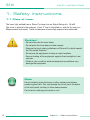
R310
Laser Receiver
Instruction Manual
Another fine solution by
R310
Instruction Manual – English
Laser Receiver R310 II
(BG 830140/1)
Software Version V 6.00
We would like to congratulate you on the purchase of your Status Pro R310 Laser receiver.
Before initial usage you should carefully read the safety instructions as well as the user
guidelines contained in this manual. We wish you every success when using this
Measurement Instrument.
Please note: User Manuals can be amended when improvements or changes to the product range have been carried out. Use the link below to make sure you have the most up to
date version of your User Manual: www.statuspro.com/machine_geometry/documents/.
2
Status Pro – R310 Instruction Manual
CONTENT
Content
1. SAFETY INSTRUCTIONS . . . . . . . . . . . . . . . . . . . . . . . . . . . . . . . . . . . . . . . . . . . . . . . . . . . . . . . . 4
1.1 Class of Laser . . . . . . . . . . . . . . . . . . . . . . . . . . . . . . . . . . . . . . . . . . . . . . . . . . . . . . . . . . . . 4
1.2 Standards . . . . . . . . . . . . . . . . . . . . . . . . . . . . . . . . . . . . . . . . . . . . . . . . . . . . . . . . . . . . . . . . 5
1.3 Advice on batteries / rechargeable cells . . . . . . . . . . . . . . . . . . . . . . . . . . . . . . . . . . . . . 5
1.4 Instrument care . . . . . . . . . . . . . . . . . . . . . . . . . . . . . . . . . . . . . . . . . . . . . . . . . . . . . . . . . . .6
1.5 Maintenance . . . . . . . . . . . . . . . . . . . . . . . . . . . . . . . . . . . . . . . . . . . . . . . . . . . . . . . . . . . . . 6
1.6 Calibration and repair . . . . . . . . . . . . . . . . . . . . . . . . . . . . . . . . . . . . . . . . . . . . . . . . . . . . . 7
1.7 Liability Exclusion . . . . . . . . . . . . . . . . . . . . . . . . . . . . . . . . . . . . . . . . . . . . . . . . . . . . . . . . . 7
2. GETTING STARTED . . . . . . . . . . . . . . . . . . . . . . . . . . . . . . . . . . . . . . . . . . . . . . . . . . . . . . . . . . . . . 8
2.1 Power supply . . . . . . . . . . . . . . . . . . . . . . . . . . . . . . . . . . . . . . . . . . . . . . . . . . . . . . . . . . . . . 8
2.2 Assembly . . . . . . . . . . . . . . . . . . . . . . . . . . . . . . . . . . . . . . . . . . . . . . . . . . . . . . . . . . . . . . . . 9
3. OPERATION . . . . . . . . . . . . . . . . . . . . . . . . . . . . . . . . . . . . . . . . . . . . . . . . . . . . . . . . . . . . . . . . . . 10
3.1 Control and information elements of the R310 II . . . . . . . . . . . . . . . . . . . . . . . . . . . . . . 10
3.2 R310 II keypad . . . . . . . . . . . . . . . . . . . . . . . . . . . . . . . . . . . . . . . . . . . . . . . . . . . . . . . . . . . 11
3.3 Setup Menu of the R310 II . . . . . . . . . . . . . . . . . . . . . . . . . . . . . . . . . . . . . . . . . . . . . . . . . 12
3.4 Display features of the R310 II . . . . . . . . . . . . . . . . . . . . . . . . . . . . . . . . . . . . . . . . . . . . . 13
4. MEASUREMENT . . . . . . . . . . . . . . . . . . . . . . . . . . . . . . . . . . . . . . . . . . . . . . . . . . . . . . . . . . . . . . 14
4.1 Signalling . . . . . . . . . . . . . . . . . . . . . . . . . . . . . . . . . . . . . . . . . . . . . . . . . . . . . . . . . . . . . . . 14
4.2 Distance and Averaging . . . . . . . . . . . . . . . . . . . . . . . . . . . . . . . . . . . . . . . . . . . . . . . . . . 14
4.3 Remotely controlling the Laser using Infra-red . . . . . . . . . . . . . . . . . . . . . . . . . . . . . . 15
4.4 Achieving a level plane using Infra-red . . . . . . . . . . . . . . . . . . . . . . . . . . . . . . . . . . . . . 15
4.5 Measuring objects of different height . . . . . . . . . . . . . . . . . . . . . . . . . . . . . . . . . . . . . . 16
4.6 Checking and calibrating the self-levelling feature of the T330 Laser . . . . . . . . . . . 17
5. TECHNICAL DETAILS . . . . . . . . . . . . . . . . . . . . . . . . . . . . . . . . . . . . . . . . . . . . . . . . . . . . . . . . . . 18
6. ACCESORIES . . . . . . . . . . . . . . . . . . . . . . . . . . . . . . . . . . . . . . . . . . . . . . . . . . . . . . . . . . . . . . . . . 19
7. PRODUCTS AND SERVICE . . . . . . . . . . . . . . . . . . . . . . . . . . . . . . . . . . . . . . . . . . . . . . . . . . . . . 22
6. MEMO . . . . . . . . . . . . . . . . . . . . . . . . . . . . . . . . . . . . . . . . . . . . . . . . . . . . . . . . . . . . . . . . . . . . . . . 23
Status Pro – R310 Instruction Manual
3
R310
SAFETY INSTRUCTIONS
1. Safety instructions
1.1 Class of Laser
The laser light emitted from a Status Pro Laser has an Output Rating of < 1,0 mW.
The Laser is placed in the category „Class 2“ and is classified as safe for the use as a
Measurement instrument. There are however a few safety aspects to be observed:
Caution!
• Do not stare into the laser beam.
• Do not point the laser beam at other people.
• Observe the local safety guidelines on Site and if in doubt consult
the Site safety Engineer.
• Do not use the equipment in damp or moist locations.
• Ensure shading of the equipment against direct sunlight or heat
sources.
• Fluids or rain as well as extreme temperature conditions may
damage the equipment.
Note
Do not violently shake the Laser or other sensors and always
protect against falls. This can damage the structure or the optics
of the instrument resulting in false measurements.
Do not touch rotating parts when in use!
4
Status Pro – R310 Instruction Manual
SAFETY INSTRUCTIONS
1.2 Standards
All Status Pro Laser and Receiver Instruments are developed and manufactured
according to the following CE Standards:
•
•
•
•
•
EN 55 011
EN 55 022
EN 61 000-4-2
EN 61 000-4-3
EN 60 335
1.3 Advice on batteries / rechargeable cells
If the equipment is being stored for a longer period of time or being powered using Mains,
then the batteries should be removed to prevent damage of the instrument through leakage.
When using rechargeable cells always observe the specific charging procedures for the
cells.
Rechargeable cells can be recharged around 1000times when treated correctly, but there
is no guarantee!
Caution!
Do not try to recharge normal batteries. Do not expose batteries
or rechargeable cells to fire or excess heat (Danger of explosion).
Do not mix batteries and rechargeable cells.
Always use batteries and cells of the same kind.
Do not mix old and new batteries or cells.
Status Pro – R310 Instruction Manual
5
R310
SAFETY INSTRUCTIONS
Note
Help to protect the environment! Empty batteries do not belong in
the household waste disposal system. Only deposit empty or
damaged cells at a collection point specially designed for this
purpose.
1.4 Instrument care
Your measurement instrument is designed for use in an industrial environment and can
withstand water splashes or light spray as well as dust. Clean the equipment using a soft
cotton cloth and a mild soap solution. Laser apertures as well as well as sensor areas
should only be cleaned using a soft, dry and dust-free cloth. Do not use paper towels to
clean glass surfaces as they could scratch. Avoid contact with grease, oil or oil-based
solutions when handling the equipment.
1.5 Maintenance
The mechanical components of your equipment are prone to natural wear and tear! If the
Instrument appears to have a technical defect, contact the Manufacturer. Do not try to
repair or open the sensor casing. Attempted repairs through unauthorised personnel
makes the guarantee null and void! Always store the equipment under dry conditions and
use the case for transportation.
To ensure trouble-free processing, simply fill in the form you will find using the following
link: www.statuspro.com/machine_geometry/service_support/calibration_repair
Advice
To be able to identify the equipment when seeking advice always
quote the serial number of the equipment. The Manufacturer does
not accept any responsibility for damage incurred through incorrect
maintenance carried out by non-authorised personnel.
6
Status Pro – R310 Instruction Manual
SAFETY INSTRUCTIONS
1.5 Calibration and repair
To guarantee measurement accuracy, and reliable operation of your
Status Pro Measurement System, it is of utmost importance that the recommended Service Intervals be adhered to. The System should be
checked for serviceability, and re-calibrated by the Status Pro workshops every 12 months.
Within the scope of the service checks, the complete system will also be
examined for possible wear or damage, as well as receiving any software updates. The date of the next service check for your equipment is stamped on the
Status Pro calibration sticker.
To ensure trouble-free processing of the service and calibration checks, simply fill in the
form you will find using the following link
www.statuspro.com/machine_geometry/service_support/calibration_repair.
1.6 Liability Exclusion
The Status Pro GmbH does not accept responsibility for damage incurred through incorrect use or handling of the equipment. To ensure correct usage, a founded knowledge of
the equipment is essential. It is of the utmost importance that you read and understand
the Handbook!
No responsibility will be accepted for damage incurred through ignorance or disregarding
of the operating instructions.
Status Pro – R310 Instruction Manual
7
R310
GETTING STARTED
2. Getting started
The R310 is made up of two „housings“: the Instrument part (I) which contains the electronics and the sensor itself, and the Battery pack (II) which contains the power supply.
I: Instrument part R310
II: Battery pack R310
2.1 Power supply
Battery-powered operation
If, when turning on the Sensor (see Chapter 2), nothing is visible in the Display or if this
symbol is visible:
then new or fresh batteries should be inserted.
To replace the batteries, simply loosen the fixing screw (III) then separate the two
housings.
Observe the following carefully:
• Ensure correct polarity when inserting the batteries
• Only use Alkaline batteries (AA) or NiMh. rechargeable cells, (AA) or Mignon
• When storing the Sensor for longer periods, remove the batteries to prevent
leakage and/or corrosion
Set values and preferences remain stored during battery changes.
8
Status Pro – R310 Instruction Manual
GETTING STARTED
Ensure correct alignment of the guide pins (IV) and holes when remounting the battery
pack, as this ensures correct polarity.
Mains operation
Alternatively, the R310 can be powered using a suitable mains supply and the cable group
BT800066 (optional extra). The cable uses a threaded connector for the sensor side;
ensure correct mounting of the connector with the sensor.
Usage of a mains power supply makes sense when carrying out long-term measurements
or when being used as a permanent monitoring sensor. Furthermore, when the R310 sensor is being powered using Mains, the battery housing can be dismantled which is useful
in tight situations.
2.2 Assembly
The R310 Laser Receiver has a hole on the underside allowing sensor mounting using the
BT 948336 M8 Adapter.
When the sensor has been mounted onto the adapter, the knurled screw (V) can be tightened ensuring exact and reproduceable positioning of the sensor.
To enable othogonal positioning of the R310 sensor to the laser, simply loosen the knurled
VI
VII
V
Adapter M8
Status Pro – R310 Instruction Manual
9
R310
OPERATION
screw (V), turn the sensor as required and tighten the knurled screw again. Tightening the
knurled screw ensures the correct height positioning!. The measurement Adapter also
has an M8 thread which facilitates the mounting of the sensor using a block magnet (BT
943092) or on any other suitable attachment with an M8 thread. The measurement
adapters are often used as a permanently fixed attachment on for example buildings or
large machines enabling the measurement and documentation of any changes in the
structure over a long period of time.
Furthermore, the R310 has four M4 threaded holes, two on the front face of the sensor(VI)
and two on the back of the battery housing (VII) . The sensor can be mounted directly on
the measurement object using the threaded holes or using a suitable adapter.
3. Operation
3.1 Control and information elements of the R310 II:
A) Display
B) Laser aperture
C) Laser position and “set” LEDs
D) Fixing screw
E) Spirit level
F) Set-up keypad
G) Infra-red apertures
H) Power and data socket
The rotating laser beam travels through the
Aperture (B) and strikes the detector.
A value is produced which is displayed over
the Display (A).
The Laser position LEDs (C) show if the Laser
beam is above or below the Zero line.
Using the spirit level (E), the R310 can be vertically adjusted to ensure an orthogonal
alignment of the sensor to the Laser.
All the necessary settings and parameters can be set up using the keypad (F).
10
Status Pro – R310 Instruction Manual
OPERATION
3.2 R310 II keypad:
1) ON/OFF, Escape from the Menu
Use the Power button (1) to turn the
sensor on and off.
Furthermore, this button is used to
exit the Menu.
1
2
2) Display ON / OFF
The Display Button (2) is used to turn
off the display when measuring over long
periods of time to save battery power.
To turn back on simply press again.
3
4
5
6
3) Infra-red control ON / OFF
The IR Button (3) activates the Infra-red
mode. The mode of control has to be
chosen from the Menu. IR Control deactivation through repeated pressing.
4) Menu / Toolbox
Press the Menu button(4) repeatedly to toggle through the Set-up Menu
(see Chapter 3.3).
5) Halving
Pressing the Halving button(5) divides the displayed value by two. Pressing again for
longer than 1 second returns the full value.
6) Zeroing / Set
To „zero“ the displayed value, simply press the Zero/Set button(6). This is useful when
aligning the Laser to a reference object (see Chapter 4 – Measurement).
The “native Zero” of the sensor is returned when the Zero button(6) is pressed for
longer than 1 second.
The Zero/Set button (6) is also used to set a chosen parameter within the Menu.
Status Pro – R310 Instruction Manual
11
R310
OPERATION
3.3 Setup Menu of the R310 II:
Repeated pressing of the Menu button(4) enables scrolling through the points of the Set-up
Menü. The Set LEDs (C) signify whether or not a parameter or position has been activated.
With some of the Menu parameters it is only possible to choose one or the other position.
These Menu positions are marked in green in the following table:
Display
12
Indication Description
POS X
Laser X -axis will be remotely controlled
POS Y
Laser Y- axis will be remotely controlled
POS Z
Laser Z- axis will be remotely controlled
RC 310
IR signal solely for the R310 remote control
AG Lo
Averaging Low: low rate of averaging, quick reacting display
AG Hi
Averaging High: high rate of averaging, slower reacting display
Near
Distance between Laser and Sensor < 25m
Far
Distance between Laser and Sensor > 25m
CAL X
Calibrate X: Calibration of the T330 X-Axis at the present value
CAL Y
Calibrate Y: Calibration of the T330 Y-Axis at the present value
CAL Z
Calibrate Z: Calibration of the T330 Z-Axis at the present value
V XX.X
Volt: Display of the remaining battery power
C XX.X
Celsius: Internal Temperature of the R310
EU
European or Metric System (Display in Millimeter)
US
Imperial System (Display in Inch)
IR 310
Communication with T330 Laser over Infra-red
Cb 310
Communication with T330 Laser using a cable
XX8.88
Software version
Status Pro – R310 Instruction Manual
OPERATION
To set a desired point in the menu, press the Set button (6) , the symbol “set” appears in
the display signifying confirmation.
To leave or exit the menu, press the ON / OFF button (1).
3.4 Display features of the R310 II:
Anzeige
Beschreibung
After turning on the R310 II sensor, the present remaing battery power is
automatically displayed.
This symbol means that the sensor is turned on and ready, but no Laser
beam is reaching the sensor. The decimal point displays which measuring
Unit has been chosen: Second from left= Inch. Third from left = Metric.
If the display was turned off using the Display button (2) and then turned
back on again, all the segments in the display will be visible during the
short display self-test.
This symbol is visible when a parameter or point within the menu has been
set or activated (Set button (6).
After pressing the ON/OFF button during operation the word „sleep“ will be
shortly displayed before the sensor switches off.
When the remaining battery power falls below a preset threshhold, the
word bAtt will be visible. Around 30 minutes time will remain to change
batteries.
If the ambient temperature is too high or too low this symbol will appear.
(Measurement Range: -10°C bis +50°C)
When „Error“ is visible, the sensor will turn itself off and then back on
again. If the sensor is no longer serviceable please contact the customer
services at Status Pro Systems.
Status Pro – R310 Instruction Manual
13
R310
MEASUREMENT
4. Measurement
4.1 Signalling
Positions
of LEDs
All Information concerning the measurement and statusof the
R310 II is shown in the display. When no laser is being detected, the „------„ symbol will be displayed.
If a laser beam is being detected, the actual measurement
value will be displayed. The value depicts where the rotating
laser beam is in relation to the „Zero“ of the sensor. If the sensor is higher than Zero, a positive value will be shown, if the
sensor is lower than Zero, a negative value will be shown.
Additionally, the Position LEDs(C) show if the laser beam is above or below Zero.
If the laser beam is within +/- 0.1mm of the Zero, both LEDs will blink. This feature is useful
when aligning the laser to a reference line over greater distances where the actual measurement value is not visible.
4.2 Distance and Averaging
The R310 II has been designed to be able to operate under different conditions. For different operating ranges between Laser and sensor, choose one of the following parameters
in the Menu:
(Near) or
(Far). To change the rate or Averaging, choose
one of the following from the Menu:
(Low Averaging) , or
(High
Averaging).
Example I: Distance between Laser and Sensor less than 25m. Average ambient
temperature and no air turbulence. In this case activate the following
Parameters:
and
.
Example II: Distance between Laser and Sensor less than 25m, high air turbulence
and/or fluctuating temperature conditions. In this case activate the following
Parameters:
and
.
Example III: Distance between Laser and Sensor greater than 25m, average ambient
temperatures and no air turbulence. In this case activate the following
Parameters:
and
.
Example IV: Distance between Laser and Sensor greater than 25m, high air turbulence
and/or fluctuating temperature conditions. In this case activate the following
Parameters:
und
.
14
Status Pro – R310 Instruction Manual
MEASUREMENT
If the following Mode
has been selected from the Menu, the display will react
quite slowly due to the high rate of averaging. If, on the other hand,
has been
activated, the display will react almost immediately when the sensor is moved, due to the
low rate of averaging; which is useful when adjusting machines.
4.3 Remotely controlling the Laser using Infra-red
The R310 II can transmit signals using Infra-red (IR) when needed, allowing remote controlling of the T330 Rotational Laser and/ or the sending of information to the RC310
Remote Control.
To initiate the remote movement of the T330 Laser, press the Infra-red IR button
(3) on
the keypad of the R310 Sensor, and the Laser will automatically move towards the Zero
position on the R310 sensor in either the X-Axis or the Y-Axis depending upon which axis
has been chosen from the Menu; either
or
. When the Zero position
has been reached, the Laser will be held in this position as long as the Infra-red button is
activated. To “release” the Laser, press the Infra-red button again.
If the
command has been activated in the Menu, the R310 will send an Infra-red
signal containing the present sensor measurement value to the RC310 Remote Control .
This signal is invisible to the T330 Laser.
4.4 Achieving a level plane using Infra-red
1) Place the R330 on the object to be measured, ensuring sight at all four sensor positions.
2) Turn on the T330, activate the rotation and the self-levelling functions.
Status Pro – R310 Instruction Manual
15
R310
MEASUREMENT
3) Place the R310 sensor with magnet mounting directly in front of the T330 Laser (1) and
press “Zero” on the sensor.
4) Move the R310 sensor to the distant end of the plane (2). Ensure the R310 sensor is
adjusted to control the “Y” axis as follows: Using the Menu button, scroll through the
Menu until you reach Pos Y. Set this Axis by pressing the 0 button on the sensor. Exit
the Menu by presssing the Power On/Off button on the sensor, then finally, press the
Infra-red button on the sensor. The laser plane will be automatically „pulled down“ to
Zero (0) in this plane. When the value has reached zero(0) disable the Infra-Red function by pressing the IR button on the sensor.
5) Move the R310 sensor close to the T330 Laser in the plane at 90 Degrees from the Y
Axis(3) and press the Zero button on the sensor. Align the IR mirror on the T330
towards the R310 sensor. Set the IR controlling of the X-Axis as follows: Using the
Menu button, scroll through the Menu until you reach Pos X. Set this Axis by pressing
the 0 button on the sensor. Exit the Menu by presssing the Power On/Off button on the
sensor. Place the sensor at the distant end of the X-Axis (4) and finally, press the IR
button on the sensor. The laser beam will be automatically „pulled down“ to Zero (0)
in this plane. When the value has reached zero(0), disable the Infra-Red function by
pressing the IR button on the sensor.
4.5 Measuring objects of different height
Sometimes when levelling, objects of differing height have to be measured in relation to
each other. To enable this, use spacers (FIX 1-0658) placed between the magnet and the
M8 Adapter. Typically, you would manufacture the spacers to the exact height difference
between the objects, enabling a “Zero” reading when the goal is reached.
16
Status Pro – R310 Instruction Manual
MEASUREMENT
4.6 Checking and calibrating the self-levelling
feature of the T330 Laser
After being transported it makes sense to check, and if necessary, re-calibrate the levelling exactness of the T330 Laser before attempting an exact measurement.
Checking the calibration of the T330 Laser
1. Mount theT330 und R310 at a distance ideally between 5 & 10m, then switch both on.
2. Press the Self Levelling button on the T330.
3. ”Zero” the value on the R310 using the
keypad button.
4. Turn the T330 through 180°. If necessary reactivate the Self Levelling on the T330.
5. The value now shown on the R310 is the doubled Levelling error.
6. Halve the value shown on the R310 by pressing
button on the R310
keypad to receive the Level error to be corrected.
The value now shown on the R310 can be divided by the distance in metres betwen Laser
and sensor to obtain the levelling exactness in mm/metre (should be better than 0,025mm /
1000mm) You can now assess if your Laser is up to the task at hand.
If the Laser needs to be calibrated, continue as follows:
Calibrating the T330 Rotating laser
7. Activate
in the R310 Menü (Y-Axis).
8. Press the Infra-red button
(3) to establish communication between Laser and
Sensor and to initiate remote movement of the Laser towards “Zero”.
Status Pro – R310 Instruction Manual
17
R310
TECHNICAL DETAILS
9. When the T330 has reached Zero (0) enter the R310 Menu and search for the
Feature.
10. To complete the calibration process for this particular Axis, press the 0-Button
(6).
The T330 confirms the calibration by a beep signal and stopping the rotation of the
laser beam.
11. Repeat the test procedure for the other Axis, (X or Y) and calibrate if necessary.
Note
This test solely for checking the self-Levelling of the T330 Laser.
All other tests and checks are carried out before delivery and within the
designated service intervals by Status Pro personnel ( R&K ).
5. Technical Details
Display:
7 Segment LED
Sensor:
80 mm Diode array
Resolution:
0.01 mm
Accuracy:
± 0.02 mm+ 1% non-linearity
Temperature resolution: 0,1°C
Voltage resolution:
0,1 V
Range:
typical: 50 m
Protection class:
IP 54
Housing:
Aluminium
Weight:
680 g (425 g without battery compartment)
Dimensions (wxhxd):
65x150x48 mm (65x150x24 mm without battery compartment)
65
2 x M4 thread holes for fixing
14
140
150
40
88
18
10mm hole for fixing the M8
measuring adapter
4.5
2 x M6
thread holes
for fixing
Status Pro – R310 Instruction Manual
ACCESORIES
6. Accesories
Power Supply Cable (BT 800066)
Mains cable for use with the T310/T330 und R310.
The cable assembly is supplied with a wide range of
adapters for use worldwide and is CE Certified.
R310 Bluetooth Kit (BG 830550)
Bluetooth unit for use as an interface between R310
Sensor and the DU310 Display unit.
The Unit is mounted on the Battery Pack of the R310
Sensor using an adapter plate. The Battery Pack has
to be modified to provide the power supply for the
Bluetooth Unit.
RC 310 (BG 830930)
The RC 310 Unit facilitates remote controlling of the
T310 Laser as well as enabling viewing of measurement values when the R310 is at a distance.
Floor and Wall Mouting Console (BG 830119)
Using the floor mounting console, the R310 Sensor
can be aligned exactly over a Centre Line using the
centreing spike. Levelling of the Sensor is possible
using the mounted spirit level.
Alternatively, the console can be used as a wall
mounting. There are several drillings as well as
threaded holes enabling easy fixing. A 5/8 inch
thread enables mounting using a tripod.
Status Pro – R310 Instruction Manual
19
R310
ACCESORIES
Tape Measure Incremental (BT 989045)
The Tape Measure has been modified specially for
use with the Floor and Wall mounting console. The
tape has a punched hole every 100mm enabling the
attachment of the measure to the console.
This features simplifies the moving or offsetting of a
centreline.
Prism magnet base, switchable (BT 943092)
The magnet has an M8 Thread on the top side for
the Measuring adapter thus providing a solid mounting or the R310 Sensor on any magnetic surface. The
base is finely ground giving high reproducibility
when measuring.
Measuring Adapter M8 (BT 948336)
The Mesuring adapter provides the mounting for the
R310 Sensor. The M8 thread enables fixing of the
Sensor on machine parts to be measured or using
the magnet base as a mobile Mounting.
Extensions for Adapter M8
80 mm (FIX 1-0658-080)
300 mm (FIX 1-0658-300)
600 mm (FIX 1-0658-600)
20
Status Pro – R310 Instruction Manual
ACCESORIES
Battery compartment (BG 830111)
Battery compartment for the R310 Sensor.
For 6 Mignon (AA) Batteries or Rechargeable
cells.
Block magnet with probe tip (BG 830175)
The probe tip acts as an extension of the R310
Sensor enabling exact measurements of points within a measurement grid. The magnet ensures a vertikal and therefore reproducible mounting on the
measurement object.
Block magnet with spring-loaded probe tip
(BG 830195)
The probe tip acts as an extension of the R310
Sensor enabling exact measurements of points within a measurement grid. The magnet ensures a vertical and therefore reproducible mounting on the
measurement object. The spring facilitates a permanent contact of the probe tip with the measurement
surface even when working upside down.
Display unit DU 320 (IT 200410)
Display unit / ultramobile – PC based. For industrial
use; with protectors, internal and external battery
and bluetooth.
Status Pro – R310 Instruction Manual
21
R310
PRODUKTE UND SERVICE
7. Products and Service
Geometrical measurement techniques and alignment have been an issue since the
pyramids.
Today the measurement and alignment of machinery components is an integral part of the
assembly and quality control process. Be it linear guides, presses, flange connections,
drive shafts or cylinder rolls, the precision of the alignment has a significant effect on the
func-tionality of the component. The alignment of these machinery components will often
affect the quality of the manufactured product and also the life-time of the machine components themselves. The use of a laser beam reference together with tradition industrial
measurement techniques has made it possible to build tools which
simplify these alignment procedures.
Status Pro develops and manufactures laser alignment equipment
and we are committed to this process.
Most of our customers are machine
builders, assembly and quality control people. Typically our customers
require a complete solution package
including on-site training and support. When a customised solution is
required, modifications are often necessary,
be it in software, mechanical adaptations or the
sensor housing itself in order to meet customer
requirements.
We and our partner companies all over the world also
provide alignment and industrial surveying
services.
We invite you to visit our web site www.statuspro.com
For more information or just call us at + 49 (0) 2327 - 9881 - 0
22
Status Pro – R310 Instruction Manual
MEMO
8. Memo
Status Pro – R310 Instruction Manual
23
Status Pro Maschinenmesstechnik GmbH
Mausegatt 19
D-44866 Bochum
Phone: + 49 (0) 2327 - 9881 - 0
Fax: + 49 (0) 2327 - 9881 - 81
www.statuspro.com
[email protected]
Distributor
BA 1029E 03/12 · Design / DTP: Seichter & Steffens Grafikdesign, D-44229 Dortmund
Copyright 2012 Status Pro Maschinenmesstechnik GmbH. This brochure or parts thereof may not be copied or reproduced in
any other way without prior approval by Status Pro GmbH. Technical correctness and completeness remain reserved and
may be subject to changes without prior information. Information about mistakes this brochure may contain will be welcome
at any time.