1
34
FIBER-BASED OFDM TRANSMISSION SYSTEMS
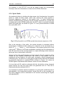
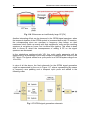
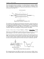
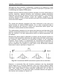
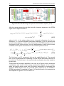
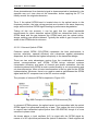
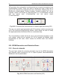
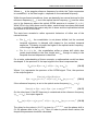
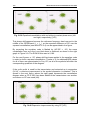
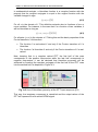
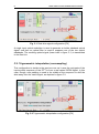
Fig. II.15 RF upconversion based on Intensity Modulation schematic [P4]
II.5.1.2. Optical IQ modulation
If an IQ MZM is used for the optical modulation of the electrical OFDM signal,
only one complex optical OFDM band is obtained, so no optical filter is required
at the transmitter end.
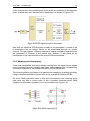
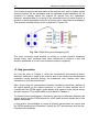
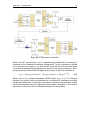
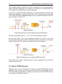
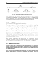
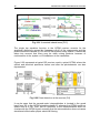
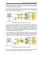
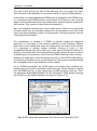
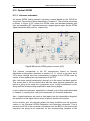
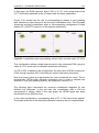
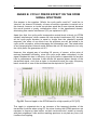
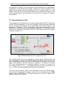
The resulting schematic for this technique is depicted in Figure II.16, where the
real and imaginary components of the OFDM signal are directly fed to the IQ
MZM. For simplicity, oversampling is neglected.
Fig. II.16 Optical IQ modulation schematic [P4]
This scheme provides the possibility of a full-data IFFT input sequence and the
complete DAC bandwidths usage (when no oversampling is applied). Moreover,
few electronic devices are needed for the implementation of this scheme,
though two DACs are required and three bias voltages have to be adjusted for
the IQ MZM.