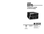
1
USER
MANUAL
MT910A
T1/Fractional T1 CSU/DSU
with Ethernet Bridging
TABLE OF CONTENTS
Section
Page
1.0
............................................2
1.1
1.2
1.3
1.4
1.5
Radio and TV Interference
Equipment Attachment Limitations
FCC Compliance
Service Information
2.0 General Information...............................................................4
2.1 Features
2.2 General Product Description
3.0 Configuration .........................................................................5
3.1 DIP Switch Configuration
3.2 Software Configuration
4.0 Installation ..........................................................................32
4.1 The Model 1001R14 Rack Chassis
4.2 Installing the Interface Driver Board
4.3 Installing the 2720 Into the Rack Chassis
4.4 Connecting to a DTE Device
4.5 Connecting to a DCE Device
4.6 Connecting the T1 Interface
5.0 Operation .............................................................................36
5.1 LED Descriptions
5.2 Loop (V.54 & Telco) Diagnostics
5.3 Bit Error Rate (V.52) Diagnostics
Appendix
Appendix
Appendix
Appendix
Appendix
WARNING!
This device is not intended to be connected to the public telephone network in Europe.
A - Specifications ........................................................41
B - Cable Recommendations......................................42
C - Factory Replacement Parts and Accessories ......43
D - T1 Interface Pin Assignments ..............................44
E - DTE Interface Pin Assignments............................45
1
2
1.3 INDUSTRY CANADA NOTICE
The Canadian Department of Communications label identifies certified equipment. This certification means that the equipment meets
certain telecommunications network protective, operational and safety
requirements. The Department does not guarantee the equipment will
operate to the user's satisfaction. Before installing this equipment,
users should ensure that it is permissible to be connected to the facilities of the local telecommunications company. The equipment must
also be installed using an acceptable method of connection. In some
cases, the company’s inside wiring associated with a single line individual service may be extended by means of a certified connector assembly (telephone extension cord). The customer should be aware that
compliance with the above condition may not prevent degradation of
service in some situations. Repairs to some certified equipment should
be made by an authorized maintenance facility designated by the supplier. Any repairs or alterations made by the user to this equipment, or
equipment malfunctions, may give the telecommunications company
cause to request the user to disconnect the equipment. Users should
ensure for their own protection that the ground connections of the
power utility, telephone lines and internal metallic water pipe system,
are connected together. This protection may be particularly important
in rural areas.
CAUTION: Users should not attempt to make such connections
themselves, but should contact the appropriate electric inspection
authority, or electrician, as appropriate.
1.4 FCC INFORMATION
leased line facilities. The Universal Service Order Code (USOC) is
RJ48. The Facility Interface Codes (FIC) are 04DU9-BN, 04DU9-DN,
04DU9-1KN, and 04DU9-1SN. The Service Order Code (SOC) is 6.0N.
Service
1.544 Mbps
1.544 Mbps
1.544 Mbps
1.544 Mbps
SF format without line power
SF and B8ZS without line power
ANSI ESF without line power
ANSI ESF and B8ZS w/o line power
Service
Code
6.0N
6.0N
6.0N
6.0N
Network
Connection
RJ48C
RJ48C
RJ48C
RJ48C
1.5 FCC PART 68 COMPLIANCE STATEMENT
This equipment complies with Part 68 of FCC Rules. Please note the
following:
1. You are required to request serivce from the telephone company
before you connnect the CSU to a network. When you request serivce,
you must provide the telephone company with the following data. When
you request T1 Service, you must provide the telephone company with
the Facility Interface Code. Provide the telephone company with both of
the following codes: 04DU9-B (1.544 MB D4 framing format) and
04DU9-C (1.544 MB ESF format). The telephone company will select
the code it has available. The Service Order Code(s) (SOC): 6.0N. The
required Universal Service Order Code (USOC) jack: RJ 48C. The
make, model number, and FCC Registration number of the CSU.
2. Your telephone company may make changes to its facilities, equipment, operations, or procedures that could affect the proper functioning
of your equipment. The telephone company will notify you in advance
of such changes to give you and opportunity to maintain uninterrupted
telephone service.
The MT910A has been tested and registered in compliance with the specifications in Part 68 of the FCC rules. A label on the
equipment bears the FCC registration number. You may be requested
to provide this information to your telephone company. Your telephone
company may make changes in its facilities, equipment, operations or
procedures that could affect the proper operation of the MT910A
Series. If this happens, the telephone company should give you
advance notice to prevent the interruption of your service. The telephone company may decide to temporarily discontinue your service if
they believe your MT910A may cause harm to the telephone
network. Whenever possible, they will contact you in advance. If you
elect to do so, you have the right to file a complaint with the FCC. If
you have any trouble operating the MT910A, please contact
Black Box Technical Support 724-746-5500. The telephone
company may ask you to disconnect the equipment from the telephone
network until the problem has been corrected or until you are certain
that the MT910A is not malfunctioning. In accordance with
FCC rules and regulation CFR 47 68.218(b)(6), you must notify the
telephone company prior to disconnection. The following information
may be required when applying to your local telephone company for
3
Facility
Interface
Code
04DU9-BN
04DU9-DN
04DU9-1KN
04DU9-1SN
4
3. If your CSU causes harm to the telephone network, the telephone
company may temporarily discontinue your service. If possible, they will
notify you in advance, but if advance notice is not practical, you will be notified as soon as possible and will be informed of your right to file a complaint
with the FCC.
4. If you experience trouble with the CSU, please contact Black Box
for service or repairs. Repairs should be performed only by
Black Box
5. You are required to notify the telephone company when you disconnect
the CSU from the network.
1.6 SERVICE INFORMATION
All warranty and non-warranty repairs must be returned freight prepaid
and insured to Black Box. All returns must have a Return Materials
Authorization number on the outside of the shipping container. This number
may be obtained from Black Box Customer Sales dept. at: tel: (724)
746-5500 www: http://www.blackbox.com.
NOTE: Packages received without an RMA number will not be accepted.
Black Box technical staff is also available to answer any questions
that might arise concerning the installation or use of your Black Box
MT910A.
2.0 GENERAL INFORMATION
Thank you for your purchase of this Black Box product.
This product has been thoroughly inspected and tested.
If any questions arise during installation or use of the unit, contact Black Box Technical Support at
(724)746-5500.
2.1 FEATURES
• Terminates T1/FT1 Circuits over a 4-Wire RJ-48C interface
• 10Base-T Ethernet bridge
• PPP (Point to Point Protocol, RFC 1661) with Bridge Control
Protocol (RFC 1638)
• Unstructured Rates at 1.544 Mbps
• D4 or ESF Framing Modes
• Supports AMI or B8ZS/B7ZS Line Coding
• Configuration via Software Control Port or Internal DIP Switches
• Six Easy-to-Read LED Indicators Monitor Data & Diagnostics
• Internal or Receive Recover Clocking
• Also Operates as a High-Speed Point-to-Point Modem
• Made in USA
2.2 GENERAL PRODUCT DESCRIPTION
1.7 CE NOTICE
The CE symbol on your Black Box equipment indicates that it
is in compliance with the Electromagnetic Compatibility (EMC) directive and
the Low Voltage Directive (LVD) of the European Union (EU). A Certificate
of Compliance is available by contacting Technical Support.
The NetLink-T1™ MT910A is a single port T1/FT1 CSU/DSU
with Ethernet Bridging that provides high-speed LAN-to-WAN connectivity. Plugging directly into the 10Base-T port of a hub or LAN switch,
the NetLink-T1™ provides T1 or FT1 access at connection data rates
of 1.544 Mbps, nx64, and nx56 (n=1 to 24 channels). The NetlinkT1™ is an excellent choice for internet access as well as LAN-to-LAN
services.
The Netlink-T1™ provides digital access to a local WAN service
provider or directly between two facilities over a dedicated 4-Wire circuit. WAN bandwidth, framing and coding options are programmed via
externally accessible DIP switches or via a VT-100 type terminal using
the rear-mounted EIA-232 Control Port. Netlink-T1™ supports D4/ESF
framing options and AMI/B8ZS/B7ZS line coding. Netlink-T1™ also
supports a full range of system and diagnostic features that make system setup easy. The Ethernet Bridge in this unit requires no configuration at all.
The NetLink-T1™ provides T1 terminations over a modular RJ-48C
jack and comply with jitter tolerance capabilities as specified in ANSI
T1.403 and AT&T TR62411. External power options include 120VAC
and universal interface 100-240VAC. 48VDC and rack card versions
are also available.
5
6
3.0 PPP Operational Background
PPP is a protocol used for multi-plexed transport over a pointto-point link. PPP operates on all full duplex media, and is a symmetric peer-to-peer protocol, which can be broken into three main
components: 1. A standard method to encapsulate datagrams
over serial links; 2. A Link Control Protocol (LCP) to establish, configure, and test the data-link connection; 3. A family of Network
Control Protocols (NCPs) to establish and configure different network layer protocols.
In order to establish communications over a point-to-point link,
each end of the PPP link must first announce its capabilities and
agree on the parameters of the link’s operation. This exchange is
facilitated through LCP Configure-Request packets.
Once the link has been established and optional facilities have
been negotiated, PPP will attempt to establish a network protocol.
PPP will use Network Control Protocol (NCP) to choose and configure one or more network layer protocols. Once each of the network layer protocols have been configured, datagrams from the
established network layer protocol can be sent over the link. The
link will remain configured for these communications until explicit
LCP or NCP packets close the link down, or until some external
event occurs.
The PPP Bridging Control Protocol (BCP), defined in RFC
1638, configures and enables/disables the bridge protocol on
both ends of the point-to-point link. BCP uses the same
packet exchange mechanism as the Link Control Protocol
(LCP). BCP is a Network Control Protocol of PPP, bridge
packets may not be exchanged until PPP has reached the
network layer protocol phase.
3.1 APPLICATIONS
Router
MT910A
Bridge
Ethernet LAN
PEC Device w/ Serial I/F
Figure 1. Cisco router with serial interface, configured as PPP Half Bridge.
For example, the customer site is assigned the addresses
192.168.1.0/24 through 192.168.1.1/24. The address
192.168.1.1/24 is also the default gateway for the remote network. The above settings remove any routing/forwarding intelligence from the CPE. The associated Cisco configuration will
set serial interface (s0) to accommodate half bridging for the
above example.
Authentication is optional under PPP. In a point-to-point
leased-line link, incoming customer facilities are usually fixed
in nature, therefore authentication is generally not required. If
the foreign device requires authentication via PAP or CHAP,
the PPP software will respond with default Peer-ID consisting
of the units Ethernet MAC address and a password which
consists of the unit’s Ethernet MAC address.
Some networking systems do not define network numbers
in packets sent out over a network. If a packet does not have
a specific destination network number, a router will assume
that the packet is set up for the local segment and will not forward it to any other sub-network. However, in cases where
two devices need to communicate over the wide-area, bridging can be used to transport non-routable protocols.
Figure 2 illustrates transparent bridging between two
routers over a serial interface (s0). Bridging will occur
between the two Ethernet Interfaces on Router A (e0 and e1)
and the two Ethernet Interfaces on Router B (e0 and e1).
MT910A
In situations where a routed network requires connectivity
to a remote Ethernet network, the interface on a router can
be configured as a PPP IP Half Bridge. The serial line to the
remote bridge functions as a Virtual Ethernet interface, effectively extending the routers serial port connection to the
remote network. The bridge device sends bridge packets
(BPDU's) to the router's serial interface. The router will
receive the layer three address information and will forward
these packets based on its IP address.
Figure 1 shows a typical Cisco router with a serial interface
configured as a PPP Half Bridge. The router serial interface uses
a remote device that supports PPP bridging to function as a node
on the remote Ethernet network. The serial interface on the
Cisco will have an IP address on the same Ethernet subnet as
the bridge.
7
!
no ip routing
!
interface Ethernet0
ip address 1.1.1.1 255.255.255.0
bridge-group 1
!
interface Serial0
ip address 1.1.1.1 255.255.255.0
encapsulation PPP
bridge-group 1
!
interface Serial1
ip address 2.2.2.2 255.255.255.0
bridge-group 1
!
bridge 1 protocol ieee
!
Serial Interface
T1/FT1 Link
Router A
S0
S1
Router B
e0
Using Bridge-Groups, multiple remote LANs can be
bridged over the wide-area.
LAN
LAN
S1
S0
e0
LAN
LAN
e1
LAN
MT910A
Serial Interface
T1/FT1 Link
Figure 2. Transparent bridging between two routers over a serial interface.
8
3.1.1 Switch S2
Line Framing Options:
The table below shows the default configurations for Switch S2. A
description of all S2 options follows this table.
S2 SUMMARY TABLE
Position
Function
Factory Default
S2-1
Data Rate
On
S2-2
Data Rate
On
S2-3
Data Rate
On
S2-4
Framing & Coding
Off
Selected Option
1.536 Mbps
(DTE Rate)
ESF/B8ZS
S2-5
DS0 Rate
On
64 kbps
S2-6
Clock Mode
Off
Network
S2-7
Clock Mode
Off
Network
S2-8
Reserved
Off
Reserved
Switches S2-1, S2-2, and S2-3
Use Switches S2-1, S2-2 and S2-3 to set the DTE data rate.
Each setting represents an nx56/nx64 setting. Individual channel settings can be configured through the software control port.
S2-1
Off
On
Off
On
Off
On
Off
On
S2-2
Off
Off
On
On
Off
Off
On
On
S2-3
Off
Off
Off
Off
On
On
On
On
Speed
Clear Channel (Unframed)
112kbps/128kbps
224kbps/256kbps
336kbps/384kbps
448kbps/512kbps
672kbps/768kbps
896kbps/1024kbps
1344kbps/1536kbps
D4/Superframe: The D4 framing format, as specified in AT&T
TR62411 is the standard in which twelve frames make up a
superframe. All signaling and synchronization are done inband.
Extended Superframe (ESF): Extended Superframe, as specified in AT&T TR 54016, consists of twenty-four (24) T1
frames. The framing bits are now used for framing, CRC and
the Facility Data Link (FDL). The FDL allows maintenance
messages and information to be passed between the MT910A
and the Central Office.
Line Coding Options:
Alternate Mark Inversion (AMI): This mode does not inherently
account for ones density. To meet this requirement, each time
slot can be reduced to 56 kbps and the Least Significant Bit
(LSB) of each time slot set to one.
Bipolar 8 Zero Substitution (B8ZS): This mode assures proper
bit density in the data stream. In this mode any data pattern
can be transmitted without causing ones density errors. This
mode allows for 64 kbps clear channel timeslots.
Switch S2-5: DS0 Channel Rate
Use Switch S2-5 to set the DS0 rate.
SW2-5
Off
On
Setting
56 kbps
64 kbps
Switch S2-4: Line Framing and Coding
Use Switch S2-4 to control the Network Line Framing and Coding
Options. Set these options to be the same as the Line Framing and
Coding Options given to you by your Service Provider. If you are using
two MT910As together as short range modems, set both units identically.
S2-4
Off
On
Line Framing & Coding
ESF/B8ZS
D4/AMI
9
10
Switch S2-6 and S2-7: Clock Mode
Set Switch S2-6 and S2-7 to determine the MT910As transmitter timing.
S2-6
Off
On
S2-7
Off
Off
Clock Mode
Network Clock. Transmitter timing is
derived from the received line signal.
Internal Clock. Transmitter clock is
derived from an internal oscillator.
NOTE 1: When using the Model MT910A as a high-speed short
range modem, one unit of the link must be configured in Internal
Clock mode, and the opposite end unit must be configured for
Network Clock mode.
If the ERR LED on the front of the unit is flashing (or on) it could
be an indication of a clocking problem. Double check your clock
mode settings and Tx Clock Invert S1-3 settings.
3.1.2 Switch S1
The chart below shows the default configurations for Switch S1. A
description of all S1 options follows this table.
S1 SUMMARY TABE
Position
Function
Factory Default
S1-1
RDL Type
On
S1-2
Reserved
On
S1-3
Tx Clock Invert
Off
S1-4
Line Build Out
Off
S1-5
Selected Option
V.54 RDL
Normal
0dB
Off
S1-6
Reserved
Off
S1-7
S1-8
Reserved
Reserved
Off
Off
Switch S1-1: RDL Type
Switch S2-8 Reserved
Switch S1-1 selects the type of Remote Digital Loopback that the
MT910A will initiate when the RDL is initiated from this unit. The MT910A
will respond to both the V54 and the CSU loopback regardless of the
setting of S1-1
S1-1
On
Off
RDL Type
Initiate a V.54 RDL loop when selected
Initiate a CSU loopback when selected
Switch S1-2: Reserved
11
12
Switch S1-3: Tx Clock Invert
3.2 SOFTWARE CONFIGURATION
Switch S1-3 allows the user to invert the transmit clock originating
in the MT910A. When S1-2 is set for transmit clock, it may be necessary to
invert the transmit clock to allow for delays due to long cables.
The MT910A features a menu-driven command system that
allows you to monitor/configure its operating parameters. Follow the
instructions below to configure the MT910A using the software
selections:
S1-3
On
Off
Tx Clock Invert
Transmit clock is inverted
Transmit clock is normal
1)
Switches S1-4 and S1-5: Line Build Out
Use Switches S1-4 and S1-5 to set the Line Build Out (LBO). The
Line Build Out varies the pulse shape and attenuation of the signal
sent to the network. The amount of Line Build Out depends on
NetLink™ T1’s distance to the last repeater. The telephone company
providing the service will advise on the amount of LBO necessary. In
most cases the default setting will suffice.
SW1-4
Off
On
Off
On
SW1-5
Off
Off
On
On
Function
(0dB)
-7.5dB
-15.0dB
-22.5dB
Switch S1-6 Through S1-8: Reserved
Plug the 9-pin male end of the cable to your terminal or computer’s DB-9 serial port and start up the terminal emulator
software if necessary. Plug the miniature stereo plug into the
rear of the unit. The small recessed jack on the left side of
the unit is the control port jack.
NOTE: If your terminal uses a DB-25 connector, please use a
DB-9 to DB-25 Adapter to connect to the cable.
2)
Power up the terminal and set its RS-232 port as follows:
9600 Baud
8 data bits, 1 stop bit, no parity
Local echo off
ANSI or VT-100 emulation
3)
Here is an example of a terminal emulator setup session. In
normal font are the various parameter types. In bold type are
the values that should be used for best results. Your terminal
program’s setup screen may differ from this one:
Baud rate: 9600
Parity: None
Data Length: 8
Default terminal type:
Local Echo:
Add Line Feeds after CRs:
Received Backspace Destructive:
Backspace key sends:
XON/XOFF software flow control:
CTS/RTS hardware flow control:
DSR/DTR hardware flow control:
13
VT100
Off
Off
On
BS
On
Off
Off
14
Stop Bits: 1
4)
When the unit is first turned on, the terminal screen may
appear blank. Press the [Enter] key. If your serial connection is
good, the unit will immediately display a password prompt.
The following message will appear in the middle of the
screen:
3.2.1 Introduction to Main Menu
After entering the password, you may access all of the system’s
functions and parameters. The Main Menu looks like this:
Black Box
Menu Management
Enter Password: _
5)
Type in the password and press [Enter]. The factory default
password for the unit is (password is case sensitive):
blackbox
HELPFUL HINTS
NOTE: If the entry is incorrect, the password screen will clear
and prompt you again for the correct password. The password
you enter will not be shown. For security, asterisks will be displayed for each letter you type. The maximum length of the
password, which can include any character the terminal can
generate, is 16 characters.
6)
1.
To make a selection, key the highlighted letter that corresponds to a menu selection.
2.
To execute the selection, type [Enter/CR]
3.
To toggle between options on a highlighted selection, Press
[space].
4.
Select d Save Changes from Main Menu after making modifications to any MT910A parameter. Otherwise, changes
will be lost when the MT910A is turned off.
The MT910A will then display the Main Menu screen.
15
16
The Main Menu options are briefly described below.
a
System Configuration options allow you to change various
aspects of the MT910A’s operation, e.g., framing, line coding, and aggregate bandwidth.
b
System Diagnostics/Statistics options allow you to monitor
the network performance, initiate V.54 loops, local loops, and
send test patterns. Network performance parameters are
updated once a second, giving you the ability to quickly determine if there is a problem.
c
Unit Options allow you to customize the MT910A for your
location. You can change the default header names to give
each unit a unique name and password. Also, you can reset
the unit to its default settings without the manual. It also has a
Service Information screen in case you need technical assistance from Black Box.
d
Save Changes. Once you have configured the unit to your
satisfaction, you can save the changes permanently by executing the Save Changes command. This will update the unit’s
configuration and save all the parameters to permanent memory.
e
Logoff. For security, log off the control menu by executing
the Logoff command. This will blank the screen until an
[Enter] key is pressed.
3.2.2 System Configuration
The default System Configuration menu looks like this:
The System Configuration options are described below:
a Line Format: ESF (default)
Options: ESF, D4, UNFRAMED
D4: This is an older, but widely used, line format that does not
provide FDL, so network interface performance cannot be
monitored so easily. AT&T TR 62411 contains the specifications for this format and the ESF. D4 is also known as
Superframe format. According to TR 62411, “The Superframe
format…consists of 12 frames of 193 bits each for a total of
2316 bits. Each 193 bit frame consists of 192 bits preceded by
one framing bit….the framing bit is time shared to both synchronize the terminal equipment and to identify the signaling
frames.” (Sec. 4.1.1)
17
18
ESF: This stands for Extended Superframe Format, a line format
developed by AT&T. AT&T Technical Reference 54016 (TR
54016) defines the ESF, a format which is commonly used to
allow monitoring of the network interface performance over
the Facility Data Link (FDL). AT&T TR 62411 says, “the
Extended Superframe Format “extends” the DS1 superframe
structure from 12 to 24 frames…for a total of 4632 bits. It
redefines the 8 kb/s channel previously used exclusively for
terminal and robbed bit signaling synchronization.” The ESF
provides a 4 kb/s data link, called the FDL, which allows for
in-service monitoring and fast troubleshooting. Certain network services require the ESF.
UNFRAMED:This is a special mode that allows you to achieve the
maximum possible data rate of 1.544 Mb/s (million bits per
second) by using the framing bits for data transmission. There
is no signaling or FDL. This is commonly used for campus
connections, and by the Federal government and the military.
This format is not to be used when connecting to a public carrier’s network without its permission. This provides one channel at a rate of 1.544 Mb/s. In addition, this format can be
used with external clocking.
B8ZS: Bipolar violations occur when consecutive pulses are of
the same polarity. In B8ZS, or Bipolar Eight Zero Substitution,
bipolar violations are introduced deliberately to indicate that
eight zeros have been transmitted. This special encoding is
recognized by the receiver and decoded correctly. See AT&T
TR62411 Section 4.2.2 for a detailed description of B8ZS.
This enables information to be sent over a T1 connection without any constraints on the data’s pulse density. This is the
most acceptable way to accomplish 64 kb/s on each DS0
channel.
B7ZS: This stands for Bipolar Seven Zero Substitution. Instead of
introducing bipolar violations, this method substitutes a one
for a zero in bit 7 (out of 8) of a DS0 channel when the data in
that channel are all zeros. This is a special form of AMI and is
compatible only with special equipment. For most applications,
AMI or B8ZS will suffice.
c
DS0 Line Rate: 64kbps (default)
Options: 64kbps, 56kbps
b Line Coding: B8ZS (default)
Options: AMI, B8ZS, B7ZS.
AMI: Alternate Mark Inversion defines a pulse as a “mark”, a
binary one, as opposed to a zero. In a T1 (DS1) network connection, signals are transmitted as a sequence of ones and
zeros. Ones are sent as pulses, and zeros are sent as
spaces, i.e., no pulse. Every other pulse is inverted from the
previous pulse in polarity, so that the signal can be effectively
transmitted. This means, however, that a long sequence of
zeros in the data stream will cause problems, since the
CSU/DSU receiving the signal relies on the signal to recover
the 1.544 Mb/s clock. To get around this problem, one method
is to limit the data rate per channel (known as a DS0,
because it is a 64 kb/s portion of the DS1 frame or superframe) to 56 kb/s and forcing a pulse in the last data bit to
ensure a minimum pulse density in the signal. If you must use
AMI with a DS0 data rate of 64 kb/s, you should ensure that
the data terminal equipment connected to the unit provides a
minimally acceptable pulse density. For this reason, there are
advantages to using B8ZS instead.
19
64kbps: Also known as Clear Channel, this takes full advantage
of the available bandwidth in a DS0 channel. Implementing it
usually requires B8ZS line coding. In certain cases, special
equipment may implement Clear Channel using AMI or B7ZS.
Consult the equipment manual for compatibility. Your carrier
will advise you on whether to use 64 or 56 kb/s. Campus
applications may not have such restrictions, enabling you to
use 64kbps. In Unframed format, the 24 DS0s and the framing
bits are combined to provide 1.544Mb/s for your use.
56kbps: This uses only the first seven bits of the DS0, limiting the
data rate per DS0 channel to 56 kb/s. Your carrier will advise
you on whether to use 64 or 56 kb/s. This is not available
when using the Unframed format.
20
d Clocking: Network (default)
Options:
Network, Internal, External
Network: This is the most commonly used setting when connect
ing to a carrier’s network. In this mode, the unit recovers the
clock from the received signal and uses it to transmit data. In
this way the unit remains synchronized to a master clock.
Incampus applications, one of the units must be set to Internal
clock, and the other end is set to Network clock. At all times,
there must be only one clock source. Otherwise, clock slips
and framing errors and bit errors may occur.
Internal: This is commonly used in campus applications, where
the unit is not connected to the public telephone network
directly. In this mode, the unit uses the on-board oscillator as
the transmit clock source.
e
Line Build Out (dB): 0 – 133 feet, 0 dB (default)
Options:
-7.5 dB
-15.0 dB
-22.5 dB
This controls the transmitter signal strength and pulse shape. For
most applications, the default setting will suffice. When connecting to a
carrier connection, the carrier will determine what LBO is necessary.
0dB provides the highest signal strength and therefore the longest distance, while –15.0 dB provides the lowest usable signal strength. The
last setting, –22.5 dB, is usually only used to test the line and should
not be used in normal applications.
f
ESF Data Link: ANSI T1.403 (default)
Options: ANSI T1.403, AT&T TR54016
ANSI T1.403: This ANSI developed standard (see ANSI T1.4031995: Network-to-Customer Installation—DS1 Metallic
Interface) uses the FDL to send and receive one second
Performance Report Messages (PRMs). The messages contain the NI performance over the last four seconds. Thus, up
to three consecutive messages may be lost without loss of
information. It is available only with ESF. When ANSI T1.403 is
selected, requests to send AT&T performance reports (ref.
AT&T TR 54016) are ignored.
AT&T TR54016: Developed by AT&T, this FDL method differs
principally from the ANSI method in two ways: First, the ANSI
method transmits messages continuously, whereas the AT&T
method transmits a performance report only upon a request
from the remote end for a report. Second, the AT&T method
provides a historical summary, up to the last 24 hours, of NI
performance. Only the service provider or special test equipment can send these requests. When AT&T TR54016 is
selected, ANSI PRMs are still transmitted by the unit, but only
PRMs sent by the carrier will be recognized. To receive PRMs
from another customer unit (i.e., in a campus application),
select ANSI T1.403. When the frame is not ESF, the FDL is
disabled.
g ESF Carrier Loops: Enabled (default)
Options: Enabled, Disabled
The ESF format provides the CO the ability to put the customer
installation’s MT910A into loopback mode. The MT910A recognizes these special messages that are sent over the FDL. When
enabled, the unit will respond to these loopback commands and go into
or out of loopback mode. When disabled, the unit will not respond,
although it still recognizes the loopback commands. When in loopback,
the unit will remain in loopback until a loopback exit command is
received or when the loopback timer times out. See Unit Options
(Section 3.2.4) to make Loop Timeout choices. This feature allows the
remote user to regain control should one be locked out after a loopback is initiated.
21
22
h
Remote In-band Loops: Enabled (default)
Options: Enabled, Disabled
In ESF, D4 and Unframed formats, the unit can respond to special
repeating codes in the data stream that represent loopback commands. The command to loop up (go into loopback) is a repeating pattern of 00001s. This pattern overwrites the normal data. When this
code is detected for 5 seconds, the unit will go into loopback if the
Remote In-band Loopback is Enabled. When a repeating code of 001s
is received for 5 seconds, the unit loops down (goes out of loopback).
The delayed recognition guards against false starts, since the code
must be present for a long time continuously. When Disabled, the unit
will recognize the codes but will not respond to them. The loopback
timeout also applies to this feature.
i
unit. This will cause the unit to enter a special mode. Then turn off the
unit and change the switch settings to the desired settings. When you
turn the unit on again, the unit will be set up with the selected switch
settings.
n DS0 Channel Configuration Menu: [ Bandwidth/# Channels =
1,536/24 ] (default)
The DS0 Channel Configuration Menu has a sub-menu that looks
like this:
V.54 Loops (RDL Only): Enabled (default)
Options: Enabled, Disabled
This is a special in-band loopback facility that sends a special
pseudo-random pattern over the data stream. This is the only remote
loopback that the unit can initiate. This is useful for campus applications when you need to put a remote unit in loopback. The remote unit
responds to the V.54 loopback command, and the whole process takes
only a few seconds to complete. This setting will enable/disable RDL
from being initiated from either the control port or the DTE interface. It
will also enable/disable the unit to respond to the V.54 command if
received over the line. The duration of the loopback is limited by the
loopback timeout setting. (See Unit Operations, paragraph 3.2.4, on
pages 32 and 33.)
j
Default Config Source: Switch (default)
You may configure the MT910A to operate with any combination of active and inactive DS0 channels in this screen. When you execute the Save Changes command, the selected settings will be saved
to permanent memory, and the system will be updated to operate with
the new channel settings.
Option: EEPROM, Switch
The MT910A can be initialized via the configuration in the onboard permanent memory (EEPROM) or via the internal DIP switches
(Switch). Once the unit is powered up, you may change the settings
through the control port or the DIP switches.
NOTE: In Unframed format, the Bandwidth Selected will display
“1,544k,” and the Total Channels will display “n/a.” When the DS0
Channel Rate is 56kbps, the Bandwidth Selected will be a multiple
of 56k, not of 64k. When using the DIP switches to set the bandwidth, the starting channel is always channel 1.
If you do not have a terminal, you may force the unit to use the
DIP switches as the default configuration source by turning off the unit,
setting all the DIP switches to the ON position, then powering on the
23
24
3.2.3 System Diagnostics
b
The System Diagnostics/Statistics screen looks like this:
Remote Loop Idle (default)
The Remote Digital Loopback (RDL) test checks the performance
of both the local and remote MT910As, as well as the communication link between them. Data from the local DTE is sent across the
entire communication circuit and looped back to the local DTE.
The MT910A Initiating a RL can be in one of the following
states:
Idle
No user-controlled loopbacks are active.
TxPr
The MT910A is sending the preparatory phase pattern
lasting for approximately 2 -5 seconds.
WtAk
The MT910A is waiting for an acknowledgement from
the remote unit. If the remote unit does not respond, the
WtAk message will remain on the screen.
RxAk
The MT910A has received an acknowledgement from
the remote unit.
NOTE: This screen is updated once per second.
Tout
The MT910A is waiting before entering the Remote
Loopback test mode.
The System Diagnostics/Statistics options and functions are
described below.
TM
The MT910A has successfully negotiated the Remote
Loopback test and is in control of the remote unit. You
may send a test pattern at this point by pressing:
a
Local Loop: Idle (default)
c <spacebar>
The Local Loop is a bi-lateral loopback in which the data from the
local DTE and the data from the remote unit are looped back to their
respective sources (See Section 5.3). Activate this loop to test the
each of the DTE’s connection to the MT910A.
The Local Loop test has four states:
Idle
No user-controlled loopbacks are active.
LL
The MT910A is in local loopback mode.
Off
The MT910A is in remote or CO initiated loopback
mode or sending a pattern. Local loopback is disabled.
LocP
The MT910A is in Local Loopback mode, and is sending a test pattern.
TxTr
The MT910A is sending a Terminate Loopback message to the remote unit. If the remote unit does not
respond, the local unit will return to the Idle state.
Tx1s
If the remote MT910A responds to the local NetLinkT1™’s terminate loopback request, the local unit then
sends an all ones pattern before returning to the Idle
state
TxP
The MT910A is sending a test pattern while in Test
Mode
IdlP
The MT910A is sending a test pattern in place of data.
The MT910A is not in test mode.
The MT910A receiving a RL can be in one of the following states:
25
26
c
RxPr
The MT910A is receiving a preparatory pattern.
NI STATUS
Sack
The MT910A, upon receiving a preparatory pattern,
sends an acknowledgement message.
RL
The MT910A is in remote loopback mode.
RxTr
The MT910A is receiving a terminate loopback message.
Wt1s
The MT910A is waiting for a sequence of all ones and
will time out if it does not receive it.
The Network interface (NI) status is shown
in the middle of the Diagnostics/Statistics
screen. The brackets are empty when the
link is operating normally. In this example,
various two or three-letter messages are
displayed within the brackets, illustrating
what you may see if the MT910A is not
connected at all or is in a loss of signal
condition. Here are the eight status messages.
IdleP
TheMT910A is sending a QRSS, 511 or 2047 pattern.
Off
The MT910A is in local loopback.
Test Pattern Idle (default)
Receiver Carrier Loss [RCL] occurs when 192 consecutive zeros
have been detected at the network interface. RCL clears when a pulse
is detected.
Options: Idle or Sending
To send a pattern, press the ‘c’ key and press <spacebar> to send
the test pattern. The “OK” message indicates the received test pattern
is error-free. The “BE” message indicates errors in the received pattern.
Idle
Error Insertion Off (default)
Options: On, Off
You may inject intentional errors into the test pattern by turning
Error Insertion ON. The Error (ERR) LED will blink once per second.
e
Frame Bit Error [FE] occurs when there is an error in the framing bit
sequence. This may happen due to a disconnected line, mismatched
framing formats or severe errors in the data stream. This error may
indicate a noisy line or cable condition. This error may indicate a noisy
line or cable connection if the frames appear to be set correctly.
Indicates that MT910A is not sending a pattern.
Sending Indicates that MT910A is sending a pattern.
d
Excessive zeros [EXZ], i.e., lack of pulses, detected. This condition
may occur if the unit is not connected to the network, in which case the
EXZ is displayed continuously. If EXZ comes on intermittently, there
may be a frame, line code or data rate mismatch between the near and
far-end units.
Severe Frame Error [SE] occurs when the framing error exceeds a
certain threshold of errors. This may happen due to a disconnected
line, an extremely noisy connection, or mismatched framing.
Loss of Sync [LOS] occurs when the T1 framer in the unit cannot
synchronize itself to the received data stream. This may happen due to
a disconnected line.
Out of Frame [OOF] occurs when no valid frame structure can be
found. This may happen due to a disconnected line or mismatched
framing or mismatched framing.
Selected Pattern
Options: QRSS, 511, or 2047
Use this option to select the test pattern used to test the link.
27
Alarm Indication Signal [AIS] indicates that the remote unit or the
central office is sending a Blue Alarm, because it is not receiving a signal; the alarm is an unframed all-ones signal, mainly used to keep the
line alive and to indicate that it is not receiving any signal. This may
indicate that the local unit is receiving a good signal, but that the transmit link may be broken.
28
Receive Alarm Indication [RAI] indicates that the local unit is receiving a Yellow Alarm. This alarm is sent by the remote unit or the central
office when it loses the received signal. This indicates the local unit’s
transmitted signal is not reaching the remote unit.
Rx Level The MT910A displays the current received signal
strength in dB. There are four level ranges detected:
+2 to –7.5
-7.5 to –15
-15 to –22.5
< -22.5
Rx PRM
The NetLink-T1™ transmits ANSI performance report messages
once a second when the framing mode is ESF. When the ESF Data
Link is set to ANSI T1.403, the unit recognizes PRMs with addresses
of 38h or 3Ah. The address 3Ah indicates the PRM is coming from a
Carrier, whereas the address 38h indicates the PRM is coming from a
Customer. When the ESF Data Link is set to AT&T TR54016, the unit
recognizes Carrier-originated PRMs, which have an address of 3Ah.
Rx PRM: 00010000000300023289
Valid Interval Count & Current Interval Time
Current DIP Switch Settings
The Valid Interval Count and Current Interval Time display the
number of valid 15 minute intervals in the last 24 hours and the number of seconds which have elapsed in the current interval, respectively.
The Valid Interval Count saturates at the count of 96 (96 * 15min = 24
hours), while the Current Interval Time rolls over after 900 counts.
When the counter rolls over, it is reset to zero, and the Interval Counter
is incremented by one if the count is less than 96.
The Switch settings are displayed here to
facilitate troubleshooting your unit without
opening up the unit first.
Valid Interval Count: [96]
Current Interval Time: [899]
Error Counters
These error counters give a second-by-second snapshot of the
link performance. To clear all counters, press the [Backspace] key. If
your keyboard does not have this key, you can press a two-key combination to affect the same result: Hold down the [Ctrl] key and then
press the [H] key. This will send to the unit the Ctrl-H character, which
is the same as pressing the [Backspace] key.
ERR SEC:
UAS SEC:
SE SEC:
BE SEC:
LOF SEC:
0
557
0
0
0
0
209
0
0
0
Errored Seconds in Current Interval....
Unavailable Seconds
Severely Errored Seconds
Bursty Errored Seconds
Loss of Frame Error Seconds
29
30
3.3.6 Unit Information
Loop Timeout
The Unit Options screen looks like this (factory default):
The Loop Timeout setting can be set to one of the following:
00:05 =
00:10 =
00:15 =
00:30 =
00:45 =
01:00 =
01:30 =
02:00 =
03:00 =
NEVER =
five minutes
ten minutes
fifteen minutes
thirty minutes (default setting)
forty-five minutes
one hour
90 minutes
two hours
three hours
forever—the unit will remain in loopback without user
intervention.
MT910A
Tx Data Clock
Header Line 1 & Header Line 2
Headers 1 and 2 are provided for easy identification of your unit
after installation. You may want to give each unit a unique name via
the header lines to help distinguish one unit from another. You can
enter a header up to 40 letters long. Two lines provide 80 letters for
your use. That’s a lot of flexibility!
This option selects the clock that is used to accept the Transmit
Data from the DTE interface. Standard DTE interfaces will transmit
data with respect to the External Clock. In some cases a DTE interface
will transmit with respect to the Transmit clock sent out from the MT910A.
Please review the information provided with your DTE equipment for
more information on its' operation. In most cases when there are errors
on the line only in the direction of the transmit data either Tx Data
Clock or Tx Clock Invert can be changed to solve the problem.
Password
Tx Clock Invert
The Password facility provides security by allowing only those who
know the correct password to configure the unit via the control port.
You can still configure the unit via the DIP switches. The password can
be up to 16 characters long, with no restriction on the combination of
characters you can use, so be sure to remember the password. If you
lose your password, you will lose the ability to access the unit via the
control port.
This option allows the user to invert the transmit clock originating
in the MT910A. When Tx Data Clock is set for transmit clock, it may be
necessary to invert the transmit clock to allow for cable delays.
Set to Default Configuration
You may set the NetLink-T1™ to its factory default configuration,
except for the header lines and the password, by executing the Set to
Default Configuration command.
31
32
4.0 INSTALLATION
4.2 Connecting the 10Base-T Ethernet Port to a Hub
The 10Base-T interface is configured as DTE (Data Terminal
Equipment), just like a 10Base-T network interface card in a PC.
Therefore, it “expects” to connect to a 10Base-T Hub using a straightthrough RJ-45 cable. Use the diagram below (Figure 9) to construct a
cable to connect the 10 BaseT interface to a 10Base-T Hub.
The MT910A is equipped with DTE, network, and power interfaces. This section briefly describes connection to each.
4.1 Connecting the 10Base-T Ethernet Port to a PC (DTE)
Control
Port
10BaseT Interface
T1 Interface
10BaseT Port
RJ-45 Pin No.
1 (TD+)
2 (TD-)
10Base-T Hub
RJ-45 Pin No.
1 (RD+)
2 (RD-)
3 (RD+)
6 (RD-)
3 (TD+)
6 (TD-)
Figure 5: Connecting the 10Base-T Ethernet Port to a Hub
1
2
3
4
5
6
7
8
1
2
3
4
5
6
7
8
TD+ (data output from MT910A)
TD- (data output from MT910A)
RD+ (data input to MT910A)
(no connection)
(no connection)
RD- (data input to MT910A)
(no connection)
(no connection)
Figure 3: Connecting the 10Base-T Ethernet Port to a PC
The 10Base-T Interface is configured as DTE (Data Terminal
Equipment). If the MT910A is to to connect to another DTE
device such as a 10Base-T network interface card, construct a
10Base-T crossover cable and connect the wires as shown in the diagram below (Figure 4).
4.3 T1/FT1 INTERFACE CONNECTION
The Network Line Interface Line is an eight position keyed modular jack configured as a RJ-48C. This interface will need to be configured to match the line parameters (i.e. framing, line coding, etc.) supplied by the central office.
1
2
3
4
5
6
7
8
1 RX Data (TIP)
2 RX Data (RING)
3 (no connection)
4 TX Data (TIP)
5 TX Data (RING)
6 (no connection)
7 (no connection)
8 (no connection)
}
}
From Network
To network
Figure 6. MT910A twisted pair line interface.
10BaseT Port
RJ-45 Pin No.
1 (TD+)
2 (TD-)
10Base-T DTE
RJ-45 Pin No.
1 (TD+)
2 (TD-)
3 (RD+)
6 (RD-)
3 (RD+)
6 (RD-)
Figure 4: 10Base-T Cross-over Cable Connection
NOTE:
If the MT910A is being used for private short range
modem applications, the twisted pair cable connected to
its port will need to be a crossover cable. See Appendix
D for Interface pin assignments.
33
34
5.0 OPERATION
Once the NetLink-T1™ is installed and configured properly it is
ready to place into operation. This section describes the function of
the LED indicators, and the use of the loopback and pattern test
modes.
5.1 LED DESCRIPTIONS
The NetLink-T1™ is equipped with six LED indicators that monitor
the status of communication. Figure 12 (below) shows the location of
the LEDs on the NetLink-T1™ Series front panel.
9 pulses = Detected LAN receive frame(s) too
large
10 pulses = Detected LAN receive frame(s) not
octet aligned
11 pulses = Detected LAN receive frame(s) with
bad CRC
ALM
10BaseT T1/FT1 CSU/DSU
The alarm LED indicates the presence of a
Blue or Yellow Alarm, or Out of Frame condition. The ALM LED will blink on every
half-second. Alarms may occur due to:
•
•
•
•
Loss of Synchronization
Loss of Frame
AIS (Blue Alarm)
RAI (Yellow Alarm)
Figure 7: MT910A Front Panel
T1 Link
Solid green indicates that the end to end TI
link is up. Signifying that the link is active.
The TI link LED is off when the link is down
10BT Link
(Active Green) Solid green indicates that
the 10BaseT Ethernet interface has detect
ed a valid SQE heartbeat, signifying a valid
10BaseT connection.
Status
Blinks yellow from one to eleven times to
indicate system status. Each pulse pattern
is separated by a 2 second “off” period.
Greater pulse patterns have
higher
priority (buffer saturation has greater priority
than an empty MAC table). Valid system
statuses are:
1 pulse =
2 pulses =
3 pulses =
4 pulses =
5 pulses =
6 pulses =
system status is okay
no MAC entries in the
MAC Address Table
Clear to Send (CTS) or
Carrier Detect (DCD) from
base unit are not asserted
IM1/I buffer is saturated
WAN receive frame(s) too large
WAN receive frame(s) not octet
aligned
7 pulses = WAN receive frame(s) aborted
8 pulses = Detected WAN receive frame(s) with
CRC
35
ER
The error LED indicates various error conditions, including framing bit errors, excessive
zeros, controlled slips, severe errors, or bit
errors (when sending V.52 test patterns).
When sending a test pattern, the LED will
remain lit if the unit does not receive the
identical pattern. When it receives the correct pattern, the LED will turn off. If error
insertion is on, the LED will blink once a
second if everything is operating properly.
TM
The test indicator LED blinks with a specific
pattern depending on the type of test mode.
When the unit is in local analog loop, the
LED will blink on briefly. When the unit is in
remote loop, the TM LED will blink off
briefly. When the unit is sending a test pattern or is putting the remote unit into
V.54/CSU loopback, the TM LED will stay
on. These are the test modes:
•
•
•
•
V.54/CSU Loopback & V.52 Patterns
D4 Line Loop (CO initiated)
ESF Line Loop (CO Initiated)
ESF Payload Loop (CO Initiated)
36
5.2 LOOP (V.54 & TELCO) DIAGNOSTICS
5.2.2 Operating Remote Digital Loopback (RL)
The NetLink-T1™ offers three V.54 loop diagnostics and is compatible with two Telco loop diagnostics. Use these diagnostics to test
the CSU/DSU and any communication links. These tests can be activated via the software control port (See Section 3.2.3 System
Diagnostics), via signals on the serial port interface or the front panel
switch.
5.2.1 Operating Local Loopback (LL)
The Local Loopback (LL) test checks the operation of the local
NetLink-T1™, and is performed separately on each unit. Any data
sent to the local NetLink-T1™ in this test mode will be echoed
(returned) back to the user device (i.e., characters typed on the keyboard of a terminal will appear on the terminal screen).
T1/FT1 CSU/DSU
Model MT910A
T1/FT1 CSU/DSU
Model MT910A
Receive
Recover
Clocking
Internal
Clocking
Ethernet
Device
Cable Span
Clock/
Data
Data
The Remote Digital Loopback (RL) test checks the performance of
both the local and remote NetLink-T1™, as well as the communication
link between them. Any characters sent to the remote NetLink-T1™ in
this test mode will be returned back to the originating device (i.e, characters typed on the keyboard of the local terminal will appear on the
local terminal screen after having been passed to the remote NetLinkT1™ and looped back).
Receive
Recover
Clocking
Internal
Clocking
Ethernet
Device
Ethernet
Device
Cable Span
Clock/
Data
Ethernet
Device
T1/FT1 CSU/DSU
Model MT910A
T1/FT1 CSU/DSU
Model MT910A
Clock/
Data
Data
x
Clock/
Data
Clock/
Data
Data
Model MT910A
Model MT910A
RL Initiated
Figure 9. Local Loopback
Data
Clock/
Data
Model MT910A
LLB Initiated
Model MT910A
Figure 8. Local Loopback
To perform a LL test, follow these steps:
1.
Activate LL. This may be done in one of two ways:
a.
b.
There are two Remote Loops that can be initiated from the
NetLink-T1 unit: (1) V.54 Loop, and; (2) CSU Loop. The user can
select the type of loop that can be initiated from the System
Diagnostics/Statistics screen or with Switch S1-1. When a loopback
is initiated this is the type of loop that the unit uses to loop up the
remote unit. NOTE: The NetLink-T1 will respond to both loops regardless of the state of the RDL Type.
Enter a Local Loop from the System
Diagnostics/Statistics menu and toggle the <Spacebar>
until “LL” appears next to the a Local Loop option.
To perform an RDL test, follow these steps:
Toggle the front panel switch to the “Local” position.
1.
2.
Verify that the data terminal equipment is operating properly
and can be used for a test.
3.
Perform a V.52 BER (bit error rate) test as described in
Section 5.3. If the BER test equipment indicates no faults,
but the data terminal indicates a fault, follow the manufacturer’s checkout procedures for the data terminal. Also, check
the interface cable between the terminal and the NetLink-T1.
37
Activate RDL. This may be done in two ways:
a.
Enter b Remote Loop from the System
Diagnostics/Statistics menu and toggle the <Spacebar>
until “RL” appears next to the b Remote Loop option.;
b.
Set the front panel switch to ‘Remote’.
38
2.
Perform a bit error rate test (BERT) using the internal V.52
generator (as described in Section 5.3), or using a separate
BER Tester. If the BER test indicates a fault, and the Local
Line Loopback test was successful for both NetLink™s, you
may have a problem with the twisted pair line connection.
To perform a V.52 test, follow these steps:
1.
Activate the local loopback or remote loopback diagnostic.
2.
Activate the test pattern. This may be done in one of two
ways:
5.2.3 CSU Loop
The NetLink-T1™ also responds to central office initiated loop commands. The NetLink-T1™ will implement the “loop up” command
when it recognizes the pattern “10000” in the data stream for a minimum of 5 seconds. The “loop down” command is implemented by the
pattern “100” in the data stream for a minimum of 5 seconds.
When operating in ESF framing mode, loopback commands are
issued via the Facility Data Link (FDL). The line loop message will
cause a loop back before data enters the framer portion of the CSU.
The payload loop message will cause the NetLink-T1™ to loop data
after the framer portion of the CSU.
The NetLink-T1™ will respond to Universal Loopback De-activate
to clear all central office loops.
a.
Enter e Selected Pattern from the System
Diagnostics/Statistics menu and toggle the <Spacebar>
until the desired test pattern appears.
b.
Enter c Test Pattern and toggle the [Spacebar] to send
the selected pattern.
c.
One of two result codes will appear to the right of the
Test Pattern listing:
OK Indicates that the received test pattern is error-free.
BE Indicates that there are errors in the test pattern (to
deliberately insert errors in the pattern, toggle
Error Insertion to ON).
5.3 BIT ERROR RATE (V.52) DIAGNOSTICS
The NetLink-T1™ offers three V.52 Bit Error Rate (BER) test patterns. These test patterns may be invoked along with the LAL and
RDL tests to evaluate the unit(s) and the communication links.
When a 511, 2047, or QRSS test is invoked, the NetLink-T1™
20
generates a pseudo-random bit pattern of 511 bits, 2047 bits or 2
bits, respectively, using a mathematical polynomial. The receiving
NetLink- T1™ then decodes the received bits using the same polynomial. If the received bits match the agreed upon pseudo-random pattern, then the NetLink-T1™(s) and the communication link(s) are functioning properly.
511
Initiates a built-in 511 bit pseudo-random
pattern generator and detector.
2047
Initiates a built-in 2047 bit pseudo-random
pattern generator and detector.
QRSS
Initiates a built-in 2 bit pseudo-random
pattern generator and detector.
20
39
40
APPENDIX B
ETHERNET 10BASE-T SPECIFICATIONS
APPENDIX A
Black Box NETLINK-T1 MT910A
SPECIFICATIONS
DTE Interface:
10Base-T on RJ-45F
DTE Data Rates:
10Mbps
LAN Connection:
RJ-45, 10Base-T, 802.3 Ethernet
Protocol:
PPP (RFC 1661) with Bridging Control
(RFC 1638)
WAN Speed:
1.544 Mbps
WAN Connection:
RJ-48C
Nominal Impedance:
100 Ohms
MAC Address Table Size:
4096 entries
DTE Interface:
10Base-T Ethernet (802.3)
MAC Address Aging:
MAC addresses deleted after 8 minutes
of inactivity
Line Coding:
AMI/B8ZS
Frame Buffer:
512 Frames
Line Framing
D4/ESF/Unframed
Frame Latency:
1 frame
Receive LBO:
Automatic
Indicators:
Transmit LBO:
Selectable - 0, 7.5,
15, or 22.5 dB, plus DSX-1
T1 Link, 10Base-T Link, Ethernet
Status, Loss of Frame Sync, Error, Test
Mode
Humidity:
Up to 90% non-condensing
Clock Options:
Internal or network clock
Temperature:
0 to 50o C
Diagnostics:
Responds to CO-initiated D4 loopup
and loopdown codes, ESF line loop
and payload loop FDL messages,
Universal Loopback De-activate message,V.54 Remote Loop, Local Loop,
and V.52 BER Patterns:
511,2047,QRSS
Standards:
AT&T TR62411, TR54016, ANSI
T1.403
Power Supply:
120VAC, 60 Hz to 5VDC 300mA wallmount transformer or UI 100-240VAC,
50-60 Hz to 5 VDC, 2A desktop transformer
Dimensions:
3.5”L x 2.1”W x 0.78”H (9.0 x 5.3 x 1.9
cm)
5.0’’ L x 42’’ W x 1.5’’ H
41
42
APPENDIX D
APPENDIX C
Black Box NETLINK-T1™ MT910A
FACTORY REPLACEMENT PARTS
AND ACCESSORIES
Black Box NETLINK-T1™ MT910A
INTERFACE PIN ASSIGNMENT
RJ-48C T1 (DS0) Network Interface
(Female Modular Jack)
Pin #
1
2
4
5
Signal
RX Data (TIP 1)
RX Data (RING1)
TX Data (TIP)
TX Data (RING)
TRS Jack (RS-232 Control Port)
Pin #
Tip
Ring
Sleeve
Signal
Tx Data
Rx Data
Ground
Direction
From MT910A
To MT910A
RS-232 Control Port (Signals at DB-25 Connector)
Pin#
3
2
7
Signal
Receive
Transmit Data
Ground
Signal Direction
From MT910A
To MT910A
RS-232 Control Port (Signals at DB-9 Connecter)
Pin#
2
3
5
43
Signal
Receive
Transmit Data
Ground
Signal Direction
From MT910A
To MT910A
44