1
User Manual
V1.04
Table of Contents
Chapter 1. System Overview ................................................................................................................................................................................................. 1
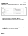
1.1 Introduction of "Air Force One 5" ................................................................................................................................................................................ 1
1.2 System Concept ................................................................................................................................................................................................................... 2
1.3 Product Benefit .................................................................................................................................................................................................................... 3
1.4 Specification.......................................................................................................................................................................................................................... 4
Chapter 2. Base Installation................................................................................................................................................................................................... 8
2.1 Hardware Installation....................................................................................................................................................................................................... 8
2.1.1 Package Contents ............................................................................................................................................................................................................ 8
2.1.2 Panel Function Descriptions ...................................................................................................................................................................................... 8
2.1.3 Hardware Installation Steps ....................................................................................................................................................................................10
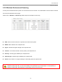
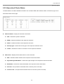
2.2 Web Management Interface Instructions ..............................................................................................................................................................11
2.3 Applications in Wireless Network ............................................................................................................................................................................13
Chapter 3. AP Mode Configuration ...................................................................................................................................................................................17
3.1 External Network Connection ....................................................................................................................................................................................17
3.1.1 Network Requirement ................................................................................................................................................................................................17
3.1.2 Configuration LAN IP ..................................................................................................................................................................................................18
3.2 Wireless LAN Network Creation ................................................................................................................................................................................19
3.2.1 Wireless General Setup ..............................................................................................................................................................................................19
3.2.2 Wireless Advanced Setup ..........................................................................................................................................................................................21
3.2.3 Create Virtual AP ........................................................................................................................................................................................................25
3.2.3.1 Virtual AP Overview ................................................................................................................................................................................................25
3.2.3.2 Virtual AP Setup.........................................................................................................................................................................................................26
3.2.4 Black Wireless Clients.................................................................................................................................................................................................29
3.3 Wireless Network Expansion ......................................................................................................................................................................................30
3.4 System Management .......................................................................................................................................................................................................32
3.4.1 Configuration Management......................................................................................................................................................................................32
3.4.2 Configure System Time ..............................................................................................................................................................................................34
3.4.3 Configure UPnP ..............................................................................................................................................................................................................35
3.4.4 Configure SNMP Setup................................................................................................................................................................................................36
3.4.5 Backup / Restore and Reset to Factory ...............................................................................................................................................................38
3.4.6 Firmware Upgrade .......................................................................................................................................................................................................39
3.4.7 Network Utility ..............................................................................................................................................................................................................40
3.4.8 Reboot ................................................................................................................................................................................................................................41
3.5 Observer Status .................................................................................................................................................................................................................42
3.5.1 System Overview...........................................................................................................................................................................................................42
3.5.2 Associated Clients Status...........................................................................................................................................................................................44
3.5.3 Show WDS Link Status ...............................................................................................................................................................................................45
3.5.4 Extra Information .........................................................................................................................................................................................................46
3.5.5 Event Log ..........................................................................................................................................................................................................................48
Chapter 4. WDS Mode Configuration...............................................................................................................................................................................49
4.1 External Network Connection ....................................................................................................................................................................................49
4.1.1 Network Requirement ................................................................................................................................................................................................49
4.1.2 Configuration LAN IP ..................................................................................................................................................................................................50
4.2 Wireless Network Expansion ......................................................................................................................................................................................51
4.2.1 General Setup .................................................................................................................................................................................................................51
4.2.2 Advanced Setup .............................................................................................................................................................................................................53
4.2.3 WDS Setup .......................................................................................................................................................................................................................57
4.3 System Management .......................................................................................................................................................................................................58
4.3.1 Configuration Management......................................................................................................................................................................................58
4.3.2 Configure System Time ..............................................................................................................................................................................................60
4.3.3 Configure UPnP ..............................................................................................................................................................................................................61
4.3.4 Configure SNMP Setup................................................................................................................................................................................................62
4.3.5 Backup / Restore and Reset to Factory ...............................................................................................................................................................64
4.3.6 Firmware Upgrade .......................................................................................................................................................................................................65
4.3.7 Network Utility ..............................................................................................................................................................................................................66
4.3.8 Reboot ................................................................................................................................................................................................................................67
4.4 Observer Status .................................................................................................................................................................................................................68
4.4.1 System Overview...........................................................................................................................................................................................................68
4.4.2 WDS List............................................................................................................................................................................................................................70
4.4.3 Extra Information .........................................................................................................................................................................................................71
4.4.4 Event Log ..........................................................................................................................................................................................................................73
Chapter 5. CPE Mode Configuration ................................................................................................................................................................................74
5.1 External Network Connection ....................................................................................................................................................................................74
5.1.1 Network Requirement ................................................................................................................................................................................................74
5.1.2 Configure WAN Setup..................................................................................................................................................................................................75
5.1.3 Configure DDNS Setup ................................................................................................................................................................................................78
5.1.4 LAN Setup .........................................................................................................................................................................................................................79
5.2 Access Point Association ...............................................................................................................................................................................................81
5.2.1 Configure Wireless General Setting ......................................................................................................................................................................81
5.2.2 Wireless Environment Scanning ............................................................................................................................................................................83
5.2.3 Create Wireless Profile ...............................................................................................................................................................................................84
5.3 System Management .......................................................................................................................................................................................................86
5.3.1 Configuration Management......................................................................................................................................................................................86
5.3.2 Configure System Time ..............................................................................................................................................................................................88
5.3.3 Configure UPnP ..............................................................................................................................................................................................................89
5.3.4 Configure SNMP Setup................................................................................................................................................................................................90
5.3.5 Backup / Restore and Reset to Factory ...............................................................................................................................................................92
5.3.6 Firmware Upgrade .......................................................................................................................................................................................................93
5.3.7 Network Utility ..............................................................................................................................................................................................................94
5.3.8 Reboot ................................................................................................................................................................................................................................95
5.4 Restrain Users ....................................................................................................................................................................................................................96
5.4.1 IP Filter Setup .................................................................................................................................................................................................................96
5.4.2 MAC Filter Setup ...........................................................................................................................................................................................................98
5.4.3 QoS Setup .........................................................................................................................................................................................................................99
5.5 Internal Service Sharing ............................................................................................................................................................................................. 101
5.5.1 DMZ .................................................................................................................................................................................................................................. 101
5.5.2 Virtual Server (IP/ Port Forwarding) ............................................................................................................................................................... 102
5.6 Observer Status .............................................................................................................................................................................................................. 104
5.6.1 Overview ........................................................................................................................................................................................................................ 104
5.6.2 Station Statistics ......................................................................................................................................................................................................... 106
5.6.3 Extra Info ....................................................................................................................................................................................................................... 108
5.6.4 Event Log ....................................................................................................................................................................................................................... 110
Chapter 6. Universal Repeater Mode Configuration .............................................................................................................................................. 111
6.1 External Network Connection ................................................................................................................................................................................. 111
6.1.1 Network Requirement ............................................................................................................................................................................................. 111
6.1.2 Configuration LAN IP ............................................................................................................................................................................................... 112
6.2 Access Point Association ............................................................................................................................................................................................ 113
6.2.1 Configure Wireless General Setting ................................................................................................................................................................... 113
6.2.2 Wireless Advanced Setup ....................................................................................................................................................................................... 115
6.2.3 Wireless Environment Scanning ......................................................................................................................................................................... 119
6.2.4 Create Wireless Profile ............................................................................................................................................................................................ 120
6.3 Wireless LAN Network Creation ............................................................................................................................................................................. 122
6.3.1 Create Virtual AP ..................................................................................................................................................................................................... 122
6.3.1.1 Virtual AP Overview ............................................................................................................................................................................................. 122
6.3.1.2 Virtual AP Setup...................................................................................................................................................................................................... 124
6.3.2 Black Wireless Clients.............................................................................................................................................................................................. 127
6.4 System Management .................................................................................................................................................................................................... 128
6.4.1 Configuration Management................................................................................................................................................................................... 128
6.4.2 Configure System Time ........................................................................................................................................................................................... 130
6.4.3 Configure UPnP ........................................................................................................................................................................................................... 131
6.4.4 Configure SNMP Setup............................................................................................................................................................................................. 132
6.4.5 Backup / Restore and Reset to Factory ............................................................................................................................................................ 134
6.4.6 Firmware Upgrade .................................................................................................................................................................................................... 135
6.4.7 Network Utility ........................................................................................................................................................................................................... 136
6.4.8 Reboot ............................................................................................................................................................................................................................. 137
6.5 Observer Status .............................................................................................................................................................................................................. 138
6.5.1 System Overview........................................................................................................................................................................................................ 138
6.5.2 Associated Clients Status........................................................................................................................................................................................ 140
6.5.3 Remote AP ..................................................................................................................................................................................................................... 141
6.5.4 Extra Information ...................................................................................................................................................................................................... 142
6.5.5 Event Log ....................................................................................................................................................................................................................... 145
Appendix A.
Windows TCP/IP Settings ............................................................................................................................................................... 146
Appendix B.
Valid Characters when using WMI ............................................................................................................................................... 148
Appendix C.
System Manager Privileges ............................................................................................................................................................. 152
Appendix D.
Enabling UPnP in Windows XP .................................................................................................................................................. 153
User Manual
Air Force One 5
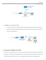
Chapter 1. System Overview
1.1 Introduction
Kozumi outdoor high power Wireless 5.8Ghz CPE is the point of connection to Wireless Outdoor Network for service
provider deploying last mile services to business or residential broadband subscribers. Network administrators can create
multiple subscriber service tier using per-subscriber rate limiting features, and manage centrally. Kozumi outdoor CPE/AP
utilizes a 200mW output Tx Power connect to the WiFi mesh or WDS infrastructure and provides the subscriber with an
Ethernet connection for a local access.
Kozumi outdoor high power Wireless 5.8Ghz CPE supports three operational modes, AP mode, WDS mode, CPE mode
and Universal Repeater mode respectively with built-in remote management features simplify the deployment and reduce
cost for continued maintenance of the outdoor bridge.
1. Access Point : It can be deployed as a traditional fixed wireless Access Point
2. WDS : It can be expanded Wireless Service as WDS Link
3. CPE (Customer Premises Equipment) : It is a wireless gateway with NAT and DHCP Server functions. That
connects to Wireless Internet Service Provider's (WISP)
4. Universal Repeater : It extends the range of your wireless network while simultaneously allowing wired and
wireless clients to access
1
User Manual
Air Force One 5
1.2 System Concept
The "Air Force One 5" is designed with WISP’s deployment needs in mind, especially the management capability and
permission control with respect to management roles. The "Air Force One 5" can be used in many applications as below
scenarios:
Wireless CPE for Multi Dwelling Unit, MDU, /Multi Tenant Unit, MTU complexes, such as apartments, dormitories,
and office complexes.
Outdoor Access Point for school campuses, enterprise campuses, or manufacture plants.
Indoor Access Point for hotels, factories, or warehouses where robust devices are required.
Public hotspot operation for café, parks, convention centers, shopping malls, or airports.
Wireless coverage for both indoor and outdoor premises for private resorts, acreage estate/home yards, or golf
course communities.
2
User Manual
Air Force One 5
1.3 Product Benefit
IEEE 802.11n Draft 2.0 Compliance in 2Tx / 2Rx Design
Support IEEE 802.11n and 802.11a
Operates in the 5GHz ISM Band
Enables Bandwidth of up to 300Mbps(Tx), 300Mbps(Rx) link rate
Topology : Point to Point ; Point to Multi Point
Operation Modes : Access Point(with WDS function), WDS(Pure WDS), CPE (Router Client) and Universal Repeater
Security with 802.1X, WPA, and WPA2
Support QoS & WMM
Integrated Power over Ethernet (PoE)
Multiple Virtual AP & Capability of Client Isolation
Business-class WLAN Security and Client Authentications
Provide Advanced Wireless Setting
Support Web Management and SNMP MIB II
Over Load Current Protection
Wide Range Voltage Support (12-68VDC)
Weather-Proof Housing (IP 68 Approved), M-13 RJ45 and N-Type Connector
Client Isolation Through Layer 2 VLAN Technology
QoS (Quality of Service) for bandwidth management and traffic prioritization
3
User Manual
Air Force One 5
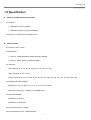
1.4 Specification
Wireless and Wired Interface Standard
Wireless :
1. IEEE 802.11a (Up to 54Mbps)
2. IEEE 802.11n(draft 2.0) (Up to 300Mbps)
Ethernet : 1 x IEEE 802.3 and IEEE 802.3u
Wireless Radio
Frequency band : 5GHz
Modulations :
1. 802.11a : OFDM with BPSK, QPSK, QAM and 64QAM
2. 802.11n : BPSK, QPSK, 16-QAM, 64-QAM
Channels :
USA (Channel 36, 40, 44, 48, 52, 56, 60, 64, 149, 153, 157, 161)
Japan (Channel 34, 38, 42, 46)
Europe (Channel 36, 40, 44, 48, 52, 56, 60, 64, 100, 104, 108, 112, 116, 120, 124, 128, 132, 136, 140)
Data Rate with auto fallback :
IEEE802.11a : 54, 48, 36, 24, 18, 12, 11, 9, 6, 5.5, 2 and 1 Mbps
IEEE802.11n(draft 2.0) : 300Mbps (Tx), 300Mbpx (Rx)
Channel Bandwidth :
IEEE802.11a : 20 MHz
IEEE802.11n : 20/40 MHz
Receiver Sensitivity : -97dBm
RF transmission power : 23dBm /200mW
4
User Manual
Air Force One 5
Antenna: Embedded 14dbi Dual Phase Patch Antenna
General Access Point Features
Number of ESSID : 8
Number of associated clients per AP : 32
Multiple mode : AP Mode, WDS Mode, CPE Mode and Universal Repeater Mode
WDS Mode : to extend wireless coverage by connecting wirelessly to another WDS capable AP. Support up to 4
WDS links
HT Tx/Rx Stream selection : 1 or 2
Channel Bandwidth setting : 20MHz or 20/40MHz
Short Slot support
A-MSDU and A-MPDU support
Maximal MPDU density for TX aggregation
DFS (Dynamic Frequency Select) support
TX burst support
Beacon interval : adjustable to best adapt to the deployment environment
IAPP : to facilitate faster roaming for the stations among different APs nearby
RTS and fragmentation control
Adjustable transmission power : 100 %
Wireless site survey : for scanning the surrounding access points for connection
VLAN tag support
Gateway Features in the CPE Mode
Built-in NAT mode : to support IP sharing on the LAN side for multiple users(subscribers) to get access to the
5
User Manual
Air Force One 5
Internet
Support three reconnect type on PPPoE Mode : Always On, On Demand and Manual
MAC Cloning
Built-in DHCP server for issuing local IP addresses
Built-in DHCP client and PPPoE client on the Wi-Fi WAN side
Built-in DNS proxy
Built-in Dynamic DNS
IP/ Port forwarding and DMZ
IP/ MAC rule filtering
Bandwidth traffic Shaping
Security
Data encryption : WEP (64/128-bits), WPA/WPA2 with TKIP or AES-CCMP
User Authentication : WEP, IEEE 802.1X, WPA-Enterprise, WPA2-Enterprise, MAC ACL
Setting for TKIP/ CCMP/AES key's refreshing period
Hidden ESSID : broadcast SSID option can be turned off to prevent SSID broadcast to the public
Station Isolation setting : when enabled, all stations associated with this AP can not communicate with each other
Support data encryption over WDS link (WEP, AES, TKIP)
Quality of Service (QoS)
Download and Upload traffic control
Packet classifications via DSCP (Differentiated Services Code Point)
Control Policy by IP/ IP Ranges/ MAC/ Service
Layer-7 Protocol Support
6
User Manual
Air Force One 5
Traffic Analysis and Statistics
No. of Max. Policy setting : 10
DiffServ/ TOS
IEEE802.11p/ COS
IEEE802.11Q Tag VLAN priority control
IEEE802.11e WMM
Administration
Web-based management interface
Remote configuration and management
Remote firmware upgradeable
Software one-button-click to reset back to factory defaults
Utilities for system configuration backup and restoration
SNMP MIBII support (v1/ v2c/ v3)
NTP time synchronization
Syslog client
Support Event Log
CLI access via Telnet and SSH
WEB Access via HTTP and HTTPS
Support statistics on total transmission encountered and transmitting error occurred
Support UPnP (Universal Plug and Play)
Hardware Specifications
Plastic case : weather proof
7
User Manual
Air Force One 5
On board over load current protection
LED Indication : Power x 1; Ethernet x 1; Wireless x 1
Physical and Power
PoE : DC 24V/ 0.5 A
Form factor : Pole Mountable
Dimensions (W x D x H) : 6.5” x 3.8” x 1.9” (165 x 96 x 48 mm)
Weight: 0.35kg
Environment
Operation temperature : -30℃ ~ 60℃
Storage temperature : -30℃ ~ 85℃
Operation humidity : 100% maximum (Non-condensing)
Storage humidity : 100% (Non-condensing)
Standard Pack Accessories
Air Force One 5
x1
Quick Installation Guide
x 1 (English/Spanish)
CD-ROM (with User Manual and QIG)
x1
Power Adapter
x1
DC24V 0.5A
POE injector
x1
Mounting Kit
x2
8
User Manual
Air Force One 5
Chapter 2. Base Installation
2.1 Hardware Installation
2.1.1 Package Contents
Air Force One 5
x1
Quick Installation Guide
x1
CD-ROM (with User Manual and QIG)
x1
Power Adapter
x1
POE injector
x1
Mounting Kit
x2
It is highly recommended to use all the supplies in the package instead of substituting any components by other
suppliers to guarantee best performance.
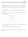
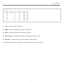
2.1.2 Panel Function Descriptions
Rear Panel
Front Panel
9
User Manual
Air Force One 5
1.
Reboot Button :
Unscrew the screw and click Reset button to restart system or reset to
default configurations.
Press and hold the Reset button for 2 seconds to restart system. The LED except Power indicator will be off
before restarting.
Press and hold the Reset button for more than 10 seconds to reset the system to default configurations.
2.
Power :
Green LED ON indicates power on, and OFF indicates power off.
3.
WLAN :
Green LED FLASH indicates Wireless Transmit.
4.
Ethernet :
Green LED ON indicates connection, OFF indicates no connection
5.
PoE RJ45 port :
For connecting PoE LAN cable
10
User Manual
Air Force One 5
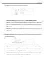
2.1.3 Hardware Installation Steps
Please follow the steps mentioned below to install the hardware of "Air Force One 5" :
11
User Manual
Air Force One 5
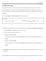
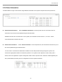
2.2 Web Management Interface Instructions
"Air Force One 5" supports web-based configuration. Upon the completion of hardware installation, "Air Force One 5" can
be configured through a PC/NB by using its web browser such as Internet Explorer version 6.0.
Default IP Address : 192.168.2.254
Default IP Netmask : 255.255.255.0
Default User Name and Password :
The default user name and password for both root manager account and admin manager account are as follows :
Manager Account
Root Account
Admin Account
User name
root
admin
Password
default
admin
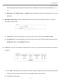
Step
IP Segment Set-up for Administrator's PC/NB
Set the IP segment of the administrator's computer to be in the same range as "Air Force One 5" for accessing the
system. Do not duplicate the IP Address used here with IP Address of "Air Force One 5" or any other device within
the network
Example of Segment :
The value for underlined area can be changed as desired; the valid range is 1 ~ 254. However, 254 shall be avoided
as it is already used by "Air Force One 5"; use 10 as an example here.
IP Address : 192.168.2.10
IP Netmask : 255.255.255.0
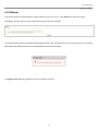
Launch Web Browser
Launch as web browser to access the web management interface of system by entering the default IP Address,
http://192.168.2.254, in the URL field, and then press Enter.
12
User Manual
Air Force One 5
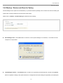
System Login
The system manager Login Page then appears.
Enter “root” as User name and “default” as Password, and then click OK to login to the system; the root manager
account is used as an
example here.
Login Success
System Overview page will appear after successful login.
13
User Manual
Air Force One 5
14
User Manual
Air Force One 5
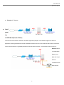
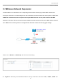
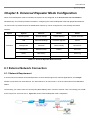
2.3 Applications in Wireless Network
Air Force One 5 is a multiple mode system which can be configured either as a wireless gateway or an access point as
desired. It also can be used as WDS link for network extension This section depicts different applications in AP Mode,
WDS Mode, CPE Mode and Universal Repeater Mode.
Configuration in AP Mode (Access Point + WDS)
An access point can be either a main, relay or remote base station. A main base station is typically connected to the
wired Ethernet. A relay base station relays data between remote base stations, wireless clients or other relay stations
to either a main or another relay base station. A remote base station accepts connections from wireless clients and
passes them on to relay or main stations
Example 1 : Access Point without WDS
It can be deployed as a tradition fixed wireless Access Point
Example 2 : Access Point with WDS
It can be deployed as a tradition fixed wireless Access Point and provides WDS link for network extension
15
User Manual
Air Force One 5
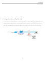
Example 3 : Wireless Repeater Bridge
It may also be refereed to as a wireless repeater mode because it appears to bridge and accept wireless
clients simultaneously (unlike traditional bridging). Please noted, throughput under this setting is halved for
all clients connected wirelessly.
Configuration in WDS Mode (Pure WDS)
An access point can be either a main, relay or remote base station. A main base station is typically connected to the
wired Ethernet. A relay base station relays data between remote base stations or other relay stations to either a main
or another relay base station. In this mode, it can only provide WDS link and wireless clients cannot access
16
User Manual
Air Force One 5
simultaneously.
Example 1 : Point-to-Point
Example 2 : Point-to-Multi-Point
17
User Manual
Air Force One 5
Example 3 : Repeater
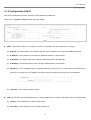
Confi
gurat
ion
in CPE Mode (Router Client)
It can be used as an Outdoor Customer Premises Equipment (CPE) to receive wireless signal over last mile
applications, helping WISPs deliver wireless broadband Internet service to new residential and business customers.
In this mode, the AFO-5 is a gateway with NAT and DHCP Server functions. The wired clients of AFO-5 are in
different subnet
from Main Base
Station and it
does not accept
wireless
connections from
client devices.
18
User Manual
Air Force One 5
Configuration in Universal Repeater Mode
It can be used as an Universal Repeater to receive wireless signal over last mile applications, helping WISPs deliver
wireless broadband Internet service to new residential and business customers. In this mode, the wired clients of
AFO-5 are in the same subnet from Main Base Station and it accepts wireless connections from client devices.
19
User Manual
Air Force One 5
Chapter 3. AP Mode Configuration
When AP mode is activated, the system can be configured as an Access Point. This section provides information for
configuring the AP mode with graphical illustrations. "Air Force One 5" provides functions as stated below where it can be
configured via a user-friendly web based interface.
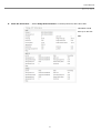
Option
Functions
System
Wireless
Utilities
Status
Operating Mode
General Settings
Profiles Settings
System Overview
LAN
Advanced Settings
Firmware Upgrade
Clients
Management
Virtual AP
Network Utility
WDS Status
Time Server
WDS Setup
Reboot
Extra Info
UPNP
Event Log
SNMP
Table 3-1: AP Mode Functions
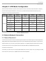
3.1 External Network Connection
3.1.1 Network Requirement
If you want to develop a wireless network to allow wireless clients or Stations (STA) to access wirelessly within the
coverage area, in this mode, the “Air Force One 5” (AFO-5) connected directly to a wired LAN provides a connection point
for wireless clients.
The first step is to get a Default Gateway IP Address from system manager and connect it to the LAN port of “Air Force
One 5”. Figure 3-1 shows Access Point on a Wired LAN Configuration
20
User Manual
Air Force One 5
Figure 3-1 Access Point on a Wired LAN Configuration
21
User Manual
Air Force One 5
3.1.2 Configuration LAN IP
Here are the instructions for how to setup the local IP Address and Netmask.
Please click on System -> LAN and follow the below setting.
Mode : Check either “Static IP” or “Dynamic IP” button as desired to set up the system IP of LAN port .
Static IP : The administrator can manually setup the LAN IP address when static IP is available/ preferred.
IP Address : The IP address of the LAN port; default IP address is 192.168.2.254
IP Netmask : The Subnet mask of the LAN port; default Netmask is 255.255.255.0
IP Gateway : The default gateway of the LAN port; default Gateway is 192.168.2.1
Dynamic IP : This configuration type is applicable when the "Air Force One 5" is connected to a network with the
presence of a DHCP server; all related IP information will be provided by the DHCP server automatically.
Hostname : The Hostname of the LAN port
DNS : Check either “No Default DNS Server” or “Specify DNS Server IP” button as desired to set up the system DNS.
Primary : The IP address of the primary DNS server.
Secondary : The IP address of the secondary DNS server.
22
User Manual
Air Force One 5
802.1d Spanning Tree
The spanning tree network protocol provides a loop free topology for any bridged LAN. The Spanning Tree Protocol,
which is also referred to as STP, is defined in the IEEE Standard 802.1d.
Change these settings as described here and click Save button to save your changes. Click Reboot button to activate
your changes
23
User Manual
Air Force One 5
3.2 Wireless LAN Network Creation
The system manager can configure related wireless settings, General Settings, Advanced Settings, Virtual AP Setting,
Security Settings, and Access Control Settings.
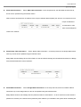
3.2.1 Wireless General Setup
The administrator can change the data transmission, channel and output power settings for the system. Please click on
Wireless -> General Setup and follow the below setting.
MAC address : The MAC address of the Wireless interface is displayed here.
Band Mode : Select an appropriate wireless band; bands available are 801.11a or 802.11a/n mixed mode.
Client Isolation : Select Enable, all clients will be isolated from each other, that means all clients cannot reach to
other clients.
Transmit Rate Control : Select the desired rate from the drop-down list; the options are auto or ranging from 1 to
54Mbps only for 802.11a mode.
Country : Select the desired country code from the drop-down list; the options are US, ETSI, JP and NONE.
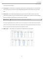
Channel : The channel range will be changed by selecting different country code. Below depicts the channel range
for different Country.
Country
Channel
US
36, 40, 44, 48, 52, 56, 60, 64, 149, 153, 157, 161
ETSI
36, 40, 44, 48, 52, 56, 60, 64, 100, 104, 108, 112, 116, 120, 124, 128, 132, 136, 140
JA
36, 40, 44, 48
NONE
36, 40, 44, 48, 52, 56, 60, 64, 100, 104, 108, 112, 116, 120, 124, 128, 132, 136, 140, 149, 153, 157, 161
24
User Manual
Air Force One 5
Tx Power : You can adjust the output power of the system to get the appropriate coverage for your wireless network.
Specify digit numbers between 1 to 100 (the unit is %) for your environment. If you are not sure which setting to
choose, then keep the default setting, 100%.
When Band Mode select in 802.11a/n mixed mode, the HT(High Throughput) settings should be shown-up
immediately.
HT TxStream/RxStream : Select 1 or 2 from the drop-down list
Operating Mode :
Mixed Mode : In this mode packets are transmitted with a preamble compatible with the legacy 802.11a/g, the
rest of the packet has a new format. In this mode the receiver shall be able to decode both the Mixed Mode
packets and legacy packets.
Green Field : In this mode high throughput packets are transmitted without a legacy compatible part.
25
User Manual
Air Force One 5
Channel Bandwidth : The "20/40” MHz option is usually best. The other option is available for special circumstances.
Guard Interval : Using “Auto” option can increase throughput. However, it can also increase error rate in some
installations, due to increased sensitivity to radio-frequency reflections. Select the option that works best for your
installation.
MCS : This parameter represents transmission rate. By default (Auto) the fastest possible transmission rate will be
selected. You have the option of selecting the speed if necessary.
Reverse Direction Grant(RDG) : Disable or enable reserve direction grant. Default is enabled.
Extension Channel : When “20/40” channel bandwidth has been chosen, you should select extension channel to get
higher throughput.
A-MSDU : Aggregated Mac Service Data Unit. Select Enable to allow aggregation for multiple MSDUs in one MPDU
Default is disabled.
Auto Block ACK : Disable or enable auto block ACK. Default is enabled.
Decline BA Request : Disable or enable decline BA request. Default is disabled.
Change these settings as described here and click Save button to save your changes. Click Reboot button to activate
your changes. The items in this page are for AP's RF general settings and will be applied to all VAPs.
26
User Manual
Air Force One 5
3.2.2 Wireless Advanced Setup
The administrator can change the RTS threshold and fragmentation threshold settings for the system. Please click on
Wireless -> Advanced Setup and follow the below setting.
Beacon Interval : Enter a value between 20 and 1024 msec. The default value is 100 milliseconds. The entered time
means how often the beacon signal transmission between the access point and the wireless network.
DTIM Interval : A DTIM is a countdown informing clients of the next window for listening to broadcast and multicast
messages. When the wireless router has buffered broadcast or multicast messages for associated clients, it sends
the next DTIM with a DTIM Interval value. Wireless clients detect the beacons and awaken to receive the broadcast
and multicast messages. The default value is 1. Valid settings are between 1 and 255.
Fragment Threshold : The value specifies the maximum size of packet allowed before data is fragmented into
multiple packets. Please use this value to tune the wireless connection if lots of retransmission happens. Enter a
value ranging from 256 to 2346.
RTS Threshold : Tuning the Request to Send, RTS threshold will help the system control its access to medium and
alleviate the hidden node problem. Enter a value ranging from 1 to 2347.
Short Preamble : The short preamble provides 56-bit Synchronization field to improve WLAN transmission efficiency.
Check Enable button for using Short Preamble, and Disable for using the Long Preamble, 128-bit Synchronization
field, option.
Short Slot : Enable or disable short slot. Default is enabled.
Tx Burst : Click Enable button to activate Tx Burst, and Disable to deactivate Tx Burst. Enable the Tx Burst can
27
User Manual
Air Force One 5
increase transmission throughput.
Pkt_Aggregate : Increase efficiency by aggregating multiple packets of application data into a single transmission
frame. In this way, 802.11n networks can send multiple data packets with the fixed overhead cost of just a single
frame.
IEEE802.11H : Select Enable to enable DFS(Dynamic Frequency Selection). Default is Enable. When a DFSenabled radio is operating on one of the following channels, the wireless device uses DFS to monitor the operating
frequency and switch to another frequency or reduce power as necessary:
DFS Channels
52, 56, 60, 64, 100, 104, 108, 112, 116, 120, 124, 128, 136, 140
The maximum legal transmit power is greater for some 5 GHz channels than for others. When the wireless device
randomly selects a 5 GHz channel on which power is restricted, the wireless device automatically reduces transmit
power to comply with power limits for that channel in that regulatory domain.
WMM Capable :
Select Enable, the configuration field of WMM parameters should appear.
When you enable WMM Capable, the “Tx Burst” will be Disabled automatically by system.
28
User Manual
Air Force One 5
WMM Parameters of Access Point : This affects traffic flowing from the access point to the client station
Queue
Data Transmitted
AP to Clients
AC_BK
Background.
AC_BE
AC_VI
Best Effort
Video
AC_VO
Voice
Priority
Description
High throughput. Bulk data that requires maximum throughput and is not timesensitive is sent to this queue (FTP data, for example).
Medium Medium throughput and delay. Most traditional IP data is sent to this queue
High
Minimum delay. Time-sensitive video data is automatically sent to this queue
Time-sensitive data like VoIP and streaming media are automatically sent to this
High
queue
Low
Configuring QoS options consists of setting parameters on existing queues for different types of wireless traffic.
You can configure different minimum and maximum wait times for the transmission of packets in each queue
based on the requirements of the media being sent. Queues automatically provide minimum transmission delay
for Voice, Video, multimedia, and mission critical applications, and rely on best-effort parameters for traditional IP
data.
As an Example, time-sensitive Voice & Video, and multimedia are given effectively higher priority for transmission
(lower wait times for channel access), while other applications and traditional IP data which are less timesensitive but often more data-intensive are expected to tolerate longer wait times.
Aifsn : The Arbitration Inter-Frame Spacing Number specifies a wait time (in milliseconds) for data frames
CWmin : Minimum Contention Window. This parameter is input to the algorithm that determines the initial
random backoff wait time ("window") for retry of a transmission. The value specified here in the Minimum
Contention Window is the upper limit (in milliseconds) of a range from which the initial random backoff wait
time is determined.
CWmax : Maximum Contention Window. The value specified here in the Maximum Contention Window is
the upper limit (in milliseconds) for the doubling of the random backoff value. This doubling continues until
either the data frame is sent or the Maximum Contention Window size is reached. Once the Maximum
Contention Window size is reached, retries will continue until a maximum number of retries allowed is
reached. Valid values for the "cwmax" are 1, 3, 7, 15, 31, 63, 127, 255, 511, or 1024. The value for "cwmax"
must be higher than the value for "cwmin".
Txop : Transmission Opportunity is an interval of time when a WME AP has the right to initiate
29
User Manual
Air Force One 5
transmissions onto the wireless medium (WM). This value specifies (in milliseconds) the Transmission
Opportunity (TXOP) for AP; that is, the interval of time when the WMM AP has the right to initiate
transmissions on the wireless network.
ACM : Admission Control Mandatory, ACM only takes effect on AC_VI and AC_VO. When you do not click
Checkbox, it means that the ACM is controlled by the connecting AP. If you click Checkbox, it means that the
Client is in charge.
AckPolicy : Acknowledgment Policy, WMM defines two ACK policies: Normal ACK and No ACK. Click
“Checkbox” indicates “No ACK”
When the no acknowledgement (No ACK) policy is used, the recipient does not acknowledge received
packets during wireless packet exchange. This policy is suitable in the environment where communication
quality is fine and interference is weak. While the No ACK policy helps improve transmission efficiency, it
can cause increased packet loss when communication quality deteriorates. This is because when this policy
is used, a sender does not retransmit packets that have not been received by the recipient.
When the Normal ACK policy is used, the recipient acknowledges each received unicast packet.
WMM Parameters of Station : This affects traffic flowing from the client station to the access point.
Queue
Data Transmitted
Clients to AP
AC_BK
Background.
AC_BE
AC_VI
Best Effort
Video
AC_VO
Voice
Priority
Description
High throughput. Bulk data that requires maximum throughput and is not timesensitive is sent to this queue (FTP data, for example).
Medium Medium throughput and delay. Most traditional IP data is sent to this queue
High
Minimum delay. Time-sensitive video data is automatically sent to this queue
Time-sensitive data like VoIP and streaming media are automatically sent to this
High
queue
Low
Aifsn : The Arbitration Inter-Frame Spacing Number specifies a wait time (in milliseconds) for data frames
CWmin : Minimum Contention Window. This parameter is input to the algorithm that determines the initial
random backoff wait time ("window") for retry of a transmission. The value specified here in the Minimum
Contention Window is the upper limit (in milliseconds) of a range from which the initial random backoff wait
time is determined.
CWmax : Maximum Contention Window. The value specified here in the Maximum Contention Window is
30
User Manual
Air Force One 5
the upper limit (in milliseconds) for the doubling of the random backoff value. This doubling continues until
either the data frame is sent or the Maximum Contention Window size is reached. Once the Maximum
Contention Window size is reached, retries will continue until a maximum number of retries allowed is
reached. Valid values for the "cwmax" are 1, 3, 7, 15, 31, 63, 127, 255, 511, or 1024. The value for "cwmax"
must be higher than the value for "cwmin".
Txop : Transmission Opportunity is an interval of time when a WME AP has the right to initiate
transmissions onto the wireless medium (WM). This value specifies (in milliseconds) the Transmission
Opportunity (Txop) for AP; that is, the interval of time when the WMM AP has the right to initiate
transmissions on the wireless network.
ACM : Admission Control Mandatory, ACM only takes effect on AC_VI and AC_VO. When you do not click
Checkbox, it means that the ACM is controlled by the connecting AP. If you click Checkbox, it means that the
Client is in charge.
Change these settings as described here and click Save button to save your changes. Click Reboot button to activate
your changes. The items in this page are for AP's RF advanced settings and will be applied to all VAPs.
31
User Manual
Air Force One 5
3.2.3 Create Virtual AP
The “Air Force One 5” support broadcasting multiple SSIDs, allowing the creation of Virtual Access Points, partitioning a
single physical access point into 8 logical access points, each of which can have a different set of security, VLAN tag(ID)
and network settings. Figure 3-2 shows multiple SSIDs with different security type and vlan settings.
Figure 3-2 Multiple SSIDs with different Security Type and VLAN Tag
3.2.3.1 Virtual AP Overview
The administrator can view all of the Virtual AP's settings via this page.
Please click on Wireless -> Virtual AP Setup and the Virtual AP Overview Page appears.
VAP : Indicate the system's Virtual AP
ESSID : Indicate the ESSID of the respective Virtual AP
32
User Manual
Air Force One 5
Status : Indicate the Status of the respective Virtual AP
Security Type : Indicate the security type of the respective Virtual AP used.
MAC ACL : Indicate the MAC ACL of the respective Virtual AP used.
Edit : Click Edit button for configuring Virtual AP's settings, security type and ACL.
33
User Manual
Air Force One 5
3.2.3.2 Virtual AP Setup
For each Virtual AP, administrators can configure SSID, VLAN tag(ID), SSID broadcasting, Maximum number of client
associations, security type and Access Control List(ACL) settings.
Click Edit link on the VAP List, and then Virtual AP setup page appears.
Enable VAP :
SSID : Service Set ID, ESSID will determine the service type of a client which is assigned to the specified VAP. When
Click “Enable” to activate VAP or click “Disable” to deactivate this function
clients are browsing for available wireless networks, this is the SSID that will appear in the list.
Hidden SSID : Select this option to enable the SSID to broadcast in your network. When configuring the network, it is
suggested to enable this function but disable it when the configuration is complete. With this enabled, someone could
easily obtain the SSID information with the site survey software and get unauthorized access to a private network.
With this disabled, network security is enhanced and can prevent the SSID from being seen in the network.
Maximum Clients : You can set the number of wireless clients that can associate via a particular SSID, Enter
maximum number of clients to a desired number. For example, while the number of client is set to 5, only 5 clients
are allowed to connect with this VAP. The default value is 32
VLAN Tag(ID) : Virtual LAN, the system supports tagged VLAN. To enable VLAN function; valid values are from 1 to
4094. If your network uses VLANs, you can assign an SSID to VLAN1, and the access point groups client devices
using that SSID into VLAN1. This enables the separation of wireless applications based on security.
Security Type : Select the desired security type from the drop-down list; the options are Disable, WEP, WPA-PSK,
WPA2-PSK, WPA-Enterprise, WPA2-Enterprise and WEP 802.1X.
Disable : Data are unencrypted during transmission when this option is selected.
WEP : WEP, Wired Equivalent Privacy, is a data encryption mechanism based on a 64-bit or 128-bit shared key.
34
User Manual
Air Force One 5
Select WEP as the security type from the drop-down list as desired.
Authentication Method : Enable the desire option among OPEN, SHARED or WEPAUTO.
Key Index : Select key index used to designate the WEP key during data transmission. 4 different WEP
keys can be configured at the same time, but only one is used. Effective key is set with a choice of WEP
Key 1, 2, 3, or 4.
WEP Key # : Enter HEX(10 or 26) or ASCII(5 or 13) format WEP key value; the system support up to 4 sets
of WEP keys.
WPA-PSK (or WPA2-PSK) : WPA (or WPA2) Algorithms, allows the system accessing the network by using the
WPA-PSK protected access.
Cipher Suite : Select the desired cipher suite from the drop-down list; the options are AES and TKIP
Pre-shared Key : Enter the information for pre-shared key; the key can be either entered as a 256-bit
secret in 64 HEX digits format, or 8 to 63 ASCII characters.
Group Key Update Period : This time interval for e-keying GTK (broadcast/multicast encryption keys) in
seconds. Enter the time-length required; the default time is 3600 seconds.
35
User Manual
Air Force One 5
WPA-Enterprise (or WPA2-Enterprise): The RADIUS authentication and encryption will be both enabled if this
is selected.
WPA General Settings :
•
Cipher Suite : Select the desired cipher suite from the drop-down list; the options are AES and TKIP
•
Group Key Update Period : This time interval for re-keying GTK (broadcast/ multicast encryption keys)
in seconds. Enter the time-length required; the default time is 3600 seconds.
•
PMK Cache Period : Pairwise Master Key, PMK. Set WPA2 PMKID cache timeout period, after time
out, the cached key will be deleted.
•
Pre-Authentication : Set WPA2 pre-authentication mode. This is used to speed up roaming before preauthenticating IEEE 802.1X/EAP part of the full RSN authentication and key handshake before actually
associating with a new AP. Default is disable.
RADIUS Server Settings :
•
IP Address : Enter the IP address of the Authentication RADIUS server.
•
Port : The port number used by Authentication RADIUS server. Use the default 1812 or enter port
36
User Manual
Air Force One 5
number specified.
•
Shared secret : The secret key for system to communicate with Authentication RADIUS server.
Support 8 to 64 characters.
•
Session Timeout : Amount of time before a client will be required to re-authenticate. The Session
Timeout unit is seconds and must be larger than 60 ; 0 is disable re-authenticate service.
WEP 802.1X : When WEP 802.1x Authentication is enabled, please refer to the following settings to complete
the configuration.
Radius Server Settings :
•
IP Address : Enter the IP address of the Authentication RADIUS server.
•
Port : The port number used by Authentication RADIUS server. Use the default 1812 or enter port
number specified.
•
Shared secret : The secret key for system to communicate with Authentication RADIUS server.
Support 8 to 64 characters.
•
Session Timeout : Amount of time before a client will be required to re-authenticate. The Session
Timeout unit is seconds and must be larger than 60 ; 0 is disable re-authenticate service.
37
User Manual
Air Force One 5
3.2.4 Black Wireless Clients
Continue 3.2.3.2 Virtual AP Setup section. For each Virtual AP setting, the administrator can allow or reject clients to
access each Virtual AP.
Access Control Type : Select the desired access control type from the drop-down list; the options are Disable,
Allow or Reject..
There are two ways to set the Access Control List :
Access Control Type is set to Allow.
The wireless clients in the “Enable” list which will be allowed access to the Access Point; in the other word, the
wireless clients in the “Disable” list will be denied access to the Access Point
Access Control Type is set to Reject.
The wireless clients in the “Enable” list which will denied access to the Access Point; in the other word, the wireless
clients in the “Disable” list will be granted access to the Access Point.
Add a station MAC : Enter MAC address in this field (e.g. aa:bb:cc:00:00:0a) and click “Add” button, then the MAC
address should be display on “Enable” list
38
User Manual
Air Force One 5
There are a maximum of 20 clients allowed in this MAC address list. The MAC addresses of the wireless clients can be
added and removed to the list using the Add and Remove buttons.
Click Reboot button to activate your changes
MAC Access Control is the weakest security approach. WPA or WPA2 security methods should be used when
possible.
39
User Manual
Air Force One 5
3.3 Wireless Network Expansion
The administrator can create WDS Links for expanding wireless network via this page. When WDS is enabled, this
access point functions as a wireless bridge and is able to wirelessly communicate with other access points via WDS links.
A WDS link is bidirectional; both end points must support WDS and each access point must know the MAC
Address of the other. Each access point will be configured with the remote access point's MAC address and vice
versa. Make sure all access points are configured with the same channel and security type settings.
Please click on Wireless -> WDS Setup and follow the below setting.
Phy Mode : Select Phy mode for Multicast frames. The Phy mode can be selected in “CCK”, “OFDM”, “HTMIX” and
40
User Manual
Air Force One 5
“GREENFIELD” from drop-down list. The “HTMIX” and “GREENFIELD” option is only for 802.11a/n mixed mode
Security Type : Configure an appropriate security type for the WDS link, the Security Type can be select in “Disable”,
“WEP”, “AES” or “TKIP” from drop-down list; the type needs to be the same as that configured on WDS peer.
WEP Key : Enter 5 / 13 ASCII or 10 / 26 HEX format WEP key value.
TKIP Key : Enter 8 to 63 ASCII or 64 HEX format TKIP key value.
AES Key : Enter 8 to 63 ASCII or 64 HEX format AES key value.
WDS MAC List
Enable : Click Enable button to create WDS link.
WDS Peer's MAC Address : Enter the MAC address of WDS peer.
Description : Description of WDS link.
The WDS link needs to be set at same Channel and Security Type.
Change these settings as described here and click Save button to save your changes. Click Reboot button to activate
your changes
41
User Manual
Air Force One 5
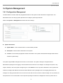
3.4 System Management
3.4.1 Configuration Management
The administrator can later obtain the geographical location of the system via the information configured here. The
administrator also can change system password and configure system login methods.
Please click System -> Management and follow the below settings.
System Information
System Name : Enter a desired name or use the default provided.
Description : Denote further information of the system.
Location : Enter related geographical location information of the system; administrator/manager will be able to
locate the system easily.
The system supports two management accounts, root and admin. The system manager is assigned with full
administrative privileges when logging in with the root account where the root manager can manage the system in any
respect. However, when the system manager logs in via the admin account, only basic maintenance can be performed.
Therefore, manager with different accounts will have different levels of privileges such as changing passwords; root
manager can change passwords for both root account and admin account, however, admin manager can only maintain its
own password. For more information on the respective privileges of these two management accounts, please refer to
42
User Manual
Air Force One 5
Appendix C. System Manager Privileges.
Root Password : The root manager can change its respective password. Enter the new password, and then verify
the new password in the Check New Password filed. Click Save button to activate the new password.
New Password : Please input the new password of administrator.
Check New Password : Please input again the new password of administrator.
Admin Password : The admin manager can change its respective password. Enter the new password, and then
verify the new password in the Check New Password filed. Click Save button to activate the new password.
New Password : Please input the new password of administrator.
Check New Password : Please input again the new password of administrator.
Admin Login Methods : The root manager can enable or disable system login methods, it can also change services
port. Click Save button to activate the admin login methods.
Enable HTTP : Select Enable HTTP to activate HTTP Service
HTTP Port : Please input 1 ~ 65535 value to set HTTP Port; default value is 80
Enable HTTPS : Select Enable HTTPS to activate HTTPS Service
HTTPS Port : Please input 1 ~ 65535 value to set HTTPS Port; default value is 443
If you already have an SSL Certificate, please click “UploadKey” button to select the file and upload it.
Enable Telnet : Select Enable Telnet to activate Telnet Service
Telnet Port : Please input 1 ~ 65535 value to set Telnet Port; default value is 23
Enable SSH : Select Enable SSH to activate SSH Service
SSH Port : Please input 1 ~ 65535 value to set SSH Port; default value is 22
Click “GenerateKey” button to generate RSA private key. The “Display the host key footprint” gray blank will be
show content of RSA key.
Change these settings as described here and click Save button to save your changes. Click Reboot button to activate
your changes
43
User Manual
Air Force One 5
Without a valid certificate, users may encounter the following problem in IE7 when they try to access system's WMI
(https://192.168.2.254). There will be a “Certificate Error”, because the browser treats system as an illegal website.
Click “Continue to this website” to access the system's WMI. The system's Overview page will appear.
44
User Manual
Air Force One 5
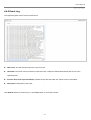
3.4.2 Configure System Time
System time can be configured via this page where manual setting and NTP server configuration are both supported.
Please click on System -> Time Server and follow the below setting.
Local Time : Display the current time of the system.
NTP Client : Enable Network Time Protocol, NTP, to synchronize the system time with NTP server.
Default NTP Server : Select the NTP Server from the drop-down list.
Time Zone : Please set a time zone from where the accurate time can be supplied, (GMT+08:00) Taipei for
example.
Daylight saving time : Enable Daylight saving time from where the accurate time needed.
If the current time of the system is incorrect, please verify your network settings, like default Gateway and DNS
settings
Change these settings as described here and click Save button to save your changes. Click Reboot button to activate
your changes
45
User Manual
Air Force One 5
3.4.3 Configure UPnP
UPnP(Universal Plug and Play) is architecture for pervasive peer-to-peer network connectivity of PCs and intelligent
devices or appliances, particularly within the home. UPnP builds on Internet standards and technologies, such as TCP/IP,
HTTP, and XML, to enable these devices automatically connect with one another and work together to make networking –
particularly home networking – possible for more people. Default: Disable.
UPnP : Click “Enable” to activate UPnP Service or “Disable” to deactivate. The default is Disable.
Change these settings as described here and click Save button to save your changes. Click Reboot button to activate
your changes
For UPnP to work in Windows XP, the “Air Force One 5” must be available in “My Network Places”, as shown here: (your
specific model may vary)
If these devices are not available, you should verify that the correct components and services are loaded in Windows XP.
Please refer to Appendix D. Using UPnP on Windows XP
46
User Manual
Air Force One 5
47
User Manual
Air Force One 5
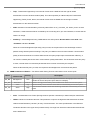
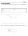
3.4.4 Configure SNMP Setup
SNMP is an application-layer protocol that provides a message format for communication between SNMP managers and
agents. By enabling SNMP function, the administrator can obtain the system information remotely.
Please click on System -> SNMP Setup and follow the below setting.
v2c : Check “Enable” button to activate SNMP v2c agent or unchecked to deactivate this function.
ro community : Enter the community strings that allows read-only access to the system's SNMP information.
rw community : Enter the community strings that allows read/write access to the system's SNMP information.
v3 :
Check “Enable” button to activate SNMP v3 agent or unchecked to deactivate this function. SNMPv3 supports
the highest available levels of security for SNMP communication.
48
User Manual
Air Force One 5
SNMP ro user : Enter the community strings that allows read-only access to the system's SNMP information.
SNMP ro password : Enter the password that allows read-only access to the system's SNMP information.
SNMP rw user : Enter the community strings that allows read/write access to the system's SNMP information.
SNMP rw password : Enter the password that allows read/write access to the system's SNMP information.
SNMP Trap : Events on cold start, interface up & down, and association & disassociation can be reported via this
function to an assigned server.
Community : Enter the community strings required by the remote host computer that will receive trap messages
or notices send by the system.
IP : Enter the IP address of the remote host computer that will receive the trap messages.
Change these settings as described here and click Save button to save your changes. Click Reboot button to activate
your changes
49
User Manual
Air Force One 5
3.4.5 Backup / Restore and Reset to Factory
Current settings on the system can be backed up, or previous backed up settings can be restored as well as resetting the
system back to factory default can be performed via this page.
Please click on Utilities -> Profile Setting and follow the below setting.
Save Settings to PC : Click Save button to save the current system settings to a local disk, i.e. the HDD of a local
computer or Compact Disc.
Load Settings from PC : Click Browse button to search for a previously saved backup file, and then click Upload
button to upload the settings; the system will then be configured to the same settings as specified by the backup file.
50
User Manual
Air Force One 5
Reset To Factory Default : Click Default button to load the factory default settings of "Air Force One 5", and then
Success Message page appears. Click Reboot button to set default configuration.
51
User Manual
Air Force One 5
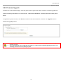
3.4.6 Firmware Upgrade
Firmware is the main software image, which the system needs to perform all tasks in real time. Firmware upgrades are
required for adding new features or to resolve bugs. It takes about 2 minutes to upload/ upgrade flash and be patient
please.
To upgrade the system firmware, click Browse to search for the new firmware file, and then click Upgrade button to
execute the upgrade process.
1.
2.
To prevent data loss during firmware upgrade, please back up the current settings before proceeding to
firmware upgrade.
During the upgrading. Do not interrupt the system, i.e. power on/off, during the upgrading process or the
restarting process as this may damage system.
52
User Manual
Air Force One 5
3.4.7 Network Utility
The administrator can diagnose the network connectivity via this function.
Please click on Utilities -> Network Utility and follow the below setting.
Ping : This utility will ping other devices on the network directly form the “Air Force One 5” device.
Ping utility should be used for the preliminary link quality and packet latency estimation between two network devices
using the ICMP packets. Packet loss statistics and latency time evaluation is provided after the test is completed.
Destination IP/Domain : Enter the desired domain name or IP address of the target device for diagnosis
purpose, i.e. www.google.com, and click ping button to proceed. The ping result will be shown in the Result field.
Count : Estimation is done after the number of ICMP packets; default is 5, maximum is 50.
Traceroute : Allows tracing the hops from the “Air Force One 5” device to a selected outgoing IP address. It should
be used for the finding the route taken by ICMP packets across the network to the destination host.
Destination Host : Specifies the Destination Host for the finding the route taken by ICMP packets across the
network.
MAX Hop : Specifies the maximum number of hops( max time-to-live value) traceroute will probe.
53
User Manual
Air Force One 5
The test is started using the Start button, click Stop button to stopped test
54
User Manual
Air Force One 5
3.4.8 Reboot
This function allows the administrator to safely restart the "Air Force One 5". Click Reboot to restart the system
immediately, and the whole process will take about three minutes to complete.
The Pop-up Restart window as displayed below appears during the rebooting period. If turning off the power is necessary,
please allow the restart process to be completed before turning off the system.
The System Overview page appears upon the completion of reboot.
55
User Manual
Air Force One 5
3.5 Observer Status
Information of current system settings can be over viewed via this page; statuses of Overview, Clients, WDS Status,
Extra Information and Event Log are displayed in this interface.
3.5.1 System Overview
Detailed information on System, Network, LAN Information and Wireless Information can be reviewed via this page.
System : Display the information of the system.
System Name : The name of the system.
Operating Mode : The mode currently in service.
Location : The reminding note on the geographical location of the system.
Description : The reminding note of the system.
Firmware Version : The current firmware version installed.
Firmware Date : The build time of the firmware installed.
Device Time : The current time of the system.
System Up Time : The time period that the system has been in service since last boot-up.
Network Information : Display the information of the Network.
56
User Manual
Air Force One 5
Mode : The current mode of the LAN port.
IP Address : The IP address of the LAN port.
IP Netmask : The IP netmask of the LAN port.
IP Gateway : The gateway IP address of the LAN port.
Primary DNS : The current primary DNS server of the system.
Secondary DNS : The current secondary DNS server of the system.
LAN Information : Display the detailed receive and transmit statistics of LAN interface.
MAC Address : The MAC address of the LAN port.
Receive bytes :The current receive bytes of the LAN port.
Receive packets : The current receive packets of the LAN port.
Transmit bytes : The current transmit bytes of the LAN port.
Transmit packets : The current transmit packets of the LAN port.
Wireless Information : Display the detailed receive and transmit statistics of Wireless interface.
MAC Address : The MAC address of the Wireless port.
Receive bytes :The current receive bytes of the Wireless port.
Receive packets : The current receive packets of the Wireless port.
Transmit bytes : The current transmit bytes of the Wireless port.
Transmit packets : The current transmit packets of the Wireless port.
57
User Manual
Air Force One 5
58
User Manual
Air Force One 5
3.5.2 Associated Clients Status
The administrator can obtain detailed Information such as VAP, ESSID, MAC Address, Status, and Security Type of all
associated clients via this page.
VAP Information : Display all Virtual AP's information
VAP : Indicate the system's Virtual AP
ESSID : Indicate the ESSID of the respective Virtual AP
Status : Indicate the Status of the respective Virtual AP
Security Type : Indicate the security type of the respective Virtual AP used.
Clients : Indicate the number of connection on the respective Virtual AP.
VAP Clients : Display all associated clients on each Virtual AP
MAC : indicate the MAC address of the respective client's association.
Signal Strength ANT0/ANT1 : Indicate the signal strength of the respective client's association.
Bandwidth : Indicate the channel bandwidth of the respective client's association.
Idle Time : Time period the associated client is inactive (units in seconds).
Connect Time : Time period the associated client is connection (units in seconds).
59
User Manual
Air Force One 5
60
User Manual
Air Force One 5
3.5.3 Show WDS Link Status
The administrator can obtain detailed Information such as MAC Address, Signal Strength of all WDS link via this page.
MAC : Display MAC address of WDS peer.
Signal Strength ANT0/ANT1 : Indicate the signal strength of the respective WDS linked.
Phy Mode : Indicate the phy mode
BandWidth : Indicate the channel bandwidth of the respective WDS linked.
of the respective WDS linked.
If Signal Strength ANT0/ANT1 display “no signal”, you need check WDS configuration. Verify MAC Address,
Channel and Security type is the same; also adjust system's antenna angle.
61
User Manual
Air Force One 5
3.5.4 Extra Information
The administrator can get current device usage statistics and status of the system components from drop-down list.
Show Netstat Information :
Select “NetStatus Information” on the drop-down list, the connection track list
should show-up, the list can be updated using the Refresh button.
NetStatus will show all connection track on the system, the information include Protocol, Live Time, Status ,
Source/Destination IP address and Port.
Show Route Information :
Select “Route Information” on the drop-down list, the route table should shown-up, the
list can be updated using the Refresh button.
“Air Force One 5” examines the destination IP address of each data packet traveling through the system and
chooses the appropriate interface to forward the packet to. The system choice depends on static routing rules –
entries, which are registered in system routing table. Static routes to specific hosts, networks or default gateway are
set up automatically according to the IP configuration of all the system's interfaces.
Show ARP Information :
Select “ARP Table Information” on the drop-down list, the ARP table should show-up,
the list can be updated using the Refresh button.
62
User Manual
Air Force One 5
ARP is used to associate each IP address to the unique hardware address (MAC) of the devices. It is important to
have unique IP
addresses for each
MAC or else there will
be ambiguous routes in the network.
Show Bridge Table Information :
Select “Bridge Table Information” on the drop-down list, the bridge table
should show-up, the list can be updated using the Refresh button.
Bridge table will show Bridge ID and STP's Status on the each Ethernet bridge and its attached interfaces, the Bridge
Port should be attached to some interfaces.
Show MAC Information :
Select “Bridge MACs Information” on the drop-down list, all the list of MAC address
should show up on the bridge table, the list can be updated using the Refresh button.
Bridge MACs shows to which Bridge Port the particular station is associated to - in other words from which Interface
(Ethernet or wireless ) the network device (defined by MAC address ) is reachable to the system while forwarding the
packets to that port only (thus saving a lot of redundant copies and transmits).
Ageing timer shows ageing time for each address entry (in seconds) - after particular time out, not having seen a
packet coming from a certain address, the bridge will delete that address from the Bridge Table.
63
User Manual
Air Force One 5
Show STP Information :
Select “Bridge STP Information” on the drop-down list, all the list of STP
information should
show up on the STP
table.
64
User Manual
Air Force One 5
3.5.5 Event Log
The reported system events can be reviewed here.
Date/ Time: The date and time when the event occurred.
Hostname: The name of the host which records the event. It helps the administrator identify the source of the
reported events.
Process name (with square brackets): Indicate the process with which the specific event is associated.
Description: Description of the event.
Click Refresh button to renew the log, or click Clear button to clear all the record.
65
User Manual
Air Force One 5
Chapter 4. WDS Mode Configuration
When WDS mode is activated, the system can be configured as a repeater or client bridge. This section provides
information in configuring the WDS mode with graphical illustrations. "Air Force One 5" provides functions as stated below
where they can be configured via a user-friendly web based interface.
Option
Functions
System
Wireless
Utilities
Status
Operating Mode
General Settings
Profiles Settings
System Overview
LAN
Advanced Settings
Firmware Upgrade
WDS Status
Management
WDS Setup
Network Utility
Extra Info
Reboot
Event Log
Time Server
UPnP
SNMP
Table 4-1: WDS Mode Functions
4.1 External Network Connection
4.1.1 Network Requirement
If you want to expand your wireless network through WDS link.
In this mode, the “Air Force One 5” (AFO-5) connected
directly to a wired LAN, and it cannot accept wireless clients to access wirelessly.
The first step is to get a Default Gateway IP Address from system manager and connect it to the LAN port of “Air Force
One 5”. Figure 4-1 shows Point to Point configuration
66
User Manual
Air Force One 5
Figure 4-1 Point to Point Configuration
67
User Manual
Air Force One 5
4.1.2 Configuration LAN IP
Here are the instructions for how to setup the local IP Address and Netmask.
Please click on System -> LAN and follow the below setting.
Mode : Check either “Static IP” or “Dynamic IP” button as desired to set up the system IP of LAN port .
Static IP : The administrator can manually setup the LAN IP address when static IP is available/ preferred.
IP Address : The IP address of the LAN port; default IP address is 192.168.2.254
IP Netmask : The Subnet mask of the LAN port; default Netmask is 255.255.255.0
IP Gateway : The default gateway of the LAN port; default Gateway is 192.168.2.1
Dynamic IP : This configuration type is applicable when the "Air Force One 5" is connected to a network with the
presence of a DHCP server; all related IP information will be provided by the DHCP server automatically.
Hostname : The Hostname of the LAN port
DNS : Check either “No Default DNS Server” or “Specify DNS Server IP” button as desired to set up the system DNS.
Primary : The IP address of the primary DNS server.
Secondary : The IP address of the secondary DNS server.
68
User Manual
Air Force One 5
802.1d Spanning Tree
The spanning tree network protocol provides a loop free topology for any bridged LAN. The Spanning Tree Protocol,
which is also referred to as STP, is defined in the IEEE Standard 802.1d.
Change these settings as described here and click Save button to save your changes. Click Reboot button to activate
your changes
69
User Manual
Air Force One 5
4.2 Wireless Network Expansion
The system manager can configure related wireless settings, General Settings, Advanced Settings, Virtual AP Setting,
Security Settings, and Access Control Settings.
4.2.1 General Setup
The administrator can change the data transmission, channel and output power settings for the system. Please click on
Wireless -> General Setup and follow the below setting.
MAC address : The MAC address of the Wireless interface is displayed here.
Band Mode : Select an appropriate wireless band; bands available are 801.11a or 802.11a/n mixed mode.
Client Isolation : Select Enable, all clients will be isolated from each other, that means all clients can not reach to
other clients.
Transmit Rate Control : Select the desired rate from the drop-down list; the options are auto or ranging from 1 to
54Mbps only for 802.11a mode.
Country : Select the desired country code from the drop-down list; the options are US, ETSI, JP and NONE.
Channel : The channel range will be changed by selecting different country code. Below depicts the channel range
for different Country.
Country
Channel
US
36, 40, 44, 48, 52, 56, 60, 64, 149, 153, 157, 161
ETSI
36, 40, 44, 48, 52, 56, 60, 64, 100, 104, 108, 112, 116, 120, 124, 128, 132, 136, 140
Japan
36, 40, 44, 48
NONE
36, 40, 44, 48, 52, 56, 60, 64, 100, 104, 108, 112, 116, 120, 124, 128, 132, 136, 140, 149, 153, 157, 161
70
User Manual
Air Force One 5
Tx Power : You can adjust the output power of the system to get the appropriate coverage for your wireless network.
Specify digit number between 1 to 100 (the unit is %) for your environment. If you are not sure which setting to
choose, then keep the default setting, 100%.
When Band Mode select in 802.11a/n mixed mode, the HT(High Throughput) settings should be shown-up
immediately.
HT TxStream/RxStream : Select 1 or 2 from the drop-down list
Operating Mode :
Mixed Mode : In this mode packets are transmitted with a preamble compatible with the legacy 802.11a/g, the
rest of the packet has a new format. In this mode the receiver shall be able to decode both the Mixed Mode
71
User Manual
Air Force One 5
packets and legacy packets.
Green Field : In this mode high throughput packets are transmitted without a legacy compatible part.
Channel Bandwidth : The "20/40” MHz option is usually best. The other option is available for special circumstances.
Guard Interval : Using “Auto” option can increase throughput. However, it can also increase error rate in some
installations, due to increased sensitivity to radio-frequency reflections. Select the option that works best for your
installation.
MCS : This parameter represents transmission rate. By default (Auto) the fastest possible transmission rate will be
selected. You have the option of selecting the speed if necessary.
Reverse Direction Grant(RDG) : Disable or enable reserve direction grant. Default is enabled.
Extension Channel : When 20/40 channel bandwidth has been chosen, you should select extension channel to get
higher throughput.
A-MSDU : Aggregated Mac Service Data Unit . Select Enable to allow aggregation for multiple MSDUs in one
MPDU Default is disabled.
Auto Block ACK : Disable or enable auto block ACK. Default is enabled.
Decline BA Request : Disable or enable decline BA request. Default is disabled.
Change these settings as described here and click Save button to save your changes. Click Reboot button to activate
your changes. The items in this page are for AP's RF general settings and will be applied to all VAPs.
72
User Manual
Air Force One 5
4.2.2 Advanced Setup
The administrator can change the RTS threshold and fragmentation threshold settings for the system. Please click on
Wireless -> Advanced Setup and follow the below setting.
Beacon Interval : Enter a value between 20 and 1024 msec. The default value is 100 milliseconds. The entered time
means how often the beacon signal transmission between the access point and the wireless network.
DTIM Interval : A DTIM is a countdown informing clients of the next window for listening to broadcast and multicast
messages. When the wireless router has buffered broadcast or multicast messages for associated clients, it sends
the next DTIM with a DTIM Interval value. Wireless clients detect the beacons and awaken to receive the broadcast
and multicast messages. The default value is 1. Valid settings are between 1 and 255.
Fragment Threshold : The value specifies the maximum size of packet allowed before data is fragmented into
multiple packets. Please use this value to tune the wireless connection if lots of retransmission happens. Enter a
value ranging from 256 to 2346.
RTS Threshold : Tuning the Request to Send, RTS threshold will help the system control its access to medium and
alleviate the hidden node problem. Enter a value ranging from 1 to 2347.
Short Preamble : The short preamble provides 56-bit Synchronization field to improve WLAN transmission efficiency.
Check Enable button for using Short Preamble, and Disable for using the Long Preamble, 128-bit Synchronization
field, option.
Short Slot : Enable or disable short slot. Default is enabled.
Tx Burst : Click Enable button to activate Tx Burst, and Disable to deactivate Tx Burst. Enable the Tx Burst can
73
User Manual
Air Force One 5
increase transmission throughput.
Pkt_Aggregate : Increase efficiency by aggregating multiple packets of application data into a single transmission
frame. In this way, 802.11n networks can send multiple data packets with the fixed overhead cost of just a single
frame.
IEEE802.11H : Select Enable to enable DFS(Dynamic Frequency Selection). Default is Enable. When a DFSenabled radio is operating on one of the following channels, the wireless device uses DFS to monitor the operating
frequency and switch to another frequency or reduce power as necessary:
DFS Channels
52, 56, 60, 64, 100, 104, 108, 112, 116, 120, 124, 128, 136, 140
The maximum legal transmit power is greater for some 5 GHz channels than for others. When the wireless device
randomly selects a 5 GHz channel on which power is restricted, the wireless device automatically reduces transmit
power to comply with power limits for that channel in that regulatory domain.
WMM Capable :
Select Enable, the configuration field of WMM parameters should be appears.
74
User Manual
Air Force One 5
When you enable WMM Capable, the “Tx Burst” will be Disabled automatically by system.
WMM Parameters of Access Point : This affects traffic flowing from the access point to the client station
Queue
Data Transmitted
AP to Clients
AC_BK
Background.
AC_BE
AC_VI
Best Effort
Video
AC_VO
Voice
Priority
Description
High throughput. Bulk data that requires maximum throughput and is not timesensitive is sent to this queue (FTP data, for example).
Medium Medium throughput and delay. Most traditional IP data is sent to this queue
High
Minimum delay. Time-sensitive video data is automatically sent to this queue
Time-sensitive data like VoIP and streaming media are automatically sent to this
High
queue
Low
Configuring QoS options consists of setting parameters on existing queues for different types of wireless traffic.
You can configure different minimum and maximum wait times for the transmission of packets in each queue
based on the requirements of the media being sent. Queues automatically provide minimum transmission delay
for Voice, Video, multimedia, and mission critical applications, and rely on best-effort parameters for traditional IP
data.
As an Example, time-sensitive Voice & Video, and multimedia are given effectively higher priority for transmission
(lower wait times for channel access), while other applications and traditional IP data which are less timesensitive but often more data-intensive are expected to tolerate longer wait times.
Aifsn : The Arbitration Inter-Frame Spacing Number specifies a wait time (in milliseconds) for data frames
CWmin : Minimum Contention Window. This parameter is input to the algorithm that determines the initial
random backoff wait time ("window") for retry of a transmission. The value specified here in the Minimum
Contention Window is the upper limit (in milliseconds) of a range from which the initial random backoff wait
time is determined.
CWmax : Maximum Contention Window. The value specified here in the Maximum Contention Window is
the upper limit (in milliseconds) for the doubling of the random backoff value. This doubling continues until
either the data frame is sent or the Maximum Contention Window size is reached. Once the Maximum
Contention Window size is reached, retries will continue until a maximum number of retries allowed is
reached. Valid values for the "cwmax" are 1, 3, 7, 15, 31, 63, 127, 255, 511, or 1024. The value for "cwmax"
must be higher than the value for "cwmin".
75
User Manual
Air Force One 5
Txop : Transmission Opportunity is an interval of time when a WME AP has the right to initiate
transmissions onto the wireless medium (WM). This value specifies (in milliseconds) the Transmission
Opportunity (TXOP) for AP; that is, the interval of time when the WMM AP has the right to initiate
transmissions on the wireless network.
ACM : Admission Control Mandatory, ACM only takes effect on AC_VI and AC_VO. When you do not click
Checkbox, it means that the ACM is controlled by the connecting AP. If you click Checkbox, it means that the
Client is in charge.
AckPolicy : Acknowledgment Policy, WMM defines two ACK policies: Normal ACK and No ACK. Click
“Checkbox” indicates “No ACK”
When the no acknowledgement (No ACK) policy is used, the recipient does not acknowledge received
packets during wireless packet exchange. This policy is suitable in the environment where communication
quality is fine and interference is weak. While the No ACK policy helps improve transmission efficiency, it
can cause increased packet loss when communication quality deteriorates. This is because when this policy
is used, a sender does not retransmit packets that have not been received by the recipient.
When the Normal ACK policy is used, the recipient acknowledges each received unicast packet.
WMM Parameters of Station : This affects traffic flowing from the client station to the access point.
Queue
Data Transmitted
Clients to AP
AC_BK
Background.
AC_BE
AC_VI
Best Effort
Video
AC_VO
Voice
Priority
Description
High throughput. Bulk data that requires maximum throughput and is not timesensitive is sent to this queue (FTP data, for example).
Medium Medium throughput and delay. Most traditional IP data is sent to this queue
High
Minimum delay. Time-sensitive video data is automatically sent to this queue
Time-sensitive data like VoIP and streaming media are automatically sent to this
High
queue
Low
Aifsn : The Arbitration Inter-Frame Spacing Number specifies a wait time (in milliseconds) for data frames
CWmin : Minimum Contention Window. This parameter is input to the algorithm that determines the initial
random backoff wait time ("window") for retry of a transmission. The value specified here in the Minimum
Contention Window is the upper limit (in milliseconds) of a range from which the initial random backoff wait
time is determined.
76
User Manual
Air Force One 5
CWmax : Maximum Contention Window. The value specified here in the Maximum Contention Window is
the upper limit (in milliseconds) for the doubling of the random backoff value. This doubling continues until
either the data frame is sent or the Maximum Contention Window size is reached. Once the Maximum
Contention Window size is reached, retries will continue until a maximum number of retries allowed is
reached. Valid values for the "cwmax" are 1, 3, 7, 15, 31, 63, 127, 255, 511, or 1024. The value for "cwmax"
must be higher than the value for "cwmin".
Txop : Transmission Opportunity is an interval of time when a WME AP has the right to initiate
transmissions onto the wireless medium (WM). This value specifies (in milliseconds) the Transmission
Opportunity (Txop) for AP; that is, the interval of time when the WMM AP has the right to initiate
transmissions on the wireless network.
ACM : Admission Control Mandatory, ACM only takes effect on AC_VI and AC_VO. When you do not click
Checkbox, it means that the ACM is controlled by the connecting AP. If you click Checkbox, it means that the
Client is in charge.
Change these settings as described here and click Save button to save your changes. Click Reboot button to activate
your changes. The items in this page are for AP's RF advanced settings and will be applied to all WDS link.
77
User Manual
Air Force One 5
4.2.3 WDS Setup
The administrator can create WDS Links via this page. Please click on Wireless -> WDS Setup and follow the below
setting.
Phy Mode : Select Phy mode for Multicast frames. The Phy mode can be selected in “CCK”, “OFDM”, “HTMIX” and
“GREENFIELD” from drop-down list. The “HTMIX” and “GREENFIELD” option is only for 802.11a/n mixed mode
Security Type : Configure an appropriate security type for the WDS link, the Security Type can be select in “Disable”,
“WEP”, “AES” or “TKIP” from drop-down list; the type needs to be the same as that configured on WDS peer.
WEP Key : Enter 5 / 13 ASCII or 10 / 26 HEX format WEP key value.
TKIP Key : Enter 8 to 63 ASCII or 64 HEX format TKIP key value.
AES Key : Enter 8 to 63 ASCII or 64 HEX format AES key value.
WDS MAC List
Enable : Click Enable button to create WDS link.
WDS Peer's MAC Address : Enter the MAC address of WDS peer.
Description : Description of WDS link.
The WDS link needs to be set at same Channel and Security Type.
78
User Manual
Air Force One 5
Change these settings as described here and click Save button to save your changes. Click Reboot button to activate
your changes
79
User Manual
Air Force One 5
4.3 System Management
4.3.1 Configuration Management
The administrator can later obtain the geographical location of the system via the information configured here. The
administrator also can change system password and configure system login methods.
Please click System -> Management and follow the below settings.
System Information
System Name : Enter a desired name or use the default provided.
Description : Denote further information of the system.
Location : Enter related geographical location information of the system; administrator/manager will be able to
locate the system easily.
The system supports two management accounts, root and admin. The system manager is assigned with full
administrative privileges when logging in with the root account where the root manager can manage the system in any
respect. However, when the system manager logs in via the admin account, only basic maintenance can be performed.
Therefore, manager with different accounts will have different levels of privileges such as changing passwords; root
manager can change passwords for both root account and admin account, however, admin manager can only maintain its
own password. For more information on the respective privileges of these two management accounts, please refer to
80
User Manual
Air Force One 5
Appendix C. System Manager Privileges.
Root Password : The root manager can change its respective password. Enter the new password, and then verify
the new password in the Check New Password filed. Click Save button to activate the new password.
New Password : Please input the new password of administrator.
Check New Password : Please input again the new password of administrator.
Admin Password : The admin manager can change its respective password. Enter the new password, and then
verify the new password in the Check New Password filed. Click Save button to activate the new password.
New Password : Please input the new password of administrator.
Check New Password : Please input again the new password of administrator.
Admin Login Methods : The root manager can enable or disable system login methods, it can also change services
port. Click Save button to activate the admin login methods.
Enable HTTP : Select Enable HTTP to activate HTTP Service
HTTP Port : Please input 1 ~ 65535 value to set HTTP Port; default value is 80
Enable HTTPS : Select Enable HTTPS to activate HTTPS Service
HTTPS Port : Please input 1 ~ 65535 value to set HTTPS Port; default value is 443
If you already have an SSL Certificate, please click “UploadKey” button to select the file and upload it.
Enable Telnet : Select Enable Telnet to activate Telnet Service
Telnet Port : Please input 1 ~ 65535 value to set Telnet Port; default value is 23
Enable SSH : Select Enable SSH to activate SSH Service
SSH Port : Please input 1 ~ 65535 value to set SSH Port; default value is 22
Click “GenerateKey” button to generate RSA private key. The “Display the host key footprint” gray blank will be
show content of RSA key.
Change these settings as described here and click Save button to save your changes. Click Reboot button to activate
your changes
81
User Manual
Air Force One 5
Without a valid certificate, users may encounter the following problem in IE7 when they try to access system's WMI
(https://192.168.2.254). There will be a “Certificate Error”, because the browser treats system as an illegal website.
Click “Continue to this website” to access the system's WMI. The system's Overview page will appear.
82
User Manual
Air Force One 5
4.3.2 Configure System Time
System time can be configured via this page where manual setting and NTP server configuration are both supported.
Please click on System -> Time Server and follow the below setting.
Local Time : Display the current time of the system.
NTP Client : Enable Network Time Protocol, NTP, to synchronize the system time with NTP server.
Default NTP Server : Select the NTP Server from the drop-down list.
Time Zone : Please set a time zone from where the accurate time can be supplied, (GMT+08:00) Taipei for
example.
Daylight saving time : Enable Daylight saving time from where the accurate time needed.
If the current time of the system is incorrect, please verify your network settings, like default Gateway and DNS
settings
Change these settings as described here and click Save button to save your changes. Click Reboot button to activate
your changes
83
User Manual
Air Force One 5
4.3.3 Configure UPnP
UPnP(Universal Plug and Play) is architecture for pervasive peer-to-peer network connectivity of PCs and intelligent
devices or appliances, particularly within the home. UPnP builds on Internet standards and technologies, such as TCP/IP,
HTTP, and XML, to enable these devices automatically connect with one another and work together to make networking –
particularly home networking – possible for more people. Default: Disable.
UPnP : Click “Enable” to activate UPnP Service or “Disable” to deactivate. The default is Disable.
Change these settings as described here and click Save button to save your changes. Click Reboot button to activate
your changes
For UPnP to work in Windows XP, the “Air Force One 5” must be available in “My Network Places”, as shown here: (your
specific model may vary)
If these devices are not available, you should verify that the correct components and services are loaded in Windows XP.
Please refer to Appendix D. Using UPnP on Windows XP
84
User Manual
Air Force One 5
4.3.4 Configure SNMP Setup
SNMP is an application-layer protocol that provides a message format for communication between SNMP managers and
agents. By enabling SNMP function, the administrator can obtain the system information remotely.
Please click on System -> SNMP Setup and follow the below setting.
v2c : Check “Enable” button to activate SNMP v2c agent or unchecked to deactivate this function.
ro community : Enter the community strings that allows read-only access to the system's SNMP information.
rw community : Enter the community strings that allows read/write access to the system's SNMP information.
v3 :
Check “Enable” button to activate SNMP v3 agent or unchecked to deactivate this function. SNMPv3 supports
the highest available levels of security for SNMP communication.
85
User Manual
Air Force One 5
SNMP ro user : Enter the community strings that allows read-only access to the system's SNMP information.
SNMP ro password : Enter the password that allows read-only access to the system's SNMP information.
SNMP rw user : Enter the community strings that allows read/write access to the system's SNMP information.
SNMP rw password : Enter the password that allows read/write access to the system's SNMP information.
SNMP Trap : Events on cold start, interface up & down, and association & disassociation can be reported via this
function to an assigned server.
Community : Enter the community strings required by the remote host computer that will receive trap messages
or notices send by the system.
IP : Enter the IP address of the remote host computer that will receive the trap messages.
Change these settings as described here and click Save button to save your changes. Click Reboot button to activate
your changes
86
User Manual
Air Force One 5
4.3.5 Backup / Restore and Reset to Factory
Current settings on the system can be backed up, or previous backed up settings can be restored as well as resetting the
system back to factory default can be performed via this page.
Please click on Utilities -> Profile Setting and follow the below setting.
Save Settings to PC : Click Save button to save the current system settings to a local disk, i.e. the HDD of a local
computer or Compact Disc.
Load Settings from PC : Click Browse button to search for a previously saved backup file, and then click Upload
button to upload the settings; the system will then be configured to the same settings as specified by the backup file.
87
User Manual
Air Force One 5
Reset To Factory Default : Click Default button to load the factory default settings of "Air Force One 5", and then
Success Message page appears. Click Reboot button to set default configuration.
88
User Manual
Air Force One 5
4.3.6 Firmware Upgrade
Firmware is the main software image, which the system needs to perform all tasks in real time. Firmware upgrades are
required for adding new features or to resolves bugs. It takes about 2 minutes to upload/ upgrade flash and be patient
please.
To upgrade the system firmware, click Browse to search for the new firmware file, and then click Upgrade button to
execute the upgrade process.
1.
2.
To prevent data loss during firmware upgrade, please back up the current settings before proceeding to
firmware upgrade.
During the upgrading. Do not interrupt the system, i.e. power on/off, during the upgrading process or the
restarting process as this may damage system.
89
User Manual
Air Force One 5
4.3.7 Network Utility
The administrator can diagnose the network connectivity via this function.
Please click on Utilities -> Network Utility and follow the below setting.
Ping : This utility will ping other devices on the network directly form the “Air Force One 5” device.
Ping utility should be used for the preliminary link quality and packet latency estimation between two network devices
using the ICMP packets. Packet loss statistics and latency time evaluation is provided after the test is completed.
Destination IP/Domain : Enter the desired domain name or IP address of the target device for diagnosis
purpose, i.e. www.google.com, and click ping button to proceed. The ping result will be shown in the Result field.
Count : Estimation is done after the number of ICMP packets; default is 5, maximum is 50.
Traceroute : Allows tracing the hops from the “Air Force One 5” device to a selected outgoing IP address. It should
be used for the finding the route taken by ICMP packets across the network to the destination host.
Destination Host : Specifies the Destination Host for the finding the route taken by ICMP packets across the
network.
MAX Hop : Specifies the maximum number of hops( max time-to-live value) traceroute will probe.
90
User Manual
Air Force One 5
The test is started using the Start button, click Stop button to stopped test
91
User Manual
Air Force One 5
4.3.8 Reboot
This function allows the administrator to safely restart the "Air Force One 5". Click Reboot to restart the system
immediately, and the whole process will take about three minutes to complete.
The Pop-up Restart window as displayed below appears during the rebooting period. If turning off the power is necessary,
please allow the restart process to be completed before turning off the system.
The System Overview page appears upon the completion of reboot.
92
User Manual
Air Force One 5
4.4 Observer Status
Information of current system settings can be over viewed via this page; statuses of Overview, WDS List, Extra
Information and Event Log are displayed in this interface.
4.4.1 System Overview
Detailed information on System, Network, LAN Information and Wireless Information can be reviewed via this page.
System : Display the information of the system.
System Name : The name of the system.
Operating Mode : The mode currently in service.
Location : The reminding note on the geographical location of the system.
Description : The reminding note of the system.
Firmware Version : The current firmware version installed.
Firmware Date : The build time of the firmware installed.
Device Time : The current time of the system.
System Up Time : The time period that the system has been in service since last boot-up.
Network Information : Display the information of the Network.
93
User Manual
Air Force One 5
Mode : The current mode of the LAN port.
IP Address : The IP address of the LAN port.
IP Netmask : The IP netmask of the LAN port.
IP Gateway : The gateway IP address of the LAN port.
Primary DNS : The current primary DNS server of the system.
Secondary DNS : The current secondary DNS server of the system.
LAN Information : Display the detailed receive and transmit statistics of LAN interface.
MAC Address : The MAC address of the LAN port.
Receive bytes :The current receive bytes of the LAN port.
Receive packets : The current receive packets of the LAN port.
Transmit bytes : The current transmit bytes of the LAN port.
Transmit packets : The current transmit packets of the LAN port.
Wireless Information : Display the detailed receive and transmit statistics of Wireless interface.
MAC Address : The MAC address of the Wireless port.
Receive bytes :The current receive bytes of the Wireless port.
Receive packets : The current receive packets of the Wireless port.
Transmit bytes : The current transmit bytes of the Wireless port.
Transmit packets : The current transmit packets of the Wireless port.
94
User Manual
Air Force One 5
4.4.2 WDS List
The administrator can obtain detailed Information such as MAC Address, Signal Strength of all WDS link via this page.
MAC : Display MAC address of WDS peer.
Signal Strength ANT0/ANT1 : Indicate the signal strength of the respective WDS linked.
Phy Mode : Indicate the phy mode
BandWidth : Indicate the channel bandwidth of the respective WDS linked.
of the respective WDS linked.
If Signal Strength ANT0/ANT1 display “no signal”, you need check WDS configuration. Verify MAC Address,
Channel and Security type is the same; also adjust system's antenna angle.
95
User Manual
Air Force One 5
4.4.3 Extra Information
The administrator can get current device usage statistics and status of the system components from drop-down list.
Show Netstat Information :
Select “NetStatus Information” on the drop-down list, the connection track list
should show-up, the list can be updated using the Refresh button.
NetStatus will show all connection track on the system, the information include Protocol , Live Time , Status ,
Source/Destination IP address and Port.
Show Route Information :
Select “Route Information” on the drop-down list, the route table should show-up, the
list can be updated using the Refresh button.
“Air Force One 5” examines the destination IP address of each data packet traveling through the system and
chooses the appropriate interface to forward the packet to. The system choice depends on static routing rules –
entries, which are registered in system routing table. Static routes to specific hosts, networks or default gateway are
set up automatically
according to the IP
configuration of all the
system's interfaces.
96
User Manual
Air Force One 5
Show ARP Information :
Select “ARP Table Information” on the drop-down list, the ARP table should show-up,
the list can be
updated using the
Refresh button.
ARP is used to associate each IP address to the unique hardware address (MAC) the devices. It is important to have
unique IP addresses for each MAC or else there will be ambiguous routes in the network.
Show Bridge Table Information :
Select “Bridge Table Information ” on the drop-down list, the bridge table should
show-up, the list can be updated using the Refresh button.
Bridge table will show Bridge ID and STP's Status on the each Ethernet bridge and its attached interfaces, the Bridge
Port should be attached to some interfaces.
Show MAC Information :
Select “Bridge MACs Information” on the drop-down list, all the list of MAC address
should show up on the bridge table, the list can be updated using the Refresh button.
Bridge MACs shows to which Bridge Port the particular station is associated to - in other words from which Interface
(Ethernet or wireless ) the network device (defined by MAC address ) is reachable to the system while forwarding the
packets to that port only (thus saving a lot of redundant copies and transmits).
97
User Manual
Air Force One 5
Ageing timer shows ageing time for each address entry (in seconds) - after particular time out, not having seen a
packet coming from a
certain address, the
bridge will delete that
address from the
Bridge Table.
Show STP Information :
Select “Bridge STP Information” on the drop-down list, all the list of
information should show up on the STP table.
98
STP
User Manual
Air Force One 5
4.4.4 Event Log
The reported system events can be reviewed here.
Date/ Time: The date and time when the event occurred.
Hostname: The name of the host which records the event. It helps the administrator identify the source of the
reported events.
Process name (with square brackets): Indicate the process with which the specific event is associated.
Description: Description of the event.
Click Refresh button to renew the log, or click Clear button to clear all the record.
99
User Manual
Air Force One 5
Chapter 5. CPE Mode Configuration
When CPE mode is activated, the system can be configured as a CPE. This section provides information in configuring
the CPE mode with graphical illustrations. "Air Force One 5" provides functions as stated below where they can be
configured via a user-friendly web based interface.
OPTION
Functions
System
Wireless
Advance
Utilities
Status
Operating Mode
General Setup
DMZ
Profiles Settings
System Overview
WAN
Wireless Profile
IP Filter Setup
Firmware Upgrade
Station Statistics
LAN
Site Survey
MAC Filter Setup
Network Utility
Extra Info
DDNS Setup
Virtual Server
Reboot
Event Log
Management
QoS
Time Server
UPNP
SNMP
Table 5-1: CPE Mode Functions
5.1 External Network Connection
5.1.1 Network Requirement
It can be used as an Outdoor Customer Premises Equipment (CPE) to receive wireless signal over last mile applications,
helping WISPs deliver wireless broadband Internet service to new residential and business customers. In this mode, the
wireless interface of “Air Force One 5” (AFO-5) become WAN port, It is a gateway with NAT and DHCP Server functions.
The wired clients of AFO-5 are in the different subnet from Main Base Station and it does not accept wireless
connections from client devices.
The first step, you need to have one access point (Base Station) and connect it to Internet. Then, Connecting your PC/NB
to the LAN port of “Air Force One 5” , Figure 5-1 shows CPE mode configuration
100
User Manual
Air Force One 5
Figure 5-1 CPE mode configuration
101
User Manual
Air Force One 5
5.1.2 Configure WAN Setup
Here is instruction for how to setup the WAN. There are three connection types for the WAN port : Static IP, Dynamic IP
and PPPoE,
Please click on System -> WAN and follow the below setting.
On CPE mode, the WAN Port is Wireless interface.
Mode : Check “Static IP”, “Dynamic IP” and “PPPoE” button as desired to set up the system IP of WAN port.
Static IP : The administrator can manually setup the WAN IP address when static IP is available/ preferred.
IP Address : The IP address of the WAN port; default IP address is 192.168.1.254
IP Netmask : The Subnet mask of the WAN port; default Netmask is 255.255.255.0
IP Gateway : The default gateway of the WAN port; default Gateway is 192.168.1.1
Dynamic IP : This configuration type is applicable when the "Air Force One 5" is connected to a network with the
presence of a DHCP server; all related IP information will be provided by the DHCP server automatically. If the IP
Address is not assigned from DHCP server, the system needs to be manually connect to DHCP server, Please
go to “WAN Information” of the Overview page, click Release button to release IP address of WAN port, Renew
button to renew IP address through DHCP server.
102
User Manual
Air Force One 5
Hostname : The Hostname of the WAN port
PPPoE : This configuration type is applicable when the "Air Force One 5" is connected to a network with the
presence of a PPPoE server.
User Name : Enter User Name for PPPoE connection
Password : Enter Password for PPPoE connection
Reconnect Mode : There are three reconnect mode can be selected.
Always on – A connection to Internet is always maintained.
On Demand – A connection to Internet is made as needed.
If Time Server is enabled on “On Demand” mode, it indicated the connection to Internet is always
maintained
Manual – You have to open up the Web-based Management Interface and click the “Connect” button
manually any time on “WAN Information” of the Overview page that you wish to connect to the Internet.
Idle Time : The time of inactivity before disconnecting your PPPoE session. Enter an Idle Time (in minutes) to
define a maximum period of time for which the Internet connect is maintained during inactivity. If the connection
is inactive for longer than the defined Idle Time, then the connection will be dropped.
103
User Manual
Air Force One 5
MTU : MTU stands for Maximum Transmission Unit. For PPPoE connections, you may need to set the MTU
setting in order to work correctly with your ISP. Default is 1492 bytes.
DNS : Check either “No Default DNS Server” or “Specify DNS Server IP” button as desired to set up the system DNS.
Primary : The IP address of the primary DNS server.
Secondary : The IP address of the secondary DNS server.
MAC Clone : The MAC address is a 12-digit code assigned to a unique piece of hardware for identification, like a
social security number. Some ISPs require you to register a MAC address in order to access the Internet. If you do
not wish to re-register the MAC address with your ISP, you may assign the MAC address you have currently
registered with your ISP
to the system using the
MAC Address Clone
feature.
Keep Default MAC Address : Keep the default MAC address of WAN port on the system.
Clone MAC Address : If you want to clone the MAC address of the PC you are currently using go configure the
system, then click the Clone MAC Address button. The system will automatically detect your PC's MAC address.
The Clone MAC Address field will display MAC address of the PC you are connected with the system currently.
Manual MAC Address : Enter the MAC address registered with your ISP.
Change these settings as described here and click Save button to save your changes. Click Reboot button to activate
104
User Manual
Air Force One 5
your changes
105
User Manual
Air Force One 5
5.1.3 Configure DDNS Setup
Dynamic DNS allows you to make an assumed name as a dynamic IP address to a static hostname.
Please click on System -> DDNS Setup and follow the below setting.
Enabled: Select Enable for DDNS function, each time your IP address for WAN is changed, the information will be
updated to DDNS service provider automatically.
Service Provider: Select the correct Service Provider from the drop-down list, here included are
dyndns, dhs, ods
and tzo embedded in the "Air Force One 5".
Hostname: This field represents the Host Name you register to Dynamic-DNS service and expect to export to the
world.
User Name & Password: User Name and Password is used as an identity to login DDNS service.
Change these settings as described here and click Save button to save your changes. Click Reboot button to activate
your changes
106
User Manual
Air Force One 5
5.1.4 LAN Setup
Here are the instructions for how to setup the local IP Address and Netmask.
Please click on System -> LAN and follow the below setting.
LAN IP : The administrator can manually setup the LAN IP address.
IP Address : The IP address of the LAN port; default IP address is 192.168.2.254
IP Netmask : The Subnet mask of the LAN port; default Netmask is 255.255.255.0
802.1d Spanning Tree
The spanning tree network protocol provides a loop free topology for any bridged LAN. The Spanning Tree Protocol,
which is also referred to as STP, is defined in the IEEE Standard 802.1d.
DHCP Setup : Devices connected to the system can obtain an IP address automatically when this service is enabled.
107
User Manual
Air Force One 5
DHCP :
Start IP / End IP: Specify the range of IP addresses to be used by the DHCP server when assigning IP address
Check Enable button to activate this function or Disable to deactivate this service.
to clients. The default range IP address is 192.168.2.10 to 192.168.2.70, the netmask is 255.255.255.0
DNS1 IP :
DNS2 IP : Enter IP address of the second DNS server; this is optional.
WINS IP : Enter IP address of the Windows Internet Name Service (WINS) server; this is optional.
Domain : Enter the domain name for this network.
Lease Time : The IP addresses given out by the DHCP server will only be valid for the duration specified by
Enter IP address of the first DNS server; this field is required.
the lease time. Increasing the time ensure client operation without interruptions, but could introduce potential
conflicts. Lowering the lease time will avoid potential address conflicts, but might cause more interruptions to the
client while it will acquire new IP addresses from the DHCP server.
Change these settings as described here and click Save button to save your changes. Click Reboot button to activate
your changes
108
User Manual
Air Force One 5
5.2 Access Point Association
5.2.1 Configure Wireless General Setting
The administrator can change the data transmission, channel and output power settings for the system. Please click on
Wireless -> General Setup and follow the below setting.
Band Mode : Select an appropriate wireless band; bands available are 801.11aor 802.11a/n mixed mode.
Country : Select the desired country code from the drop-down list; the options are US, ETSI, JP and NONE.
Transmit Rate Control : Select the desired rate from the drop-down list; the options are auto or ranging from 1 to
54Mbps for 802.11a
Tx Power : You can adjust the output power of the system to get the appropriate coverage for your wireless network.
Specify digit number between 1 to 100 (the unit is %) for your environment. If you are not sure of which setting to
choose, then keep the default setting, 100%.
When Band Mode select in 802.11a/n mixed mode, the HT(High Throughput) Physical Mode and 11n Configuration
settings should be shown-up immediately.
109
User Manual
Air Force One 5
Operating Mode :
Mixed Mode : In this mode packets are transmitted with a preamble compatible with the legacy 802.11a/g, the rest of
the packet has a new format. In this mode the receiver shall be able to decode both the Mixed Mode packets
and legacy packets.
Green Field : In this mode high throughput packets are transmitted without a legacy compatible part.
Channel Bandwidth : The "Auto” MHz option is usually best. The other option is available for special circumstances.
Guard Interval : Using “Auto” option can increase throughput. However, it can also increase error rate in some
installations, due to increased sensitivity to radio-frequency reflections. Select the option that works best for your
installation.
MCS : This parameter represents transmission rate. By default (Auto) the fastest possible transmission rate will be
selected. You have the option of selecting the speed if necessary.
MPDU Enable : Check Enable button to activate this function, and Disable to deactivate.
A-MPDU : A-MPDU (Aggregated Mac Protocol Data Unit) allows the transmissions of multiple Ethernet frames to a
single location as burst of up to 64kbytes This is performed on the hardware itself. Select “Manual” to set “MPDU
Density”
MPDU Density : Minimum separation of MPDUs in an A-MPDU.
0
No Restriction
1
2
3
4
5
6
7
¼ µs ½ µs 1 µs 2 µs 4 µs 8 µs 16 µs
A-MSDU : Aggregated Mac Service Data Unit, A-MSDU. Select Enable to allows aggregation for multiple MSDUs in
one MPDU. Default is disabled.
110
User Manual
Air Force One 5
Change these settings as described here and click Save button to save your changes. Click Reboot button to activate
your changes.
111
User Manual
Air Force One 5
5.2.2 Wireless Environment Scanning
Access points located around the system can be found via the scan function. The administrator can then select a desired
AP to be associated with via this page.
Please click on Wireless -> Site Survey. Below depict an example for site survey.
SSID : Service Set ID of the AP or repeater found around the system.
BSSID : MAC address of the respective AP.
Signal : Indicate the signal strength of the respective AP.
Channel : The channel number currently used by the respective AP.
Security : Security type enabled by the respective AP.
Network Type : Network type enabled by the respective AP.
Select: Click “Select” to configure settings for associating with the respective AP.
When you click “Select” on Station Site Survey Table, the system will copy “ESSID” and “Security Type” to
Wireless Profile page. But, you also need setting some parameters (e.g. Profile Name or Security Key) on
Wireless Profile page. About Wireless Profile setting, please see next section.
112
User Manual
Air Force One 5
5.2.3 Create Wireless Profile
The administrator can configure station profiles via this page.
Please click on Wireless -> Wireless Profile and follow the below setting.
Profile Name : Create a profile name for the current wireless network connection. For different wireless network, set
different profiles for quick connection uses.
SSID : Service Set Identifier, which is unique name shared among all clients in a wireless network. It must be
identical with your wireless router or access point's SSID settings.
Fragment Threshold : The value specifies the maximum size of packet allowed before data is fragmented into
multiple packets. Please use this value to tune the wireless connection if lots of retransmission happens. Enter a
value ranging from 256 to 2346.
RTS Threshold : Tuning the Request to Send, RTS threshold will help the system control its access to medium and
alleviate the hidden node problem. Enter a value ranging from 1 to 2347.
Short Preamble : The short preamble provides 56-bit Synchronization field to improve WLAN transmission efficiency.
Check Enable button for using Short Preamble, and Disable for using the Long Preamble, 128-bit Synchronization
field, option.
Tx Burst : Click Enable button to activate Tx Burst, and Disable to deactivate Tx Burst. Enable the Tx Burst can
increase transmission throughput.
WMM Capable : Select Enable, the packets with QoS WMM will have higher priority.
113
User Manual
Air Force One 5
Security Type : Configure an appropriate security type for association, the Security Type can be select in “NONE”,
“OPEN”, “SHARED”, “WPA-PSK”, or “WPA2-PSK” from drop-down list; the type needs to be the same as that
associated access point.
OPEN / SHARED : OPEN and SHARED require the user to set a WEP key to exchange data.
Key Index : Select key index used to designate the WEP key during data transmission. 4 different WEP
keys can be configured at the same time, but only one is used. Effective key is set with a choice of WEP
Key 1, 2, 3, or 4.
WEP Key # : Enter HEX(10 or 26) or
ASCII(5 or 13) format WEP key value; the system support up to 4
sets of WEP keys.
WPA-PSK (or WPA2-PSK) : WPA (or WPA2) Algorithms, allows the system accessing the network by using the
WPA-PSK protected access.
Cipher Suite : Select the desired cipher suite from the drop-down list; the options are AES and TKIP
Pre-shared Key : Enter the information for pre-shared key; the key can be either entered as a 256-bit
114
User Manual
Air Force One 5
secret in 64 HEX digits format, or 8 to 63 ASCII characters.
Profile List : The user can manage the created profiles for home, work or public areas. Below depict an example for
Profile List
Click “”Edit” an exist profile on the Profile List. The field of System Configuration and Security Policy will display
profile's content. Edit profile's content and then click “Save” button to save the profile.
Click “Del” to remove profile.
Click and Select a profile from list, then click the “Connect” button to connecting to the wireless network with the
profile setting.
If you only click “Connect” button and does not click “Save” button. The selected profile would not be saved on
the Profile List
Change these settings as described here and click Save button to save your changes. Click Reboot button to activate
your changes
115
User Manual
Air Force One 5
5.3 System Management
5.3.1 Configuration Management
The administrator can later obtain the geographical location of the system via the information configured here. The
administrator also can change system password and configure system login methods.
Please click System -> Management and follow the below settings.
System Information
System Name : Enter a desired name or use the default provided.
Description : Denote further information of the system.
Location : Enter related geographical location information of the system; administrator/manager will be able to
locate the system easily.
The system supports two management accounts, root and admin. The system manager is assigned with full
administrative privileges when logging in with the root account where the root manager can manage the system in any
respect. However, when the system manager logs in via the admin account, only basic maintenance can be performed.
Therefore, manager with different accounts will have different levels of privileges such as changing passwords; root
manager can change passwords for both root account and admin account, however, admin manager can only maintain its
own password. For more information on the respective privileges of these two management accounts, please refer to
116
User Manual
Air Force One 5
Appendix C. System Manager Privileges.
Root Password : The root manager can change its respective password. Enter the new password, and then verify
the new password in the Check New Password filed. Click Save button to activate the new password.
New Password : Please input the new password of administrator.
Check New Password : Please input again the new password of administrator.
Admin Password : The admin manager can change its respective password. Enter the new password, and then
verify the new password in the Check New Password filed. Click Save button to activate the new password.
New Password : Please input the new password of administrator.
Check New Password : Please input again the new password of administrator.
Admin Login Methods : The root manager can enable or disable system login methods, it can also
change services port. Click Save button to activate the admin login methods.
Enable HTTP : Select Enable HTTP to activate HTTP Service
HTTP Port : Please input 1 ~ 65535 value to set HTTP Port; default value is 80
Enable HTTPS : Select Enable HTTPS to activate HTTPS Service
HTTPS Port : Please input 1 ~ 65535 value to set HTTPS Port; default value is 443
If you already have an SSL Certificate, please click “UploadKey” button to select the file and upload it.
Enable Telnet : Select Enable Telnet to activate Telnet Service
Telnet Port : Please input 1 ~ 65535 value to set Telnet Port; default value is 23
Enable SSH : Select Enable SSH to activate SSH Service
SSH Port : Please input 1 ~ 65535 value to set SSH Port; default value is 22
Click “GenerateKey” button to generate RSA private key. The “Display the host key footprint” gray blank will be
show content of RSA key.
Change these settings as described here and click Save button to save your changes. Click Reboot button to activate
your changes
117
User Manual
Air Force One 5
Without a valid certificate, users may encounter the following problem in IE7 when they try to access system's WMI
(https://192.168.2.254). There will be a “Certificate Error”, because the browser treats system as an illegal website.
Click “Continue to this website” to access the system's WMI. The system's Overview page will appear.
118
User Manual
Air Force One 5
5.3.2 Configure System Time
System time can be configured via this page where manual setting and NTP server configuration are both supported.
Please click on System -> Time Server and follow the below setting.
Local Time : Display the current time of the system.
NTP Client : Enable Network Time Protocol, NTP, to synchronize the system time with NTP server.
Default NTP Server : Select the NTP Server from the drop-down list.
Time Zone : Please set a time zone from where the accurate time can be supplied, (GMT+08:00) Taipei for
example.
Daylight saving time : Enable Daylight saving time from where the accurate time needed.
If the current time of the system is incorrect, please verify your network settings, like default Gateway and DNS
settings
Change these settings as described here and click Save button to save your changes. Click Reboot button to activate
your changes
119
User Manual
Air Force One 5
5.3.3 Configure UPnP
UPnP(Universal Plug and Play) is architecture for pervasive peer-to-peer network connectivity of PCs and intelligent
devices or appliances, particularly within the home. UPnP builds on Internet standards and technologies, such as TCP/IP,
HTTP, and XML, to enable these devices automatically connect with one another and work together to make networking –
particularly home networking – possible for more people. Default: Disable.
UPnP : Click “Enable” to activate UPnP Service or “Disable” to deactivate. The default is Disable.
Change these settings as described here and click Save button to save your changes. Click Reboot button to activate
your changes
For UPnP to work in Windows XP, the “Air Force One 5” must be available in “My Network Places”, as shown here: (your
specific model may vary)
If these devices are not available, you should verify that the correct components and services are loaded in Windows XP.
Please refer to Appendix D. Using UPnP on Windows XP
120
User Manual
Air Force One 5
5.3.4 Configure SNMP Setup
SNMP is an application-layer protocol that provides a message format for communication between SNMP managers and
agents. By enabling SNMP function, the administrator can obtain the system information remotely.
Please click on System -> SNMP Setup and follow the below setting.
v2c : Check “Enable” button to activate SNMP v2c agent or unchecked to deactivate this function.
ro community : Enter the community strings that allows read-only access to the system's SNMP information.
rw community : Enter the community strings that allows read/write access to the system's SNMP information.
v3 :
Check “Enable” button to activate SNMP v3 agent or unchecked to deactivate this function. SNMPv3 supports
the highest available levels of security for SNMP communication.
121
User Manual
Air Force One 5
SNMP ro user : Enter the community strings that allows read-only access to the system's SNMP information.
SNMP ro password : Enter the password that allows read-only access to the system's SNMP information.
SNMP rw user : Enter the community strings that allows read/write access to the system's SNMP information.
SNMP rw password : Enter the password that allows read/write access to the system's SNMP information.
SNMP Trap : Events on cold start, interface up & down, and association & disassociation can be reported via this
function to an assigned server.
Community : Enter the community strings required by the remote host computer that will receive trap messages
or notices send by the system.
IP : Enter the IP address of the remote host computer that will receive the trap messages.
Change these settings as described here and click Save button to save your changes. Click Reboot button to activate
your changes
122
User Manual
Air Force One 5
5.3.5 Backup / Restore and Reset to Factory
Current settings on the system can be backed up, or previous backed up settings can be restored as well as resetting the
system back to factory default can be performed via this page.
Please click on Utilities -> Profile Setting and follow the below setting.
Save Settings to PC : Click Save button to save the current system settings to a local disk, i.e. the HDD of a local
computer or Compact Disc.
Load Settings from PC : Click Browse button to search for a previously saved backup file, and then click Upload
button to upload the settings; the system will then be configured to the same settings as specified by the backup file.
123
User Manual
Air Force One 5
Reset To Factory Default : Click Default button to load the factory default settings of "Air Force One 5", and then
Success Message page appears. Click Reboot button to set default configuration.
124
User Manual
Air Force One 5
5.3.6 Firmware Upgrade
Firmware is the main software image, which the system needs to perform all tasks in real time. Firmware upgrades are
required for adding new features or to resolves bugs. It takes about 2 minutes to upload/ upgrade flash and be patient
please.
To upgrade the system firmware, click Browse to search for the new firmware file, and then click Upgrade button to
execute the upgrade process.
1.
2.
To prevent data loss during firmware upgrade, please back up the current settings before proceeding to
firmware upgrade.
During the upgrading. Do not interrupt the system, i.e. power on/off, during the upgrading process or the
restarting process as this may damage system.
125
User Manual
Air Force One 5
5.3.7 Network Utility
The administrator can diagnose the network connectivity via this function.
Please click on Utilities -> Network Utility and follow the below setting.
Ping : This utility will ping other devices on the network directly form the “Air Force One 5” device.
Ping utility should be used for the preliminary link quality and packet latency estimation between two network devices
using the ICMP packets. Packet loss statistics and latency time evaluation is provided after the test is completed.
Destination IP/Domain : Enter the desired domain name or IP address of the target device for diagnosis
purpose, i.e. www.google.com, and click ping button to proceed. The ping result will be shown in the Result field.
Count : Estimation is done after the number of ICMP packets; default is 5, maximum is 50.
Traceroute : Allows tracing the hops from the “Air Force One 5” device to a selected outgoing IP
address. It should be used for the finding the route taken by ICMP packets across the network to the destination host.
Destination Host : Specifies the Destination Host for the finding the route taken by ICMP packets across the
network.
MAX Hop : Specifies the maximum number of hops( max time-to-live value) traceroute will probe.
126
User Manual
Air Force One 5
The test is started using the Start button, click Stop button to stopped test
127
User Manual
Air Force One 5
5.3.8 Reboot
This function allows the administrator to safely restart the "Air Force One 5". Click Reboot to restart the system
immediately, and the whole process will take about three minutes to complete.
The Pop-up Restart window as displayed below appears during the rebooting period. If turning off the power is necessary,
please allow the restart process to be completed before turning off the system.
The System Overview page appears upon the completion of reboot.
128
User Manual
Air Force One 5
5.4 Restrain Users
5.4.1 IP Filter Setup
IP filters deny or allow the use of specific protocols through the system's Wire (LAN) and Wireless (WAN) ports, and IP
Address filters allow or deny the forwarding of unicast or multicast packets either sent from or addressed to specific IP
Address. You can create a traffic to all addresses except those you specify. You can apply the filters
you create to
either or both Ethernet and radio ports and to either or both incoming and through packets. The administrator can set IP
Filter via this page,
Please click on Advance -> IP Filter Setup and follow the below setting.
Source Address/Mask : Enter the desired source IP address and netmask; the mask must be a plain number, i.e.
192.168.2.10/32
Source Port : The source port(s) required for this rule. A single port may be given, or a range may be given as
start:end , which will match all ports from start to end, inclusive.
Destination Address/Mask : Enter the desired destination IP address and netmask; the mask must be a plain
number, i.e. 192.168.1.10/32
Destination Port : The destination port(s) required for this rule. A single port may be given, or a range may be given
as start:end , which will match all ports from start to end, inclusive.
In/Out : This option used for specialized packet alteration. The system support In (INPUT : for packets coming into
the interface itself) or Out (FORWARD : for altering packets being routed through the interface)
129
User Manual
Air Force One 5
Protocol : This option allows you to select protocol type. The system support TCP, UDP or ICMP.
Listen : Enable Yes to match TCP packets only with the SYN flag.
Active : Enter Deny to DROP specialized packet; Pass to ACCET the specialized packet
Side : Select specified interface where filtering of the incoming /passing-through packets are processed.
When matching rule is on the list, it will follow rule. No matching rule is on the list, it will accept
Click “Add” button to add IP filter rule to List. There are 20 rules maximum allowed in this IP Filter List. All rules can be
edited or removed on the List. Click Reboot button to activate your changes.
When you create rules on the IP Filter List, the previous rules have higher priority. If you want only one IP address
accessing the system by telnet service from your network’s subnet, and other IP address unable to use telnet access to
the system. Below depict the examples for explaining priority of IP Filter setup.
Example 1 : On this setting, there is only IP address 192.168.2.2 able use telnet access to system from LAN port.
Source
Destination
Rule
IP/Mask
Port
IP/Mask
Port
In/Out
Protocol
Listen
Action
Side
1
192.168.2.2/32
192.2.254/32
80
In
TCP
n
Deny
LAN
2
192.168.2.0/24
192.168.2.254/32
80
In
TCP
n
Deny
LAN
Example 2 : On this setting, all of IP address 192.168.2.0 unable use telnet access to system from LAN port.
Because rule 1's priority is higher than rule 2
Source
Destination
Rule
IP/Mask
Port
IP/Mask
Port
In/Out
Protocol
Listen
Action
Side
1
192.168.2.0/24
192.168.2.254/32
80
In
TCP
n
Deny
LAN
2
192.168.2.2/32
192.2.254/32
80
In
TCP
n
Deny
LAN
130
User Manual
Air Force One 5
131
User Manual
Air Force One 5
5.4.2 MAC Filter Setup
MAC address filters allow or deny the forwarding of unicast and multicast packets either sent from or addressed to
specific MAC addresses. You can create a filter that passes traffic to all MAC address except those you specify, or you
can create a filter that blocks traffic to all MAC addresses except those you specify. The administrator can set MAC Filter
via this page,
Please click on Advance -> MAC Filter Setup and follow the below setting.
Action : Select the desired access control rule from the drop-down list; the options are “Disabled”, “Deny List MAC”
and “Allow List MAC”. Click “Save” button to save Action setting.
There are two ways to set the Access Control List :
Action is set to Deny List MAC.
The MAC address in the MAC Filter List will be denied access to WAN port and all the remaining MAC will be
granted
Action is set to Allow List MAC.
The MAC address in the MAC Filter List will be allowed access to WAN port and all the remaining MAC will be
denied
MAC Address : Enter MAC address in this field. The acceptable format are xxxxxxxxxxxx or xx:xx:xx:xx:xx:xx 12 hex
digit number.
Click “Add” button to add MAC filter rule to List. There are 20 rules maximum allowed in this MAC Filter List. All rules can
132
User Manual
Air Force One 5
be removed on the List. Click Reboot button to activate your changes.
133
User Manual
Air Force One 5
5.4.3 QoS Setup
Quality of Service (QoS) refers to both a network's ability to deliver data with minimum delay,
and the networking
methods used to control the use of bandwidth. Without QoS, all traffic data is equally likely to be dropped when the
network is congested. This can cause a reduction in network performance and make the network inadequate for timecritical application such as video-on-demand.
A classifier groups traffic into data flows according to specific criteria such as the source
source port number, destination port number or incoming port
select traffic from the same protocol
address, destination address,
number. For example, you can configure a classifier to
port (such as FTP) to form a flow.
Rules : Use the rules to define the classifiers. After you define the rules, you can specify action to act upon the traffic
that matches the rules.
Comment : Enter a descriptive name for this rule for identifying purposes.
MAC Address : Enter MAC address in valid MAC address format(xx:xx:xx:xx:xx:xx) and click “Add” button to
add in the MAC group of each rule. Click “Remove” button can remove MAC address in the group of each rule.
There are 10 MAC address
maximum allowed in each rule.
Source / Destination IP : Specify source/ destination IP addresses range required for this rule. If you specify
134
User Manual
Air Force One 5
source IP addresses range from 192.168.1.1 to 192.168.2.254. The matches a range of source IP addresses
include every single IP address from the first to the last, so the example above includes everything from
192.168.1.1 to 192.168.2.254.
DSCP Class : Differentiated services code point, DSCP. Select Any or specify classify traffic from drop-down list.
The Per-Hop Behavior (PHB) is indicated by encoding a 6-bit value—called the Differentiated Services Code
Point (DSCP)—into the 8-bit Differentiated Services (DS) field of the IP packet header. Below depicts class for
DSCP.
BE : Default PHB, which is typically best-effort traffic
EF : Expedited Forwarding PHB, dedicated to low-loss, low-latency traffic
AF : Aaaured Forwarding PHB, which gives assurance of delivery under conditions. The AF behavior group
defines four separate AF classes. Within each class, packets are given a drop precedence (high, medium or
low). The combination of classes and drop precedence yields twelve separate DSCP encodings from AF11
through AF43 (see table)
DROP Precedence
Class 1
Class 2
Class 3
Class 4
Low Drop
AF11
AF21
AF31
AF41
Medium Drop
AF12
AF22
AF32
AF42
High Drop
AF13
AF23
AF33
AF43
Protocol : Select Any or specify protocol from drop-down list. When you select ICMP or Layer 7 Application ,
the Source/ Destination Port can not used.
Source Port : Specify source port range required for this rule
Destination Port : Specify destination port range required for this rule
Action : After configuring rule, a policy rule ensures that a traffic flow gets the requested treatment in the network.
Remark DSCP : Specify a new DSCP class, if you want to replace or remark the DSCP
Bandwidth : Click “Enable” to activate function, and click “Disable” to deactivate function
Upload / Download : Specify the bandwidth in kilobit per second (Kbps). Enter a number between 8 to 8192,
default upload is 128 Kbps, download is 1024 Kbps.
135
User Manual
Air Force One 5
Click “Add” button to add QoS rule to List. There are 10 rules maximum allowed in this QoS List. All rules can be removed
or edited on the List. Click Reboot button to activate your changes.
When you create rules on the QoS List, the previous rules have higher priority. . Below depict the examples for explaining
priority of QoS setup.
Example 1 : On this setting, the FTP has 1024 Kbps upload and 8196 Kbps download on 192.168.2.10. The
other protocol only can use 512 Kbps bandwidth on each IP address. Because rule 1's
priority is higher than
rule 2
Rule
Source IP
1
192.168.2.10
Destination IP
2
DSCP
Protocol
Remark DSCP
Bandwidth (Up/Down)
ANY
FTP
NO
1024/8196
ANY
ANY
NO
512/512
Example 2 : On this setting, the FTP has 512 Kbps upload and 512 Kbps download on 192.168.2.10 Because
rule 1's
Rule
priority is higher than rule 2
Source IP
Destination IP
1
2
192.168.2.10
DSCP
Protocol
Remark DSCP
Bandwidth (Up/Down)
ANY
ANY
NO
512/512
ANY
FTP
NO
1024/8196
5.5 Internal Service Sharing
5.5.1 DMZ
The Demilitarized zone (DMZ) can be enabled and used as a place where services can be placed such as Web Servers,
Proxy Servers, and E-mail Servers, these services can still serve the local network and at the same time isolate it for
additional security. DMZ is commonly used with the NAT functionality as an alternative for the Virtual Server (IP / Port
Forwarding) while making all the ports of the host network devices visible from the external network side. Please click on
Advance -> DMZ and follow the below setting.
136
User Manual
Air Force One 5
DMZ : Check Enable button to activate this function, and Disable to deactivate.
IP Address : Enter the IP address of the computer or server to be used as DMZ host; only one DMZ host can be
activate at any time period.
Change these settings as described here and click Save button to save your changes. Click Reboot button to activate
your changes.
137
User Manual
Air Force One 5
5.5.2 Virtual Server (IP/ Port Forwarding)
A certain area in the network can be exposed to the Internet in a limited and controlled way for on-line game or video
conferencing via this page.
Please ensure the internal port to be used is not occupied by other applications.
Please click on Advance -> Virtual Server and follow the below setting.
Virtual Server : Check Enable button to activate this rule, and Disable to deactivate.
Description : Enter appropriate text to denote name of the Virtual server.
Private IP : The corresponding IP address of the LAN port used for the respective service. Enter the LAN IP address
of the assigned host.
Protocol Type : The communication protocol of session. Select an appropriate protocol type, either TCP or UDP
protocol.
Private Port : The private port(s) required for this rule. A single port may be given, or a range may be given as
start:end , which will match all ports from start to end, inclusive.
Public Port : The public port(s) required for this rule. A single port may be given, or a range may be given as
start:end , which will match all ports from start to end, inclusive.
The Private Port and Public Port can be different, but the port range needs to be the same.
example : Public Port is 10 to 20, the Private Port can be 30 to 40 or other 10 ports range.
138
User Manual
Air Force One 5
Click “Add” button to add Virtual Server rule to List. There are a maximum of 20 rules allowed in this List. All rules can be
edited or removed on the List. Click Reboot button to activate your changes.
139
User Manual
Air Force One 5
When you create rules on the Virtual List, the previous rules have higher priority. If you enable DMZ function. The Virtual
server has higher priority than DMZ. Below depict the examples for explaining priority of Virtual Server setup.
Example 1 : On this setting, all connections should be redirected to 192.168.2.12. But connections to port
20~80/tcp should be redirected to port 20~80 on 192.168.2.11, and connections to port 22/tcp should be
redirected to port 22 on 192.168.2.10
Rule
Protocol
Private IP
Private Port
Public Port
1
TCP
192.168.2.10
22
22
2
TCP
192.168.2.11
20:80
20:80
DMZ Enabled : 192.168.2.12
Example 2 : On this setting, On this setting, all connections should be redirected to 192.168.2.12. But
connections to port 20~80/tcp should be redirected to port 20~80 on 192.168.2.11. The rule 2 does not
availability.
Rule
Protocol
Private IP
Private Port
Public Port
1
TCP
192.168.2.11
20:80
20:80
2
TCP
192.168.2.10
22
22
DMZ Enabled : 192.168.2.12
140
User Manual
Air Force One 5
5.6 Observer Status
Information of current system settings can be over viewed via this page; statuses of Overview, Station Statistics, Extra
Info and Event Log are displayed in this interface.
5.6.1 Overview
Detailed information on System, WAN Information, LAN Information and DHCP Server Status can be reviewed via
this page.
System : Display the information of the system.
System Name : The name of the system.
Operating Mode : The mode currently in service.
Location : The reminding note on the geographical location of the system.
Description : The reminding note of the system.
Firmware Version : The current firmware version installed.
Firmware Date : The build time of the firmware installed.
Device Time : The current time of the system.
System Up Time : The time period that the system has been in service since last boot-up.
WAN Information : Display the information of the WAN interface.
141
User Manual
Air Force One 5
The WAN port specified Dynamic IP, the Release and Renew button will be show-up, click Release button to
release IP address of WAN port, Renew button to renew IP address through DHCP server.
The WAN port specified PPPoE, and the Connect and DisConnect button will be show up. Click “Connect” button
to assigned IP address from PPPoE server, “DisConnect” button to release IP address of WAN port.
Mode : The current mode of the WAN port.
Reconnect Mode : The current reconnect mode of the PPPoE.
MAC Address : The MAC address of the WAN port.
IP Address : The IP address of the WAN port.
IP Netmask : The IP netmask of the WAN port.
IP Gateway : The gateway IP address of the WAN port.
Primary DNS : The current primary DNS server of the system.
Secondary DNS : The current secondary DNS server of the system.
Receive bytes :The current receive bytes of the WAN port.
Receive packets : The current receive packets of the WAN port.
Transmit bytes : The current transmit bytes of the WAN port.
Transmit packets : The current transmit packets of the WAN port.
LAN Information : Display the detailed receive and transmit statistics of LAN interface.
MAC Address : The MAC address of the LAN port.
142
User Manual
Air Force One 5
IP Address : The IP address of the LAN port.
IP Netmask : The IP netmask of the LAN port.
Receive bytes :The current receive bytes of the LAN port.
Receive packets : The current receive packets of the
Transmit bytes : The current transmit bytes of the LAN port.
Transmit packets : The current transmit packets of the LAN port.
LAN port.
DHCP Server Status : The administrator can obtain DHCP client's IP/MAC address via this field. Below depicts an
example for enabled
DHCP server.
IP : The IP address assigned by DHCP server to the specific LAN device.
MAC address : The MAC address of the LAN device.
Lease Time : Shows how long the leased IP address will be valid and reserved for particular DHCP client.
143
User Manual
Air Force One 5
5.6.2 Station Statistics
The administrator can get Link information, Transmit and Receive Statistics via this page, Below depicts an example for
Station Statistics.
Link Status :
Status : Shows the current link status. It should be “Connected” or “Disconnected”.
ESSID : Shows the current SSID, which must be the same on the wireless client and AP in order for
communication to be established.
BSSID : Shows the associated BSSID, which can be used to identify the wireless access point.
Extra Info : Shows the current link status of extra information. It should be “Link is Up” or “Link is Down”,
Channel : Shows current channel and central channel, its corresponding frequency.
Link Speed(Mbps) : The data transfer speed adopted by this network. (measured in Mbits per second)
Throughput(Kbps) : Shows the current transmit rate(Tx) and receive rate(Rx). (measured in Kbits per second)
Link Quality : Shows the link quality of the system with an access point.
Signal Strength ANT0/ANT1 : Shows the wireless signal strength of the connection between system and an
access point.
HT Status :
144
User Manual
Air Force One 5
Channel BandWidth : Shows the current channel bandwidth used for communication. It should be “20” or “40”
Guard Interval :
MCS : Shows the current GI used for communication. It should be between 0 to 15 or 32.
Shows the current GI used for communication. It should be “short” or “long”.
Transmit Statistics
Frames Transmitted Successfully: The number of successfully transmitted frames.
Frames Transmitted Successfully Without Retry: The number of successfully transmitted frames without any
retry.
Frames Transmitted Successfully After Retry(s): The number of successfully transmitted frames with one or
more retries.
Frames Fail To Receive ACK After All Retries: The number of unsuccessfully transmitted frame with many
retries.
RTS Frames Successfully Receive CTS: The number of successful received CTS (Clear To Send) response
after this “Air Force One 5” sends out the RTS (Request To Send) message.
RTS Frames Fail To Receive CTS: The number of unsuccessful received CTS response after this “Air Force
One 5” sends out the RTS message.
Receive Statistics
Frames Received Successfully: The number of successful received frames.
Frames Received With CRC Error: The number of received frames with CRC (Cyclical Redundancy Checking)
error.
Frames Dropped Due To Out-of-Resource: The number of dropped frames.
Duplicate Frames Received: The number of duplicate frames.
145
User Manual
Air Force One 5
5.6.3 Extra Info
The administrator can get current device usage statistics and status of the system components from drop-down list.
Show Netstat Information :
Select “NetStatus Information” on the drop-down list, the connection track list
should show-up, the list can be updated using the Refresh button.
NetStatus will show all connection track on the system, the information include Protocol, Live Time, Status ,
Source/Destination IP address and Port.
Show Route Information :
Select “Route Information” on the drop-down list, the route table should show-up, the
list can be updated using the Refresh button.
“Air Force One 5” examines the destination IP address of each data packet traveling through the system and
chooses the appropriate interface to forward the packet to. The system choice depends on static routing rules –
entries, which are registered in system routing table. Static routes to specific hosts, networks or default gateway are
set up automatically according to the IP configuration of all the system's interfaces.
Show ARP Information :
Select “ARP Table Information” on the drop-down list, the ARP table should show-up,
the list can be updated using the Refresh button.
146
User Manual
Air Force One 5
ARP is used to associate each IP address to the unique hardware address (MAC) the devices. It is important to have
unique IP addresses for each MAC or else there will be ambiguous routes in the network.
Show Bridge Table Information :
Select “Bridge Table Information ” on the drop-down list, the bridge table should
show-up, the list can be updated using the Refresh button.
Bridge table will show Bridge ID and STP's Status on the each Ethernet bridge and its attached interfaces, the Bridge
Port should be
attached to some
interfaces.
Show MAC Information :
Select “Bridge MACs Information” on the drop-down list, all the list of MAC address
should show up on the bridge table, the list can be updated using the Refresh button.
Bridge MACs shows to which Bridge Port the particular station is associated to - in other words from which Interface
(Ethernet or wireless ) the network device (defined by MAC address ) is reachable to the system while forwarding the
packets to that port only (thus saving a lot of redundant copies and transmits).
Ageing timer shows ageing time for each address entry (in seconds) - after particular time out, not having seen a
packet coming from a certain address, the bridge will delete that address from the Bridge Table.
147
User Manual
Air Force One 5
Show STP Information :
Select “Bridge STP Information” on the drop-down list, all the list of STP information
should show up on the STP table.
148
User Manual
Air Force One 5
5.6.4 Event Log
The reported system events can be reviewed here.
Date/ Time: The date and time when the event occurred.
Hostname: The name of the host which records the event. It helps the administrator identify the source of the
reported events.
Process name (with square brackets): Indicate the process with which the specific event is associated.
Description: Description of the event.
Click Refresh button to renew the log, or click Clear button to clear all the record.
149
User Manual
Air Force One 5
Chapter 6. Universal Repeater Mode Configuration
When Universal Repeater mode is activated, the system can be configured as an Access Point and Client Station
simultaneously. This section provides information in configuring the Universal Repeater mode with graphical illustrations.
"Air Force One 5" provides functions as stated below where they can be configured via a user-friendly web based
interface.
Option
Functions
System
Wireless
Utilities
Status
Operating Mode
General Settings
Profiles Settings
System Overview
LAN
Advanced Settings
Firmware Upgrade
Clients
Management
Virtual AP
Network Utility
Remote AP
Time Server
Wireless Profile
Reboot
Extra Info
UPNP
Site Survey
Event Log
SNMP
Table 6-1: Universal Repeater Mode Functions
6.1 External Network Connection
6.1.1 Network Requirement
It can be used as an Outdoor Universal Repeater to receive wireless signal over last mile applications, and accepts
wireless connections from client devices. The wired clients of “Air Force One 5” are in the same subnet from Main Base
Station.
The first step, you need to have one access point (Base Station) and it connect to Internet. Then, Connecting your PC/NB
to the LAN port of “Air Force One 5”, Figure 6-1 shows Universal Repeater mode configuration
150
User Manual
Air Force One 5
Figure 6-1 Universal Repeater mode Configuration
When the AFO-5 configured as an Access Point and Client Station simultaneously, the Wireless General and
Advanced Setup also used simultaneously. But the Security Type can different. In the other word, the channel or
other settings will be the same between AFO-5 to Main Base Station and wireless client to AFO-5, but security
type can be different.
151
User Manual
Air Force One 5
6.1.2 Configuration LAN IP
Here are the instructions for how to setup the local IP Address and Netmask.
Please click on System -> LAN and follow the below setting.
Mode : Check either “Static IP” or “Dynamic IP” button as desired to set up the system IP of LAN port .
Static IP : The administrator can manually setup the LAN IP address when static IP is available/ preferred.
IP Address : The IP address of the LAN port; default IP address is 192.168.2.254
IP Netmask : The Subnet mask of the LAN port; default Netmask is 255.255.255.0
IP Gateway : The default gateway of the LAN port; default Gateway is 192.168.2.1
Dynamic IP : This configuration type is applicable when the "Air Force One 5" is connected to a network with the
presence of a DHCP server; all related IP information will be provided by the DHCP server automatically.
Hostname : The Hostname of the LAN port
DNS : Check either “No Default DNS Server” or “Specify DNS Server IP” button as desired to set up the system DNS.
Primary : The IP address of the primary DNS server.
Secondary : The IP address of the secondary DNS server.
152
User Manual
Air Force One 5
802.1d Spanning Tree
The spanning tree network protocol provides a loop free topology for any bridged LAN. The Spanning Tree Protocol,
which is also referred to as STP, is defined in the IEEE Standard 802.1d.
Change these settings as described here and click Save button to save your changes. Click Reboot button to activate
your changes
153
User Manual
Air Force One 5
6.2 Access Point Association
6.2.1 Configure Wireless General Setting
The administrator can change the data transmission, channel and output power settings for the system. Please click on
Wireless -> General Setup and follow the below setting.
Band Mode : Select an appropriate wireless band; bands available are 801.11aor 802.11a/n mixed mode.
Country : Select the desired country code from the drop-down list; the options are US, ETSI, JP and NONE.
Transmit Rate Control : Select the desired rate from the drop-down list; the options are auto or ranging from 1 to
54Mbps for 802.11a
Tx Power : You can adjust the output power of the system to get the appropriate coverage for your wireless network.
Specify digit number between 1 to 100 (the unit is %) for your environment. If you are not sure of which setting to
choose, then keep the default setting, 100%.
When Band Mode select in 802.11a/n mixed mode, the HT(High Throughput) Physical Mode and 11n Configuration
settings should be shown-up immediately.
154
User Manual
Air Force One 5
Operating Mode :
Mixed Mode : In this mode packets are transmitted with a preamble compatible with the legacy 802.11a/g, the
rest of the packet has a new format. In this mode the receiver shall be able to decode both the Mixed Mode
packets and legacy packets.
Green Field : In this mode high throughput packets are transmitted without a legacy compatible part.
Channel Bandwidth : The "Auto” MHz option is usually best. The other option is available for special circumstances.
Guard Interval : Using “Auto” option can increase throughput. However, it can also increase error rate in some
installations, due to increased sensitivity to radio-frequency reflections. Select the option that works best for your
installation.
MCS : This parameter represents transmission rate. By default (Auto) the fastest possible transmission rate will be
selected. You have the option of selecting the speed if necessary.
MPDU Enable : Check Enable button to activate this function, and Disable to deactivate.
A-MPDU : A-MPDU (Aggregated Mac Protocol Data Unit) allows the transmissions of multiple Ethernet frames to a
single location as burst of up to 64kbytes This is performed on the hardware itself. Select “Manual” to set “MPDU
Density”
MPDU Density : Minimum separation of MPDUs in an A-MPDU.
0
No Restriction
1
2
3
4
5
6
7
¼ µs ½ µs 1 µs 2 µs 4 µs 8 µs 16 µs
A-MSDU : Aggregated Mac Service Data Unit, A-MSDU. Select Enable to allow aggregation for multiple MSDUs in
one MPDU. Default is disabled.
155
User Manual
Air Force One 5
Change these settings as described here and click Save button to save your changes. Click Reboot button to activate
your changes.
156
User Manual
Air Force One 5
6.2.2 Wireless Advanced Setup
The administrator can change the RTS threshold and fragmentation threshold settings for the system. Please click on
Wireless -> Advanced Setup and follow the below setting.
Beacon Interval : Enter a value between 20 and 1024 msec. The default value is 100 milliseconds. The entered time
means how often the beacon signal transmission between the access point and the wireless network.
DTIM Interval : A DTIM is a countdown informing clients of the next window for listening to broadcast and multicast
messages. When the wireless router has buffered broadcast or multicast messages for associated clients, it sends
the next DTIM with a DTIM Interval value. Wireless clients detect the beacons and awaken to receive the broadcast
and multicast messages. The default value is 1. Valid settings are between 1 and 255.
Fragment Threshold : The value specifies the maximum size of packet allowed before data is fragmented into
multiple packets. Please use this value to tune the wireless connection if lots of retransmission happens. Enter a
value ranging from 256 to 2346.
RTS Threshold : Tuning the Request to Send, RTS threshold will help the system control its access to medium and
alleviate the hidden node problem. Enter a value ranging from 1 to 2347.
Short Preamble : The short preamble provides 56-bit Synchronization field to improve WLAN transmission efficiency.
Check Enable button for using Short Preamble, and Disable for using the Long Preamble, 128-bit Synchronization
field, option.
Short Slot : Enable or disable short slot. Default is enabled.
Tx Burst : Click Enable button to activate Tx Burst, and Disable to deactivate Tx Burst. Enable the Tx Burst can
157
User Manual
Air Force One 5
increase transmission throughput.
Pkt_Aggregate : Increase efficiency by aggregating multiple packets of application data into a single transmission
frame. In this way, 802.11n networks can send multiple data packets with the fixed overhead cost of just a single
frame.
IEEE802.11H : Select Enable to enable DFS(Dynamic Frequency Selection). Default is Enable. When a DFSenabled radio is operating on one of the following channels, the wireless device uses DFS to monitor the operating
frequency and switch to another frequency or reduce power as necessary:
DFS Channels
52, 56, 60, 64, 100, 104, 108, 112, 116, 120, 124, 128, 136, 140
The maximum legal transmit power is greater for some 5 GHz channels than for others. When the wireless device
randomly selects a 5 GHz channel on which power is restricted, the wireless device automatically reduces transmit
power to comply with power limits for that channel in that regulatory domain.
WMM Capable :
Select Enable, the configuration field of WMM parameters should appear.
158
User Manual
Air Force One 5
When you enable WMM Capable, the “Tx Burst” will be Disabled automatically by system.
WMM Parameters of Access Point : This affects traffic flowing from the access point to the client station
Queue
Data Transmitted
AP to Clients
AC_BK
Background.
AC_BE
AC_VI
Best Effort
Video
AC_VO
Voice
Priority
Description
High throughput. Bulk data that requires maximum throughput and is not timesensitive is sent to this queue (FTP data, for example).
Medium Medium throughput and delay. Most traditional IP data is sent to this queue
High
Minimum delay. Time-sensitive video data is automatically sent to this queue
Time-sensitive data like VoIP and streaming media are automatically sent to this
High
queue
Low
Configuring QoS options consists of setting parameters on existing queues for different types of wireless traffic.
You can configure different minimum and maximum wait times for the transmission of packets in each queue
based on the requirements of the media being sent. Queues automatically provide minimum transmission delay
for Voice, Video, multimedia, and mission critical applications, and rely on best-effort parameters for traditional IP
data.
As an Example, time-sensitive Voice & Video, and multimedia are given effectively higher priority for transmission
(lower wait times for channel access), while other applications and traditional IP data which are less timesensitive but often more data-intensive are expected to tolerate longer wait times.
Aifsn : The Arbitration Inter-Frame Spacing Number specifies a wait time (in milliseconds) for data frames
CWmin : Minimum Contention Window. This parameter is input to the algorithm that determines the initial
random backoff wait time ("window") for retry of a transmission. The value specified here in the Minimum
Contention Window is the upper limit (in milliseconds) of a range from which the initial random backoff wait
time is determined.
CWmax : Maximum Contention Window. The value specified here in the Maximum Contention Window is
the upper limit (in milliseconds) for the doubling of the random backoff value. This doubling continues until
either the data frame is sent or the Maximum Contention Window size is reached. Once the Maximum
Contention Window size is reached, retries will continue until a maximum number of retries allowed is
reached. Valid values for the "cwmax" are 1, 3, 7, 15, 31, 63, 127, 255, 511, or 1024. The value for "cwmax"
must be higher than the value for "cwmin".
159
User Manual
Air Force One 5
Txop : Transmission Opportunity is an interval of time when a WME AP has the right to initiate
transmissions onto the wireless medium (WM). This value specifies (in milliseconds) the Transmission
Opportunity (TXOP) for AP; that is, the interval of time when the WMM AP has the right to initiate
transmissions on the wireless network.
ACM : Admission Control Mandatory, ACM only takes effect on AC_VI and AC_VO. When you do not click
Checkbox, it means that the ACM is controlled by the connecting AP. If you click Checkbox, it means that the
Client is in charge.
AckPolicy : Acknowledgment Policy, WMM defines two ACK policies: Normal ACK and No ACK. Click
“Checkbox” indicates “No ACK”
When the no acknowledgement (No ACK) policy is used, the recipient does not acknowledge received
packets during wireless packet exchange. This policy is suitable in the environment where communication
quality is fine and interference is weak. While the No ACK policy helps improve transmission efficiency, it
can cause increased packet loss when communication quality deteriorates. This is because when this policy
is used, a sender does not retransmit packets that have not been received by the recipient.
When the Normal ACK policy is used, the recipient acknowledges each received unicast packet.
WMM Parameters of Station : This affects traffic flowing from the client station to the access point.
Queue
Data Transmitted
Clients to AP
AC_BK
Background.
AC_BE
AC_VI
Best Effort
Video
AC_VO
Voice
Priority
Description
High throughput. Bulk data that requires maximum throughput and is not timesensitive is sent to this queue (FTP data, for example).
Medium Medium throughput and delay. Most traditional IP data is sent to this queue
High
Minimum delay. Time-sensitive video data is automatically sent to this queue
Time-sensitive data like VoIP and streaming media are automatically sent to this
High
queue
Low
Aifsn : The Arbitration Inter-Frame Spacing Number specifies a wait time (in milliseconds) for data frames
CWmin : Minimum Contention Window. This parameter is input to the algorithm that determines the initial
random backoff wait time ("window") for retry of a transmission. The value specified here in the Minimum
Contention Window is the upper limit (in milliseconds) of a range from which the initial random backoff wait
time is determined.
160
User Manual
Air Force One 5
CWmax : Maximum Contention Window. The value specified here in the Maximum Contention Window is
the upper limit (in milliseconds) for the doubling of the random backoff value. This doubling continues until
either the data frame is sent or the Maximum Contention Window size is reached. Once the Maximum
Contention Window size is reached, retries will continue until a maximum number of retries allowed is
reached. Valid values for the "cwmax" are 1, 3, 7, 15, 31, 63, 127, 255, 511, or 1024. The value for "cwmax"
must be higher than the value for "cwmin".
Txop : Transmission Opportunity is an interval of time when a WME AP has the right to initiate
transmissions onto the wireless medium (WM). This value specifies (in milliseconds) the Transmission
Opportunity (Txop) for AP; that is, the interval of time when the WMM AP has the right to initiate
transmissions on the wireless network.
ACM : Admission Control Mandatory, ACM only takes effect on AC_VI and AC_VO. When you do not click
Checkbox, it means that the ACM is controlled by the connecting AP. If you click Checkbox, it means that the
Client is in charge.
Change these settings as described here and click Save button to save your changes. Click Reboot button to activate
your changes. The items in this page are for AP's RF advanced settings and will be applied to all VAPs.
161
User Manual
Air Force One 5
6.2.3 Wireless Environment Scanning
Access points located around the system can be found via the scan function. The administrator can then select a desired
AP to be associated with via this page.
Please click on Wireless -> Site Survey. Below depict an example for site survey.
SSID : Service Set ID of the AP or repeater found around the system.
BSSID : MAC address of the respective AP.
Signal : Indicate the signal strength of the respective AP.
Channel : The channel number currently used by the respective AP.
Security : Security type enabled by the respective AP.
Network Type : Network type enabled by the respective AP.
Select: Click “Select” to configure settings for associating with the respective AP.
When you click “Select” on Station Site Survey Table, the system will copy “ESSID” and “Security Type” to
Wireless Profile page. But, you also need setting some parameters (e.g. Profile Name or Security Key) on
Wireless Profile page. About Wireless Profile setting, please see next section.
162
User Manual
Air Force One 5
6.2.4 Create Wireless Profile
The administrator can configure station profiles via this page.
Please click on Wireless -> Wireless Profile and follow the below setting.
Profile Name : Create a profile name for the current wireless network connection. For different wireless network, set
different profiles for quick connection uses.
SSID : Service Set Identifier, which is unique name shared among all clients in a wireless network. It must be
identical with your wireless router or access point's SSID settings.
Security Type : Configure an appropriate security type for association, the Security Type can be select in “NONE”,
“OPEN”, “SHARED”, “WPA-PSK”, or “WPA2-PSK” from drop-down list; the type needs to be the same as that
associated access point.
OPEN / SHARED : OPEN and SHARED require the user to set a WEP key to exchange data.
Key Index : Select key index used to designate the WEP key during data transmission. 4 different WEP keys
163
User Manual
Air Force One 5
can be configured at the same time, but only one is used. Effective key is set with a choice of WEP Key 1, 2, 3,
or 4.
WEP Key # : Enter HEX(10 or 26) or
ASCII(5 or 13) format WEP key value; the system support up to 4 sets of
WEP keys.
WPA-PSK (or WPA2-PSK) : WPA (or WPA2) Algorithms, allows the system accessing the network by using the
WPA-PSK protected access.
Cipher Suite : Select the desired cipher suite from the drop-down list; the options are AES and TKIP
Pre-shared Key : Enter the information for pre-shared key; the key can be either entered as a 256-bit secret in
64 HEX digits format, or 8 to 63 ASCII characters.
Profile List : The user can manage the created profiles for home, work or public areas. Below depict an example for
Profile List
Click “”Edit” an exist profile on the Profile List. The field of System Configuration and Security Policy will display
profile's content. Edit profile's content and then click “Save” button to save the profile.
Click “Del” to remove profile.
164
User Manual
Air Force One 5
Click and Select a profile from list, then click the “Connect” button to connecting to the wireless network with the
profile setting.
If you only click “Connect” button and does not click “Save” button. The selected profile would not be saved on
the Profile List
Change these settings as described here and click Save button to save your changes. Click Reboot button to activate
your changes
165
User Manual
Air Force One 5
6.3 Wireless LAN Network Creation
The system manager can configure related wireless settings, Virtual AP Setting, Security Settings, and Access
Control Settings.
When Universal Repeater mode is activated, the system can be configured as an Access Point and Client Station
simultaneously.
6.3.1 Create Virtual AP
The “Air Force One 5” support broadcasting multiple SSIDs, allowing the creation of Virtual Access Points, partitioning a
single physical access point into 8 logical access points, each of which can have a different set of security, VLAN tag(ID)
and network settings. Figure 6-2 shows multiple SSIDs with different security type and vlan settings.
Figure 6-2 Multiple SSIDs with different Security Type and VLAN Tag
6.3.1.1 Virtual AP Overview
The administrator can view all of the Virtual AP's settings via this page.
Please click on Wireless -> Virtual AP Setup and the Virtual AP Overview Page appears.
166
User Manual
Air Force One 5
VAP : Indicate the system's Virtual AP
ESSID : Indicate the ESSID of the respective Virtual AP
Status : Indicate the Status of the respective Virtual AP
Security Type : Indicate the security type of the respective Virtual AP used.
MAC ACL : Indicate the MAC ACL of the respective Virtual AP used.
Edit : Click Edit button for configuring Virtual AP's settings, security type and ACL.
167
User Manual
Air Force One 5
6.3.1.2 Virtual AP Setup
For each Virtual AP, administrators can configure SSID, VLAN tag (ID), SSID broadcasting, Maximum number of client
associations, security type and Access Control List(ACL) settings.
Click Edit link on the VAP List, and then Virtual AP setup page appears.
Enable VAP :
SSID : Service Set ID, ESSID will determine the service type of a client which is assigned to the specified VAP. When
Click “Enable” to activate VAP or click “Disable” to deactivate this function
clients are browsing for available wireless networks, this is the SSID that will appear in the list.
Hidden SSID : Select this option to enable the SSID to broadcast in your network. When configuring the network, it is
suggested to enable this function but disable it when the configuration is complete. With this enabled, someone could
easily obtain the SSID information with the site survey software and get unauthorized access to a private network.
With this disabled, network security is enhanced and can prevent the SSID from being seen in the network.
Maximum Clients : You can set the number of wireless clients that can associate via a particular SSID, Enter
maximum number of clients to a desired number. For example, while the number of client is set to 5, only 5 clients
are allowed to connect with this VAP. The default value is 32
VLAN Tag(ID) : Virtual LAN, the system supports tagged VLAN. To enable VLAN function; valid values are from 1 to
4094. If your network uses VLANs, you can assign an SSID to VLAN1, and the access point groups client devices
using that SSID into VLAN1. This enables the separation of wireless applications based on security.
Security Type : Select the desired security type from the drop-down list; the options are Disable, WEP, WPA-PSK,
WPA2-PSK, WPA-Enterprise, WPA2-Enterprise and WEP 802.1X.
Disable : Data are unencrypted during transmission when this option is selected.
WEP : WEP, Wired Equivalent Privacy, is a data encryption mechanism based on a 64-bit or 128-bit shared key.
168
User Manual
Air Force One 5
Select WEP as the security type from the drop-down list as desired.
Authentication Method : Enable the desire option among OPEN, SHARED or WEPAUTO.
Key Index : Select key index used to designate the WEP key during data transmission. 4 different WEP
keys can be configured at the same time, but only one is used. Effective key is set with a choice of WEP
Key 1, 2, 3, or 4.
WEP Key # : Enter HEX(10 or 26) or
ASCII(5 or 13) format WEP key value; the system support up to 4
sets of WEP keys.
WPA-PSK (or WPA2-PSK) : WPA (or WPA2) Algorithms, allows the system accessing the network by using the
WPA-PSK protected access.
Cipher Suite : Check on the respective button to enable either AES or TKIP cipher suites; default is AES.
Pre-shared Key : Enter the information for pre-shared key; the key can be either entered as a 256-bit
secret in 64 HEX digits format, or 8 to 63 ASCII characters.
Group Key Update Period : This time interval for e-keying GTK (broadcast/multicast encryption keys) in
seconds. Enter the time-length required; the default time is 3600 seconds.
169
User Manual
Air Force One 5
WPA-Enterprise (or WPA2-Enterprise): The RADIUS authentication and encryption will be both enabled if this
is selected.
WPA General Settings :
•
Cipher Suite : Select the desired cipher suite from the drop-down list; the options are AES and TKIP
•
Group Key Update Period : This time interval for re-keying GTK (broadcast/ multicast encryption keys)
in seconds. Enter the time-length required; the default time is 3600 seconds.
•
PMK Cache Period : Pairwise Master Key, PMK. Set WPA2 PMKID cache timeout period, after time
out, the cached key will be deleted.
•
Pre-Authentication : Set WPA2 pre-authentication mode. This is used to speed up roaming before preauthenticating IEEE 802.1X/EAP part of the full RSN authentication and key handshake before actually
associating with a new AP. Default is disable.
RADIUS Server Settings :
•
IP Address : Enter the IP address of the Authentication RADIUS server.
•
Port : The port number used by Authentication RADIUS server. Use the default 1812 or enter port
170
User Manual
Air Force One 5
number specified.
•
Shared secret : The secret key for system to communicate with Authentication RADIUS server.
Support 8 to 64 characters.
•
Session Timeout : Amount of time before a client will be required to re-authenticate. The Session
Timeout unit is seconds and must be larger than 60 ; 0 is disable re-authenticate service.
WEP 802.1X : When WEP 802.1x Authentication is enabled, please refer to the following settings to complete
the configuration.
Radius Server Settings :
•
IP Address : Enter the IP address of the Authentication RADIUS server.
•
Port : The port number used by Authentication RADIUS server. Use the default 1812 or enter port
number specified.
•
Shared secret : The secret key for system to communicate with Authentication RADIUS server.
Support 8 to 64 characters.
•
Session Timeout : Amount of time before a client will be required to re-authenticate. The Session
Timeout unit is seconds and must be larger than 60 ; 0 is disable re-authenticate service.
171
User Manual
Air Force One 5
6.3.2 Black Wireless Clients
Continue 6.3.1.2 Virtual AP Setup section. For each Virtual AP setting, the administrator can allow or reject clients to
access each Virtual AP.
Access Control Type : Select the desired access control type from the drop-down list; the options are Disable,
Allow or Reject..
There are two ways to set the Access Control List :
Access Control Type is set to Allow.
The wireless clients in the “Enable” list which will be allowed access to the Access Point; in the other word, the
wireless clients in the “Disable” list will be denied access to the Access Point
Access Control Type is set to Reject.
The wireless clients in the “Enable” list which will denied access to the Access Point; in the other word, the wireless
clients in the “Disable” list will be granted access to the Access Point.
Add a station MAC : Enter MAC address in this field (e.g. aa:bb:cc:00:00:0a) and click “Add” button, then the MAC
address should be display on “Enable” list
172
User Manual
Air Force One 5
There are a maximum of 20 clients allowed in this MAC address list. The MAC addresses of the wireless clients can be
added and removed to the list using the Add and Remove buttons.
Click Reboot button to activate your changes
MAC Access Control is the weakest security approach. WPA or WPA2 security methods should be used when
possible.
173
User Manual
Air Force One 5
6.4 System Management
6.4.1 Configuration Management
The administrator can later obtain the geographical location of the system via the information configured here. The
administrator also can change system password and configure system login methods.
Please click System -> Management and follow the below settings.
System Information
System Name : Enter a desired name or use the default provided.
Description : Denote further information of the system.
Location : Enter related geographical location information of the system; administrator/manager will be able to
locate the system easily.
The system supports two management accounts, root and admin. The system manager is assigned with full
administrative privileges when logging in with the root account where the root manager can manage the system in any
respect. However, when the system manager logs in via the admin account, only basic maintenance can be performed.
Therefore, manager with different accounts will have different levels of privileges such as changing passwords; root
manager can change passwords for both root account and admin account, however, admin manager can only maintain its
own password. For more information on the respective privileges of these two management accounts, please refer to
174
User Manual
Air Force One 5
Appendix C. System Manager Privileges.
Root Password : The root manager can change its respective password. Enter the new password, and then verify
the new password in the Check New Password filed. Click Save button to activate the new password.
New Password : Please input the new password of administrator.
Check New Password : Please input again the new password of administrator.
Admin Password : The admin manager can change its respective password. Enter the new password, and then
verify the new password in the Check New Password filed. Click Save button to activate the new password.
New Password : Please input the new password of administrator.
Check New Password : Please input again the new password of administrator.
Admin Login Methods : The root manager can enable or disable system login methods, it can also change
services port. Click Save button to activate the admin login methods.
Enable HTTP : Select Enable HTTP to activate HTTP Service
HTTP Port : Please input 1 ~ 65535 value to set HTTP Port; default value is 80
Enable HTTPS : Select Enable HTTPS to activate HTTPS Service
HTTPS Port : Please input 1 ~ 65535 value to set HTTPS Port; default value is 443
If you already have an SSL Certificate, please click “UploadKey” button to select the file and upload it.
Enable Telnet : Select Enable Telnet to activate Telnet Service
Telnet Port : Please input 1 ~ 65535 value to set Telnet Port; default value is 23
Enable SSH : Select Enable SSH to activate SSH Service
SSH Port : Please input 1 ~ 65535 value to set SSH Port; default value is 22
Click “GenerateKey” button to generate RSA private key. The “Display the host key footprint” gray blank will be
show content of RSA key.
Change these settings as described here and click Save button to save your changes. Click Reboot button to activate
your changes
175
User Manual
Air Force One 5
Without a valid certificate, users may encounter the following problem in IE7 when they try to access system's WMI
(https://192.168.2.254). There will be a “Certificate Error”, because the browser treats system as an illegal website.
Click “Continue to this website” to access the system's WMI. The system's Overview page will appear.
176
User Manual
Air Force One 5
6.4.2 Configure System Time
System time can be configured via this page where manual setting and NTP server configuration are both supported.
Please click on System -> Time Server and follow the below setting.
Local Time : Display the current time of the system.
NTP Client : Enable Network Time Protocol, NTP, to synchronize the system time with NTP server.
Default NTP Server : Select the NTP Server from the drop-down list.
Time Zone : Please set a time zone from where the accurate time can be supplied, (GMT+08:00) Taipei for
example.
Daylight saving time : Enable Daylight saving time from where the accurate time needed.
If the current time of the system is incorrect, please verify your network settings, like default Gateway and DNS
settings
Change these settings as described here and click Save button to save your changes. Click Reboot button to activate
your changes
177
User Manual
Air Force One 5
6.4.3 Configure UPnP
UPnP(Universal Plug and Play) is architecture for pervasive peer-to-peer network connectivity of PCs and intelligent
devices or appliances, particularly within the home. UPnP builds on Internet standards and technologies, such as TCP/IP,
HTTP, and XML, to enable these devices automatically connect with one another and work together to make networking –
particularly home networking – possible for more people. Default: Disable.
UPnP : Click “Enable” to activate UPnP Service or “Disable” to deactivate. The default is Disable.
Change these settings as described here and click Save button to save your changes. Click Reboot button to activate
your changes
For UPnP to work in Windows XP, the “Air Force One 5” must be available in “My Network Places”, as shown here: (your
specific model may vary)
If these devices are not available, you should verify that the correct components and services are loaded in Windows XP.
Please refer to Appendix D. Using UPnP on Windows XP
178
User Manual
Air Force One 5
6.4.4 Configure SNMP Setup
SNMP is an application-layer protocol that provides a message format for communication between SNMP managers and
agents. By enabling SNMP function, the administrator can obtain the system information remotely.
Please click on System -> SNMP Setup and follow the below setting.
v2c : Check “Enable” button to activate SNMP v2c agent or unchecked to deactivate this function.
ro community : Enter the community strings that allows read-only access to the system's SNMP information.
rw community : Enter the community strings that allows read/write access to the system's SNMP information.
v3 :
Check “Enable” button to activate SNMP v3 agent or unchecked to deactivate this function. SNMPv3 supports
the highest available levels of security for SNMP communication.
179
User Manual
Air Force One 5
SNMP ro user : Enter the community strings that allows read-only access to the system's SNMP information.
SNMP ro password : Enter the password that allows read-only access to the system's SNMP information.
SNMP rw user : Enter the community strings that allows read/write access to the system's SNMP information.
SNMP rw password : Enter the password that allows read/write access to the system's SNMP information.
SNMP Trap : Events on cold start, interface up & down, and association & disassociation can be reported via this
function to an assigned server.
Community : Enter the community strings required by the remote host computer that will receive trap messages
or notices send by the system.
IP : Enter the IP address of the remote host computer that will receive the trap messages.
Change these settings as described here and click Save button to save your changes. Click Reboot button to activate
your changes
180
User Manual
Air Force One 5
6.4.5 Backup / Restore and Reset to Factory
Current settings on the system can be backed up, or previous backed up settings can be restored as well as resetting the
system back to factory default can be performed via this page.
Please click on Utilities -> Profile Setting and follow the below setting.
Save Settings to PC : Click Save button to save the current system settings to a local disk, i.e. the HDD of a local
computer or Compact Disc.
Load Settings from PC : Click Browse button to search for a previously saved backup file, and then click Upload
button to upload the settings; the system will then be configured to the same settings as specified by the backup file.
181
User Manual
Air Force One 5
Reset To Factory Default : Click Default button to load the factory default settings of "Air Force One 5", and then
Success Message page appears. Click Reboot button to set default configuration.
182
User Manual
Air Force One 5
6.4.6 Firmware Upgrade
Firmware is the main software image, which the system needs to perform all tasks in real time. Firmware upgrades are
required for adding new features or to resolves bugs. It takes about 2 minutes to upload/ upgrade flash and be patient
please.
To upgrade the system firmware, click Browse to search for the new firmware file, and then click Upgrade button to
execute the upgrade process.
1.
2.
To prevent data loss during firmware upgrade, please back up the current settings before proceeding to
firmware upgrade.
During the upgrading. Do not interrupt the system, i.e. power on/off, during the upgrading process or the
restarting process as this may damage system.
183
User Manual
Air Force One 5
6.4.7 Network Utility
The administrator can diagnose the network connectivity via this function.
Please click on Utilities -> Network Utility and follow the below setting.
Ping : This utility will ping other devices on the network directly form the “Air Force One 5” device.
Ping utility should be used for the preliminary link quality and packet latency estimation between two network devices
using the ICMP packets. Packet loss statistics and latency time evaluation is provided after the test is completed.
Destination IP/Domain : Enter the desired domain name or IP address of the target device for diagnosis
purpose, i.e. www.google.com, and click ping button to proceed. The ping result will be shown in the Result field.
Count : Estimation is done after the number of ICMP packets; default is 5, maximum is 50.
Traceroute : Allows tracing the hops from the “Air Force One 5” device to a selected outgoing IP address. It should
be used for the finding the route taken by ICMP packets across the network to the destination host.
Destination Host : Specifies the Destination Host for the finding the route taken by ICMP packets across the
network.
MAX Hop : Specifies the maximum number of hops( max time-to-live value) traceroute will probe.
184
User Manual
Air Force One 5
The test is started using the Start button, click Stop button to stopped test
185
User Manual
Air Force One 5
6.4.8 Reboot
This function allows the administrator to safely restart the "Air Force One 5". Click Reboot to restart the system
immediately, and the whole process will take about three minutes to complete.
The Pop-up Restart window as displayed below appears during the rebooting period. If turning off the power is necessary,
please allow the restart process to be completed before turning off the system.
The System Overview page appears upon the completion of reboot.
186
User Manual
Air Force One 5
6.5 Observer Status
Information of current system settings can be over viewed via this page; statuses of Overview, Clients, Remote AP,
Extra Info and Event Log are displayed in this interface.
6.5.1 System Overview
Detailed information on System, Network, LAN Information and Wireless Information can be reviewed via this page.
System : Display the information of the system.
System Name : The name of the system.
Operating Mode : The mode currently in service.
Location : The reminding note on the geographical location of the system.
Description : The reminding note of the system.
Firmware Version : The current firmware version installed.
Firmware Date : The build time of the firmware installed.
Device Time : The current time of the system.
System Up Time : The time period that the system has been in service since last boot-up.
Network Information : Display the information of the Network.
187
User Manual
Air Force One 5
Mode : The current mode of the LAN port.
IP Address : The IP address of the LAN port.
IP Netmask : The IP netmask of the LAN port.
IP Gateway : The gateway IP address of the LAN port.
Primary DNS : The current primary DNS server of the system.
Secondary DNS : The current secondary DNS server of the system.
LAN Information : Display the detailed receive and transmit statistics of LAN interface.
MAC Address : The MAC address of the LAN port.
Receive bytes :The current receive bytes of the LAN port.
Receive packets : The current receive packets of the LAN port.
Transmit bytes : The current transmit bytes of the LAN port.
Transmit packets : The current transmit packets of the LAN port.
Wireless Information : Display the detailed receive and transmit statistics of Wireless interface.
MAC Address : The MAC address of the Wireless port.
Receive bytes :The current receive bytes of the Wireless port.
Receive packets : The current receive packets of the Wireless port.
Transmit bytes : The current transmit bytes of the Wireless port.
Transmit packets : The current transmit packets of the Wireless port.
188
User Manual
Air Force One 5
189
User Manual
Air Force One 5
6.5.2 Associated Clients Status
The administrator can obtain detailed Information such as VAP, ESSID, MAC Address, Status, and Security Type of all
associated clients via this page.
VAP Information : Display all Virtual AP's information
VAP : Indicate the system's Virtual AP
ESSID : Indicate the ESSID of the respective Virtual AP
Status : Indicate the Status of the respective Virtual AP
Security Type : Indicate the security type of the respective Virtual AP used.
Clients : Indicate the number of connection on the respective Virtual AP.
VAP Clients : Display all associated clients on each Virtual AP
MAC : indicate the MAC address of the respective client's association.
Signal Strength ANT0/ANT1 : Indicate the signal strength of the respective client's association.
Bandwidth : Indicate the channel bandwidth of the respective client's association.
Idle Time : Time period the associated client is inactive (units in seconds).
Connect Time : Time period the associated client is connection (units in seconds).
190
User Manual
Air Force One 5
191
User Manual
Air Force One 5
6.5.3 Remote AP
The administrator can get Connection information via this page.
SSID : Shows the current SSID, which must be the same on the wireless client and AP in order for communication to
be established.
MAC : Shows the associated BSSID, which can be used to identify the wireless access point.
Signal Strength ANT0/ANT1 : Shows the wireless signal strength of the connection between system and an access
point.
BandWidth : Shows current channel bandwidth of the connection between system and an access point.
192
User Manual
Air Force One 5
6.5.4 Extra Information
The administrator can get current device usage statistics and status of the system components from drop-down list.
Show Netstat Information :
Select “NetStatus Information” on the drop-down list, the connection track list
should show-up, the list can be updated using the Refresh button.
NetStatus will show all connection track on the system, the information include Protocol , Live Time , Status ,
Source/Destination IP address and Port.
Show Route Information :
Select “Route Information” on the drop-down list, the route table should shown-up, the
list can be updated using the Refresh button.
“Air Force One 5” examines the destination IP address of each data packet traveling through the system and
chooses the appropriate interface to forward the packet to. The system choice depends on static routing rules –
entries, which are registered in system routing table. Static routes to specific hosts, networks or default gateway are
set up automatically according to the IP configuration of all the system's interfaces.
193
User Manual
Air Force One 5
Show ARP Information :
Select “ARP Table Information” on the drop-down list, the ARP table should show-up,
the list can be updated using the Refresh button.
ARP is used to associate each IP address to the unique hardware address (MAC) the devices. It is important to have
unique IP addresses
for each MAC or else
there will be ambiguous
routes in the network.
Show Bridge Table Information :
Select “Bridge Table Information ” on the drop-down list, the bridge table should
show-up, the list can be updated using the Refresh button.
Bridge table will show Bridge ID and STP's Status on the each Ethernet bridge and its attached interfaces, the Bridge
Port should be attached to some interfaces.
Show MAC Information :
Select “Bridge MACs Information” on the drop-down list, all the list of MAC address
should show up on the bridge table, the list can be updated using the Refresh button.
Bridge MACs shows to which Bridge Port the particular station is associated to - in other words from which Interface
(Ethernet or wireless ) the network device (defined by MAC address ) is reachable to the system while forwarding the
194
User Manual
Air Force One 5
packets to that port only (thus saving a lot of redundant copies and transmits).
Ageing timer shows ageing time for each address entry (in seconds) - after particular time out, not having seen a
packet coming from a certain address, the bridge will delete that address from the Bridge Table.
195
User Manual
Air Force One 5
Show STP Information :
Select “Bridge STP Information” on the drop-down list, all the list of STP information
should show up on the STP table.
196
User Manual
Air Force One 5
6.5.5 Event Log
The reported system events can be reviewed here.
Date/ Time: The date and time when the event occurred.
Hostname: The name of the host which records the event. It helps the administrator identify the source of the
reported events.
Process name (with square brackets): Indicate the process with which the specific event is associated.
Description: Description of the event.
Click Refresh button to renew the log, or click Clear button to clear all the record.
197
User Manual
Air Force One 5
Appendix A.
Windows TCP/IP Settings
Windows XP
1. Click Start -> Settings -> Control Panel, and then “Control Panel” window appears. Click on “Network
Connections”, and then “Network Connections” window appears.
2. Click right
on “Local Area
Connection”, and
select Properties.
198
User Manual
Air Force One 5
3. In “Local Area Connection Properties” window, select “Internet Protocol (TCP/IP)” and click on Properties
button.
199
User Manual
Air Force One 5
4. Select “Use the following IP address”, and type in
IP address : 192.168.2.100
Subnet mask : 255.255.255.0
200
User Manual
Air Force One 5
Appendix B.
Table B
Valid Characters when using WMI
Valid Characters for using WMI
Block
Field
Valid
LAN
IP Address
IP Format; 1-254
IP Netmask
128.0.0.0 ~ 255.255.255.252
IP Gateway
IP Format; 1-254
Primary
IP Format; 1-254
Secondary
IP Format; 1-254
Hostname
Length : 32
0-9, A-Z, a-z
@-_.
Manual MAC Address
12 HEX chars
IP Address
IP Format; 1-254
IP Netmask
128.0.0.0 ~ 255.255.255.252
IP Gateway
IP Format; 1-254
Hostname
Length : 32
0-9, A-Z, a-z
@-_.
User name
Password
Length : 32
0-9, A-Z, a-z
~!@#$%^*()_+-{}|:<>?[]/;`,
MTU
576 ~ 1492
Idle Time
0 ~ 60 minutes
Primary DNS
IP Format; 1-254
Secondary DNS
IP Format; 1-254
Hostname
Length : 32
0-9, A-Z, a-z
@-_.
User Name
Password
Length : 32
0-9, A-Z, a-z
~!@#$%^*()_+-{}|:<>?[]/;`,
Start IP
IP Format; 1-254
End IP
IP Format; 1-254
DNS1 IP
IP Format; 1-254
DNS2 IP
IP Format; 1-254
WINS IP
IP Format; 1-254
WAN
DDNS
DHCP Server
201
Characters
.=
.=
User Manual
Air Force One 5
Domain
Table B
Length : 32
0-9, A-Z, a-z
~!@#$%^*()_+-{}|:<>?[]/;`,
.=
Valid Characters for using WMI (continued)
Block
Field
Valid
Management
System Name
Length : 32
0-9, A-Z, a-z
Space
~!@#$%^*()_+-{}|:<>?[]/;`,
.=
Length : 32
0-9, A-Z, a-z
Space
~!@#$%^*()_+-{}|:<>?[]/;`,
.=
Length : 32
0-9, A-Z, a-z
Space
~!@#$%^*()_+-{}|:<>?[]/;`,
.=
Length : 4 ~ 30
0-9, A-Z, a-z
~!@#$%^*()_+-{}|:<>?[]/;`,
.=
Length : 4 ~ 30
0-9, A-Z, a-z
~!@#$%^*()_+-{}|:<>?[]/;`,
.=
Description
Location
New Password
Check New Password
SNMP
Characters
HTTP Port
1 ~ 65535
Telnet Port
1 ~ 65535
RO community
Length : 32
0-9, A-Z, a-z
~!@#$%^*()_+-{}|:<>?[];`,
.=
Length : 32
0-9, A-Z, a-z
~!@#$%^*()_+-{}|:<>?[];`,
.=
Length : 31
0-9, A-Z, a-z
~!@#$%^*()_+-{}|:<>?[];`,
.=
Length : 8 ~ 32
0-9, A-Z, a-z
~!@#$%^*()_+-{}|:<>?[];`,
.=
Length : 31
0-9, A-Z, a-z
~!@#$%^*()_+-{}|:<>?[];`,
.=
Length : 8 ~ 32
0-9, A-Z, a-z
~!@#$%^*()_+-{}|:<>?[];`,
.=
Length : 32
0-9, A-Z, a-z
~!@#$%^*()_+-{}|:<>?[];`,
.=
RW community
RO user
RO password
RW user
RW password
Community
IP
IP Format; 1-254
202
User Manual
Air Force One 5
Table B
Valid Characters for using WMI (continued)
Block
Field
Valid
General Setup
Tx Power
1-100 %
Wireless Profile
(CPE Mode)
Profile Name
Length : 32
0-9, A-Z, a-z
Space
~!@#$%^*()_+-{}|:<>?[]/;`,
.=
Length : 32
0-9, A-Z, a-z
~!@#$%^*()_+-{}|:<>?[]/;`,
.=
ESSID
Advanced Setup
Virtual AP Setup
Characters
Fragment Threshold
256 ~ 2346
RTS Threshold
1 ~ 2347
WEP Key
10, 26 HEX chars or 5, 13 ASCII chars
Pre-shared Key
8 ~ 63 ASCII chars; 64 HEX chars
Beacon Interval
20 ~ 1024
Date Beacon Rate
1 ~ 255
Fragment Threshold
256 ~ 2346
RTS Threshold
1 ~ 2347
ESSID
Length : 32
0-9, A-Z, a-z
~!@#$%^*()_+-{}|:<>?[]/;`,
Maximum Clients
1 ~ 32
VLAN ID
1 ~ 4094
WEP Key
10, 26 HEX chars or 5, 13 ASCII chars
Group Key Update Period
>=60 seconds
PMK Cache Period
> 0 minute
Pre-Shared Key
8 ~ 63 ASCII chars; 64 HEX chars
Radius Server IP
IP Format; 1-254
Radius Port
1 ~ 65535
Shared Secret
8 ~ 64 characters
Session Timeout
>= 60
203
seconds; 0 is disable
.=
User Manual
Air Force One 5
Table B
Valid Characters for using WMI (continued)
Block
Field
Valid
WDS Setup
WEP Key
10, 26 HEX chars or 5, 13 ASCII chars
TKIP Key
8 ~ 63 ASCII chars; 64 HEX chars
AES Key
8 ~ 63 ASCII chars; 64 HEX chars
Peer's MAC Address
12 HEX chars
Description
Length : 32
0-9, A-Z, a-z
Space
~!@#$%^*()_+-{}|:<>?[]/;`,
IP Filter
Characters
Source Address
IP Format; 1-254
Source Mask
0 ~ 32
Source Port
1 ~ 65535
Destination Address
IP Format; 1-254
Destination Mask
0 ~ 32
Destination Port
1 ~ 65535
MAC Filter
MAC address
MAC Format; 12 HEX chars
Virtual Server
Description
Length : 32
0-9, A-Z, a-z
space
~!@#$%^*()_+-{}|:<>?[]/;`,
Private IP
IP Formate; 1-254
Private Port
1 ~ 65535
Public Port
1 ~ 65535
DMZ
IP Address
IP Format; 1-254
QoS
Comment
Length : 32
0-9, A-Z, a-z
space
~!@#$%^*()_+-{}|:<>?[]/;`,
MAC Address
MAC Format; 12 HEX chars
Source IP
IP Formate; 1-254
Destination IP
IP Formate; 1-254
Source Port
1 ~ 65535
204
.=
.=
.=
User Manual
Air Force One 5
Block
Field
Valid
Destination Port
1 ~ 65535
Upload & Download
8 ~ 8192 digital number
205
Characters
User Manual
Air Force One 5
Appendix C.
System Manager Privileges
There are two system management accounts for maintaining the system under CPE mode; namely, the root and admin
accounts are with different levels of privileges. The root manager account is empowered with full privilege while the admin
manager account is with partial.
In the other mode, the admin account only has read privilege.
Please refer to the following table for the admin manager account’s privileges.
Main
Menu
System
Wireless
Advance
Sub Menu
Group
Operating Mode
Read
WAN
Read
LAN
Read & Write
DDNS
Read & Write
Management
System Information
Read
Root Password
Read
Admin Password
Read & Write
Login Methods
Read
Time
Read & Write
UPNP
Read & Write
SNMP
Read
General
Read
Advanced
Read
Site Survey
Read
DMZ
Read
IP Filter
Read
MAC Filter
Read
Virutal Server
Read
QoS
Read
Backup Settings
Utilities
Admin Privilege
Profile Settings
Read & Write
Restore Settings
Read
Reset to Default
Read
206
User Manual
Air Force One 5
System Upgrade
Read
Network Utility
Read & Write
Reboot
Read & Write
207
User Manual
Air Force One 5
Appendix D.
1.
Enabling UPnP in Windows XP
Open the “Add/Remove Programs” control panel, and then click on “Add/Remove Windows Components” in the
sidebar. Scroll down and find “Networking Services”, highlight it, and then click Details.
2.
In the “Networking Services” window, ensure that the “Internet Gateway Device” and “UPnP User Interface”
options are checked. If they are not, check it to enable them, as shown below, and click Ok to continue.
208
User Manual
Air Force One 5
3.
Next, in the “Control panel”, open the “Administrative Tools” and then open “Services”. Scroll down until you find
the “SSDP Discovery Interface”. If the Status is not Started, double-click on SSDP Discovery Interface to open the
service properties. Change the startup type to Automatic, then close the properties. Now, right-click on SSDP
Discovery Services, and choose Start from the pop-up menu. The SSDP Discovery Service will then be running and
start each time you boot.
4.
After
enabling
UPnP and
starting the
SSDP
209
User Manual
Air Force One 5
Discovery Service, it may take few minutes for the “Air Force One 5” to be discovered and appear in your “My
Network Places”.
210