1
Architecture and Functional Description
NOTE
The LCD/touch panel module provided in the i.MX ADS kit cannot be used
at the same time as the FS453/FS454 daughter board.
2
Architecture and Functional Description
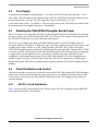
The environment for the reference design is i.MX ADS, together with a daughter board developed around
Focus Enhancements FS453/FS454 processor. Figure 1 shows a high-level block diagram of the daughter
board configuration.
i.MX1
or
i.MXL
ADS
FS453
Daughter
Board
LCDC Connector, I2C, and Clock
Video Connector, RCA, or SCART
Figure 1. TV Output on i.MX ADS Concept Diagram
The design of the daughter board is based on the FS453/FS454 video scan converter processor. For more
information of the processor’s functionality, please refer to FS453/FS454 PC to TV Video Scan Converter
Product Brief and the FS453/FS454 Hardware Reference Manual, that can be obtained by contacting
Focus Enhancements, Inc. (http://www.focusinfo.com)
The i.MX ADS sends an image from the display buffer of its LCDC interface which is connected to the
digital data input of FS453/FS454 daughter board. The received image is converted into an analog format
that can be displayed on a TV monitor.
3
Electrical Characteristics
This section describes the power requirements of the FS453/FS454 daughter board. The FS453/FS454
processor uses two different supply voltages:
•
•
3.1
+3V for I/O supply voltage
+1.8V for the core voltage
I/O Supply
Typically the power for the I/O supply is provided by the i.MX ADS board. The FS453/FS454 daughter
board also allows connection of a +3V supply from an external power source for debug purposes. A jumper
or a zero ohm resistor is used to select the power source used by the FS453/FS454 daughter board.
TV-Out Extension Application Note, Rev. 1
2
Freescale Semiconductor