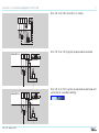
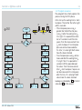
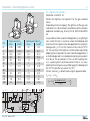
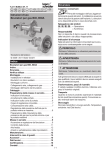
1
Burner control unit BCU 370 Technical Information · GB 6.1.3.2 Edition 11.08 • For modulating, forced draught burners for gas of unlimited capacity in intermittent or continuous operation • Control of fan and butterfly valve • Simple system set-up thanks to optional tightness control and integrated ignition unit • Easy start-up and maintenance thanks to Manual operating mode • Enhanced flexibility and simplified logistics thanks to programmable functions • Easy servicing thanks to informative operating, warning and fault messages • Optionally available with integral field bus interface for simple wiring • EC type-tested and certified, CSA and FM approved www.kromschroeder.com 2 Table of contents Burner control unit BCU 370 . . . . . . . . . . . . . . . . . . . . . . . . . 1 Table of contents . . . . . . . . . . . . . . . . . . . . . . . . . . . . . . . . . . 2 1 Application . . . . . . . . . . . . . . . . . . . . . . . . . . . . . . . . . . . . 4 1.1 Example applications . . . . . . . . . . . . . . . . . . . . . . . . . . . 6 1.1.1 Modulating-controlled forced draught burner . . . . . . . . . . . 6 1.1.2 Modulating-controlled forced draught burner with tightness control . . . . . . . . . . . . . . . . . . . . . . . . . . . . . . . . . . . . . . . 6 1.1.3 Modulating-controlled forced draught burner with pilot burner and tightness control . . . . . . . . . . . . . . . . . . . . . . . . . . . . . 7 1.1.4 Controlling the BCU via PROFIBUS-DP . . . . . . . . . . . . . . . . . . 8 1.1.5 Controlling the BCU and the butterfly valve via PROFIBUS-DP . . . . . . . . . . . . . . . . . . . . . . . . . . . . . . . . . . . . . . . . . 8 2 Certification . . . . . . . . . . . . . . . . . . . . . . . . . . . . . . . . . . . . 9 2.1 PROFIBUS User Organisation . . . . . . . . . . . . . . . . . . . . . 9 3 Function . . . . . . . . . . . . . . . . . . . . . . . . . . . . . . . . . . . . . . 10 3.1 Connection diagrams . . . . . . . . . . . . . . . . . . . . . . . . . . . 10 3.1.1 BCU 370 . . . . . . . . . . . . . . . . . . . . . . . . . . . . . . . . . . . . . . . . 10 3.1.2 BCU 370 with actuator IC 20 . . . . . . . . . . . . . . . . . . . . . . . . 14 3.1.3 Capacity control by adjusting the valve between the Open position and a separate Low position . . . . . . . . . . . . . . . 15 3.1.4 BCU 370..B1 with PROFIBUS-DP . . . . . . . . . . . . . . . . . . . . . 16 3.2 BCU 370 program sequence . . . . . . . . . . . . . . . . . . . . 17 3.2.1 Normal start-up . . . . . . . . . . . . . . . . . . . . . . . . . . . . . . . . . . 17 3.2.2 Quick start, butterfly valve waits in the Ignition position . 19 3.2.3 Quick start, butterfly valve waits in the Closed position . . 21 3.2.4 Start-up without pre-purge, butterfly valve waits in the Closed position . . . . . . . . . . . . . . . . . . . . . . . . . . . . . . . . . . . . . . . 23 3.2.5 Controlled air flow . . . . . . . . . . . . . . . . . . . . . . . . . . . . . . . 25 3.3 Tightness control . . . . . . . . . . . . . . . . . . . . . . . . . . . . . 26 3.3.1 Program sequence . . . . . . . . . . . . . . . . . . . . . . . . . . . . . . . 28 3.4 PROFIBUS-DP . . . . . . . . . . . . . . . . . . . . . . . . . . . . . . . . 29 3.4.1 Configuration, Master-Slave procedure . . . . . . . . . . . . . . . 29 3.4.2 ddressing . . . . . . . . . . . . . . . . . . . . . . . . . . . . . . . . . . . . . . 30 3.4.3 Network technology . . . . . . . . . . . . . . . . . . . . . . . . . . . . . . 30 3.4.4 Configuration . . . . . . . . . . . . . . . . . . . . . . . . . . . . . . . . . . . 31 3.4.5 Bus communication . . . . . . . . . . . . . . . . . . . . . . . . . . . . . . 31 BCU 370 · Edition 11.08 3.5 Program status . . . . . . . . . . . . . . . . . . . . . . . . . . . . . . . 33 3.6 Fault message (blinking) . . . . . . . . . . . . . . . . . . . . . . . 34 3.6.1 Reaction to process faults . . . . . . . . . . . . . . . . . . . . . . . . . . 36 4 Parameters . . . . . . . . . . . . . . . . . . . . . . . . . . . . . . . . . . . 39 4.1 Scanning the parameters . . . . . . . . . . . . . . . . . . . . . . . . 41 4.2 Flame control . . . . . . . . . . . . . . . . . . . . . . . . . . . . . . . . . 41 4.2.1 Burner flame signal . . . . . . . . . . . . . . . . . . . . . . . . . . . . . . . 41 4.2.2 Burner switch-off threshold . . . . . . . . . . . . . . . . . . . . . . . . 41 4.2.3 UVS check (1× in 24 hours) . . . . . . . . . . . . . . . . . . . . . . . . . 41 4.3 Behaviour during start-up . . . . . . . . . . . . . . . . . . . . . . 42 4.3.1 Minimum burner pause time tBP . . . . . . . . . . . . . . . . . . . . 4.3.2 Burner start-up attempts . . . . . . . . . . . . . . . . . . . . . . . . . . 4.3.3 Switch-on delay time tE . . . . . . . . . . . . . . . . . . . . . . . . . . . 4.3.4 Pre-ignition time tVZ . . . . . . . . . . . . . . . . . . . . . . . . . . . . . . 4.3.5 1st safety time on start-up, burner/pilot burner tSA1 . . . . . 4.3.6 1st flame proving period, burner/pilot burner tFS1 . . . . . . 4.3.7 2nd safety time on start-up, main burner tSA2 . . . . . . . . . 4.3.8 2nd flame proving period, main burner tFS2 . . . . . . . . . . . 42 42 43 43 44 44 45 45 4.4 Behaviour during operation . . . . . . . . . . . . . . . . . . . . 46 4.4.1 Minimum combustion time tB . . . . . . . . . . . . . . . . . . . . . . 46 4.4.2 Controller enable signal delay time tRF . . . . . . . . . . . . . . 46 4.4.3 Safety time during operation tSB . . . . . . . . . . . . . . . . . . . . 46 4.4.4 Behaviour in the event of flame failure during operation 47 4.4.5 Last fault signal . . . . . . . . . . . . . . . . . . . . . . . . . . . . . . . . . . 47 4.4.6 V2 during burner operation . . . . . . . . . . . . . . . . . . . . . . . . 48 4.5 Monitoring/tightness control . . . . . . . . . . . . . . . . . . . . 49 4.5.1 Min. gas pressure monitoring . . . . . . . . . . . . . . . . . . . . . . 49 4.5.2 Digital input function . . . . . . . . . . . . . . . . . . . . . . . . . . . . . . 49 4.5.3 Air monitoring during pre-purge . . . . . . . . . . . . . . . . . . . . 49 4.5.4 Air monitoring during operation . . . . . . . . . . . . . . . . . . . . 50 4.5.5 Tightness test period tP . . . . . . . . . . . . . . . . . . . . . . . . . . . 51 4.5.6 Calculation example . . . . . . . . . . . . . . . . . . . . . . . . . . . . . . 52 4.6 Air control . . . . . . . . . . . . . . . . . . . . . . . . . . . . . . . . . . . 53 4.6.1 Valve control . . . . . . . . . . . . . . . . . . . . . . . . . . . . . . . . . . . . 4.6.2 Pre-purge . . . . . . . . . . . . . . . . . . . . . . . . . . . . . . . . . . . . . . 4.6.3 Quick start starts in ... . . . . . . . . . . . . . . . . . . . . . . . . . . . . . 4.6.4 Pre-purge time tPV . . . . . . . . . . . . . . . . . . . . . . . . . . . . . . . t = To be continued 53 53 54 55 Table of contents 4.6.5 Post-purge time tPN . . . . . . . . . . . . . . . . . . . . . . . . . . . . . . 56 4.6.6 Fan run up time tGV . . . . . . . . . . . . . . . . . . . . . . . . . . . . . . 57 4.7 Control using PROFIBUS-DP . . . . . . . . . . . . . . . . . . . . . 58 4.7.1 Bus control activation . . . . . . . . . . . . . . . . . . . . . . . . . . . . . 58 4.7.2 Bus control limitation . . . . . . . . . . . . . . . . . . . . . . . . . . . . . 58 4.8 Manual mode . . . . . . . . . . . . . . . . . . . . . . . . . . . . . . . . 60 4.8.1 Operating time in manual mode . . . . . . . . . . . . . . . . . . . . 60 4.9 Fault messages . . . . . . . . . . . . . . . . . . . . . . . . . . . . . . . 61 4.9.1 The last 10 fault messages . . . . . . . . . . . . . . . . . . . . . . . . . 61 4.10 Password . . . . . . . . . . . . . . . . . . . . . . . . . . . . . . . . . . . 61 4.10.1 User-defined password . . . . . . . . . . . . . . . . . . . . . . . . . . . 61 5 Selection . . . . . . . . . . . . . . . . . . . . . . . . . . . . . . . . . . . . . 62 5.1 Type code . . . . . . . . . . . . . . . . . . . . . . . . . . . . . . . . . . . 62 6 Project planning information . . . . . . . . . . . . . . . . . . . . . 63 6.1 Cable selection . . . . . . . . . . . . . . . . . . . . . . . . . . . . . . . 63 6.1.1 Ionisation cable . . . . . . . . . . . . . . . . . . . . . . . . . . . . . . . . . . 63 6.1.2 UV cable . . . . . . . . . . . . . . . . . . . . . . . . . . . . . . . . . . . . . . . . 63 6.1.3 Ignition cable . . . . . . . . . . . . . . . . . . . . . . . . . . . . . . . . . . . . 63 6.2 Fan control . . . . . . . . . . . . . . . . . . . . . . . . . . . . . . . . . . 63 6.3 Controlling the butterfly valve . . . . . . . . . . . . . . . . . . . 64 6.4 Safety interlock (Limits) . . . . . . . . . . . . . . . . . . . . . . . . . 64 6.5 Too many remote resets . . . . . . . . . . . . . . . . . . . . . . . 64 6.6 Protecting the ignition unit from overload . . . . . . . . . 64 6.7 Wiring . . . . . . . . . . . . . . . . . . . . . . . . . . . . . . . . . . . . . . 64 3 8 Accessories . . . . . . . . . . . . . . . . . . . . . . . . . . . . . . . . . . . 67 8.1 High-voltage cable . . . . . . . . . . . . . . . . . . . . . . . . . . . . . 67 8.2 BCSoft . . . . . . . . . . . . . . . . . . . . . . . . . . . . . . . . . . . . . . . 67 8.3 Radio interference suppressed electrode adapters . . 67 8.4 Connection kit BCU 370 . . . . . . . . . . . . . . . . . . . . . . . . . 67 8.5 Set of stickers BCU 370 . . . . . . . . . . . . . . . . . . . . . . . . . 67 8.6 Device master data file for BCU 370..B1 . . . . . . . . . . . . 67 9 Technical data . . . . . . . . . . . . . . . . . . . . . . . . . . . . . . . . 68 9.1 PROFIBUS-DP . . . . . . . . . . . . . . . . . . . . . . . . . . . . . . . . . 69 9.2 Operating controls and dimensions . . . . . . . . . . . . . . 70 10 Legend . . . . . . . . . . . . . . . . . . . . . . . . . . . . . . . . . . . . . . 71 11 Glossary . . . . . . . . . . . . . . . . . . . . . . . . . . . . . . . . . . . . . . 72 11.1 Safety shut-down . . . . . . . . . . . . . . . . . . . . . . . . . . . . . 72 11.2 Fault lock-out . . . . . . . . . . . . . . . . . . . . . . . . . . . . . . . . 72 11.3 Warning signal . . . . . . . . . . . . . . . . . . . . . . . . . . . . . . 72 11.4 Timeout 25 s/250 s . . . . . . . . . . . . . . . . . . . . . . . . . . . 72 12 Annex . . . . . . . . . . . . . . . . . . . . . . . . . . . . . . . . . . . . . . . 73 12.1 Status and fault messages for PROFIBUS-DP . . . . . . 73 Feedback . . . . . . . . . . . . . . . . . . . . . . . . . . . . . . . . . . . . . . . 76 Contact . . . . . . . . . . . . . . . . . . . . . . . . . . . . . . . . . . . . . . . . 76 6.7.1 Single-electrode operation with external ignition unit . . . 65 6.8 BCU switched off . . . . . . . . . . . . . . . . . . . . . . . . . . . . . 65 6.9 Note on EC or CSA and FM type-examination . . . . . . 65 6.10 Contact protection devices . . . . . . . . . . . . . . . . . . . . . 65 6.11 Installation . . . . . . . . . . . . . . . . . . . . . . . . . . . . . . . . . . 65 6.12 Protective circuits . . . . . . . . . . . . . . . . . . . . . . . . . . . . 65 7 Flame control ... . . . . . . . . . . . . . . . . . . . . . . . . . . . . . . . 66 7.1 ... with ionisation sensor . . . . . . . . . . . . . . . . . . . . . . . . 66 7.2 ... with UV sensor . . . . . . . . . . . . . . . . . . . . . . . . . . . . . 66 BCU 370 · Edition 11.08 t = To be continued 4 BCU 370 Lower section 1 Application The BCU 370 burner control unit controls, ignites and monitors industrial forced draught burners of unlimited capacity in intermittent or continuous operation. It can be used for directly ignited forced draught burners or forced draught burners ignited with pilot burner. The BCU 370 activates the fan and sets the connected butterfly valve to Prepurge and Ignition position. After pre-purge and burner start, the Enable signal is issued to an external controller which positions the butterfly valve in accordance with the output demand. Post-purge occurs after the end of burner operation. The burner control unit BCU 370 monitors the gas and air pressure. An optionally integrated tightness control function checks the valves with an external gas pressure switch. Programmability by means of the optical interface and BCSoft PC software guarantees optimum adaptation to the relevant application. Adjustable start-up attempts and automatic reBCU 370 · Edition 11.08 Upper section start which can be activated ensure the high flexibility of the burner equipment. The quick-start option allows standard-compliant start-up of the forced draught burner without pre-purge after normal shut-down. This avoids unnecessary admission of air into the combustion chamber. The heat output is available as quickly as possible after a temperature demand. t Application The program status, the unit parameters and the level of the flame signal can be read directly from the BCU. An integrated Manual mode allows manual start of the burner and setting of the butterfly valve position independently of the central control system. The BCSoft operator-control and setting software provides a powerful tool for start-up and servicing. To reduce the installation and wiring costs Kromschröder offers an optional Profibus-DP interface to transfer the activation signals and feedbacks. BCU 370 · Edition 11.08 5 Application 6 1.1 Example applications L1 21 BCU 370..I1 25 28 26 24 3 7 DG DL V1 4 VG 5 29 30 31 V2 VG..L 21 18 17 13 GIK IC 20 B VA DL 32 S DG min 9 UV 22 L1 20 19 0 � 90° 90° � 0 23 M BCU 370..I1..D3 25 28 26 24 9 DG 3 7 DL V1 11 DG 5 29 30 31 V2 DG pe/2 VG..L VG DL BCU 370 · Edition 11.08 4 32 GIK IC 20 B VA M 18 17 13 UV S DG min 20 19 0 � 90° 90° � 0 23 22 1.1.1 Modulating-controlled forced draught burner The BCU 370 controls the fan and moves the butterfly valve to pre-purge and ignition position. It issues the Enable signal to the control system after start-up of the burner. 1.1.2 Modulating-controlledforceddraught burner with tightness control In addition to controlling the forced draught burner, the burner control unit also monitors the fail-safe function of the two solenoid valves for gas via the gas pressure switch DG which is set to pe/2. Parameter 27 = 1: V2 is “ON” during burner operation. Application > Example applications L1 21 7 BCU 370..D3 24 DG min 20 19 0 � 90° 90° � 0 23 22 9 DG 37 DL 45 V1 V2 11 6 29 30 31 DG V3 DG pe/2 VG DL 32 13 18 17 GIK IC 20 B VA UV S VG..L VG BCU 370 · Edition 11.08 1.1.3 Modulating-controlledforceddraught burner with pilot burner and tightness control A pilot burner ignites the main burner and is switched off during the main burner’s safety time. Parameter 27 = 0: V2 is “OFF”, i.e. interrupted pilot burner, during burner operation. 25 28 26 M Application > Example applications 8 1.1.4 Controlling the BCU via PROFIBUS-DP The BCU 370..B1 issues the Enable signal to the temperature controller for capacity control. The temperature controller then controls the butterfly valve directly. L1, BUS PLC Profibus-DP BCU 370..B1 25 ϑ 3PS L1, 0 � 90° 90° � 0 28 26 29 30 31 32 ϑ Temperature controller M Temperature controller PLC BUS L1, Profibus-DP BCU 370..B1-3 ϑ 3PS 0 � 90° 90° � 0 ϑ L1, 29 30 31 M BCU 370 · Edition 11.08 32 1.1.5 Controlling the BCU and the butterfly valve via PROFIBUS-DP The BCU 370..B1-3 receives positioning information for the butterfly valve from the temperature controller via the PROFIBUS-DP and activates the butterfly valve following controller enable. 9 2 Certification EC type-tested and certified pursuant to – Gas Appliances Directive (90/396/EEC) in conjunction with EN 298, – Low Voltage Directive (73/23/EEC) in conjunction with the relevant standards, – Electromagnetic compatibility 89/336/EEC in conjunction with the relevant standards relating to radiation. AGA Approval No. 6478 in preparation CSA and FM approved Canadian Standards Association Class: 3335-01 and 3335-81 Systems (Gas-)Automatic Ignition and Components Factory Mutual Research Class: 7611 Combustion Safeguards and Flame Sensing System Suitable for applications pursuant to NFPA 85 and NFPA 86 2.1 PROFIBUS User Organisation BCU 370..B1 PUO = PROFIBUS User Organisation Complies with the requirements of EN 50170-2 BCU 370 · Edition 11.08 10 C S1 S L A Z M V2 V3 R C F1 F3 s1 r v1 v2 v3 230V~ l 90° � 0 V1 0 � 90° BCU 370..I1 c r1 c 1 2 3 4 5 6 7 8 9 10 11 12 13 14 15 16 PE N s 17 18 19 20 21 22 23 24 25 26 27 28 29 30 31 32 max. 1 A, max. 1 A, 253 V 253 V V1 V2 V3 p p p DL DG min DG max I Z M 3PS ϑ L1 (L1) N (L2) PE 3 Function 3.1 Connection diagrams 3.1.1 BCU 370 The drawing shows the BCU 370..I1 with integrated ignition unit, ionisation control and double-electrode operation. For cable selection and wiring, see Project planning information. For the explanation of symbols, see Legend. t BCU 370 · Edition 11.08 Function > Connection diagrams > BCU 370 11 BCU 370..I1 for 120 V and 230 V, UV control 13 14 15 16 PE 3 2 UVS 1 BCU 370..I2 13 14 15 16 3 2 UVS 1 BCU 370..I3 PE Z 13 14 15 16 N BCU 370..I2 for 230 V, ignition by electrode to electrode Z PE N BCU 370..I3 for 120 V, ignition by electrode to electrode with centre tap for secondary earthing t 3 2 UVS 1 BCU 370 · Edition 11.08 Z Z Function > Connection diagrams > BCU 370 12 BCU 370 with external ignition transformer, e.g. TZI or TGI. BCU 370 13 14 15 16 I BCU 370 PE N Z 13 14 15 16 PE N BCU 370 with single-electrode operation, which requires an external ignition transformer TZI or TGI. BCU 370..D3, gas pressure switch DG for tightness control BCU 370..D3 t 11 12 p pe DG BCU 370 · Edition 11.08 2 Function > Connection diagrams > BCU 370 BCU 370..U1 24 V 0V 1 2 13 14 15 16 UVD 1 3 4 5 6 PE 13 24 V 1 2 0V 3 4 5 6 – + 0–20 mA BCU 370 · Edition 11.08 13 UVD 1 BCU 370..U1 with UV sensor UVD 1 for continuous operation Connection of the 24 V DC power supply with separate wiring in the lower section of the BCU. The 0 – 20 mA current output is not required for normal operation. If it is used for the display in a control room for example, then the cable must be connected in the lower section of the BCU, so that the 0 – 20 mA signal can be routed via a screened cable. Length of the unscreened cable from the UV sensor to the BCU: max. 5 m. Function > Connection diagrams 14 3.1.2 BCU 370 with actuator IC 20 The “closed contact” (90° ➔ 0) of the external three-point step controller (3PS) can be connected to terminal 26 or 27. Terminal 26: The controller operates between the Open and Ignition positions. Terminal 27: The controller operates between the Open and Closed positions. 90° � 0 0 � 90° BCU 370 r 25 26 27 28 29 30 31 32 3PS 16 15 13 12 11 8 7 6 90° � 0 0 � 90° 90° 0 L1 (L1) N (L2) PE 4 3 2 1 IC 20 PE S11 S2 S10 S1 S3 S4 M BCU 370 · Edition 11.08 90° � 0 0 � 90° Function > Connection diagrams r 25 26 27 28 29 30 31 32 – 3PS BCU 370 · Edition 11.08 M Min + 15 3.1.3 Capacity control by adjusting the valve between the Open position and a separate Low position This connection is used if the valve position to be approached is below the Ignition position. Standard wiring of BCU 370 and BCU 370..B1 without threepoint step control function Valve position Upper end position Open Lower end position Closed Lower end position Low Lower end position Ignition Activation of terminal 28 27 Via separate limit switch 26 Function > Connection diagrams C S1 S L A Z M V2 V3 R C F1 F3 s1 r v1 v2 v3 230V~ l 90° � 0 V1 0 � 90° BCU 370..I1..B1 16 c c 1 2 3 4 5 6 7 8 9 10 11 12 13 14 15 16 V1 V2 V3 p p p DL DG min DG max I PE N 24 25 26 27 28 29 30 31 32 Z M 3PS L1 (L1) N (L2) PE BCU 370..B1 ON OFF 2B 2A 1B 1A PROFIBUS-DP 3.1.4 BCU 370..B1 with PROFIBUS-DP Function see “PROFIBUS-DP” For cable selection and wiring, see Project planning information. BCU 370 · Edition 11.08 For the explanation of symbols, see Legend. Function 17 Switch on BCU 370 In the event of fault signal: Reset 00 Start-up position/standby H0 Start-up with ϑ signal H0 Switch-on delay time tE running (P22) 01 Fan run up time tGV (P20) A1 Butterfly valve moves to Open position P1 Pre-purge time tPV running (P18) A2 Butterfly valve moves to Ignition position 03 Pre-ignition time tVZ running (P21) Ignition activated 04 Safety time tSA1 running for burner/pilot burner (P12), V1 and V2 open 05 BCU 370 · Edition 11.08 Flame proving period tFS1 running for burner/pilot burner (P13) 3.2 BCU 370 program sequence 3.2.1 Normal start-up If a fault from the preceding operating cycle is still being signalled after switching on, it will be necessary to reset this first. Once the start-up signal (ϑ) has been applied, the switch-on delay tE starts to elapse. During the fan run up time tGV which follows, the fan starts with the butterfly valve being closed. The butterfly valve then moves from the Closed to the Open position. After pre-purge, it moves back to the Ignition position. The running times depend on the respective actuator. The BCU waits for actuator feedback before continuing the program sequence. Now the BCU activates pre-ignition tVZ and then opens valves V1 and V2 for the pilot burner. The ignition time tZ is constant. After the flame proving period for the pilot burner tFS1, valve V3 opens to ignite the main burner. t running for burner/pilot burner (P13) Function > BCU 370 program sequence > Normal start-up 06 Safety time tSA2 running for main burner (P14), V3 opens If parameter P27 = 0: V2 is switched off 07 Flame proving period tFS2 running for main burner (P15) H8 Controller enabler signal delay time tRF (P29) 08 Controller enable signal 08 Normal shut-down via ϑ signal P9 Post-purge time tPN running (P19) A0 Butterfly valve moves to Closed position 00 Start-up position/standby BCU 370 · Edition 11.08 18 If parameter 27 = 0, V2 closes at the end of the main burner safety time tSA2. The pilot burner is switched off. Then the flame proving period for the main burner tFS2 and the controller enable signal delay time tRF start to elapse. Afterwards, the BCU issues the Enable signal to the controller. If there is no pilot burner, program steps 06 and 07 will be omitted. As soon as the start-up signal (ϑ) is switched off, post-purge starts. The butterfly valve moves to the Ignition position during this time, then to the Closed position. Next the BCU rests in the start-up position/standby. Function > BCU 370 program sequence 00 Start-up position/standby H0 Start-up with ϑ signal H0 Switch-on delay time tE running (P22) 01 Fan run up time tGV (P20) 02 Waiting time tW 03 Pre-ignition time tVZ running (P21) Ignition activated 04 Safety time tSA1 running for burner/pilot burner (P12), V1 and V2 open 05 Flame proving period tFS1 running for burner/pilot burner (P13) 06 Safety time tSA2 running for main burner (P14), V3 opens If parameter P27 = 0: V2 is switched off BCU 370 · Edition 11.08 07 19 3.2.2 Quick start, butterfly valve waits in the Ignition position Parameter 06 = 0, parameter 28 = 0 Quick start is the same as normal start, except that pre-purge is dispensed with. The burner starts quicker. This results in improved control quality, since there is no dead time, the energy is used better and no cold air is fed to the combustion chamber. The BCU 370 only carries out a quick start if the last shut-down was a normal shutdown. No more than 24 hours may have elapsed and the BCU must have been switched on. In contrast to the “normal start-up”, in the case of a quick start, program steps A1 , P1 and A2 .will be omitted. If there is no pilot burner, program steps 06 und 07 will also be omitted. t If parameter P27 = 0: V2 is switched off Function > BCU 370 program sequence > Quick start, butterfly valve waits in the Ignition position 07 Flame proving period tFS2 running for main burner (P15) H8 Controller enabler signal delay time tRF (P29) 08 Controller enable signal 08 Normal shut-down via ϑ signal P9 Post-purge time tPN running (P19) A1 Butterfly valve moves to Open position A2 Butterfly valve moves to Ignition position 00 Start-up position/standby BCU 370 · Edition 11.08 20 After normal shut-down, the post-purge time tPN starts to elapse and then the butterfly valve moves to the Ignition position in preparation for the next start. NOTE: Quick Start is not allowed for units with FM or CSA approval. Function > BCU 370 program sequence 00 Start-up position/standby H0 Start-up with ϑ signal H0 Switch-on delay time tE running (P22) A1 Butterfly valve moves to Open position A2 Butterfly valve moves to Ignition position 01 Fan run up time tGV (P20) 02 Waiting time tW 03 Pre-ignition time tVZ running (P21) Ignition activated 04 Safety time tSA1 running for burner/pilot burner (P12), V1 and V2 open 05 Flame proving period tFS1 running for burner/pilot burner (P13) BCU 370 · Edition 11.08 06 21 3.2.3 Quick start, butterfly valve waits in the Closed position Parameter 06 = 0, parameter 28 = 1 Pre-purge will also be omitted for this type of quick start. To prevent cold air from entering the combustion chamber while the BCU is in start-up position/ standby, the butterfly valve waits in the Closed position. The BCU 370 only carries out a quick start if the last shut-down was a normal shutdown. No more than 24 hours may have elapsed and the BCU must have been switched on. After the switch-on delay time tE, the butterfly valve moves to the Ignition position. The Ignition position is always approached from the top. Therefore, the butterfly valve moves to the Open position first. t running for burner/pilot burner (P13) Function > BCU 370 program sequence > Quick start, butterfly valve waits in the Closed position 22 If there is no pilot burner, program steps 06 and 07 will be omitted. 06 Safety time tSA2 running for main burner (P14), V3 opens If parameter P27 = 0: V2 is switched off 07 Flame proving period tFS2 running for main burner (P15) H8 Controller enabler signal delay time tRF (P29) 08 Controller enable signal 08 Normal shut-down via ϑ signal P9 Post-purge time tPN running (P19) A0 Butterfly valve moves to Closed position 00 Start-up position/standby BCU 370 · Edition 11.08 As soon as the start-up signal (ϑ) is switched off, post-purge starts. The butterfly valve moves to the Ignition position during this time, then to the Closed position. Next the BCU rests in the start-up position/standby. NOTE: Quick Start is not allowed for units with FM or CSA approval. Function > BCU 370 program sequence Switch on BCU 370 In the event of fault signal: Reset 00 Start-up position/standby H0 Start-up with ϑ signal H0 Switch-on delay time tE running (P22) A1 Butterfly valve moves to Open position A2 Butterfly valve moves to Ignition position 01 Fan run up time tGV (P20) 02 Waiting time tW 03 Pre-ignition time tVZ running (P21d 04 Safety time tSA1 running for burner/pilot burner (P12), V1 and V2 open 05 Flame proving period tFS1 running for burner/pilot burner (P13) BCU 370 · Edition 11.08 23 3.2.4 Start-up without pre-purge, butterfly valve waits in the Closed position Parameter 18 = 0, parameter 28 = 1 If a fault from the preceding operating cycle is still being signalled after switching on, it will be necessary to reset this first. Once the start-up signal (ϑ) has been applied, the switch-on delay tE starts to elapse. Afterwards, the butterfly valve moves from the Closed to the Open position and then to the Ignition position. During the fan run up time tGV which follows, the fan starts with the butterfly valve being set to Ignition position. After the waiting time tW, the BCU activates pre-ignition tVZ and then opens valves V1 and V2 for the pilot burner. The ignition time tZ is constant. After the flame proving period for the pilot burner tFS1, valve V3 opens to ignite the main burner. t running for burner/pilot burner (P13) Function > BCU 370 program sequence > Start-up without pre-purge, butterfly valve waits in the Closed position 06 Safety time tSA2 running for main burner (P14), V3 opens If parameter P27 = 0: V2 is switched off 07 Flame proving period tFS2 running for main burner (P15) H8 Controller enabler signal delay time tRF (P29) 08 Controller enable signal 08 Normal shut-down via ϑ signal P9 Post-purge time tPN running (P19) A0 Butterfly valve moves to Closed position 00 Start-up position/standby BCU 370 · Edition 11.08 24 If parameter 27 = 0, V2 closes at the end of the main burner safety time tSA2. The pilot burner is switched off. Then the flame proving period for the main burner tFS2 and the controller enable signal delay time tRF start to elapse. Afterwards, the BCU issues the Enable signal to the controller. If there is no pilot burner, program steps 06 and 07 will be omitted. As soon as the start-up signal (ϑ) is switched off, post-purge starts. The butterfly valve moves to the Ignition position during this time, then to the Closed position. Next the BCU rests in the start-up position/standby. NOTE: Quick Start is not allowed for units with FM or CSA approval. Function 90° � 0 0 � 90° 25 r r1 N s 17 18 19 20 21 22 23 24 25 26 27 28 29 30 31 32 max. 1 A, max. 1 A, 253 V 253 V M 3PS ϑ L1 (L1) N (L2) PE BCU 370 · Edition 11.08 3.2.5 Controlled air flow The controlled air flow function is enabled when the controlled air flow input, terminal 22 or via PROFIBUS, is activated. Cold air is fed to the combustion chamber, e.g. for cooling. Following the air pressure switch DL rest position check, the BCU 370 starts the fan and opens the butterfly valve to the Open position. The pressure switch for air DL monitors the air pressure. If the start-up signal (J) is applied during controlled air flow, the burner is started. If the elapsed controlled air flow time is at least as long as the set pre-purge time, the burner starts immediately after the Ignition position has been approached. If it is shorter, the total air volume is supplied until the end of the pre-purge time. Activation of the controlled air flow input is not required for normal burner start. Activation of the controlled air flow function during burner operation will be ignored. Function 26 3.3 Tightness control L1 21 BCU 370..I1..D3 25 28 26 24 DG min 9 DG 3 7 DL V1 11 DG 5 29 30 31 V2 DG pe/2 VG..L VG DL BCU 370 · Edition 11.08 4 32 GIK IC 20 B VA M 18 17 13 UV S 22 20 19 0 � 90° 90° � 0 23 On BCU 370..D3, the tightness control monitors the fail-safe function of the gas solenoid valves if parameter 24 is set to 3. The aim of the tightness control is to identify an inadmissible leak on one of the gas solenoid valves and to prevent burner start. The other gas solenoid valve continues working properly and takes over the safe shut-off of the gas supply. The test takes place during pre-purge. The fan runs and the air pressure opens the air/gas ratio control GIK. In the case of quick start (parameter 06 = 0), the test takes place after burner operation during post-purge. The pre- and post-purge times (parameters 18 and 19) must be set so that their duration is at least as long as the test period tP. Function > Tightness control L1 21 27 BCU 370..D3 25 28 26 24 DG min 20 19 0 � 90° 90° � 0 23 22 9 DG 37 DL 45 V1 V2 11 6 29 30 31 DG V3 DG pe/2 VG DL 32 13 18 17 GIK IC 20 B VA UV S VG..L VG BCU 370 · Edition 11.08 Downstream of the gas solenoid valve V2 on the burner side, the pipe to the burner must be open so that the space between valves V1 and V2 can be vented. The pressure switch DG monitors the pressure between the two valves. It must be set to half of the inlet pressure pe/2 in order to check both valves with equal sensitivity. In pilot/main burner systems with three gas solenoid valves, V2 and V3 are checked simultaneously. M Function > Tightness control 28 V1 TEST START pe tW + V2 V2 p pZ > e 2 pz – V1 OK V2 0 � Ι V1 0 � Ι tL = 3 s tL = 3 s V2 Ι � 0 V1 Ι � 0 tM tM p pZ > e 2 + – p pZ > e 2 + – V1 OK OK BCU 370 · Edition 11.08 V1 V2 V2 OK 3.3.1 Program sequence The program flow chart explains the process during the TEST phase. After start-up the waiting time tW starts to elapse. Then either the left or right path is executed. – If the interspace pressure pZ is greater than half of the inlet pressure pe/2 after the waiting time tW, V2 is tight. V2 is opened for a duration of 3 seconds to vent the interspace. Then the measurement time tM starts to elapse. If no interspace pressure can be measured after this time, V1 is also tight. Both valves have thus been checked. – If no interspace pressure pZ can be measured after the waiting time tW, V1 is tight. Then V1 is opened for 3 seconds to fill the space between the valves. Then the measurement time tM starts to elapse. If a pressure can be measured in the interspace after this time, V2 is also tight. Both valves have thus been checked. Leakage is indicated by 36 for the first valve and 37 for the second. Function 29 3.4 PROFIBUS-DP PROFIBUS is a manufacturer-independent, open field bus standard for diverse applications. PROFIBUS-DP is a bus variant for communication between automation systems and distributed peripherals at the field level, optimised for speed and low connection costs. On PROFIBUS-DP, the individual bus stations are connected via a 2-core shielded cable as standard. 3.4.1 Configuration, Master-Slave procedure PROFIBUS-DP is structured as a Master-Slave system. This allows mono-master or multi-master systems to be implemented. A distinction is made between three device types: – DP Master Class 1 (DPM1) DPM1 devices are central controllers which exchange data with the distributed stations (slaves) on the basis of a defined cycle. This includes, for instance, the PLC, PC, CNC or VME systems with which the PROFIBUS-DP is operated. – DP Master Class 2 (DPM2) DPM2 devices are programming, project planning or operator-control devices. They are used for configuration and commissioning of the system or for system operation and visualisation in ongoing operation. – DP Slaves The devices which transmit input information from the periphery to the master and which issue output information from the master to the periphery are referred to as “slaves”. This also includes the BCU..B1. BCU 370 · Edition 11.08 Function > PROFIBUS-DP The use of a standard bus system offers massive benefits compared to manufacturer-specific bespoke solutions. Time-tested hardware components, standardised connection methods and a series of tools of bus diagnostics and optimisation are available on the market from a whole range of manufacturers. The widespread use of the system ensures that the planning and service personnel are very familiar with how the system operates and how to handle it and can therefore operate the system efficiently. 30 3.4.3 Network technology All devices are connected in a bus structure (line). Up to 32 stations (masters or slaves) can be connected in a single segment. The beginning and end of each segment is fitted with an active bus terminator. Both bus terminators must have a permanent power supply to ensure error-free operation. The bus terminator can be switched in the lower section of the unit. 3.4.2 ddressing A maximum of 126 units (masters and slaves) can be connected to a PROFIBUS-DP system. Each station is assigned an individual PROFIBUS address which can be set between 0 and 126 using two code switches on the BCU..B1 board. If more than 32 stations are implemented or if there is a need to expand the network area, repeaters (amplifiers) must be used to link the individual bus segments. The left switch sets the tens or hundreds for the address, whilst the right switch sets the units. BCU 370 · Edition 11.08 Function > PROFIBUS-DP 31 BCU 370 · Edition 11.08 0 – 25.5 μA of the burner 255 steps Status and fault messages (see Table) Reserved 3.4.4 Configuration Output bytes (master -> BCU) When planning a PROFIBUS-DP system, unit-specific paramBit Byte 0 eters of each station are to be taken into account. 0 Reset To allow for simple and standardised planning, the parameters 1 Start-up of the BCU..B1 have been summarised in a so-called device 2 Controlled air flow master data file (DMD). The file structure is standardised so 3 that it can be read by the planning units of different manu4 facturers. 5 The DMD file can be downloaded from www.docuthek.com, 6 Open* once you have registered, or is available on diskette (see Ac7 Close* cessories). The steps required to copy the file are described * Only on BCU 370..B1-3, three-point step control via PROFIBUSin the instructions for the automation system. DP 3.4.5 Bus communication t Input bytes (BCU -> master) Bit Byte 0 Byte 1 Byte 2 Byte 3 0 Burner operation 1 2 Fault lock-out 3 Controlled air flow Open position 4 reached* Closed position 5 reached* 6 ON 7 Manual mode Function > PROFIBUS-DP > Bus communication I/O bytes: The programmer can choose the data to be transferred. BCU 370, basic I/O BCU 370, standard I/O Inputs 1 byte 4 byte Outputs 1 byte 1 byte Baud rate: Up to 1500 kbit/s. The max. range per segment depends on the baud rate: Baud rate [kbit/s] Range [m] 93.75 1200 187.5 1000 500 400 1500 200 The specified ranges may be increased by using repeaters. No more than three repeaters should be connected in series. The specified ranges relate to bus cable type A (two-core, shielded and twisted), e.g. Siemens, Order No.: 6XV1830-0EH10 or Lapp cable unitronic, Order No.: 2170-220T. BCU 370 · Edition 11.08 32 Function 33 3.5 Program status DISPLAY 00 Program status Start-up position/standby A0 Butterfly valve moves to Closed position 0 01 Air monitor rest position check A1 Butterfly valve moves to Open position 1 P1 Air monitor operating position check A2 Butterfly valve moves to Ignition position 02 Waiting time tW 03 Pre-ignition time tVZ 04 1st safety time on start-up tSA1 05 1st flame proving period tFS1 06 2nd safety time on start-up tSA2 07 2nd flame proving period tFS2 H8 Controller enable signal delay time 08 Operation/Controller enable H0 Waits for switch-on delay or min. pause time C1 Controlled air flow P9 Post-purge time tPN Fan run up time tGV Pre-purge time tPV In manual mode, two dots blink on the display. BCU 370 · Edition 11.08 Function 34 3.6 Fault message (blinking) Flame simulation 01 Fault lockout Start-up without flame signal 04 Fault message (blinking) flame proving period 05 Flame failure during 2nd safety time 06 Flame failure during 2nd flame proving period 07 Flame failure during operation 08 Too many remote resets 10 Flame failure during 1st Safety interlock failure 50 Permanent remote reset 52 Timing cycle too short 53 DGmin. oscillating 55 Bus module error E Bus fault Open + Close set simultaneously P 56 Fault Valve feedback 35 Tightness control: V1 leaking BCU 370 · Edition 11.08 Safety shut-down Warning signal 36 Tightness control: V2/V3 leaking 37 Fault Air monitor break contact check 0 Fault Air monitor make contact check 1 Fault Air supply during pre-purge P Fault Air supply in program step X X X Fault DGmax. in program step X t DISPLAY Function > Fault message (blinking) 35 Fault message (blinking) Fault DGmin. in program step X DISPLAY Fault lockout Safety shut-down Warning signal Safety shut-down Warning signal X Butterfly valve closed position not reached A0 Fault lockout Butterfly valve open position not reached A1 Butterfly valve ignition position not reached A2 Fault message (blinking) BCU 370 · Edition 11.08 DISPLAY Function > Fault message (blinking) 36 3.6.1 Reaction to process faults The BCU 370 reacts differently to process faults in different program steps. If, for example, the signal from air pressure switch DL drops during pre-purge, 1 flashes on the display and a timeout time of 25 seconds starts to elapse. If the signal is not applied again, the BCU carries out three further start-up attempts. t BCU 370 · Edition 11.08 All All except tSA1 + tSA2 tSA1 tSA2 Rest position check Operating position check Pre-purge time Valve moves to Ignition position Waiting time Pre-ignition time tSA1 tFS1 tSA2 tFS2 Controller enable waiting time Start-up attempts1) Safety shut-down Immediate fault lock-out Fault message XX XX 04 06 0 1 P1 A2 02 03 04 05 06 07 H8 Restart2) DGmax. (11) drops DGmin. (9) drops not pending after tSA1 not pending after tSA2 DL (7) pending not pending drops drops drops drops drops drops drops drops drops During program step Timeout 25 s Signal Signal status (terminal) BCU 370’s reaction Normal shut-down Process fault 4) 4) 4) X X 4 6 0 1 P 2 2 3 4 5 6 7 8 Function > Fault message (blinking) > Reaction to process faults 37 DL (7) drops drops drops ϑ (21) drops drops Safety interdrops lock (24) Flame (13) pending pending pending pending pending not pending after tSA1 drops drops drops drops drops t BCU 370 · Edition 11.08 08 C1 XX 04 06 Operation Controlled air flow All except tSA1 + tSA2 tSA1 tSA2 Rest position check Operating position check Pre-purge time Valve moves to Ignition position Waiting time tSA1 tFS1 tSA2 tFS2 Controller enable waiting time Operation Fault message Restart2) Start-up attempts1) 8 P 3) 3) XX All 0 1 P1 A2 02 04 05 06 07 H8 08 Safety shut-down Immediate fault lock-out During program step Timeout 25 s Signal Signal status (terminal) BCU 370’s reaction Normal shut-down Process fault 6) 50 01 01 01 01 01 04 05 06 07 08 08 Function > Fault message (blinking) > Reaction to process faults 1} According to parameter 07. If the last start-up attempt fails, a fault lock-out occurs. 2} According to parameter 08. If the restart fails, a fault lock-out occurs. 3} Safety time elapses completely. 4} BCU restarts as soon as the signal is applied again. 5) The program sequence is blocked. 6) 4) and 5) BCU 370 · Edition 11.08 38 39 4 Parameters Description Parameter Burner flame signal Burner switch-off threshold Last fault signal Air monitoring during pre-purge Air monitoring during operation 01 02 03 04 05 Pre-purge 06 Burner start-up attempts 07 Behaviour in the event of flame failure during operation 08 Safety time during operation tSB Minimum combustion time tB Minimum burner pause time tBP 1st safety time on start-up, burner/pilot burner tSA1 1st flame proving period, burner/pilot burner tFS1 2nd safety time on start-up, main burner tSA2 2nd flame proving period, main burner tFS2 09 10 11 12 13 14 15 Operating time in manual mode 16 UVS check (1 x in 24 hours) Pre-purge time tPV Post-purge time tPN Fan run up time tGV 17 18 19 20 t BCU 370 · Edition 11.08 Value range 0 – 25 µA 1 – 20 µA XX 0 = Off; 1 = On 0 = Off; 1 = On 0 = Quick start; 1 = On each start-up 1 – 4 0 = Fault lock-out; 1 = Restart 1; 2 s 0 – 250 s 0 – 250 s 2; 3; 5; 10 s 0; 2; 5; 10; 20 s 0; 2; 3; 5; 10 s 0; 2; 5; 10; 20 s 0 = Unlimited; 1 = Limited to 5 minutes 0 = Off; 1 = On 0 – 250 s 0 – 250 s 0 – 25 s Default Adjustable1) 1 µA v 1 1 1 1 0 1s 0s 0s 5s 2s 3s 2s 1 0 30 s 0s 2s Parameters Description 40 Parameter Pre-ignition time tVZ Switch-on delay time tE Min. gas pressure monitoring Digital input function 21 22 23 24 Valve control Tightness test period tP 25 26 V2 during burner operation Quick start starts in 27 28 Controller enable signal delay time tRF 29 User-defined password Bus control activation (on BCU..B1-3) Bus control limitation (on BCU..B1-3) 30 31 32 The last 10 fault messages 1) Adjustable using BCSoft software and a PC opto-adapter. 2) Will not be displayed. V = Adjustable = Depends on hardware configuration BCU 370 · Edition 11.08 81 – 90 Value range 0 – 5 s 0 – 250 s 0 = Off; 1 = On 0 = – 1 = DGmax. 3 = Tightness control. 0 = Off; 1 = On 10; 20; 30 – 250 s 0 = Off; 1 = On 0 = Ignition position; 1 = Closed position 0; 10; 20; 30 – 250 s 0000 – 9999 0 = Off; 1 = On 0 = Closed position 1 = Low position 2 = Ignition position XX Default 1s 0s 1 1 Adjustable1) 1 10 s 0 0 0s XXXX 1 2 2) Parameters 4.1 Scanning the parameters 41 On the BCU 370..U1 for use with UVD 1, no switch-off threshold will be indicated. During operation, the 7-segment display shows the program status. 4.2.3 UVS check (1× in 24 hours) The flame signal and all following parameters of the BCU can Parameter 17 be scanned one after the other by repeatedly pressing the Activates an automatic restart of the burner control unit after Reset/Information button (for 1 second). 24 hours combustion time. The parameter display is ended 60 seconds after the last time Systems in continuous operation can be restarted every 24 the button is pressed or by switching off the BCU. hours to check UV sensors that are intended for intermittent operation only. The BCU 370 indicates when the mains switch has been switched off. This signals standby mode. On the BCU 370.. Parameter 7 = 0: Unlimited burner operation B1, the bus switch is still operational to maintain the func- Parameter 7 = 1: An automatic restart is activated once every tion of the communication system. The control outputs of the 24 hours. The restart begins with pre-purge (parameter 06, BCU (valves, ignition unit) are electrically separated from the “Pre-purge on each start-up” = 1) or starting the burner in the mains voltage. Ignition position (parameter 06, “Pre-purge on each start-up” = 0). 4.2 Flame control The time starts each time the start-up signal (ϑ) is applied. 4.2.1 Burner flame signal Since the BCU 370 interrupts burner operation autonomously Parameter 01 after 24 hours, it is to be verified whether the process allows Displays the flame signal in μA. for the resulting break in heat supply. The BCU measures the flame signal and assesses whether there is a flame on the basis of the switch-off threshold. 4.2.2 Burner switch-off threshold Parameter 02 Determines the value from which a flame signal is detected. In the case of UV control, this value can be increased, should the burner to be monitored be influenced by other burners. If the flame signal is lower than the set switch-off threshold, the BCU will not detect a flame. The measured flame signal of the system’s “own” burner should be at least 3 μA (empirical value) higher than the set switchoff threshold. BCU 370 · Edition 11.08 Parameters 4.3 Behaviour during start-up 4.3.1 Minimum burner pause time tBP Parameter 11 Determines the minimum burner pause time. To stabilise the burner operation, a minimum burner pause time tBP can be set independently of the central control system. If the start-up signal (ϑ) drops after fan start or if a safety shutdown occurs, a restart is suppressed for the duration of the minimum burner pause time tBP, which starts to elapse after expiry of the post-purge time tPN (parameter 19). 4.3.2 Burner start-up attempts Parameter 07 This defines the maximum number of possible start-up attempts of the burner. For burners which require several start-up attempts due to longer pipes for example, the BCU can automatically carry out several start-up attempts. Parameter 07 = 1: One start-up attempt If a safety shut-down takes place during start-up, e.g. on account of a flame signal failure, a fault lock-out occurs once the time tSA has elapsed. The display blinks and shows the cause of the fault. Parameter 07 = 2 – 4: 2 – 4 start-up attempts If several start-up attempts are set at the works and if the BCU performs a safety shut-down during start-up, it closes the valves after the safety time tSA has expired and attempts to start up again. Each start-up attempt begins with pre-purge. Once the last programmed start-up attempt has failed, the burner BCU 370 · Edition 11.08 42 control unit performs a fault lock-out, in case no flame has formed. The display blinks and shows the cause of the fault. In accordance with EN 746-2 and EN 676 a maximum of four start-ups are permitted in specific cases if the safety of the installation is not impaired. Please note application standards. NOTE: Only 1 start-up attempt is possible for units with FM or CSA approval. Parameters > Behaviour during start-up 43 4.3.3 Switch-on delay time tE Parameter 22 00 H0 01 A1 P1 tE tGV tPV A2 03 04 tVZ tZ1 4.3.4 Pre-ignition time tVZ Parameter 21 05 06 07 H8 08 tFS1 tFS2 tRF tSA2 88 1 24 11 DGmax. 9 DGmin. 30 90° ➔ 0 29 0 ➔ 90° 31 32 7 DL 21 ϑ 3 16 13 4 V1 5 V2 6 V3 17-18 19-20 t tSA1 Determines the time between applying the start-up signal (ϑ) and initiating the burner start. When several burners are activated simultaneously, setting different switch-on delay times tE prevents the fans from starting at the same time and reduces the load on the power supply. BCU 370 · Edition 11.08 00 H0 01 A1 P1 tE tGV tPV A2 03 04 tVZ tZ1 05 06 07 H8 08 tFS1 tFS2 tRF tSA2 88 1 24 11 DGmax. 9 DGmin. 30 90° ➔ 0 29 0 ➔ 90° 31 32 7 DL 21 ϑ 3 16 13 4 V1 5 V2 6 V3 17-18 19-20 t tSA1 The ignition unit is activated. The ignition spark can stabilise in the air flow during the preignition time tVZ. The valves are still closed during the pre-ignition time tVZ. Following pre-ignition tVZ, the safety time tSA1 starts to elapse. The valves are opened while the ignition unit continues to operate. Parameters > Behaviour during start-up 44 4.3.5 1st safety time on start-up, burner/pilot burner tSA1 Parameter 12 00 H0 01 A1 P1 tE tGV tPV A2 03 04 tVZ tZ1 05 06 07 H8 08 tFS1 tFS2 tRF tSA2 4.3.6 1st flame proving period, burner/pilot burner tFS1 Parameter 13 88 1 24 11 DGmax. 9 DGmin. 30 90° ➔ 0 29 0 ➔ 90° 31 32 7 DL 21 ϑ 3 16 13 4 V1 5 V2 6 V3 17-18 19-20 t tSA1 The safety time on start-up tSA1 determines when the pilot burner or burner valves will be closed in the event of flame signal failure. V1 and V2 are opened and the ignition unit is activated as the safety time tSA1 starts to elapse. If no flame signal is pending after elapse of the safety time tSA1, the BCU performs a safety shut-down. The valves are closed. The BCU carries out up to 3 further start-up attempts, depending on how parameter 07 “Burner start-up attempts” has been set. The setting of safety time tSA1 is to be determined on the basis of the burner capacity, the type of control and the relevant application standard, e.g. EN 746-2, EN 676, NFPA 85 or NFPA 86. BCU 370 · Edition 11.08 00 H0 01 A1 P1 tE tGV tPV A2 03 04 tVZ tZ1 05 06 07 H8 08 tFS1 tFS2 tRF tSA2 88 1 24 11 DGmax. 9 DGmin. 30 90° ➔ 0 29 0 ➔ 90° 31 32 7 DL 21 ϑ 3 16 13 4 V1 5 V2 6 V3 17-18 19-20 t tSA1 Determines the flame proving period of the burner or pilot burner. This time elapses before the BCU starts the next program step so as to give the flame time to stabilise. The flame proving period tFS1 starts to elapse once safety time tSA1 has expired. Parameters > Behaviour during start-up 45 4.3.7 2nd safety time on start-up, main burner tSA2 Parameter 14 00 H0 01 A1 P1 tE tGV tPV A2 03 04 tVZ tZ1 05 06 07 H8 08 tFS1 tFS2 tRF tSA2 4.3.8 2nd flame proving period, main burner tFS2 Parameter 15 88 1 24 11 DGmax. 9 DGmin. 30 90° ➔ 0 29 0 ➔ 90° 31 32 7 DL 21 ϑ 3 16 13 4 V1 5 V2 6 V3 17-18 19-20 t tSA1 The safety time on start-up tSA2 determines when the main burner valves will be closed in the event of flame signal failure. V3 is opened as the safety time tSA2 starts to elapse. One second before the end of the safety time tSA2, V2 is closed (parameter 27 = 0, “Interrupted pilot burner”) or remains open (parameter 27 = 1, “Permanent pilot burner”). If no flame signal is pending after elapse of the safety time tSA2, the BCU performs a safety shut-down. Valves V1, V2 and V3 are closed. The BCU carries out up to 3 further start-up attempts, depending on how parameter 07 “Start-up attempts, burner/pilot burner” has been set. The setting of safety time tSA2 is to be determined on the basis of the burner capacity, the type of control and the relevant application standard, e.g. EN 746-2, EN 676, NFPA 85 or NFPA 86. BCU 370 · Edition 11.08 00 H0 01 A1 P1 tE tGV tPV A2 03 04 tVZ tZ1 05 06 07 H8 08 tFS1 tFS2 tRF tSA2 88 1 24 11 DGmax. 9 DGmin. 30 90° ➔ 0 29 0 ➔ 90° 31 32 7 DL 21 ϑ 3 16 13 4 V1 5 V2 6 V3 17-18 19-20 t tSA1 Determines the flame proving period of the main burner in pilot/main burner combinations. This time elapses before the BCU starts the next program step so as to give the flame time to stabilise. The flame proving period tFS2 starts to elapse once safety time tSA2 has expired. Parameters 46 4.4 Behaviour during operation 4.4.1 Minimum combustion time tB Parameter 10 Defines the minimum burner combustion time. To stabilise the burner operation, a minimum combustion time can be set independently of the central control system. If the start-up signal (ϑ) drops once the first safety time tSA1 has started to elapse, the burner remains in operation for at least time tB. The minimum combustion time tB starts to elapse following controller enable. If the start-up signal drops before the first safety time tSA1, e.g. during pre-purge, the control unit reverts directly to standby and the burner is not ignited. 4.4.2 Controller enable signal delay time tRF Parameter 29 00 H0 01 A1 P1 tE tGV tPV A2 03 04 tVZ tZ1 tSA1 BCU 370 · Edition 11.08 05 06 07 H8 08 tFS1 tFS2 tRF tSA2 88 1 24 11 DGmax. 9 DGmin. 30 90° ➔ 0 29 0 ➔ 90° 31 32 7 DL 21 ϑ 3 16 13 4 V1 5 V2 6 V3 17-18 19-20 t Defines the time between start-up of the burner and controller enable. The controller enable signal delay time ensures a stable combustion process, e.g. through uniform heating of the entire combustion chamber. The time tRF starts to elapse after expiry of if tFS1 = 0, tSA2 = 0 tSA1 tSA2 = 0 tFS1 tFS2 = 0 tSA2 tFS1 > 0, tSA2 > 0, tFS1 > 0 tFS2 The BCU shows program status H8 . After time tRF has elapsed, the BCU closes the operation signalling contact (terminals 17/18) and activates controller enable (terminal 25). 4.4.3 Safety time during operation tSB Parameter 09 Defines the safety time during operation tSB for valves V1, V2 and V3. If there is a flame failure while the burner is operating, the BCU closes the valves within the safety time during operation tSB. The default in accordance with EN 298 is 1 s. The safety time during operation tSB can also be set to 2 s. Prolonging the time increases the installation availability in the case of brief-duration fades of the flame signal. The safety time of the installation during operation (including closing time of the valves) may not exceed in accordance with EN 746-2 3 s, in accordance with NFPA 85 and NFPA 86 4 s. Please note application standards. Parameters > Behaviour during operation 4.4.4 Behaviour in the event of flame failure during operation Parameter 08 Determines whether a restart will be attempted following a safety shut-down during operation. For burners with occasionally unstable flame signals during operation, a one-off restart can be attempted. Parameter 08 = 0: Fault lock-out after installation fault. In the event of an installation fault (e.g. flame failure or air pressure failure), the burner control unit performs a fault lockout within the safety time during operation tSB. This involves disconnecting the power from the gas valves. The fault signalling contact closes, the display blinks and shows the current program status (see tables Program status and Fault messages). Parameter 08 = 1: Restart after installation fault. If the BCU detects an installation fault (e.g. flame failure) after the second flame proving period has elapsed, the valves are closed and the operation signalling contact is opened within time tSB. The burner control unit now attempts to restart the burner once. The restart begins with pre-purge. For further restart attempts, the burner must have been operational for at least 2 seconds. If the burner does not function, a fault lock-out occurs. The display blinks and shows the cause of the fault. In accordance with EN 746-2 and EN 676 a restart may be attempted under certain conditions. The safety of the system must not be impaired. Please note application standards. BCU 370 · Edition 11.08 47 4.4.5 Last fault signal Parameter 03 The BCU shows the last fault message. In order to analyse a burner system, the last fault message can be called up. In addition, parameters 81 to 90 show the last 10 messages. Extended diagnostics is possible using the BCSoft software. Parameters > Behaviour during operation 4.4.6 V2 during burner operation Parameter 27 Determines whether valve V2 is switched off 1 s before the end of the second safety time tSA2. On systems with pilot burners, the pilot burner can be switched off once the main burner is operational. Parameter 27 = 0: Valve V2 is switched off 1 s before the end of the second safety time tSA2. (If tSA2 is set to 0, this occurs at the end of the first flame proving period tFS1 or at the end of the first safety time tSA1, if tFS1 = 0). This setting is required for pilot/main burner systems where the pilot burner does not ignite the main burner safely in each operating status. Parameter 27 = 1: Valve V2 remains open during the entire burner operation. This setting is valid for directly ignited burners (tSA2 = 0) and pilot/main burner systems with permanent pilot burner. BCU 370 · Edition 11.08 48 Parameters 4.5 Monitoring/tightness control 4.5.1 Min. gas pressure monitoring Parameter 23 Determines whether the minimum gas pressure DGmin. is monitored. To ensure that there is adequate gas pressure on the burner, the pressure can be monitored using the gas pressure monitor DGmin.. Monitoring takes place in the start-up position/standby, during burner start-up or during burner operation. If the signal is not applied, a locking warning signal is triggered and the display shows X , “Fault DGmin. in program step X”. When the signal is applied again, the BCU 370 attempts to restart the burner, provided the start-up signal (ϑ) is pending. The requirement for monitoring of the minimum gas pressure is stipulated in the relevant application standard. 4.5.2 Digital input function Parameter 24 Defines the function of the input on terminal 11. Parameter 24 = 0: Input has no function. Parameter 24 = 1: Monitoring of the maximum gas pressure DGmax.. To ensure that the permissible gas pressure on the burner is not exceeded, the pressure can be monitored using the gas pressure monitor DGmax.. Monitoring takes place in the start-up position/standby, during burner start-up or during burner operation. If the signal is not applied, a fault lock-out occurs and the display shows X , “Fault DGmax. in program step X”. BCU 370 · Edition 11.08 49 Parameter 24 = 3: Monitoring of the pressure switch between V1 and V2/V3 for tightness control (only on BCU..D3). See “Function – Tightness control”. 4.5.3 Air monitoring during pre-purge Parameter 04, activated automatically if parameter 05 “Air monitoring during operation” has also been activated. This parameter determines whether the air pressure is monitored during pre-purge. To ensure that there is actually air pressure during pre-purge, the pressure can be monitored using the air monitoring during pre-purge function. Parameter 04 = 0: No air monitoring during pre-purge. A decrease in the air pressure or a failure in air supply will not be detected. Parameter 04 = 1: Air monitoring during pre-purge. Air pressure switch signal to terminal DL (7). The BCU checks whether the air monitor signal changes: –Check of the LOW signal (no air monitoring signal) Before pre-purge, no signal may be present. A LOW signal must be applied to input DL. If the LOW signal is not applied, the BCU performs a fault lock-out once the delay time of 25 seconds has elapsed. Fault message: 0 , “Fault DL static control”. t Parameters > Monitoring/tightness control > Air monitoring during operation 50 4.5.4 Air monitoring during operation – Check of the HIGH signal (air monitoring signal activated) Once the fan has been activated, the BCU checks whether Parameter 05, if activated, parameter 04 “Air monitoring during pre-purge” is also activated. the air monitor switches while the actuator moves to the Open position (start-up with pre-purge) or during the This parameter determines whether the air pressure is moniwaiting time (quick start). The signal to input DL must be tored during burner operation. switched to HIGH. If the HIGH signal is not applied, the To ensure that there is actually air pressure during burner BCU performs the set number of further start-up attempts operation, the pressure can be monitored using the air moni(parameter 07) after a delay time of 25 seconds has toring during operation function. elapsed. If no further start-up attempts have been paramParameter 05 = 0: No air monitoring during operation. A deeterised, a fault lock-out occurs and fault message 1 , crease in the air pressure or a failure in air supply will not be “No air supply during start-up”, is displayed. detected. Air pressure must be present and a HIGH signal must be applied to input DL during the subsequent pre-purge. If the HIGH Parameter 05 = 1: The air pressure is monitored during operasignal is not applied, the BCU performs a safety shut-down tion. During burner start (after pre-purge until the end of the once the delay time of 25 seconds has elapsed. If no further main burner safety time tSA2) and during burner operation start-up attempts have been parameterised (parameter 07), (after the end of main burner flame proving period tFS2 until a fault lock-out occurs and fault message P , “No air supply the end of normal operation), the air must flow and a HIGH signal must be applied to input DL. If the HIGH signal drops, during pre-purge”, is displayed. the BCU performs a safety shut-down. Depending on the application standard, different air monitoring methods are possible. Along with pressure monitoring, – DL signal drops during burner start. other functions such as fail-safe feedback signals from the If further start-up attempts have been parameterised (parameter 07), a further burner start-up attempt is made. If actuator or air flow monitoring devices may be required. Please no further start-up attempts have been parameterised, a note application standards. fault lock-out occurs and fault message X , “No air pressure on DL in program step X”, is displayed. – DL signal drops during burner operation. If a restart is parameterised (parameter 08), a one-off burner restart is attempted. If the restart option is not activated, a fault lock-out occurs and fault message X , “No air pressure on DL in program step X”, is displayed. BCU 370 · Edition 11.08 Parameters > Monitoring/tightness control 51 L 22 DG min 9 3 7 DL V1 4 11 DG 0 � 90° 90° � 0 23 5 29 30 31 V2 DG pe/2 VG..L VG DL BCU 370 · Edition 11.08 Volume per metre VM Litres Quarts 0.1 0.11 0.2 0.21 0.3 0.32 0.5 0.53 1.3 1.37 2 2.11 3.3 3.49 5 5.28 7.9 8.35 25 12.3 13 28 17.7 18.726 31.4 33.18 20 19 32 GIK IC 20 B VA M 18 17 13 UV S Basic volume VG Litres Quarts 10 0.01 0.011 15 0.07 0.074 20 0.12 0.127 25 0.2 0.21 40 0.7 0.74 50 1.2 1.27 65 2 2.11 80 4 4.23 100 8.3 8.77 BCU 125 370..I1..D3 13.6 14.37 21 150 20 21.13 24 200 42 44.38 DN 4.5.5 Tightness test period tP Parameter 26 on BCU..D3 Defines the tightness test period t P for the gas solenoid valves. Depending on burner capacity, the tightness of the gas solenoid valves must be checked in accordance with the relevant application standard, e.g. EN 676, EN 746, NFPA 85 and NFPA 86. It is possible to check a specific leakage rate V'L using the tightness control function. In countries where the Standards and Directives of the European Union are applicable, the maximum leakage rate V'L is 0.1% of the maximum flow rate [m3(ft3)/h (n)]. The sensitivity of the tightness control can be adjusted by adapting the test period tP for each individual application. If a small leakage rate V'L is to be detected, a long test period tP must be set. The test period tP is the sum of the waiting time tW, 3 s opening time tL and measurement time tM. It is calculated from the inlet pressure pe [mbar (psig)], the leakage rate V'L [l/h (ft3/h)] and the test volume VP [l (ft3)]. The test volume VP is determined using the opposite table: VP = VG + L x VM tP = 4 x pe [mbar] x Vp [l] V'L [l/h] +1s Parameters > Monitoring/tightness control 4.5.6 Calculation example Inlet pressure: pe = 50 mbar (0,725 psig) Flow rate: V'max = 15 m3/h (425,6 ft3/h) Leakage rate VL: V'L = 15 m3/h (425,6 ft3/h) x 0.1% = 15 l/h (0,4256 ft3/h) Test volume Vp: 2 x VG 20, gap: L = 0.5 m (19,68 inch) Vp = 0.12 l + 0.5 m x 0.3 l = 0.27 l (0,28 qt) Calculated test period: tP = 4 x 50 x 0.27 + 1 s = 7.6 s 15 Enter the next highest value using the software: 10 s. BCU 370 · Edition 11.08 52 Parameters 4.6 Air control 4.6.1 Valve control Parameter 25 Determines whether an actuator connected to terminals 29 to 32 is activated for valve control. If valve control is deactivated, the BCU 370 can be used to control single-stage-controlled burners. Parameter 25 = 1: Valve control is active. The BCU activates the outputs on terminals 29, 30 and 31 to move the actuator to the Open (pre-purge), Closed and Ignition positions. When the appropriate position is reached, this information is signalled back by the actuator via the input on terminal 32. The BCU 370 waits for the feedback signal from the actuator once the outputs have been activated. The time required depends on the actuator running time. If the position is not reached within the timeout time of 250 seconds, the BCU displays the fault message “Position not reached”. Parameter 25 = 0: The BCU 370 runs through all program steps without waiting for a feedback signal from the butterfly valve. The outputs for valve control are not activated. 4.6.2 Pre-purge Parameter 06 This parameter determines whether the BCU pre-purges on the next start-up after a normal shut-down. Within the scope of the application standard EN 676 pre-purge can be dispensed with under certain conditions. This prevents cold air from entering the combustion chamber and accelerates burner start-up. Parameter 06 = 1: Pre-purge occurs on each start-up. BCU 370 · Edition 11.08 53 Parameter 06 = 0: Pre-purge is omitted if the last shut-down was a normal shut-down and occurred within the last 24 hours. After switching on the BCU, after a safety shut-down or a fault lock-out or after a pause of more than 24 hours, the BCU completes an entire pre-purge cycle. For burner capacities as from 70 kW, application standard EN 676 requires that a valve check be carried out if pre-purge has been omitted. For burner capacities as from 117 kW, application standards NFPA 85 and NFPA 86 require a valve check before pre-purge and pre-purge before each system start. The valves can be checked using a tightness control. See “Function – Tightness control”. Please note application standards. Parameters > Air control 4.6.3 Quick start starts in ... Parameter 28, active if parameter 06 = 0 (“Quick start”) and parameter 25 = 1 (“Valve control”). Determines whether on quick start, the butterfly valve rests in the Ignition position or in the Closed position during standby. In the Closed position, the amount of combustion air which enters the combustion chamber is minimised. Parameter 28 = 0: The BCU sets the butterfly valve to the Ignition position for quick start after normal shut-down. Once the start-up signal (ϑ) has been applied, the BCU initiates burner ignition immediately after the fan run up time (parameter 20) and the waiting time. Parameter 28 = 1: The BCU sets the butterfly valve to the Closed position for quick start after normal shut-down. Once the startup signal (ϑ) has been applied, the BCU moves the actuator to the Ignition position via the Open position and ignites the burner after the fan run up time (parameter 20) and the waiting time. The time between activating the start-up signal (ϑ) and burner start is determined by the running time of the actuator of the butterfly valve. BCU 370 · Edition 11.08 54 Parameters > Air control 55 4.6.4 Pre-purge time tPV Parameter 18 00 H0 01 A1 P1 tE tGV tPV A2 03 04 tVZ tZ1 05 06 07 H8 08 tFS1 tFS2 tRF tSA2 88 1 24 11 DGmax. 9 DGmin. 30 90° ➔ 0 29 0 ➔ 90° 31 32 7 DL 21 ϑ 3 16 13 4 V1 5 V2 6 V3 17-18 19-20 t tSA1 Determines how long the full air flow will be supplied to the combustion chamber before burner start. Pre-purge removes non-combusted gases from the combustion chamber. The pre-purge time tPV starts once the actuator has signalled the Open position and the air pressure switch DL contact has closed. If “Pre-purge on each start-up” is deactivated (parameter 06 = 0), pre-purge is omitted on burner start after a normal shutdown within the last 24 hours. If the pre-purge time tPV is set to 0 s, pre-purge is always omitted, e.g. even on restart after a safety shut-down. The BCU carries out a quick start on each burner start. The butterfly valve is moved to the Ignition position via the Open position after normal shut-down. BCU 370 · Edition 11.08 If tightness control is activated (BCU..D3, parameter 24 = 3), the pre-purge time tPV must be set to at least the value of the test period (parameter 26). The pre-purge time tPV is to be set on the basis of the relevant application standard (e.g. EN 676, EN 746-2, NFPA 85 or NFPA 86). Parameters > Air control 56 4.6.5 Post-purge time tPN Parameter 19 08 P9 tPN A0 00 88 1 24 11 DGmax. 9 DGmin. 30 90 � 0 29 0 � 90 31 32 7 DL 21 ϑ 3 16 13 4 V1 5 V2 6 V3 17-18 19-20 t Determines how long air will be supplied to the combustion chamber after burner operation has been terminated. To remove combustion gas residues from the burner, this can be purged with air after operation. The post-purge time tPN starts to elapse once the start-up signal (ϑ) has been deactivated or once the first safety time has elapsed in case of a safety shut-down. If the actuator is located above the Ignition position at this time, it moves to the Ignition position. If it is below the Ignition position, the actuator stays in its current position. Pre-purge on each start-up (parameter 06 = 1): BCU 370 · Edition 11.08 The actuator moves to the Closed position after the end of the post-purge time tPN. Quick start (parameter 06 = 0) or pre-purge time = 0 (parameter 18 = 0): After the post-purge time tPN has elapsed, the actuator moves to the Open position and then to the Ignition position (parameter 28 = 0) or the Low position (parameter 28 = 1). If tightness control is activated (BCU..D3, parameter 24 = 3) and quick start is activated (parameter 06 = 0), the post-purge time must be set to at least the value of the test period (parameter 26). Parameters > Air control 57 4.6.6 Fan run up time tGV Parameter 20 00 H0 01 A1 P1 tE tGV tPV A2 03 04 tVZ tZ1 05 06 07 H8 08 tFS1 tFS2 tRF tSA2 88 1 24 11 DGmax. 9 DGmin. 30 90° ➔ 0 29 0 ➔ 90° 31 32 7 DL 21 ϑ 3 16 13 4 V1 5 V2 6 V3 17-18 19-20 t tSA1 This parameter defines the time between the activation of the fan output (terminal 3) and the opening of the butterfly valve or burner start. Fan start with the butterfly valve being closed reduces the start-up current of the fan motor. BCU 370 · Edition 11.08 Parameters 90° � 0 4.7.1 Bus control activation Parameter 31 on BCU 370..B1-3 Activates three-point step control via Profibus-DP. The activation signals for capacity control using the butterfly valve can be transferred via the Profibus-DP. Once bit 7 of the output byte has been set, the valve moves in the direction of the Closed position. When bit 6 is set, the valve moves to the Open position. If both bits are set, the valve stops. The BCU 370 displays fault message 56 , “Open + Close set simultaneously”. The lower limit of the modulation range is defined using Parameter 32. 4.7.2 Bus control limitation Parameter 32 on BCU 370..B1-3 Defines the lower limit of the modulation range of the butterfly valve. Parameter 32 = 0: When bit 7 is activated, the butterfly valve moves to the Closed position. This is defined by the limit switch in the actuator. Parameter 32 = 2: When bit 7 is activated, the butterfly valve moves to the Ignition position. This is defined by the limit switch in the actuator. 0 � 90° 4.7 Control using PROFIBUS-DP 58 r 25 26 27 28 29 30 31 32 M t BCU 370 · Edition 11.08 Parameters > Control using PROFIBUS-DP > Bus control limitation 90° � 0 0 � 90° Parameter 32 = 1: When bit 7 is activated, the butterfly valve moves to the Low position. For this purpose, terminal 25 is wired to a fourth limit switch in the actuator. r Min M BCU 370 · Edition 11.08 Definition of the modulation range following controller enable BCU..B1-3 with three-point step control function Valve position Upper end position Open Lower end position Closed Lower end position Low Lower end position Ignition 25 26 27 28 29 30 31 32 59 Output byte Bit 6 Bit 7, parameter 32 = 0 Bit 7, parameter 32 = 1, terminal 25 wired to separate limit switch Bit 7, parameter 32 = 2 Parameters 4.8 Manual mode For convenient setting of the burner or analysing faults. If the Reset/Information button is pressed for 2 s during switchon, the BCU reverts to manual mode. Two dots blink on the display. In this operating mode, the burner control unit operates independently of the status of the inputs Start-up signal (ϑ) (terminal 21), Controlled air flow (terminal 22) and Remote reset (terminal 23) as well as the bus inputs on BCU..B1. The functions of the safety interlock (terminal 24) are retained. Each time after the button is pressed again, the BCU moves to the next section of the program sequence and stops there. After approx. 3 seconds, the flame signal is indicated instead of the operating status. In the event of flame simulation, the flame signal will be displayed immediately. Following controller enable (status display 08 ), a connected butterfly valve can be opened and closed as required. By holding the button, the motor is first opened further. The BCU indicates A.1. . with blinking dots. Once the button has been released, the butterfly valve stops in the relevant position. If the button is pressed again, the butterfly valve is closed (Closed position). The BCU indicates A.0. . with blinking dots. A change of direction takes place each time the button is released and pressed again. When the butterfly valve has reached its final position, the dots disappear. BCU 370 · Edition 11.08 60 4.8.1 Operating time in manual mode Parameter 16 Determines whether the BCU in manual mode is reset to the standby position for manual mode. Parameter 16 = 0: Manual mode is not limited in time. If this function has been selected, operation of the burner may be continued manually in the event of failure of the control system or the bus. Parameter 16 = 1: Five minutes after the last time the button is pressed, the BCU ends burner operation and moves abruptly back to the standby position for manual mode. The burner can be restarted manually. Manual mode is terminated by switching off the BCU or in the event of a power failure. Parameters 4.9 Fault messages 4.9.1 The last 10 fault messages Parameters 81 – 90 The BCU shows the last 10 fault messages. In order to analyse a burner system, the last fault messages can be called up in the order in which they occurred. Extended diagnostics is possible using the BCSoft software. The BCU records the last 10 fault messages internally. Parameter 81 shows the most recent fault message, parameter 82 the one before and so on. 4.10 Password 4.10.1 User-defined password Parameter 30, 4-digit number Password saved to protect parameter settings. To prevent unauthorised changes to parameter settings, a password is stored in parameter 30. Changes to parameter settings can only be made once this number has been entered. The password can be changed using BCSoft. Note the effect of parameter settings on the safe functioning of your system. The password set at the factory can be found in the delivery note supplied. BCU 370 · Edition 11.08 61 62 5 Selection BCU 370: For modulating-controlled forced draught burners BCU 370 W Q I1 I2 v I3 v F E U0 U1 v D1 D3 v B1* v -3* v = standard, v = available * If “none”, this specification is omitted. Order example BCU 370WI1FEU0D1 5.1 Type code Code BCU W Q I1 I2* I3* no specification F E U0 U1 D1 D3 B1 3 Description Burner control unit Mains voltage 230 V AC, 50/60 Hz 120 V AC, 50/60 Hz Ignition Electronic ignition, single-pole Electronic ignition, double-pole Electronic ignition, double-pole with neutral conductor Without ignition Fan control Valve control Flame control Ionisation control (continuous or intermittent op.) or UV control (intermittent op. with UVS) UV (continuous operation with UVD 1) DGmax. monitoring Integrated tightness control For PROFIBUS-DP Three-point step control via PROFIBUS-DP * I2 only for 230 V, I3 only for 120 V Please quote the required settings of all parameters when ordering, see “Parameters”. BCU 370 · Edition 11.08 63 6 Project planning information 6.1 Cable selection Use mains cable suitable for the type of operation and complying with local regulations. Signal and control line: Max. 1.5 mm2. Control line for UVD 1 wiring: 1 mm2. Cable for burner earth: 4 mm2. Do not route BCU cables in the same cable duct as frequency converter cables or cables emitting strong fields. 6.1.1 Ionisation cable Use unscreened high-voltage cable for the ionisation cable (see Accessories). Recommended cable length: Max. 50 m. Lay cables individually, not in a metal conduit. Install well away from mains cables and interference from electro-magnetic sources. Do not lay together with ignition cable. 6.1.2 UV cable Cable length: Max. 50 m. Install well away from mains cables and interference from electro-magnetic sources. Do not lay together with ignition cable. 6.1.3 Ignition cable (BCU 370..I1, BCU 370..I2 with integrated electronic ignition unit) Use unscreened high-voltage cable (see Accessories). BCU 370 · Edition 11.08 Cable length: Max. 1 m. Avoid external electrical interference. Connect the ignition cable(s) securely to the integrated ignition unit using the plug connector(s) (see Accessories). Lay cables individually, not in a metal conduit. Do not lay UV/ionisation cable and ignition cable(s) together and lay them as far apart as possible. Feed out of the BCU on the shortest possible route (no loops). Push through corresponding knock-out hole(s) in the housing and use enclosed M16 cable gland(s). Only use radio interference suppressed electrode adapters (with 1 kΩ resistor), see “Accessories”. For units with external ignition, e.g. ignition transformer TGI, please note the corresponding unit instructions. 6.2 Fan control The BCU features an output for fan control. The max. start-up current of the fan motor may not exceed the permitted contact rating (see Technical data) of this output. If necessary, an external contactor must be used. Project planning information 64 6.3 Controlling the butterfly valve 6.6 Protecting the ignition unit from overload The required burner commissioning time depends on the running time of the butterfly valve actuator. The BCU 370 waits for the feedback signal to indicate that the actuator has reached the Open position, for instance, before the pre-purge time is started. The Ignition position is always approached via the Open position. Once the butterfly valve has been set to the relevant position, a plausibility check takes place. The related control output is switched off briefly. The feedback signal must drop accordingly. The BCU protects the integrated ignition unit and the electronic switch from overload. Excessive switching triggers a warning signal (blinking 53 ). After the minimum cycle time has elapsed, the BCU starts. The minimum cycle time saved in the BCU can be calculated using the formula: Minimum cycle time = (tVZ + tSA1 - 1) x 6 Example: Pre-ignition time tVZ = 2 s, 1st safety time on start-up t SA1 = 3 s (2 s + 3 s - 1) x 6 = 24 s In this example, the BCU 370 may not be started more often than every 24 s. If an external ignition unit/transformer is being used, the formula is as follows: Minimum cycle time = (tVZ + tSA1 - 1) x 2 Adjust the minimum burner pause time tPB (parameter 11) correspondingly, if required. 6.4 Safety interlock (Limits) The limiters in the safety interlock (linking of all the relevant safety control and switching equipment for the use of the application, for example STB [safety temperature limiter]) must isolate terminal 24 from the voltage supply. If the safety interlock is interrupted, the display shows a blinking 50 as a warning signal. The program sequence is interrupted. All of the BCU 370’s outputs are disconnected from the electrical power supply. The burner control unit restarts when the safety interlock is switched on again and the start-up signal (J) activated. 6.5 Too many remote resets If a remote reset is made 5 times in 15 minutes (terminal 23 or by bus signal), the BCU is locked, shows fault message 10 , “Too many remote resets”, and can only be reset by pressing the Reset/Information button. BCU 370 · Edition 11.08 6.7 Wiring The BCU is suitable for hard wiring only. Do not reverse phase and neutral conductor. Different phases of a three-phase current system must not be installed at the inputs. Do not connect voltage to the outputs. On BCU 370..B1 for PROFIBUS-DP, no voltage may be connected to terminals 17 – 23. Otherwise, the BCU may be damaged. Project planning information 65 6.7.1 Single-electrode operation with external ignition unit BCU 370 13 14 15 16 PE N 6.10 Contact protection devices The safety-related switch contacts on the BCU 370, e.g. for actuation of the gas solenoid valves, are protected by an internal fuse. This fuse cannot be replaced, since safe opening of the contacts is not guaranteed following overload or a short-circuit, e.g. due to a wiring fault. The BCU must be returned to the manufacturer for repair. 6.11 Installation If a burner only has one electrode, which is used for ignition and ionisation control, an external ignition transformer must be used, e.g. TZI or TGI. 6.8 BCU switched off The BCU indicates –– . In general, it cannot be activated when no mains voltage is applied or the burner control unit is switched off. The fault signalling contact is only closed when the BCU is supplied with voltage and switched on. 6.9 Note on EC or CSA and FM type-examination Since EN 298 (1993) or NFPA 85 and NFPA 86 does not describe all functions of the BCU 370, the operator is responsible for ensuring that all parameters and functions are matched to the respective application. BCU 370 · Edition 11.08 Recommended installation position: vertical (cable glands pointing downwards). Detach the upper section of the BCU, remove and screw on lower section with four screws Ø 4 mm. Replace upper section and screw into place. 6.12 Protective circuits Connected control elements must be equipped with protective circuits in accordance with the manufacturer’s instructions. This prevents high voltage peaks which can cause malfunction of the BCU. 66 7 Flame control ... 7.1 ... with ionisation sensor The BCU generates an alternating voltage (230 V AC) between the sensing electrode and burner earth. The flame rectifies this voltage. Only the DC signal (>1 μA) is detected by the burner control unit. A flame cannot be simulated. Ignition and monitoring with a single electrode are possible if an external ignition transformer is used. 7.2 ... with UV sensor A UV tube inside the UV sensor detects the ultraviolet light of a flame. It does not respond to sunlight, incandescent bulb light or infrared radiation emitted by hot workpieces or redhot furnace walls. In the event of incident UV radiation the UV sensor rectifies the supplied alternating voltage. As with ionisation control, the burner control unit only detects this DC signal. When using UV sensors of Type UVS, the burner control unit may be used for intermittent operation only. This means that operation must be interrupted at least once every 24 hours. This can be programmed using parameter 17. For further information, see brochure UVS. The burner control unit BCU.. U1 is prepared for UV sensor UVD 1. This enables continuous operation. See Connection diagrams BCU 370/BCU 370..U1. BCU 370 · Edition 11.08 67 8 Accessories 8.4 Connection kit BCU 370 8.1 High-voltage cable 2 M16 cables glands, 2 plug connectors for ignition cable, 2 seal inserts for M20 cable glands. The connection kit is included in the scope of delivery for the lower section. Order No.: 74960479 FZLSi 1/7 up to 180 °C (356 °F), Order No.: 04250410, FZLK 1/7 up to 80 °C (176 °F), Order No.: 04250409. 8.2 BCSoft 8.5 Set of stickers BCU 370 Opto-adapter including BCSoft CD-ROM Order No.: 74960437 The current software can be downloaded from our Internet site at www.docuthek.com. Log on to the Docuthek and then choose document type “Software”. 8.3 Radio interference suppressed electrode adapters Plug cap, 4 mm, interference-suppressed, Order No.: 04115308. Straight adapter, 4 mm, interference-suppressed, Order No.: 04115307. Straight adapter, 6 mm, interference-suppressed, Order No.: 04115306. BCU 370 · Edition 11.08 Various stickers with information in the following languages: D, F, I, NL and E, sticker: “Important, changed parameters”. The set of stickers is included in the scope of delivery for the upper section. Order No.: 74960480 8.6 Device master data file for BCU 370..B1 The DMD file can be downloaded from our Internet site at www.docuthek.com. Log on to the Docuthek and then choose document type “Software”. Device master data file on diskette Order No.: 74960460 68 9 Technical data Mains voltage: BCU..W: 230 V AC, -15/+10%, 50/60 Hz, or BCU..Q: 120 V AC, -15/+10%, 50/60 Hz, for grounded or ungrounded mains. Flame control with UV sensor or ionisation sensor. Flame signal for: Ionisation control: 1 – 28 μA, UV control: 1 – 35 μA. For intermittent or continuous operation. Air pressure check during pre-purge and operation by external air pressure switch DL. Maximum length of ignition cable with integrated electronic ignition: 1 m. Maximum length of ionisation/UV cable: 50 m (164 ft). Max. number of operating cycles: 250,000. Ambient temperature: BCU 370: -20 – +60 °C (-4 – +140 °F), BCU 370..I: -10 – +60 °C (14 – +140 °F), no condensation permitted. Enclosure: IP 54 pursuant to IEC 529. Housing made of impact-resistant and heat-resistant plastic. Plug-in upper section with operating and display elements. Lower section with connection terminals, earthing strip and prewired neutral bus with spacious wiring chamber. 1x M25 multiple screw connector, 4x 7 mm cable grommets, 2x M20 multiple screw connectors, 2x 7 mm cable grommets, and loosely enclosed BCU 370 · Edition 11.08 1x or 2x M16 plastic screw connector(s) for the ignition cable(s). Voltage to inputs, valves, fan, controller enable, actuator and ignition unit = mains voltage. Power consumption: Approx. 9 VA plus approx. 50 VA for integrated ignition. Input voltage signal inputs: Rated value 120 V AC Signal “1” 80 – 126.5 V Signal “0” 0 – 20 V Input current signal “1”: Typ. 2 mA Output to ignition transformer: No-switch contacts via semi-conductor. t 230 V AC 160 – 253 V 0 – 40 V Technical data Contact rating: Valves: Max. 1 A, cos j = 1, Butterfly valves: Max. 1 A, cos j = 1, Ignition: Max. 1 A, cos j = 0.3, Controller enable signal: Max. 1 A, cos j = 1, the contacts may be loaded with a max. total of 2.5 A, Fan: Max. 3 A, start-up current: Max. 6.5 A < 1 s. The outputs may be loaded with a max. total of 4 A. Operation and fault signalling contacts: Dry Contact, max. 1 A, 253 V, not fused internally. Reset/Information button: Max. number of operating cycles: 1000. Fuse in BCU, replaceable, F1: T 5A H, pursuant to IEC 60127-2/5. Permissible UV sensors: Elster Kromschröder models UVS 1, 5, 6, 8 and UVD 1. Weight: Approx. 1.8 kg. 9.1 PROFIBUS-DP Manufacturer ID: 0x08EC. ASIC type: SPC3. SYNC- and FREEZE-capable. Baud rate detection: Automatic. Min. cycle time: 0.1 ms. Diagnostic bytes: 6 (DP Standard). Parameter bytes: 7 (DP Standard). BCU 370 · Edition 11.08 69 Technical data 70 9.2 Operating controls and dimensions 170 A 200 B C D E 50 90 185 154 ø5 BCU 370 · Edition 11.08 138 A: 2-digit 7-segment display B: Off switch, deactivates the BCU, outputs are disconnected from the electrical power supply C: Reset/Information button to reset the system after a fault, to scan parameters on the display or to control manual operation D: Optical interface E:BCU label with the most important status messages in English Additional stickers in D, F, I, NL and E enclosed 71 10 Legend 88 Display 88 Blinking display Ready Safety interlock (Limits) Start-up signal Controlled air flow Ignition transformer Gas valve Flame signal Operating signal Fault signal Reset Input signal Output signal Flame simulation check p Pressure switch (DL for air, DG for gas) Ignition/Ignition position Three-point step controller M Actuator (in connection diagram) BCU 370 · Edition 11.08 72 11 Glossary 11.4 Timeout 25 s/250 s 11.1 Safety shut-down For some process faults, a timeout phase elapses before the BCU 370 reacts to the fault. The phase begins as soon as the BCU 370 detects a process fault and ends after 25 s or 250 s. A safety shut-down or a fault lock-out then occurs. If the process fault ends during the timeout phase, the process continues as before. After an installation fault (e.g. flame or air pressure failure), the burner control unit performs a safety shut-down. This involves disconnecting the power from the gas valves and the ignition transformer. The operation signalling contact and the controller enable signal are deactivated. After a safety shut-down, the burner control unit can either restart or perform a fault lock-out, depending on the parameter settings. 11.2 Fault lock-out In the event of a fault lock-out, the fault signalling contact closes, the display blinks and shows the current program status (see table Fault messages). Gas valves and ignition transformer are disconnected from the electrical power supply. After a fault lock-out, the burner control unit can be reset manually with the button on the front panel or using an external button. Several BCUs can be reset at the same time via an external button. The BCU cannot be reset by mains failure (fault lock-out which cannot be changed). The fault signalling contact does, however, open as soon as the mains voltage fails. 11.3 Warning signal The BCU 370 reacts to operating faults, e.g. in the case of permanent remote resets, with a warning signal. The display blinks and shows the corresponding warning message. The warning signal ends once the cause has been eliminated. The program sequence continues. No fault signal is activated (terminals 19/20). BCU 370 · Edition 11.08 73 12 Annex 12.1 Status and fault messages for PROFIBUS-DP This table can be used to program the master. Input bytes (BCU ➔ master) Byte 2 Byte 0, Bit 2 = 0 (Status message) 0 0 Start-up position/standby 1 A0 Valve moves to Closed position 2 01 Fan run up time 3 A1 Butterfly valve moves to Open position 4 P1 Pre-purge time 5 A2 Butterfly valve moves to Ignition position 6 03 Pre-ignition time 7 04 1st safety time on start-up 8 05 1st flame proving period 9 06 2nd safety time on start-up 10 07 2nd flame proving period 11 08 Controller enable signal 12 P9 Post-purge time 13 14 15 16 17 18 19 t BCU 370 · Edition 11.08 Byte 0, Bit 2 = 1 (Fault message) 01 Flame simulation 04 Start-up without flame signal 05 Flame failure during 1st flame proving period 06 Flame failure during 2nd safety time 07 Flame failure during 2nd flame proving period 08 Flame failure during operation d0 Fault Air monitor break contact check d1 Fault Air monitor make contact check d2 Fault Air supply while butterfly valve moves to Ignition position d3 Fault Air supply during pre-ignition time d4 Fault Air supply during 1st safety time on start-up d5 Fault Air supply during 1st flame proving period d6 Fault Air supply during 2nd safety time on start-up d7 Fault Air supply during 2nd flame proving period d8 Fault Air supply during operation dP Fault Air supply during pre-purge time Annex > Status and fault messages for PROFIBUS-DP Input bytes (BCU ➔ master) Byte 2 Byte 0, Bit 2 = 0 (Status message) 20 u0 Fault DGmin during standby ault Dgmin while butterfly valve moves to 21 u1 FOpen position u2 F ault DG min while butterfly valve moves to 22 Closed position 23 u3 Fault DGmin during pre-ignition time ault DGmin during 1st safety time on 24 u4 Fstart-up u5 Fault DGmin during 1st flame proving pe25 riod 26 u6 Fault DGmin during 2nd safety time nd 27 u7 Fault DGmin during 2 flame proving period 28 u8 Fault DGmin during operation 29 u9 Fault DGmin during post-purge time 30 31 32 33 34 35 36 37 38 t BCU 370 · Edition 11.08 Byte 0, Bit 2 = 1 (Fault message) o0 Fault DGmax in start-up position/standby o1 Fault DGmax while butterfly valve moves to Open position o2 Fault DGmax while butterfly valve moves to Closed position o3 Fault DGmax during pre-ignition time o4 Fault DGmax during 1st safety time during operation o5 Fault DGmax during 1st flame proving period o6 Fault DGmax during 2nd safety time during operation o7 Fault DGmax during 2nd flame proving period o8 Fault DGmax during operation 74 Annex > Status and fault messages for PROFIBUS-DP Input bytes (BCU ➔ master) Byte 2 Byte 0, Bit 2 = 0 (Status message) 39 40 41 42 50 58 61 62 32 Undervoltage 63 65 66 67 80 50 Safety interlock failure 82 52 Permanent remote reset 83 53 Timing cycle too short 85 55 DGmin oscillating 86 56 Open + Close set simultaneously 99 99 Internal error 100 H0 Switch-on delay time/pause time 104 C1 Controlled air flow 108 H8 Controller enable signal delay time BCU 370 · Edition 11.08 Byte 0, Bit 2 = 1 (Fault message) o9 Fault DGmax during post-purge time A0 Butterfly valve closed position not reached A1 Butterfly valve open position not reached A2 Butterfly valve ignition position not reached 10 Too many remote resets bE Bus module error 31 CRC error parameter 33 EEprom parameter exceeds limit valvue 35 Fault Valve feedback 36 Tightness control: V1 leaking 37 Tightness control: V2/V3 leaking 75 76 Feedback Finally, we are offering you the opportunity to assess this “Technical Information (TI)” and to give us your opinion, so that we can improve our documents further and suit them to your needs. Clarity Found information quickly Searched for a long time Didn’t find information What is missing? x bxcv bcv No answer Comprehension Coherent Too complicated No answer Scope Too little Sufficient Too wide No answer Use To get to know the product To choose a product Planning To look for information Navigation I can find my way around I got “lost” No answer My scope of functions Technical department Sales No answer Remarks Kromschröder AG Michael Rehkamp [email protected] Osnabrück (Adobe Reader 7 or higher required) Elster GmbH Postfach 2809 · 49018 Osnabrück Strotheweg 1 · 49504 Lotte (Büren) Germany T +49 541 1214-0 F +49 541 1214-370 [email protected] www.kromschroeder.com www.elster.com BCU 370 · Edition 11.08 The current addresses of our international agents are available on the Internet: www.kromschroeder.com Sales Kromschröder, a product brand of the Elster Group We reserve the right to make technical modifications in the interests of progress. Copyright © 2007 Elster Group All rights reserved. 03250520 Contact