1
20
3. Timing
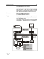
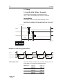
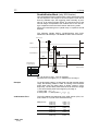
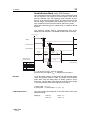
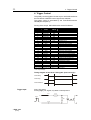
DoubleShutter Mode (only XD-Version)
Two separated full frame images with a short interframing time
can be captured. The length of the first exposure time will be
done by software input, the triggering either internally by software or by an external trigger signal. The exposure time of the
second image corresponds to the readout time of the first image. It depends of the used CCD sensor and binning mode.
During the interframing time td (dead time) no exposure should
be done
The following signals /BUSY, /CCD-Exposure and /CCDReadout are at the 26-pin. HD-DSUB socket of the PCI-Board.
External Trigger
/ BUSY
/ CCD-Exposure
/ CCD-Readout
Internal
Delay
Exposure
Image 1
Exposure
Image 2
Readout Time 1
Real exposure
on CCD sensor
tdi
texp1
tj1
tj2
tj3
td
Image 1
Readout Time 2
Image 2
10...20µs
5µs...65ms
0...5µs
300...700µs
0...3µs
2µs
timing not scaled
texp1 can be set to 10µs...10ms by software.
exposure time of image 2 (texp2) = readout time of image 1
Example
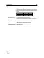
To set two laser pulses in a short time one after another (about
10µs), the following relation is valid. The timing of the first laser
pulse starts with the falling edge of /BUSY (respect. /CCDExposure). The first laser pulse must be set at the end of image
1, the second laser pulse at the beginning of image 2.
1. laser pulse = texp1 – tj1
2. laser pulse = 1. laser pulse + tj1 + (td + tj3 )
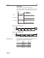
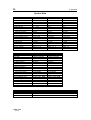
CCD Readout Time
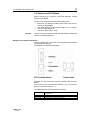
The CCD readout time depends of the CCD sensor (VGA, Scientifi, HiRes or UV) and of the selected binning:
VGA (200/205)
VGA (210/215)
Scientific
HiRes / UV
©PCO 2006
pixelfly
V1-Binning:
V2-Binning
V4-Binning
V1-Binning:
V2-Binning
V4-Binning
V1-Binning
V2-Binning
V1-Binning
V2-Binning
19,8ms ± 0,5
10,3ms ± 0,5
5,6ms ± 0,5
24,8ms ± 0,5
12,8ms ± 0,5
6,8ms ± 0,5
79,8ms ± 0,5
40,3ms ± 0,5
104,0ms ± 0,5
52,5ms ± 0,5