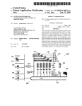
1
Automatization in the Design of Image Understanding Systems
Bernd R a d i g
W. Eckstein 2, K. Klotz 2, T. M e s s e r 1, J. Pauli 2
1 Bayerisches Forschungszentrum fiir Wissensbasierte Systeme
2 Institut ftir Informatik IX, Teclmische Universit~it Miinchen
Orleansstral~e 34, D-8000 Miinchen 80
Abstract. To understandthe meaningofan imageor imagesequence,to reducetheeffortin thedesignprocessand increasethereliabilityandthereusabilityofimageunderstandingsystems,a wide
spectrum of AI techniquesis applied. Solvingan imageunderstandingproblem correspondsto
specifyingan imageunderstandingsystem whichimplementsthe solutionto the givenproblem.
Wedescribean imageunderstandingtoolboxwhichsupportsthe designof suchsystems.The toolbox includeshelpand tutormodules,an interactiveuserinterface,interfacesto commonprocedural and AI languages,and an automaticconfigurationmodule.
1
Introduction
Machine Vision, and in general the interpretation of sensor signals, is an important field of Artificial Intelligence. A machine vision system coupled with a manipulator is able to act in our
real world environment without the human being in the loop. Typical tasks of understanding
the semantics of an image involve such applications as medical diagnosis of CT-images, traffic monitoring, visual inspection of surfaces etc. Given an image understanding problem to be
solved for a specific application, usually a long process of incremental design begins. A huge
space of parameters and decisions has to be mastered to achieve satisfying results. Illumination conditions, if they are under control, have to be experimentally set. Operators acting on input images and intermediate results have to be selected. The procedures implementing them
are usually further specified by individual sets of parameters. Appropriate data structures have
to be invented which somehow correspond to the image structures which have to be computed.
The search space of interpretation hypotheses has to be managed and hypotheses have to be
evaluated until a final result is obtained.
No theory of Machine Vision exists to guide the design of an image understanding system and
the methodological framework to support the design is not sufficiently developed. Therefore,
to improve the efficiency of the design process and the quality of the result, tools have to be utilized which offer support for the different phases of the design process of an image understanding system. Most of those which are available now concentrate on fast prototyping of
low-level image processing. Older tools merely consist of FORTRAN or C libraries (e.g. SPIDER [Tamura et al. 83]) of modules which implement typical signal and image processing operators, e.g. filters. Newer ones supply front ends which use some window-mouse based interaction, e.g. [Weymouth et al. 89]. A CASE-tool for constructing a knowledge based machine
vision system will not be available in the near future. Nevertheless, some of the limitations of
existing tools can be overcome by directing research into those phases of the design process in
which parts can be operationalized and therefore incorporated into a next generation of those
tools [Matsuyama 89], [Risk, B0mer 89], [Vernon, Sandini 88].
36
2
Computer Aided Vision Engineering
In solving a machine vision problem, an engineer follows more or less a general life-cycle
model. He has to analyse the problem, collect a sample of typical images for testing, specify a
coarse design on a conceptual level, match this design with available hardware and software
modules, specify and implement some missing functionality, realize a prototype, perform
tests using the collected set of images, improve the prototype, observe more and more constraints which accompany the transfer into real use, specify and implement the final system,
validate the system using a different sample of images, monitor the system during operation,
and do final modifications. In the first part of the life-cycle, to perform a feasibility study, fast
prototyping is the usual strategy. Experience tells that in reality even for not to complex problems prototyping is slow. This was our motivation to start building a toolbox which supports
machine vision engineering, especially suited for feasibility studieS. As a consequence of this
focus, we omitted those parts which could handle real-time and process control requirements
but concentrated on solving the image understanding problem.
2.1 Toolbox Properties
A toolbox supporting fast prototyping should have some of the following properties:
Sensor Input and Documentation Output Control. A wide variety of sensors may be utilized to take images and image sequences, e.g. CCD-camera, satellite, scanner etc., which deliver various image formats. Also a variety of display and hardcopy devices is in use, e.g. film
recorder, colour-displays, black-and-white laser printers and the like. The toolbox should accept input from usual sources and produce output for usual display and hardcopy devices as
well as for desktop publishing systems.
Repertoire of Operators. The core of a toolbox are efficient operators which manipulate and
analyse images and structural descriptions of images, e.g. affine transformations, linear filters, classifiers, neuronal networks, morphological operators, symbolic matching methods
etc. If the toolbox provides uniform data structures and their management together with preformed interfaces, new operators can be easily incorporated. They should be written with portability in mind so that they can be transferred later into the target system and are reusable in
other toolbox versions.
Data Structures. The concept of abstract data structures has to be implemented to hide implementation details and to allow programming in different languages, e.g. C, C++, Pascal, PROLOG, LISP, and even AI shells to access these structures.
System Architecture. Typical modules in a toolbox should be the internal data management
system, an external image database management system, device drivers, operator base, network communication subsystem to allow for remote access and load sharing within a distributed environment, procedural interface with extensions specialized for each host language,
graphical user interface, command history with undo, redo, replay facilities, online help, advice and guidance module, automatic operator configuration module, knowledge acquisition
tool including editors for different forms of knowledge description and a consistency checker,
and a code export manager which generates source or binary code for the operators and data
structures, used in the prototype for compilation and linking in the target environment.
2.2 Goals
Portability. To save investments into software, as well into the target systems as into the toolbox itself, such a system must be highly portable and has to generate reusable code for the target system. A UNIX environment for the toolbox and eventually for the runtime system, too, is
the current choice. The user should not been forced - as far as possible - to invest time in integrating different hardware and software concepts and products before being sure that his idea
37
of a problem solution will work.
Uniform Structures. If on all levels of an image understanding development system- signal
processing through symbolic description - functions and data structure are presented in an uniform way which hides most implementation details, the user is motivated to explore even
apparently complex constructs of operator sequences. He can easily combine and switch
between different levels of abstraction in his program, focussed on functionality, on what-todo and not on how-to-do it.
Interaction. This motivation has then to be supported by an highly interactive, "user friendly"
toolbox interface which stimulates the engineer to test alternatives and not to think from the
very beginning in terms of technical details and implementation effort.
Tutorial, Tactical and Strategical Support. Of the user, especially anovice one, it cannot be
expected that he is able to keep the functionality, applicability, and parameters of all image
analysis methods, cast into operators and sequences of them, which the toolbox can offer in his
mind. Therefore a tutorial, tactical and strategical support is a must. He needs advice what
operators to select, what alternatives exists, how to determine parameter values for their arguments, time and space complexity to be expected, and how to optimize if the prototype does
not produce acceptable results.
Automatic Configuration. If the toolbox has some knowledge about the methods included in
its operator base, automatic configuration becomes available. If at least a partial image understanding problem can be described in a formal way or even better by demonstrating examples
and eventually counterexamples of what kind of image feature has to be detected, a configuration module could be able to choose an optimal sequence of optimal parameterized operators
automatically from the operator base. First results in this direction are reported by [Ender 85],
[Haas 87], [Hasegawa et al. 86], [Hesse, Klette 88], [Ikeuchi, Kanade 88], [Messer, Schubert
91], [Liedtke, Ender 89].
Automatic Adaption. If (a part of) an image understanding problem is given by supplying a
generic model e.g. of the real world object to be detected or by showing representative exampies it becomes essential to guarantee the transfer the problem solution based on this description to the real operation of the final system. To do this with a minimum of the engineer's intervention, an automatic adaption or specialization of the generic description to the varying situations during operation has to be included into the design of the toolbox which in tum has to
include this capability into the runtime system [Ender, Liedtke 86], [Pauli et al. 92].
Competence Awareness. If a machine vision system is able to adapt itself to (slightly) varying conditions it should be able to detect when its limited capabilities to follow changing situations is exceeded. To be able to report this is a prerequisite for controllable reliability. Then it
can ask for human intervention, from manual parameter tuning through a complete redesign,
to analyse and handle such situations.
We do not believe that it is an easy task realizing a machine vision toolbox those properties
striving at these goals. Automatic design and programming of problem solutions is a dream.
Nevertheless, in such a special environment as image understanding is, methods of knowledge
engineering, software engineering, and life-cycle support may b e - with greater success than
in general data processing - combined into a form of computer aided vision engineering,
CAVE.
3
The HORUS Project
About five years ago, we started building two alternatives of tools intended to support research
and education in image processing and understanding. One based on special hardware (digitizer, display system, Transputer board .... ) and special software (OCCAM) which required
high competence in hardware and software engineering to become operational and to be main-
38
tained. This concept
survived in a spin-off
company of the author.
The weak point with
this approach is the
intensive use of hardware dependant implementation and therefore the costly adaptation to technical innovations.
The other alternative
aimed at realizing some
of the properties and
goals as described in
Chapter 2.
Portability: As hardware platform for the
HORUS toolbox a genetic UNIX workstation environment was
chosen, using standard
C as implementation
language, TCP/IP protocols for communication, and XWindows and OSF/Motif to interact with the user [Eckstein 88a], [Eckstein 90]. The interfaces to the operating
system are so well defined and localized that it has been
transferred- with an effort of two hours through one d a y to different platforms such as DECStation Ultrix, even
DECVAX VMS, HP9000 family, SUN Spare, Silicon
Graphics family, and even multiprocessor machines such
as Convex and Alliant.
Load Sharing. If more than one processor is available in a
workstation network or a multiprocessor machine, execution of operators can automatically be directed to aprocessor which has capacity left or which is especially suited,
e.g. a signal or vector processor. The interprocess communication uses standard socket mechanisms, the load situation is monitored using Unix system commands [Langer,
Eckstein 90].
Fig. 2. Sub windows
class_2dlm
[ class_ndi.1
[ class_ndi~2
[ dgn_ttmeshold
]
]
]
]
[
]
~t~r-~l~_t~os~ld]
Interaction. A typical screen using the interactive version
of HORUS looks as in Fig. 1. The user starts with the main
menu (sub window 2 in Fig. 2) where he may open sub
[ l~,_to_obJ ]
window 8 to create or modify windows to display pictures
or text, sub window 4 (see Fig. 3) to see a list of operators
[ le.~Y'n_ndlml
(organized in chapters) which are contained in HORUS,
sub window 7 (see Fig. 4) to set parameters, sub window 1 to see a directory of
images or image objects he hasused and
produces in his session, or other windows to call the online help and manual,
!'~'1 Im
~tto
II
,,,-,gi,~l
select input and output devices etc. Fig.
4 shows an example of the variety of
parameters which control the display of
Fig. 4. Default window parameters for image display
]
39
an image, in this example 3 colours,
raster image, line width 1 pixel in
white colour, default lookup table,
default presentation (optimized for
the screen), original shape, and display of the whole picture without
zooming etc. Since HORUS knows
which screen is in use, this menu
automatically offers only such
parameter values which are needed
and applicable.
High Level Programming. The
engineer may choose the interactive
exploration to get some feeling about
which operators to apply in which
sequence. A history of commands is
logged which can be modified and
executed
again.
Furthermore,
HORUS offers a comfortable host
language interface which allows the
engineer to program his solution in a
procedural (using C or Pascal as language), functional (LISP), object
oriented (C++) or declarative (PROLOG) style [Eckstein 88b].
As an example a PROLOG (see Fig.
7) and an equivalent LISP program
(Fig. 8) are given
which solve the task
of finding on a thick
film ceramic board
areas which are not
covered correctly
by solder (Fig. 5, 6).
The basic idea is to
illuminate the board
from four sides in
such a way, that the
highlights form the
contours of the lines
where these are
40
covered by solder. The solution is
then straightforward.
-11~
By thresholding all pixels with an
intensity value lower than 70 (this
can be determined interactively)
in each image L, R, O, U, an object
Dark is obtained which contains
r/~"a I I
11
four components of dark areas. A
I I1~,................~/
union of these four pixel sets representing the lines is formed. Low
Fig. 10. Missing solder on
pass filtering, dynamic thresholdFig. 9. Highlights from four
black regions
ing, and set union produces the
images
contour image of Fig. 9. The
threshold parameter is also selected by an interactively controlled test. The regions which are
enclosed by contours are filled, forming a cover of all lines except where solder is missing.
Subtracting this result from the object Line uncovers those areas. The remaining pixels are
collected and connected regions are formed. Regions with an area of less than 20 pixels are
excluded and the result is stored in the object Fault which is displayed in Fig.10.
m m
The LISP program is a transcription of the PROLOG program. The data structures are objects
which have hidden components created and
selected automatically by operators. This kind of
abstraction allows the engineer to write compact
programs without being involved in implementation details.
m m
ml~,.m
m.ll~
HIll%
kor.r-,~eI t ~ .
~o~rl~xltv:
[
............................
--.I
Fig. 11. Error related window: information
about operator
EK3
,dll.dI . t , t 1 , ~
di,,I D,l,,t,~,l 4~" E , , ~ , , , l ~
ll.l;~ l..,tAr ll~(,..~.,(Li..kin la.lp..lt ~
open access to related topics, e.g. description of operators with similar functionality
or explanation of the meaning of the word
threshold. The button parameter tells how
to choose parameter values for this operator, the button abstract delivers a short
description and the button manual gives a
long description of the operator (Fig. 12).
The manual is written in LATEX, therefore
a standard UNIX tool has been used to provide the functionality of the manual management and a LATEX preview program
generates the window. A new version will
use a Postscript previewer which allows
the inclusion of pictorial examples and
Ifl,x~|
dllitlonl llqfflrt ~ n ~ltt T~II[, /+111 dto rrM~t~'
Help Modes. Operators perform exception handling to inform the user. A window is opened which
displays related information (Fig. 11). Here the
name of the operator where the error occurred is displayed. The bottom part of the window explains
which result is generated and which errors arise in
what situation, in this case dilation on an
empty image. In the upper part of the window, a menu offers related information.
Pressing the help button gives an explanation how to use these menus. The buttons
keywords, see_also, and alternatives
Inlll+l*l~
m
~ ,
9
..~
V.,,'~'t"k"l~
t ~ ' D i',t"l~'~ ~
~, 4t....~k.l ~k.,~.~,~.i.k~m.--Wk'.r .. = 14,.~1
,
,dl~&*4k~14R,M } ~ ~ r~lR !
'
-
m
.
w
r-~
r-~
r-~
~n,~k..,,1
sJR.z Au ~.:
[-~
~.ulu.l,tJu~
- ~
9
;,
t
,
9
."
;<
,
",.'
:
""
~at~alxt~
Fig. 12. Section of the online user manual
41
explanations into the manual.
In combination with PROLOG as the host language, the help module is currently enhanced by
more functionality. One direction is to help the
user to understand why an error occurred. It traces
back the chain of PROLOG clauses to identify the
place where a chain of computations and operator
applications caused the generation of an invalid
situation. Here debugging can be done on the same
abstract level as programming.
Iflul
Tt~lll
HRRUS-KapItnI:
~v,te!
Flits"
G'q'3hik
Klal~lFtluJl;lorl
~tze
0b.ilkt
Ses,~mt4ti~
Info
C.tr teace
IllRIJ~-.Praedlkete:
crlultmJ~pfleld
create.kt~t~n
d~r
do~l~rlpt.e]lllll r2
dwlgllm
dtff_or
diletl(~2
dl lit tl:,.Ltmlail
d[ Ill;ll~.wq
dlr~tlaqt
__ II
~Jt,,~f-Preed I kat,e:
l'~lt
In|i; I lo
(lx)
Init, I 2,
(11)
The other direction is to analyse the actions which
kleirmda~rtlkeI / 2.
(1
.erke / 1o
(2x)
the user has performed during a session in the
L
I!1
PROLOG and in the HORUS system [Klotz 89].
Here the help systems monitors the user input and
is therefore able to give more precise advice in
: a i ~ i t (exliple ~
I 3
case the user needs help or an error message comes
up. A first step in the realisation of this concept is
the module operated by the window of Fig. 13. It
Hler It0R~-lF/Prolol~omardos elr~enl
provides the user with a complete list of predicates
P
14
he has defined in field 2 and HORUS operators in
field 1 which are from the point of view of PROFig. 13. HORUS! PROLOGdebuging
LOG built-in predicates. Field 3 displays the history of actions which are available for inspection, modification and redo application. Field 4
accepts as input PROLOG and HORUS commands which are performed in the current context
of execution. Similar concepts of debugging are well known from several LISP systems and
applications. The innovation here is the uniform handling of actions in PROLOG as well as in
HORUS. Further development will include the automatic analysis of interaction protocols to
guide the user in understanding why an error occurred. Traces of rule activations and procedure calls as well as the assignment of variables at the moment when the error occurred will be
available. The idea is to give the user a meaningful access to all those objects which might be
associated with an exception, and to suggest alternatives for control structure and parameter
values.
Automatic Configuration. The
online manual contains all information about HORUS operators which
are needed for advice and guidance.
Using this information, represented
in a frame-based knowledge base
[Polensky, Messer 89] together with
basic knowledge of image processing, the module FIGURE [Messer
92a,b] is able to automatically generate image interpretation algorithms
which are composed of operators
from the HORUS operator base. In
the current version, the configuration
module is given an example of that
kind of objects it should detect in an
image or a sequence. This can be
done interactively, e.g. using the
mouse to indicate the region where
the object is, or by some simple segmentation method. In the application
illustrated in Fig. 14 the pins of the
42
Ja - ~. :,~,
~-:..z,a.r --zaa
.....
integrated circuits have to be detected. FIGURE analyses the
boundary, the background surrounding the object, and its interior. It then constructs a search space of all reasonable operators
which might be applied. Various rules and constraints restrict the
search space to a manageable size. Static restrictions help to
determine the order of operators within the algorithm to be constructed. An example of such arule is:If dynamic thresholding is
J~
'~"~
selected then it should be preceded by smoothing. The even ~~./~k ~-t~" !'~ :
more difficult task is to supply the modules with values for their ~, l~.il~ ;'1;.'..|I llill,;~i! I I,YJII i:"~
parameters. Elementary knowledge about computer vision is
included in the rule base as well as operator specific knowledge.
Fig. 15. Small bright spots
No domain specific knowledge is incorporated in the rule base.
detected by operator
These rules are rather simple, telling the system such elementary
sequence
first configured
statements as for edge preserving smoothing a median filter is
better than a low pass filter. Constraints between operators forbid e.g. applying a threshold operator on a binary image. But
from the operator specific knowledge the system knows that a
threshold operator needs a threshold value between I and 255.
The quality of the generated proposals of operator sequences
depends not only on the knowledge base but even more on the
precision with which a vision problem can be described and the
sequences can be evaluated. Of course, there is a correlation
between both. Since at the moment a problem is described by
indicating the boundary of a region which has to be extracted,
two aspects are used for evaluation. The evaluation function
takes into account how good the area of the found object matches
the area of the given object and the distance between the boundaries of both objects. To force the configuration system to generate altemative sequences which include different operators in
their sequences and not only different parameter values for
essentially the same sequence, two templates are
generated from the indicated boundary, namely a
boundary oriented and aregion oriented one. The
best of both altematives generated for these two
classes survives.
As an example consider the problem of detecting
the pins of integrated circuits on a printed board
as in Fig. 14. One pin's boundary is drawn, e.g. the
one indicated by an arrow in Fig. 14. The configuration system generates an operator sequence
which detects correctly most of the pins but also a lot of other
small regions. The simple remedy is to filter out all regions
which are not close to the body of the IC. Therefore, the detection
oflC bodies is given as a second task to the configuration system.
Fig. 16 shows the result. The closeness constraint cannot be
implemented in the current version. The vision engineer has to
do some programming, formulating such code as in Fig. 17. The
arguments to the simple PROLOG rule are both images as inputs
and the resulting image as output. For the IC bodies the contours
of their convex hulls are computed. A circle of radius 5 pixels is
defined and used to widen the contour, implementing the predicate close. A simple intersection of this image with that of the
small regions eliminates most of the unwanted spots.
It is obvious from Fig. 18 that the result is not completely correct.
|il
.
I
Figd~Cg~~
i
'""
i'"*
I
._l
~ nd
I
. . . . . .
1'i
-. ~ ; - .
.
,
.-.
-i ~ ,
Fig. 18. Spots close to IC
boundary, combined from
both results, mostly pins
!
43
Anyhow, the automatic configuration is utilized
here in the context of rapid prototyping. The result
gives a good starting point to improve on. To prepare
this example for this paper took less than one hour. It
could be done on a very abstract but natural level in
terms of design decisions such asfind small bright
regions close to IC bodies. Two mouse interactions
and one PROLOG rule implemented it.
Model Adaptation. The models for describing
objects, used so far, are simple closed contours. This
is, of course, not sufficient for the analysis of more
complex situations [Liedtke, Ender 86] where
scenes are to be composed of objects constructed as
a part-of hierarchy and related by constraints
[Fickenscher 91 ]. The more complex such models are the more difficult
it will be to attempt a generalizable description. A typical situation
exists in an image sequence with moving objects [Nitzl, Pauli 91 ]. Here
the model of an region in each image has to follow the expected or predicted changes. Varying attributes are area, boundary, shape, greyvalue, position, contrast to background etc. as well as relations such as
below, darker, between, inside etc. In the example of Fig. 19 which
shows the first frame of a sequence, a man is moving his right leg. A
part-of hierarchy can easily be constructed, guided by the segmentation
result of Fig. 20. A model of the right leg is obtained by specifying an
elongated nearly vertical region whose centre of gravity is left of a similar region, both connected to a more compact region which is above.
Fig. 22 consists of an overlay of Fig. 20 and the isolated right leg in different positions.
For matching the model with the image structure, maximal cliques
(totally connected subgraphs) in an assignment graph are computed
[Radig 84]. The nodes of the assignment graph are formed from potentially corresponding pairs of image and model elements. Edges in this
graph link relational consistent assignments. This approach is able to
establish correspondence even in the case of deviations of relation and
attribute values. To match image and model structure is a NP-hard
problem. Application of heuristics using some kind of A*-search techtuque reduces complexity [Pauli 90]. Other techniques of matching
structures are presented in [Pfleger, Radig 90]. The problem of how to
evaluate the quality of the match has received much attention in the last
decade. A recent workshop on Robust Computer Vision [Ftirstner,
Ruwiede192] discussed different approaches.
0
Fig. 20. Initial segmentation
Fig. 21. Right leg
0
A major problem, solved only for simple situations, is the specification
of tolerance parameters to attribute values given their interdependence
by the relations which exists between different elements. It is impossible to describe analytically e.g. how the height and width of the rectangle circumscribing the leg in Fig. 22 varies with the motion. The length
Fig. 22. Leg in
of the boundary of the right leg is somehow related to the area of the
motion
enclosed region but impossible to state exactly. Even if for some relationships an exact dependency might be found, it usually becomes corrupted by the unreliability of the image processing methods, by noise, or by the effects of digital geometry on the rastered image. Therefore, variations of attribute values which should be tolerated by the matching process are not easily determined and need time consuming experimentation. The model
adaptation module, to be enclosed in the HORUS toolbox, contains methods of qualitative
reasoning to help the engineer determining trends of parameter values and to follow difficult
interrelationships without violating consistency between those parameter tolerances.
44
4.
Conclusion
After more than twenty years of image understanding research the situation with respect to the
methodology of designing image understanding systems is disappointing. A theory of computational vision still does not exists which guides the implementation of computer vision algorithms. Our approach originated from an engineering point of view. We identified some of the
problems which decrease quality of the results and productivity of the design process in the
area of image understanding. Obviously, we could not address all aspects and could not offer
solutions to all the problems we are faced with.
Our advantages in the problem areas of portability, user interfacing, paraUelisation, multi host
language interfacing, tutorial support, high level debugging, model adaptation, reusability,
and automatic configuration are sufficient to start integrating all related software modules in a
toolbox for Computer Aided Vision Engineering. In the HORUS system the availability of an
interactive and a high level programming interface, the online help and debugging system, and
the automatic configuration module have been in use for some period of time. We use it extensively in a practical course on Computer Vision as part of our Computer Science curriculum.
We observed a drastic increase of creative productivity of our students working on their exercises. Other Computer Vision Labs testing our system reported a similar experience.
In the near future the model adaptation will be more closely integrated into HORUS. The tutorial module will be able to give recommendations to the designer which module and parameter
values to c h o o s e - an interactive complement of the automatic configuration module. During
the process of integration some new challenges will appear. One is the extension of the internal
object data structure - which is effective and efficient for low- and medium-level processingto structures needed by high-level image understanding. A second problem is the description
of operators in such the way that all modules are able to extract automatically that part of the
information which it needs. To describe more than 400 operators ranging from a simple linear
filter up to a complete Neural Network simulator is a time consuming task. To specify formally for an author of a new module how he has to encode for HORUS the knowledge about
his operator is not solved in general.
Nevertheless, we could demonstrate that some parts in the design process of image understanding systems can be automatized successfully.
References
[Eckstein 88a]: W. Eckstein: Das ganzheitlicheBildverarbeitungssystemHORUS, Proceedings 10thDAGM
Symposium 1988, H. Bunke, O. Kiibler,P. Stucki (Eds.), Springer-Verlag,Berlin 1988
[Eckstein 88b]: W. Eckstein: Prologschnittstellezur Bildverarbeitung.Proceedings 1st IF/PrologUser Day,
Chapter 5, Miinchen,June 10, 1988
[Eckstein90]: W. Eckstein: Reporton the HORUS-System. INTER,RevueInternationalde L'Industrie et du
Commerce, No 634, Oct. 1990,pp. 22
lender 85] M. Ender:Designand Implementationof an Auto-ConfiguringKnowledgeBased VisionSystem,in:
2nd International Technical Symposium on Optical and Electro-Optical Applied Sciences and
Engineering, ConferenceComputerVision for Robots, Dec. 1985, Cannes
[Ender, Liedtke 86]
M. Ender, C.-E. Liedtke: Repr'~entationder relevantenWissensinhalte in einem selbstadaptierenden
regelbasierten Bilddeutungssystem,Proceedings 8th DAGM-Symposium 1986, G. Hartmann (Ed.),
Springer-Verlag, Berlin 1986
[Fickenscher91] H. Fickenscher:Konstruktion von 2D-Modellsequenzenund -episodenaus 3D-ModeUenzur
Analyseyon Bildfolgen,TeclmischeUniversit~tMiinchen,InstitutfiirInformatikIX, Diplomarbeit,1991
lF~Srstner,Ruwiedel 92] W. F6rsmer, R. Ruwiedel (Eds.): Robust Computer Vision, Proceedingsof the 2nd
45
International Workshop, March 1992 in Bonn, Herbert Wichmann Verlag, Karlsruhe 1992
[Haas 87] L_I. de Haas: Automatic Programmingof Machine Vision Systems, Proceedings 13th Intemationai
Joint Conference on Artificial Intelligence 1987, Milano, 790 - 792
[Hasegawa et al. 86] J. Hasegawa, H. Kubota, J. Toriwaki: Automated Construction of Image Processing
Procedures by Sample-Figure Presentation, Proceedings 8th International Conference on Pattern
Recognition 1986, Paris, 586 - 588
[Hesse, Klette 88] R. Hesse, R. Klette: Knowledge-BasedProgram Synthesis for Computer Vision, Journal of
New Generation Computer Systems 1 (1), 1988, 63 - 85
[Ikeuchi,Kanade 88] Katsushi Ikeuchi,TakeoKanade: AutomaticGenerationof Object RecognitionPrograms,
Proceedings of the IEEE, Vol. 76, No. 8, August 1988, 1016 - 1035
[Klotz 89] K. Klotz: Uberwachte Ausfiihrungvon Prolog-Programmen.Proceedings 2nd IF/Prolog User Day,
Chapter 9, Miinchen,June 16, 1989
[Langer, Eckstein 90]: W. Langer, W. Eckstein: Konzept und Realisierungdes netzwerkf'~h~igenBildverarbeitungssystemsHORUS, Proceedings 12thDAGM-Symposium,R. E.. Grol]kopf(Ed.), Springer-Verlag,
Berlin 1990
[Liedtke, Ender 86] C.-E. Liedtke, M. Ender:A KnowledgeBased VisionSystemfor the AutomatedAdaptionto
New Scene Contents, Proceedings8th InternationalConferenceon Pattern Recognition 1986,Paris, 795 797
[Liedtke, Ender 89] C.-E, Liedtke, M. Ender: WissensbasierteBildverarbeitung,Springer-Verlag,Berlin, 1989
[Matsuyama 89] T, Matsuyama: Expert Systems for Image Processing: Composition of Image Analysis
Processes, in: Computer Vision, Graphics, and Image Processing 48, 1989, 22 - 49
[Messer 92a] T. Messer: Model-Based Synthesis of Vision Routines, in: Advances in Vision - Strategies and
Applications, C. Archibald (ed.), Singapore, World Scientific Press, 1992, to appear
[Messer 92b] Tilo Messer: AcquiringObject ModelsUsing VisionOperations,ProceedingsVision Interface'92,
Vancouver, to appear
[Messer, Schubert 91 ] T. Messer, M. Schubert: Automatic Configuration of Medium-Level Vision Routines
Using Domain Knowledge, Proceedings Vision Interface '91, Calgary, 56 - 63
[Nitzl, Pauli 91] F. Nitzl, J. Pauli- Steuerungyon Segmentierungsverfahrenin Bildfolgen menschlicherBewegungen, Proceedings 13thDAGM-Symposium,Miinchen,B. Radig (Ed.), Springer-Verlag,Berlin, 1991
[Pauli90] J. Pauli: Knowledgebased adaptiveidentificationof 2D imagestructures; Symposiumof the International Societyfor Photogrammetryand RemoteSensing,SPIE ProceedingSeries, Band 1395, S. 646- 653,
Washington, USA, 1990
[Pauli et al. 92] J. Pauli, B. Radig, A. B10mer,C.-E. Liedtke: Integrierte, adaptive Bildanalyse, Report 19204,
Institut fiir Informatik IX, Technische Universi~t Miinchen, 1992
[Pfleger, Radig 90] S. Pfleger, B. Radig (Eds.): AdvancedMatching in Vision and Artificial Intelligence, Proceedings of an ESPRIT workshop, June 1990, Report TUM-19019,Technische Universitat Miinchen;to
be published by Springer-Verlag,Berlin 1992
[Polensky,Messer 89] G.Polensky, T. Messer:Ein Expertensystemzur frame-basiertenSteuerungder Low- und
Medium-Level-Bildverarbeitung,Procee.dings11th DAGM-Symposium89, Hamburg,H. Burkhardt,K.
H. HOhne,B. Neumann (Eds.), Springer-Verlag,406 - 410
[Radig 84] B. Radig: Image sequence analysis using relational structures; Pattern Recognition, 17, 1984, 161167
[Risk, B0rner 89] C. Risk, H. Borner: VIDIMUS: A Vision System Development Environment for Industrial
Applications, in: W. Brauer, C. Freksa (Eds.): WissensbasierteSysteme, Miinchen Oct. 1989, Proceedings, Springer-Verlag Berlin, 477 - 486
[Vemon, Sandini 88] D. Vernon,G. Sandini: VIS: A VirtualImage System for Image-UnderstandingResearch,
in: Software - Practice and Experience 18 (5), 1988, 395 - 414
[Weymouthet al. 89]T. E. Weymouth,A. A. Amini,S. Tehrani:TVS: An Environmentfor BuildingKnowledgeBased Vision Systems, in: SPIE Vol. 1095 Applicationsof Artificial Intelligence VII, 1989, 706 - 716