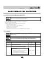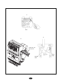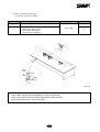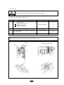
1
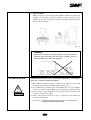
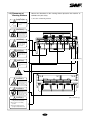
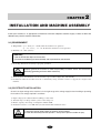
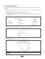
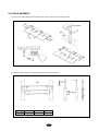
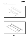
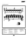
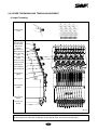
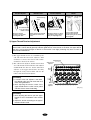
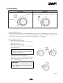
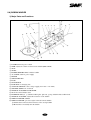
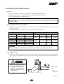
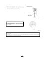
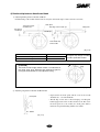
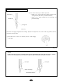
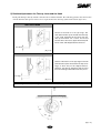
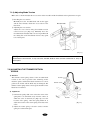
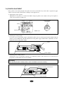
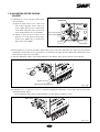
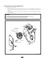
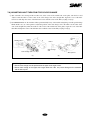
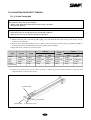
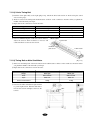
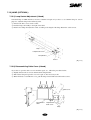
MANUAL
TWO-HEAD AUTOMATIC
EMBROIDERY MACHINE
FOUR-HEAD AUTOMATIC
EMBROIDERY MACHINE
SIX-HEAD AUTOMATIC
EMBROIDERY MACHINE
EIGHT-HEAD AUTOMATIC
EMBROIDERY MACHINE
SIX-HEAD AUTOMATIC
EMBROIDERY MACHINE
(Compact Type)
SWF/E-Series
MME-060809
SUNSTAR PRECISION CO., LTD.
1. THIS IS AN INSTRUCTION FOR SAFE USE OF
AUTOMATIC
EMBROIDERY MACHINES. READ THOROUGHLY BEFORE USE.
2. CONTENTS IN THIS INSTRUCTION MAY CHANGE, WITHOUT
PRIOR NOTICE, FOR IMPROVEMENT OF MACHINE QUALITY AND
THUS MAY NOT CORRESPOND TO THE MACHINE YOU
PURCHASED. CONTACT YOUR SALES AGENT FOR INQUIRIES.
3. THIS IS DESIGNED AND MANUFACTURED AS AN INDUSTRIAL
MACHINE. IT SHOULD NOT BE USED FOR OTHER THAN
INDUSTRIAL PURPOSE.
TABLE OF CONTENTS
CHAPTER 1
SAFETY RULES ................................................................................................................ 1-1
1-1) DELIVERY OF YOUR MACHINE........................................................................................1-1
1-2) INSTALLATION.....................................................................................................................1-2
1-3) MACHINE OPERATION ...................................................................................................... 1-3
1-4) REPAIR................................................................................................................................... 1-3
1-5) PLACEMENT OF WARNING STICKERS .......................................................................... 1-4
1-6) CONTENTS OF WARNING STICKERS ............................................................................. 1-5
CHAPTER 2
INSTALLATION AND MACHINE ASSEMBLY ............................................................ 2-1
2-1) ENVIRONMENT ................................................................................................................... 2-1
2-2) ELECTRICITY INSTALLATION ........................................................................................ 2-1
2-3) LEVELING THE MACHINE ................................................................................................ 2-2
2-4) ASSEMBLY OF PERIPHERAL DEVICES ......................................................................... 2-3
2-5) TABLE ASSEMBLY ............................................................................................................. 2-4
2-6) FRAME ASSEMBLY ............................................................................................................ 2-6
2-6-1) TUBULAR FRAME ............................................................................................... 2-6
2-6-2) BORDER FRAME .................................................................................................. 2-7
CHAPTER 3
PARTS OF THE MACHINE .............................................................................................. 3-1
3-1) SWF/E-U SERIES .................................................................................................................. 3-1
3-2) SWF/E-UH 1508-45 ............................................................................................................... 3-2
CHAPTER 4
FUNCTIONS AND FEATURES ....................................................................................... 4-1
CHAPTER 5
FUNCTIONS FOR BASIC MACHINE OPERATION ..................................................... 5-1
5-1) LAMP ON THREAD TENSION ADJUSTMENT BOARD ................................................ 5-1
5-2) NEEDLE STOP CLUTCH...................................................................................................... 5-2
5-3) LAMP ON COLOR CHANGE BOX(SWF/E-UH1508)........................................................ 5-3
5-4) UPPER THREADING AND TENSION ADJUSTMENT .................................................... 5-4
5-5) LOWER (BOBBIN) THREADING AND TENSION ADJUSTMENT ................................ 5-7
5-6) BOBBIN WINDER ................................................................................................................ 5-8
5-7) PRECAUTIONS IN USING FLOPPY DISKS OR USB MEMORY STICKS .................. 5-10
5-8) INSERTING FLOPPY DISKS AND USB MEMORY STICKS ........................................ 5-11
5-9) DELETING FLOPPY DISKS AND USB MEMORY STICK............................................. 5-11
5-10) READING AND WRITING OF EMBROIDERY DESIGNS ........................................... 5-11
5-11) RETURN TO PREVIOUS LOCATION IN UNEXPECTED BLACKOUTS ................... 5-11
5-12) NEEDLE-HOOK TIMING CONTROL .............................................................................5-12
5-13) ASSEMBLY AND FUNCTIONS OF THREAD DETECTOR ........................................ 5-17
5-13-1) FUNCTIONS OF THREAD DETECTOR ......................................................... 5-17
5-13-2) DISASSEMBLING THREAD DETECTOR ..................................................... 5-17
i
CHAPTER 6
MAINTENANCE AND INSPECTION ............................................................................. 6-1
6-1) CHECK POINTS FOR REGULAR INSPECTION .............................................................. 6-1
6-2) CLEANING ........................................................................................................................... 6-1
6-3) OIL SUPPLY ......................................................................................................................... 6-3
6-4) DRIVE BELT TENSION ....................................................................................................... 6-8
CHAPTER 7
MACHINE ADJUSTMENTS ............................................................................................ 7-1
7-1) ADJUSTING THE TRIMMERS ........................................................................................... 7-1
7-1-1) ADJUSTING THE POSITION OF THE TRIMMING CAM
(INSERT ANGLE OF MOVABLE BLADE) ........................................................ 7-1
7-1-2) ADJUSTING BLADE TENSION .......................................................................... 7-2
7-2) ADJUSTING THE TRIMMER RETURN SPRING ............................................................. 7-2
7-3) ADJUSTING UPPER THREAD HOLDING UNIT ...............................................................7-3
7-4) PICKER ADJUSTMENT ...................................................................................................... 7-4
7-5) ADJUSTING UPPER THREAD HOLDER .......................................................................... 7-5
7-6) ADJUSTING LOW-NOISE PRESSER FOOT ...................................................................... 7-6
7-7) RELATIONSHIP BETWEEN PRESSER FOOT AND NEEDLE ........................................ 7-7
7-8) CORRECT POSITION OF NEEDLE .................................................................................... 7-8
7-9) ADJUSTING HALF-TURN FILM FOR COLOR CHANGE ............................................... 7-9
7-10) JUMP MOTOR ADJUSTMENT ....................................................................................... 7-10
7-11) ADJUSTING DRIVE BELT TENSION ............................................................................ 7-11
7-11-1) Y-AXIS TIMING BELT ..................................................................................... 7-11
7-11-2) X-AXIS TIMING BELT ..................................................................................... 7-12
7-11-3) TIMING BELT ON MAIN SHAFT MOTOR .................................................... 7-12
7-12) LAMP (OPTIONAL) ......................................................................................................... 7-13
7-12-1) LAMP SOCKET ADJUSTMENT (4-HEAD) .................................................... 7-13
7-12-2) DISASSEMBLING CABLE COVER (4-HEAD) .............................................. 7-13
CHAPTER 8
TROUBLESHOOTING ..................................................................................................... 8-1
CHAPTER 9
BLOCK DIAGRAM .......................................................................................................... 9-1
ii
CHAPTER
1
SAFETY RULES
The following set of safety rules categorized as DANGER , WARNING , and CAUTION indicates possibilities of
physical or property damages if not fully observed.
DANGER : These safety instructions MUST be observed to be safe from danger when installing, delivering, or
repairing the machine.
WARNING : These safety instructions MUST be observed to be safe from machine injuries.
CAUTION : These safety instructions MUST be observed to prevent predictable machine errors.
1-1) DELIVERY OF
YOUR MACHINE
DANGER
ONLY TRAINED AND EXPERIENCED PERSONS, FAMILIAR WITH THE
RELEVANT SAFETY INSTRUCTIONS, SHOULD HANDLE THE MACHINE.
MAKE SURE TO FULLY OBSERVE THE FOLLOWING INSTRUCTIONS.
1) Using a crane
Make sure that the crane is large enough to hold the machine. Use a nylon
rope of sufficient strength. Place a wooden block at either side of the
machine before tying the rope. The angle should be 40°∆ or less. Make sure
that the rope does not touch the table.
nylon rope
※ Make sure all persons
and obstacles are out
of the way of the
moving equipment.
wooden block
[Fig.1-1]
1-1
2) Using a Forklift
Make sure that size and weight of the forklift is sufficient to support the
machine. Use the pallet to place the machine so that its center is on the
forklift arm (see [Fig.1-2]). Lift the machine carefully so that the machine
does not tilt to either side.
[Fig.1-2]
[WARNING]
Make sure to maintain the weight balance in machine deliveries,
especially when unloading the machine from a forklift or crane, in
order to prevent injury or machine damages.
1-2) INSTALLATION
CAUTION
Installation environment may incur machine malfunction or breakdown.
Make sure to meet the following conditions.
1) The foundation under the machine, i.e. table or desk, must be strong enough
to support the weight of the machine (approximately 1 ton).
2) Air conditioning can eliminate dust and humidity that can cause pollution
and corrosion of the machine. Make sure your machine is regularly cleaned.
3) Long exposure to direct sunlight can cause the paint of the machine to fade
or change of the machine shape.
4) Allow at least 50cm (20 inches) of space on each side of the machine for
convenient maintenance.
※ Please refer to 2. Machine Installation and Assembly for installation details.
1-2
1-3) MACHINE
OPERATION
The SWF Automatic Embroidery Machine is designed for applying
embroidery to fabric and other similar materials.
Pay careful attention to the WARNING and CAUTION stickers on certain
parts of the machine. Make sure to observe the following when operating
the machine:
WARNING
1-4) REPAIR
01) Read thoroughly and fully understand the manual before operating the
machine.
02) Dress for safety. Long and unbound hair, jewelry such as necklaces,
bracelets, and wide sleeves can get caught in the machine. Wear shoes
with non-slip soles.
03) Clear all persons from the machine before turning on the power.
04) Keep your hands or head away from the moving parts of the machine such
as needle, hook, take-up lever, and pulley when the machine is in
operation.
05) Do not remove the safety cover on the pulley or shaft when the machine is
in operation.
06) Be sure the main power is turned off and the power switch is set to OFF
before opening the cover of any electrical component or control box.
07) Be sure the main switch is OFF before manually turning the main shaft.
08) Turn the machine off when threading needles or inspecting the finished
embroidery.
09) Do not lean against the cradle or place your fingers near the guide grooves
of the frame.
10) The machine noise may exceed 85db when it is run at a maximum speed.
It is not higher than the standard level, but you may need earplugs or
sound-proof facilities for the operator and other workers.
Only SWF-trained and selected repair engineers should do repair work.
1) Turn OFF the power before cleaning or repairing the machine. Wait for 4
minutes so the machine electricity is completely discharged.
DANGER
[CAUTION]
It takes about 10 minutes after turning off the main switch before the
electricity is fully discharged from X/Y main shafts and the drive box.
2) Do not change the settings or any parts on the machine without
confirmation from SWF. Such change may cause safety accidents.
3) Use only SWF parts when repairing your machine.
4) Replace all safety covers when you are finished with your repair.
1-3
1-5) Placement of
Warning Stickers
Observe the directions on ALL warning stickers placed on the machine as
reminders for your safety.
1) Location of Warning Stickers
CAUTION
Open the upper shaft cover of
each head and supply the
designated oil.
WARING
Fire or death may be caused by
high voltage electric shock.
Don’t open the cover except for
service man assigned by SWF.
When open the cover turn off
power and wait for 6 minutes.
WARING
Injury may be caused by winding.
Be sure to turn off the power
before cleaning, lubricating,
adjusting or repairing.
WARING
Physical damage may be
caused by winding.
Don’t put your hands near the
arrow while the main shaft is
rotating
[Fig.1-3 Front]
WARING
Physical injury may be caused
by crevice.
Don’t put your finger in a groove
on the table.
WARING
Injury may be caused by moving
needle.
Ensure that the machine is in a
stop condition before changing,
threading or rethreading of
needies or changing of needles.
WARING
Physical damage may be caused
by interposition.
While embroidery frame is running
according to the direction of
embroidery frame may be injured
your hands by gap between fixed
body and embroidery frame.
WARING
[Fig.1-4 From top]
① Turn off the main power before
rotating the main shaft by hand!
② Do not remove covers during
operation!
③ Turn off the main power before
opening electricity-related boxes!
1-4
1-6) Contents of
Warning Stickers
1) Warning
ⓐ
WARNING
Injury may be caused by winding.
Be sure to turn off the power before
cleaning, lubricating, adjusting or
repairing.
[ Notice ]
“Safety cover”in the‘WARNING’refers to all covers
near the operating parts of the machine.
ⓑ
WARNING
Injury may be caused by moving
needle.
Ensure that the machine is in a stop
condition before changing, threading or
rethreading of needies or changing of
needles.
ⓒ
WARNING
Fire or death may be caused by high
voltage electric shock.
Don’t open the cover except for service
man assigned by SWF.
When open the cover turn off power and
wait for 6 minutes.
1-5
CHAPTER
2
INSTALLATION AND MACHINE ASSEMBLY
Install your machine in an appropriate environment and with adequate electrical supply. Failure to follow the
directions may result in machine malfunction.
2-1) ENVIRONMENT
1) Temperature: ① 0∼40°C (32∼104°F) when the machine is in operation
② -25∼55°C (-13∼131°F) when the machine is not in operation
2) Humidity: 45∼90% (relative)
[CAUTION]
① Do not let moisture drops on the machine.
② Provide air conditioning to control humidity and to prevent dust and corrosion.
3) Grounding: Ensure the electricity is properly grounded.
DANGER
Properly ground the machine to avoid the possibility of electric shock. Use three-wire
grounding (grounding resistance below 100 ohms).
4) Close any doors and windows near the machine to prevent direct light, dust, and humidity.
5) Foundation under the machine must be a sufficiently strong and flat concrete to support the weight of the
machine.
2-2) ELECTRICITY INSTALLATION
Check if the input voltage of the machine is in the right range of the voltage supply before installing or operating
the machine. The voltage required is as follows:
1)
2)
3)
4)
Input voltage (to be adjusted when installing): 110V, 220V
Allowed range of voltage: within ±10% of the voltage set
Electric capacity and voltage consumption: 640VA 440W
Insulation resistance: over 10M ohms (measured with 500V insulation tester)
WARNING
① Check the voltage supply where the machine will be installed.
② Install the cable away from the operator’s work space to prevent accident or injury.
2-1
2-3) LEVELING THE MACHINE
The machine must be accurately leveled (especially front and back) to prevent the needle from moving out of
position.
1) Use the adjusting bolts installed at the four stands to level the machine (front, rear, left, and right). Use a level
gauge.
① Check the voltage supply where the machine will be installed.
② Install the cable away from the operator’s work space to prevent accident or injury.
③ If the difference in heights of the four bolts is over 10mm, place spacers beneath the lower adjusting bolts to
make the heights even.
Adjusting bolts
Level gauge
Level base
[Fig.2-1]
2) The machine must be horizontally balanced on all four sides - front, rear, right, and left.
[Fig.2-2]
3) Using the level gauge
Use a nut to fully fasten the adjusting bolts when the machine is leveled.
Level gauge
[CAUTION]
The level gauge does not measure accurately on a square pipe or a table.
2-2
[Fig.2-3]
2-4) ASSEMBLY OF PERIPHERAL DEVICES
1) Assembling Upper Thread Stand
Spool plate
support
thread holder
[Fig.2-4]
2) Assembling Operation Box
Operation box
Power Cable
FDD Cable
FDD
[Fig.2-5]
2-3
[Fig.2-6]
2-5) TABLE ASSEMBLY
1) Unscrew the eight clamps underneath the table and the bolts to disassemble the table.
p
am
Cl
Table support
Bolts
Cla
mp
p
am
Cl
[Fig.2-7]
2) Adjust the table support at an appropriate height and fasten the bolts.
ⓒ
Table
ⓐ
ⓑ
ⓑ
Table support
bolts
ⓒ
ⓐ
Table height
ⓐ
ⓑ
ⓒ
Work type
board
tubular
cap
[Fig.2-8]
2-4
3) Insert the table and fasten the bolts and the clamps.
mp
Cla
Table support
Bolts
Cla
mp
p
am
Cl
[Fig.2-9]
[CAUTION]
The table should not be higher than the upper side of the needle plate by 0.5mm for board frame
work. If the height difference is over 0.5mm, unfasten the table support bolts, adjust the height, and
fasten the bolts back.
height difference
if gap is larger
than 0.5mm
Table support
Bolts
[Fig.2-10]
2-5
2-6) FRAME ASSEMBLY
2-6-1) Tubular Frame
1) Unfasten screws on the tubular frame 2/3, install the tubular frame in the groove of the frame connection plate,
and fasten the bolt.
[CAUTION]
Do not install the tubular frame too close from the X frame. Keep the space at around 2mm.
Frame connection plate
Tubular frame
Fixing hole
Fixing bolt
[Fig.2-11]
2) Insert the frame into the tubular frame. Use the screws to adjust the space.
2-6
2-6-2) Border Frame
1) Unfasten screws on the tubular frame 2/3 and remove the frame.
Tubular frame
Fixing bolts
[Fig.2-12]
2) Adjust the table height at an appropriate level for border frame work. (See 2.5) TABLE ASSEMBLY)
3) Unfasten screws on the border frame 2/3 and install the border frame in the groove of the X frame connection
plate. Fasten the bolt.
Screws
Fixing bolts
[Fig.2-13]
2-7
CHAPTER
3
PARTS OF THE MACHINE
3-1) SWF/E-U SERIES
⑭
⑥
④
⒃
②
⑫
③
⑮
⒕
⒔
⑧
⒗
(25)
⑪
(21)
(26)
⑬
⑨
⑦
⑩
(22)
⑤
①
⒖
(23)
[Fig.3-1]
①
②
③
④
⑤
⑥
⑦
Machine Body
Table
Upper thread stand
Main shaft drive motor
Rotary hook base
Trimming cam box
Arm
⑧
⑨
⑩
⑪
⑭
⑮
⒃
⒔
⒕
⒖
⒗
Color Change
Upper thread holder
Head
Thread tension
adjustment board
⑫ Sub-controller
⑬ X-axis driving system
3-1
Y-axis driving system
Emergency stop
S/B button
Tubular frame
Border frame
Controller box
Operation box
(21)
(22)
(23)
(24)
(25)
(26)
Encoder
Main power switch
Leveling base
Sub support
Thread detector
Emergency power
switch
3-2) SWF/E-UH1508-45
④
⑥
⑭
②
⒃
⑮
⑫
⒕
⒔
③
⒗
(25)
⑪
⑧
(26)
(22)
①
⑬ ⒖
⑤
(23)
⑩
⑨
⑦
[Fig.3-2]
①
②
③
④
Main Body
Table
Upper thread stand
Main shaft drive
motor
⑤ Rotary hook base
⑥ Trimming cam box
⑦ Arm
⑧
⑨
⑩
⑪
⑮
⒃
⒔
⒕
⒖
⒗
(21)
(22)
Color Change
Upper thread holder
Head
Thread tension
adjustment board
⑫ Sub-controller
⑬ X-axis driving system
⑭ Y-axis driving system
3-2
Emergency stop
S/B button
Tubular frame
Border frame
Controller box
Operation box
Encoder
Main power switch
(23)
(24)
(25)
(26)
Leveling base
Sub support
Thread detector
Emergency power
switch
CHAPTER
4
FUNCTIONS AND FEATURES
01) EXPANDED MEMORY SIZE
The machine can store a maximum of 100 designs. The basic memory size is 2 million stitches.
02) MIRROR IMAGE CONVERSION AND DESIGN DIRECTION
You can turn the design from 0°to 359°in the increments of 1°and also reverse the design in the X direction
(mirror image).
03) ENLARGING AND REDUCING DESIGN
You can reduce or enlarge the embroidery design in size from 50% to 200% by 1% along the X and Y axis.
04) AUTOMATIC SELECTION OF NEEDLE BAR
You can select the order of the needle bars up to the 300th bar.
05) GENERAL REPETITION WORK
The same design can be repeated up to 99 times along the X and Y axis.
06) AUTOMATIC OFFSET
The frame automatically returns to the offset point when the embroidery is finished to make it easier for you to
switch the frames. You can select AUTOMATIC OFFSET at PARAMETER SELECT MODE to move the frame
automatically to the desired point, making it easier to do appliques and to switch the frames.
07) MANUAL OFFSET
You can manually move the frame to the pre-selected point to do appliques or change the frames during embroidery
work. The frame can be moved back to its original place by simply pressing the right buttons.
08) RETURN TO START
The frame can be moved back to the start point of the design during the embroidery work.
09) NON-STITCHING
The frame and the needle bar can move back and forth by the units of 1, 100, 1000, and 10000 stitches and by color
without stitching.
10) FRAME REVERSAL
When the thread breaks or runs out of track, you can move the needle bar back to the starting point of the design in
the units of one to ten stitches.
11) AUTOMATIC TRIMMING
The automatic trimming function, determined by the design and the machine set-up, enhances work productivity and
quality of the finished product.
4-1
12) AUTOMATIC DETECTION OF UPPER AND LOWER THREAD BREAKS
① Spring Type
① The upper and the lower threads are detected by two separate devices. The machine stops automatically when the
upper thread breaks or the lower thread is out of the needle (lower thread detector is optional for all machines
except for single-head).
② Wheel Type
② Wheel and wheel sensor board are installed in the tension adjustment board to detect both the upper and the lower
threads. The machine stops automatically when the upper thread breaks or the lower thread is out of the needle.
13) AUTOMATIC RETURN TO STOP POINT IN UNEXPECTED BLACKOUT
When the power fails unexpectedly, the frame moves back to the exact point where the stitching stopped. This helps
reduce the number of defects.
14) 3.5”FLOPPY DRIVE (EMBEDDED)
A 3.5”floppy drive is embedded in the operation panel for you to read or store designs. Both 2DD and 2HD disks
can be used.
15) EDITING
You can delete, change, or insert stitch data and function codes (jump, finish, trimming).
16) AUTOMATIC STORAGE OF DESIGN SET-UP
The machine automatically stores“basic set-up”for each design and calls the set-ups when a specific design is
called. This reduces your preparation time.
17) INDIVIDUAL HEAD OPERATION
You can work on the specific head with a broken thread.
18) MACHINE STOPPAGE
The screen will indicate why the machine has stopped.
19) RPM
The screen indicates rpm.
20) FRAME SPEED SET-UP
You can adjust the frame speed to high, medium, or low.
21) UNUSED MEMORY
The screen indicates the memory available for use.
22) TAPE CODE COMPATIBILITY
2-binary and 3-binary tape codes can be edited.
23) CODES FROM OTHER BRANDS
The machine can automatically read designs of various formats stored in the floppy disk. These formats include
SST/ DST, DSB, DSZ/ TAP/ FMC, FDR/ ZSK/ 10O/ EXP.
4-2
CHAPTER
5
FUNCTIONS FOR BASIC MACHINE OPERATION
5-1) LAMP ON THREAD TENSION ADJUSTMENT BOARD
1) Switch
① For normal operation, turn the toggle switch on to turn on the indicator lamp.
② If the machine stopped after detecting a thread break, move the frame back to the location of the thread break
using STOP button and restart the machine to pick up stitching (design edit).
[NOTE]
If you want to move the frame back for any reason when a thread break has NOT occurred, press
the toggle twice (OFF and ON again).
③ To set the needle bar so a specific head does not work, turn the toggle switch off.
[CAUTION 1]
The take-up lever continues to operate even when the head is turned off. This movement can cause
the upper thread to come out of the holder. Use a rubber magnet to fix the unused upper thread.
2) Thread Break Detector Lamp
Lamp on a specific head will blink when thread break is detected at the head, while lamps on other heads will be
turned off. You cannot turn the lamp on or off on the other heads using the toggle switch.
[CAUTION 2]
Foreign substances around the thread detector roller may block smooth rotation of the roller and
cause wrong detection of thread break.
Thread sensor roller
ON
OFF
Thread detection
delete
ON
Lamp
Toggle switch
OFF
[Fig.5-1]
5-1
3) Deletion of Thread-Break Detection Function
Poor function of the thread detecting roller due to foreign substances around it may result in wrong and frequent
detections, causing inefficiency of work. In this case, you can turn off the detecting function by turning off the
toggle switch at the end of the thread tension adjustment board. This will turn off the detecting function on the
head you are working with.
5-2) NEEDLE STOP CLUTCH
As illustrated in [Fig.5-2], the needle bar will not move when you pull the jump clutch lever. Push the level to the
opposite direction of the operator to do move needle bar up and down.
Jump manual clutch lever
[Fig.5-2]
CAUTION
① The trimmer and the take-up lever continue to move even when the needle bar is
stopped by the clutch. Avoid any operations, i.e. threading the needle or changing
thread.
② Long-time operation of the needle bar with the clutch may damage the bar controller.
5-2
5-3) LAMP ON COLOR CHANGE BOX (SWF/E-UH1508)
Needle position lamp on the color change box blinks at the needle bar currently in operation. Needle set lamp blinks
when the needle reaches the center of the needle hole on the plate (roller is positioned at the straight line of the color
change cam) (see [Fig.5-3] on relationship between the lamp and the line of the color change cam). The needle bar
moves when both the needle position lamp and the needle set lamp blink, preventing machine damage from incorrect
needle position or color change malfunction.
Color change motor
Needle set lamp
Half-turn film cover
Needle position lamp
[Fig.5-3]
Needle position lamp
Needle set lamp
ON
ON
OFF
OFF
ON
OFF
ON
Head
ON
Roller
relationship between the lamp and
the line of the color change cam
Needle bar
[Fig.5-4]
[NOTE]
Adjust the half-turn film if either of the lamps is off (see 11-8. ADJUSTING HALF-TURN FILM FOR COLOR
CHANGE).
5-3
5-4) UPPER THREADING AND TENSION ADJUSTMENT
1) Upper Threading
Upper thread
stand
Upper thread
(from the upper
thread stand)
Sub thread
adjuster
Thread tension
adjustment board
Thread detecting
roller
Thread detecting
board
Take-up lever spring
Rotary tension disk
Main thread
tension adjuster
Upper thread guide
Thread guide
(upper)
Take-up lever
Thread guide
(middle)
Upper thread
holder
Presser foot
Needle
[Fig.5-5]
[NOTE]
Do not stand on the table when threading the upper thread stand. The table may be damaged.
5-4
Threading the sub
tension adjuster
Threading the thread
detector roller
Threading the main
tension adjuster
Thread holder Thread guide
spring
(lower)
Thread Sensing
Roller
Thread Guide Disk
(Pass through the
middle of shaft)
Wrap the thread
clockwise around the
thread guide disk.
Threading around the
needle
One and
half turn
One turn
Rotary Tension Disk
Wrap the thread around
the detector roller one
time.
Wrap the thread 1.5 times
around the rotary tension
disk (V-shaped groove.)
Fix the upper thread
between the thread
holder spring of the lower
thread guide.
[Fig.5-6]
2) Upper Thread Tension Adjustment
Thread tension adjustment is critical for producing high quality of the embroidery. A balance of 2/3 upper
thread and 1/3 lower thread generally indicates good tension. If the tension is too loose, the upper thread
will loop, causing thread tangles or breaks. If the tension is too tight, puckering may occur as well as
thread and needle breaks.
① The upper thread tension is controlled by the
sub and main thread tension adjusters. Turn
clockwise to increase the tension and counterclockwise to decrease the tension.
② The sub-tension adjusters should control about
2/3 of the thread tension while the main adjuster
should handle the other 1/3. Set the sub-tension
adjuster so the upper thread flows smoothly
through the rotary tension disks and into the
rollers of the main tension adjuster.
Adjusting nut
Sub-tension
adjuster
[CAUTION]
① If tension at the sub adjuster is too loose,
the detector roller may not rotate well and
make wrong detections.
② After adjusting the tension, check if the
upper thread tension is what can be pulled
with little force of around 100-120g.
Main
tension
adjuster
[Fig.5-7]
[CAUTION]
① After adjusting the tension, pull the upper
thread to see if the detector roller rotates
well.
② Adjust the tension according to the type of
thread and fabric used.
5-5
3) Take-Up Spring
× WRONG
CORRECT
Connect between the take-up spring and the stopper.
Stopper
Take-up spring unable to connect with the stopper
(due to dust or foreign substances in the stopper.)
Take-up spring
[Fig.5-8]
① Take-up Spring Functions
Difference in the length of the upper thread pulled by the take-up lever and pulled by the hook creates tension
or looping. When the tension is too weak, the take-up spring handles the leftover length of the upper thread.
Increase the tension or the stroke of the spring to form tight stitches on the embroidery.
② Take-up Spring Adjustment
ⓐ If the spring tension is too weak:
Turn the tension adjusting stud clockwise to
increase the tension.
ⓑ If the spring tension is too tight:
Turn the tension adjusting stud counter-clockwise to
decrease the tension.
[CAUTION 1]
Keep the area clean for connection between
the spring and the stopper.
Thread
tension
adjusting
stud
③ Adjusting stroke of the take-up spring:
To adjust the stroke of the spring during embroidery
work, move the take-up spring stopper to right or
left as shown in [Fig.5-9].
[CAUTION 2]
After adjusting the operating capacity of the
take-up spring, check if the spring connects
with the stopper.
[Fig.5-9]
5-6
5-5) LOWER (BOBBIN) THREADING AND
TENSION ADJUSTMENT
1) Lower Threading
① Use cotton yarn (#80-#120) for your lower thread.
② Threading the bobbin:
ⓐ Insert the threaded bobbin into the bobbin case with
the thread coming out from the case slot. Pull the
thread through the thread guide. Check if the bobbin
is rotating ([Fig.5-10]).
ⓑ Thread the lower thread holder and trim the thread
to 3-4cm before inserting the bobbin and the case
into the hook assembly. Long tail can cause the
thread to tangle during stitching.
[CAUTION 1]
Direction of the Bobbin Rotation
Make sure that the bobbin rotates clockwise
when you pull the thread holding the bobbin case
in your left hand([Fig 5-10]).
3~4 cm
Lower thread
holder
Slot
Screw
Tension spring
Bobbin
Thread guide
[Fig.5-10]
2) Lower Thread Tension Adjustment
Adjust the tension of the lower thread using the nut on the
tension spring on the bobbin case. Turn the nut clockwise
to increase the tension and counterclockwise to decrease
the tension.
[CAUTION 2]
For adequate bobbin thread tension, hold a thread
from the bobbin and jiggle the bobbin case lightly up
and down([Fig 5-11]). The case should drop and the
tension should be 25-35g.
Bobbin case
[Fig.5-11]
5-7
5-6) BOBBIN WINDER
1) Major Parts and Functions
①
②
⑤
③
⑥
⑧
④
⒖
⒃
⒔
⑬
⒕
⑨
⑪
⑭
⑫
⑦
⑩
⑮
[Fig.5-12]
① POWER SW: main power switch
② TIME: adjusts the volume of thread on the bobbin (MIN - MAX)
③ STOP
④ START
⑤ BOBBIN WINDER AXIS: holds the bobbin
⑥ AC CABLE: cable for power supply
⑦ MOTOR
⑧ CIRCUIT BOARD
⑨ BASE
⑩ TRANSISTOR
⑪ FUSE BOX: for changing fuse
⑫ VOLTAGE SWITCH: selects voltage supply (AC 110V ↔ AC 220V)
⑬ CERAMIC ISLET: hole for thread
⑭ TENSION ADJUSTER NUT HOLDER
⑮ NUT: fixes thread holder stand
⒃ BOBBIN PLATE (ass’y): includes bobbin plate, plate nut, sponge, bobbin holder, bobbin shaft
⒔ TENSION ADJUSTER: adjusts thread tension on the bobbin
⒕ THREAD HOLDER STAND
⒖ THREAD HOLDER: prevents tangles in thread from the bobbin
Bobbin Stand: unravels thread remains on the used-up bobbin
Manual Lever: manually turns the bobbin
5-8
2) Bobbin Winding
① Insert the bobbin onto the shaft and manually wind the thread 5-6 times around the bobbin in the desired
direction. Press [START] to rotate the bobbin.
② Bobbin should stop winding according to the embedded timer. If you want to stop winding before the bobbin
automatically stops, press [STOP].
3) Adjusting Thread Volume on Bobbin
① Fill the bobbin 80% and make sure the thread is parallel to the bobbin as shown in [Fig.5-13].
② You can adjust the volume of the thread on the bobbin using a timer dial. Set it at MAX to increase the
volume.
80%
[CAUTION]
Overfilling the bobbin may interfere with the smooth pull of the thread.
For normal bobbin, 80% fill will render around 80m of thread.
[Fig.5-13]
4) Adjusting the Bobbin Wind
① Make sure to wind the thread parallel to the bobbin. If
not, unfasten the screw on the thread guide body and
adjust it left or right (see [Fig.5-14]).
② Adjust the thread tension on the bobbin using a tension
adjuster nut.
[Fig.5-14]
[CAUTION 1]
Winding the bobbin off-center or uneven as shown below can cause thread breaks, skipped stitches,
or thread tangles.
[Fig.5-15]
[CAUTION 2]
Too tight tension of the bobbin thread may block smooth pulling of the thread and cause thread breaks or
short tails.
5-9
5) Product Information
MODEL NAME
SPEED
POWER
SPECIFICATION
PACKAGE SIZE
(TOTAL WEIGHT)
BW-02
(Bobbin Winder)
3,200 rpm
AC 110/220 V
50/60 Hz
10W
420×155×125
3.9kg
450×190×170
4.5kg
6) Precautions
① Make sure to check the power/voltage supply before use (voltage is set at 220V but 110V can also be used. To
use 110V, adjust the voltage switch underneath the machine).
7) Emergency Measures
① If the winder does not start, check and replace the fuse or switch.
② If the bobbin shaft does not stop, replace“TR1”on the TIME switch or the circuit board.
③ If the winder does not start or stop, replace the start/stop switch or IC.
④ Wrong voltage may cause the machine to stop with a“thud”sound. Replace“Q1”on the circuit board.
5-7) Precautions in using floppy disks or USB memory sticks
Make sure to meet the following conditions when using the above devices.
CAUTION
1) You can use pre-formatted disks, but be sure to use disks of recognized quality.
2) You can use USB memory sticks of FAT 16 (file system). The machine does not
accommodate FAT 32.
▶ When using floppy disks
– Keep the disks away from objects with magnetic fields, i.e. televisions, radios.
– Protect the disks from excess heat, humidity, and direct sunlight.
– Do not place heavy objects on the disks.
– Do not remove the disk from the drive while formatting, reading, or writing the disk.
– Do not open the cover of the disk drive.
– Data cannot be written onto the write-protected disks.
– Repetitious reading and writing on a single disk may cause errors.
– Save your important data on more than one disk for back up.
▶ When using USB memory sticks
– Do not delete USB memory from the USB port when reading and writing with USB.
5-10
5-8) Inserting floppy disks and USB memory
sticks
– Inserting floppy disks
Insert the disk in the indicated direction.
– Inserting USB memory sticks
Insert the USB memory into the USB port.
Floppy disk
USB memory
[Fig.5-16]
5-9) Deleting floppy disks and USB memory stick
– To take out the disk from the floppy drive, press the OUT button.
– For USB, close the input/output window and delete the USB memory.
CAUTION
Be careful not to remove the floppy disk from the drive when formatting, reading, or writing in
order to prevent loss of data.
5-10) Reading and writing of embroidery designs
You can use external devices, such as floppy disks, USB memory, CF cards, and serial port to read designs into
the operation box. For writing the designs onto floppy disks and USB memory sticks are available.
5-11) RETURN TO PREVIOUS LOCATION IN UNEXPECTED BLACKOUTS
Your SWF machine goes back to the location of stop to pick up stitching when the power comes back on after
unexpected blackouts.
[CAUTION]
Make sure to turn OFF the power in unexpected blackouts until the power comes back on.
5-11
5-12) NEEDLE-HOOK TIMING CONTROL
1) Needle
① It is very important to select the right needle for the type of thread and fabric used.
② Inappropriate needle may cause bad embroidery, thread breaks, skipped stitches, etc.
③ For normal embroidery, use a DB×K5 needle.
[CAUTION]
DB×K5 needle has an eye twice larger than that of DB1 (used for normal sewing). Use DB X K5 for
normal embroidery.
2) Relationship between Needle and Thread
① Inadequate selection of thread and needle may result in thread breaks, skipped stitches, as well as in badquality embroidery.
② Refer to the following table of threads and needles used for normal embroidery.
THREAD SIZE
NEEDLE SIZE
US
Japan
Germany
0.25
0.27
0.29
0.32
0.34
0.36
9
10
11
12
13
14
65
70
75
80
85
90
Cotton
Silk
Nylon
Rayon
70~80
100~120
130~150
70~100
50~60
80~100
100~130
100~130
50~60
60~70
80~100
130~150
[CAUTION]
Needle and thread most commonly used in embroidery are DB×K5 #11 and rayon yarn 120d/2.
3) Changing the Needle
① Make sure the needle is completely clear of the needle plate before attempting to change it. If the needle is not
clear of the plate, manually turn the main shaft with a hand lever to put the needle in the right location for
change.
CAUTION
STOP the machine before
turning the shaft manually.
Immediately remove the lever
afterward: it is dangerous to
operate the machine with the
lever inserted.
Main shaft
lever
Needle
Needle plate
[Fig.5-17]
5-12
② When inserting the needle, make sure that the groove
of the needle is facing front. Shaft of the needle should
be inserted completely into the needle bar.
Needle insert hole
Front groove of the
needle groove
[Fig.5-18]
[CAUTION 1]
For special threads such as artificial silk, turn the
needle slightly to the right to prevent thread breaks
(see [Fig.5-20]).
[Fig.5-19]
[CAUTION 2]
If the needle is not inserted all the way to the top of the needle bar hole, timing of the machine will go
off, causing broken needles and thread breaks.
5-13
4) Relationship between Needle and Hook
① Adjusting Timing between Needle and Hook
Default timing of the needle and the hook is set by the main shaft angle of 200° and varies as below.
Hook point
Top point of hook
circumference
Top edge of the needle eye
Top edge of
needle eye
c
Needle tip
a
Hook point
b
Lower dead stop
of the needle
[Fig.5-20]
a. At lower dead stop of the needle bar
b. At needle-hook timing
c. At needle-hook timing
2.3∼3.7 mm
1.8∼2.2 mm
0.5∼1.5 mm
[CAUTION]
The hook can move right and left if there is an allowance in
the lower shaft gear. Eliminate the allowance (gap) by
turning the hook clockwise. Then adjust the timing.
The figures may change according
to needle specification/number.
Hook allowance
(gap)
[Fig.5-21]
② Adjusting Gap between Needle and Hook Point
Gap between the hook point and the scarf of the needle
should be 0.1∼0.3 mm minimum.
Thread skip occurs due to thread looping or inadequate
balance/gap between the needle and the hook. The closer
the hook point is to the needle, the hook point will be
inside the loop and threading will be more stable.
Hook point
0.1~0.3mm
[Fig.5-22]
5-14
[CAUTION] Functions by Needle Shape
① Size of the hole and groove differs by needle.
Front groove: protects the thread from the heat of the
sewing friction (which may cause thread breaks).
Back groove: helps regulate the hook timing and
prevents looping.
Front groove
Needle eye
Back groove
[Fig.5-23]
Prevention of looping is important for stitching. Adjust the hook point as close to the needle as possible to achieve
the perfect thread position.
② If thread breaks or stitches are unstable, turn the needle slightly
to the right.
[Fig.5-24]
[NOTE]
Shape of the loop varies by the type of thread or fabric. Unstable shape of the loop may result in skipped
stitches. The following pictures show different shapes of loop formed by different types of thread.
Hook point
Hook point
Cotton thread loop
Synthetic thread loop
[Fig.5-25]
5-15
5) Relationship between the Take-up Lever and the Hook
Hook point timing is directly related to thread tension and thread breaks. The following pictures show the location
of hook when the take-up lever starts to move up from the lower dead stop (main shaft rotation angle: 292°).
FAST HOOK TIMING
Groove of the hook is in the (A) range. The
hook point will take up the thread when the loop
is too small. Stitching will be faster than the
take-up movement. As a result, the thread
tension will be too loose, upper thread loop will
be too small, and skipped stitches will occur.
too small
[Fig.5-26]
SLOW HOOK TIMING
Groove of the hook is in the (B) range. The hook
point will take up the thread when the loop is too
large, so there may not be skipped stitches.
However, the take-up movement will be faster
than the stitching and thread breaks may occur.
too large
[Fig.5-27]
[CAUTION] In normal hook timing, the hook should be in the (C) range in the picture below.
(B)
(C)
(A)
[Fig.5-28]
5-16
5-13) ASSEMBLY AND FUNCTIONS OF THREAD DETECTOR
5-13-1) Functions of Thread Detector
Detection of the breaks of upper or lower threads prevents ill quality embroidery. The thread- break detector unit
contains rollers that sense the smooth feeding of the thread. Any dust, thread remnants, etc. will interfere the
rollers’rotation and may cause wrong detection.
5-13-2) Disassembling Thread Detector
You will need to disassemble the thread-break detector unit to clean. Remove the cover of the thread tension
adjusting plate, separate the cables and unfasten the roller base joint screw. The entire unit will be disassembled
including the rollers and bush bearing.
Film
Roller base screw
Bush bearing
Roller base
Thread detector roller
[Fig.5-29]
[CAUTION]
Make sure to correctly place the thread detecting roller to have the unit properly function. Check
between the sensor groove and the film. If needed, unfasten the board base screw to adjust the board.
5-17
CHAPTER
6
MAINTENANCE AND INSPECTION
6-1) CHECK POINTS FOR REGULAR INSPECTION
Safety rules must be observed during the inspection.
CAUTION
① Clean, oil, and grease the set parts of the machine on a regular basis.
② Inspect tension of each driver belt.
③ Failure to perform regular inspections may cause the following:
Corrosion of P/C circuit board
Damage to the semi-conductor on P/C circuit board
Malfunction of the floppy disk drive
Ill connection of the connector
Abnormal wear-out of machine parts due to insufficient oiling and greasing
6-2) CLEANING
CAUTION
CAUTION
NO
Sun Star is not responsible for machine damages or malfunctions caused by insufficient
cleaning or oiling.
Turn OFF the main power before inspecting or cleaning of the following parts.
Clean your machine according to the usage condition and surounding environment
Important Parts for Cleaning
1
Around the hook
2
Guide rail to the take-up lever
3
Around the movable blade and the fixed blade
Cleaning cycle
Reference Fig.
Every day
①
Once a week
②
Once in 3-7 days
③
[How to Clean]
Remove the needle plate and pull the
movable blade forward (see picture).
Use the SWF brush to remove dirt and dust.
6-1
①
Hook
③
②
Guide rail to the
take-up lever
Fixed
blade
Movable
blade
[Fig.6-1]
6-2
6-3) OIL SUPPLY
Make sure to turn the power OFF during oil supply.
CAUTION
Sun Star is not responsible for machine damages or wear-outs caused by insufficient oiling.
CAUTION
1) Oil supply
Use the SWF sewing machine oil (Spindle Oil) or ISO-standard VG18.
2) Manual oil supply
No.
Where to Oil
Oiling cycle
1
Take the bobbin case out of the hook. Feed small
amount of oil on the raceway.
2
Ref. Fig.
3-4 times a day
Over twice a day for the first
month
①
Needle bar and needle bar shaft
Once a week
②
3
Inside the arm
Once a week
③, ④
4
Guide rail to the take-up lever
Once a week
⑤
5
3 oil holes on the bed cover
Once in 3 days
⑥
6
Juncture of the movable blade and the fixed blade in
the trimming unit
Once in 2-3 weeks
⑦
[CAUTION]
1. Excess oil may stain the thread and the fabric.
2. Run the machine without stitching for 2-3 minutes after oiling.
3. Excessive oiling in the hook may cause trimming problems and thread breaks.
Head
③
③
⑤
③
②
⑤
②
③
Oil hole
④
⑦
Arm
④
Raceway①
⑥
Bed
Hook
Bobbin case
[Fig.6-2]
6-3
3) Oiling
① Cored drip-feed lubrication [Standard Type]
㉠ Location and Cycle of Oiling
No.
1
Where to oil
Inside arm
a. driver pin of take-up lever
b. driver pin of presser foot
c. driver shaft of needle bar
Oiling cycle
Once in 2 days
[Fig.6-3]
[CAUTION]
Use the SWF sewing machine oil (Spindle Oil) or ISO-standard VG18.
Oil just enough to damp the tape in the oil tank.
6-4
② Oiling via Pump [Option Type]
㉠ Location and Cycle of Oiling
No.
Oiling cycle
Where to oil
Reference Fig.
①
1
Needle bar
2
Inside arm
a. driver pin of take-up lever
b. driver pin of presser foot
c. driver shaft of needle bar
Twice a day
①
②
②
Oil tank
cover
Oil
tank
CLOSE
OPEN
Oiling lever
[Fig.6-4]
[CAUTION]
Use the SWF sewing machine oil (Spindle Oil) or ISO-standard VG18.
Make sure to fill the oil tank to the middle point between HIGH and LOW.
Do not oil with both of the ① and ② levers open.
6-5
③ Grease supply
Make sure to turn OFF the main power during the grease supply.
CAUTION
Use high-quality mineral-based lithium grease.
NO
Greasing cycle
Where to Grease
①
Inside the arm
Take-up lever drive cam
Needle bar drive cam
Needle bar controller
1
Reference Fig.
②
Once in 3 months
③
2
Color change cam
Once in 3 months
④
3
Hook gear and lower gear in the rotary hook base
Once in 3 months
Once in 3 months
⑤
⑥
4
Gears in the blade cam and trimming cam box
Once in 3 months
⑦
[CAUTION]
Regular greasing prevents machine noise and abnormal wear-out.
Head
Trimming cam driver box
Arm
③
①
⑦
②
⑥
④
⑤
[Fig.6-5]
6-6
Turn OFF the main power during the grease supply.
CAUTION
Use lithium-type grease (JIS No.2) - Albania No.2.
NO
Where to Grease
Greasing cycle
Reference Fig.
1
X-axis LM guide (2 on each side)
Once in 2 months
①
2
Y-axis LM guide (2 on each side)
Once in 2 months
②
3
Sub Y drive LM guide (1 on one side)
Once in 2 months
③
4
Head drive LM guide
Once in 2 months
④
[CATUION]
Do NOT grease the parts not indicated (needle bar, hook, etc.)
② Y-axis LM guide (4 spots)
① X-axis LM guide (4 spots)
Timing belt
grease hole
Timing belt
Where to grease
X-axis
LM Guide Rall grease hole
2 sides
grease hole
③ Sub Y drive LM guide (1 spots)
Where to
grease
Where
to
grease
④ Head drive LM guide (upper cover opened)
Bed #2
[Fig.6-6]
6-7
6-4) DRIVE BELT TENSION
Turn OFF the main power when inspecting drive belt tension.
CAUTION
Too weak or too tight tension on the drive belt may cause machine malfunction or damages (abnormal wear-out of
drive unit). Inspect the driver belt on a regular basis.
NO
Reference
Location for inspection Inspection cycle
1
Belt on main shaft
motor
Once in 3
months
① check belt tension
2
Belt on main shaft
motor
Once in 3
months
③ check for belt wear-out
3
Others
Once in 3
months
② check for belt crack
④ check for bearing damage
⑤ check for wear-outs of rotating & sliding parts
[CAUTION]
Inspect the tension in the direction of the arrows in the picture below.
X frame plate
Idler
Driven pulley
Tension adjusting screw
Tension base screw
LM block plate screw
Tension adjusting screw
LA block plate
X-drive motor
[Fig.6-7]
6-8
CHAPTER
7
MACHINE ADJUSTMENTS
Turn OFF the main power when adjusting the machine.
WARNING
7-1) ADJUSTING THE TRIMMERS
7-1-1) Adjusting the Position of the Trimming Cam (Insert Angle of Movable Blade)
The movable blade is started by the trimmer cam in the angle it is inserted. As one of the basic trimming
functions, it arranges the upper thread tails in the needle after trimming.
1) Adjusting the position of the movable blade
① Check if the movable blade is in the correct
position.
② Cutting point of the movable blade should be
inserted 1mm at the end of the fixed blade.
Incorrect position of the movable blade can
cause trimming errors or deviation of the upper
thread.
③ Unfasten the crank screw to adjust the location
of the movable blade (see [Fig.7-1]).
Screw
app.
1mm
Trimming
drive crank
[Fig.7-1]
Blade cam
① Unfasten two screws on the blade cam. Adjust
the upper shaft rotary angle at 290°.
② Insert the trimming cam roller into the trimming
cam. Turn the cam and when the roller aligns
with the curve of the cam, fasten the two screws
back.
③ Run the manual handle and check if the movable
blade is well-inserted at 290°. Always check
after the adjustment.
Roller
2) Adjusting the angle of the movable blade
Roller
Direction of
cam
movement
[Fig.7-2]
7-1
7-1-2) Adjusting Blade Tension
Make sure to check and adjust the cross-tension of the movable and the fixed blades after replacement or repair.
① Checking the cross tension
Manually move the movable blade and cut the upper
and the lower threads. Check the cross-section of the
thread cut.
② Adjusting the cross tension
Adjust the cross tension using fixed blade tension
control screws (see [Fig.7-3]). Manually move the
movable blade and adjust that it crosses in parallel with
the cutting line of the fixed blade from its entry point
to its return point.
Movable blade
Tension
control
screw
Fixed blade
[Fig.7-3]
[NOTE]
Avoid excess cross-tension. It may cause the movable blade to wear out from overload at its entry or
return point.
7-2) ADJUSTING THE TRIMMER RETURN
SPRING
1) Function
The trimmer return spring detects if the movable blade
returns to the correct position after trimming. If the
machine operates without the blade returned to its correct
position, the needle and the blade may be damaged. The
trimmer return spring detects and stops the machine if the
blade has not returned.
Sensor
Sensor screw
2) Adjustment
① Unfasten the spring shaft screw so that the center of the
spring hole is around 2mm away from the surface to
which the screw is attached (see [Fig.7-4]). Save the
location of the spring. Turn the spring holder #1 to
adjust the tension of the return spring and refasten the
screw.
② Adjust the return spring so that the surface and the
spring are around 1mm apart.
7-2
1mm
2m
m
Sensor
[Fig.7-4]
7-3) ADJUSTING UPPER THREAD HOLDING UNIT
1) Checking the assembly of upper thread holding lever and upper thread holder plate
① Stroke of the upper thread holder driver plate in the upper thread holder base should be 1mm from the base
when the upper thread holding solenoid is on.
② If the space is shorter than 1mm, adjust the position of the upper thread holding solenoid up and down so
that the stroke of the plate is 1mm.
③ If the solenoid is not adjusted with the above measure, you must adjust the position of the upper thread
holding lever.
④ To adjust the upper thread holding lever, remove the arm protection plate from the arm. Adjust the upper
thread holding solenoid over the center, and unscrew the lever. Support the arm protection plate with a flat
plate so the lever touches the flat plate. Fasten the screw of the upper thread holding lever. Make sure that
the upper thread holding lever is touching the axis of the upper thread holding solenoid.
⑤ Check if the lever moves smoothly left and right when you manually operate it.
⑥ Install the arm protection plate and go through ① and ② to complete.
[CAUTION]
If the upper thread holding unit does not function well, check if the upper thread holder driver plate of the unit
moves smoothly when you manually move it. If not, adjust the position of the upper thread holding base.
Upper thread holding solenoid
②
Arm protection
(right)
Upper thread holder base
Upper thread holding lever
Upper thread holding lever screw
Upper thread holder
driver plate
① 1mm
[Fig.7-5]
7-3
7-4) PICKER ADJUSTMENT
If the position or the starting height of the picker is incorrect, the machine may not be able to separate the upper
and the lower thread and cut them both, resulting in short upper thread.
① Adjusting the picker position
Manually move the picker so it touches the bobbin. Using the picker screws, adjust so the tip of the picker is
in the correct position as in [Fig.7-5].
Correct position
of the picker
Picker
Picker screw
Bobbin case
[Fig.7-6]
② Adjusting the starting height
Loosen the screw for the picker stopper and adjust the picker to be 0.2~0.5mm apart from the bobbin when the
picker is pressed. Make left and right adjustments for the picker stopper. When all the adjustments are done,
tighten the screw for the picker stopper.
Picker
Picker stopper
[Fig.7-7]
③ Adjusting picker standby position
Unfasten the screws on the picker solenoid cover. Adjust the position of the solenoid cover so that the tip of
the picker is around 20mm away from the bobbin.
[CAUTION]
After adjusting the picker standby position, check if the bobbin case moves smoothly.
Screws on the picker solenoid cover
Picker solenoid
[Fig.7-8]
7-4
7-5) ADJUSTING UPPER THREAD
HOLDER
① Adjusting the sensor springs (when wiper
does not return)
Open the wiper motor cover. Of the two
sensor rings, align the center of the rear
sensor spring with #1 carve on the block
on the shaft. Align the center of the front
sensor spring with #2 carve on the block.
Adjust so that the head of the sensor
spring is 1-1.2 mm apart from the wiper
return sensor. Make sure to check if the
wiper return sensor blinks.
Wiper return sensor
#1 carve
Sensor
adjustment ring
Rear sensor spring
Front sensor spring
#2 carve
Cam block
[Fig.7-9]
② If the wiper does not operate smoothly, unfasten the screws on the drive link. Move the wiper lever up and down
and unfasten the bracket screws so the wiper is not loaded by the upper thread holder bracket. Fasten the screws
back when the wiper moves smoothly.
③ After the adjustment, run the color change function to check if the wiper operates well at each needle bar.
Driver ring crank
Bracket screw
Upper thread holding bracket
[Fig.7-10]
④ If trimming error or jump error occurs on a certain head during the embroidery, run the wiper clutch to protect the
embroidery and the wiper.
Press and turn the wiper clutch counterclockwise to run it. Turn it clockwise to stop.
Wiper clutch
[Fig.7-11]
7-5
7-6) ADJUSTING LOW-NOISE PRESSER FOOT
1) Assembly of Presser Foot Cam
① Set the main shaft at 178° and install two reference pins (ф3) into the assembly hole of the presser foot
driver cam (ф3) as shown in [Fig.7-12]. Insert the pins then into the assembly hole of the take-up lever
driver cam.
② Adjust the presser foot driver cam to where the reference pins freely move left and right. Fix the three
screws (M4×L35).
[CAUTION]
1. The assembly pin should smoothly move right and left with the three screws fastened.
2. The assembly unit and the assembly pin are not for commercial sale.
3. Contact your SWF dealer if you must adjust the location of the cam.
Take-up lever
drive cam
Presser foot
drive cam
Hole (ф3)
Reference pins (ф3)
[Fig.11-12]
7-6
Presser foot
holder
Screw
Presser foot
Needle plate
1mm
2) Adjusting the Height of the Presser Foot
① Check the relationship between the presser foot
and the needle/embroidery material. Turn the
main shaft lever to position the needle at the
lowest point (178°). Remove the head cover and
unfasten the screws on the presser foot so it
moves up and down. Place a 1mm-thick gauge
on the needle plat and lightly press the presser
foot. Fasten the screws snugly when the presser
foot touches the gauge.
[Fig.7-13]
7-7) Relationship between Presser Foot and
Needle
1) Relationship between Presser Foot, Needle, and
Embroidery Material
For stable stitching, the presser foot must be
pressing the embroidery material before the needle
pierces into the material. The same is true for when
the needle comes out of the material.
2) When the Presser Foot is Too High
① Needle In
[Fig.7-15] shows the presser foot fails to press
the work material when the needle pierces into
the fabric, causing an unstable needlework.
Presser foot
Needle in
Embroidery
material
Needle
out
Needle plate
[Fig.7-14]
② Needle Out
[Fig.7-16] shows the presser foot fails to press the work material when the needle comes out of the fabric.
The embroidery material is lifted up along with the needle, making a gap between the fabric and the needle
plate. This may cause thread breaks, skipped stitches, or unstable stitching.
Needle Out
Needle In
[Fig.7-15]
7-7
[Fig.7-16]
7-8) CORRECT POSITION OF NEEDLE
① Make sure to check the position of the needle - it may change during machine delivery or leveling. First check
if the needle is bent. Then turn the main shaft lever to set the shaft at around 130°. Position the needle at the
lower dead stop and check if the needle is at the center of the needle hole on the plate.
[CAUTION]
Check the needle position on all heads.
② If the needle is not in the correct position, unscrew the brackets (two screws) to adjust the head and the needle
(see [Fig.7-17]).
Bracket screws
Head
L-wrench
Needle plate
Needle plate
[Fig.7-17]
7-8
7-9) ADJUSTING HALF-TURN FILM FOR COLOR CHANGE
① (For automatic color change) If the needle is not at the center of the needle hole on the plate, turn the lever and
adjust so that the roller is on the center of the color change cam on the straight line. Open the cover of the halfturn sensor and align the center of the half-turn sensor with the center of the film (see [Fig.7-18(a)]).
② For SWF/E-UH1508-45, the machine will stop automatically if any of the needle setting lamp or needle position lamp
blinks. In this case, use a box spanner to adjust the position of the color change cam so the roller is at the center of the
cam on the straight line (when the needle is at the center of the needle hole on the plate). Open the cover of the halfturn film and align the center of the half-turn sensor with the center of the film (see [Fig.7-18(b)]).
Half-turn sensor
Half-turn
film
Half-turn
sensor
Roller
Half-turn Film screw
film cover
Half-turn
sensor
Color change
cam
Color change cam
Box spanner
(a)
(b)
[Fig.7-18]
[CAUTION]
Manual color change must be performed at the upper shaft angle of 100°.
Manual color change at the upper shaft angles other than 100°may cause damage on the controller
and the take-up unit.
7-9
7-10) JUMP MOTOR ADJUSTMENT
Adjustment is required for new or malfunctioning jump motor.
1) Adjusting the Standby Position (adjusting
motor base)
① Unscrew motor base ([Fig.7-19]) and
adjust so that the jump crank roller is
0.3mm away from the controller. Fasten
the screw.
② If the gap is wider than 0.3mm, the
needle may not jump well. If the gap is
narrower than 0.3mm, the jump will
cause noise.
Jump crank roller
0.3mm
Controller
Motor base screw
[Fig.7-19]
2) Adjusting Jump Manual Clutch
① Jump manual clutch is used to turn the
head off mechanically. If the clutch lever
doesn’t function properly, check the
clutch assembly.
② First, pull the clutch lever forward and
check if the carve on the clutch base is in
line with the center of the clutch pin and
the center of the motor shaft when in
standby (see [Fig.7-20]). If not, unscrew
and adjust the clutch body with the jump
crank roller attached to the stopper.
Fasten the screw back.
③ Pull the clutch lever forward and check if
the clutch body and the stopper are
completely attached. If not, adjust the
stopper to be completely attached to the
body.
Jump
manual
clutch
shaft
Stopper
Clutch
lever
A side
Stopper
Jump
manual
clutch
Manual clutch
base
Center of motor
[Fig.7-20]
CAUTION
1. If you will not be using the head with the head ON/OFF switch, make sure to use the jump
manual clutch lever.
2. If the A side of the jump manual clutch does not touch the stopper, when you run the electric
jump you will hear a noise.
7-10
7-11) ADJUSTING DRIVE BELT TENSION
7-11-1) Y-Axis Timing Belt
[CAUTION]
Specification of Drive Belt Tension Adjuster
Model: U-305 Series Sound Wave Belt Tension Gauge - Standard
Manufacturer: UNITTA
[CAUTION]
Drive belt tension can be adjusted only by trained SWF engineers.
Make sure to turn OFF the machine during the adjustment.
① Push the X frame plate to the driven pulley ([Fig.7-21]) and check the drive belt tension on the Y-axis. Use the
sound wave tension gauge.
② Tension on the Y-axis belt should measure as below on the sound wave measurer when you pluck the middle of
the belt between the X-Y link bracket and the drive pulley with your finger.
③ Input data for the sound wave tension measurer:
6-head
Type
2-head
4-head
2 at both ends, 2 in the middle,
narrow
wide
6-head
compact
8-head
2 at both ends, 2 in the middle,
narrow
wide
Weight
4.0gf/m
3.8gf/m
4.0gf/m
3.8gf/m
3.8gf/m
3.8gf/m
3.8gf/m
Wide
25.0mm/#R
35.0mm/#R
25.0mm/#R
35.0mm/#R
35.0mm/#R
35.0mm/#R
35.0mm/#R
Span
480mm
510mm
900mm
535mm
510mm
924mm
512mm
Tension
measurement
18kgf
18kgf
18kgf
25kgf
18kgf
21kgf
21kgf
④ Unfasten the tension base screws. Turn the bolts to adjust the tension. Turn clockwise to increase and
counterclockwise to decrease the tension.
X-Y link bracket
Driven pulley
Tension bolts
Tension base screw
[Fig.7-21]
7-11
7-11-2) X-Axis Timing Belt
① Push the frame plate fully to the right ([Fig.7-22]). Check the drive belt tension on X-axis using the sound
wave tension gauge.
② Tension on the X-axis timing belt should measure as below on the sound wave measurer when you pluck the
middle of the belt with your finger.
③ Input data for the sound wave tension measurer:
Type
4-head
6-head & 8-head
Weight
004.0 gf/m
004.0 gf/m
Wide
015.0 mm/#R
015.0 mm/#R
Span
0590 mm
0590 mm
Tension measurement
18 Kgf
19 Kgf
LM block plate
④ Unscrew LM block plate. Turn the tension bolts to
adjust the tension. Turn clockwise to increase and
counterclockwise to decrease the tension.
Tension bolt
LM block
plate screw
X-drive motor
7-11-3) Timing Belt on Main Shaft Motor
[Fig.7-22]
① Tension on the timing belt of the main shaft motor should measure as below on the sound wave measurer when
you pluck the middle of the belt with your finger.
② Input data for the sound wave tension measurer:
Type
4-head
6-head & 8-head
Weight
004.0 gf/m
004.0 gf/m
Wide
020.0 mm/#R
030.0 mm/#R
Span
0405 mm
0405 mm
tension measurement
18 Kgf
18 Kgf
③ Unscrew the idler and adjust it right and left
to get the right tension. Turn the idler left to
increase the tension and right to decrease the
tension.
Idler
[Fig.7-23]
7-12
7-12) LAMP (OPTIONAL)
7-12-1) Lamp Socket Adjustment (4-head)
Standard lamp for SWF machines measures 580mm in length. If you have to use 590mm lamp for certain
purposes, adjust the lamp in the following order.
① Unfasten the three screws on the socket.
② Push the lamp socket fully to the right of the shell.
③ Install a new lamp and adjust the socket according to the length of the lamp. Fasten the socket screws.
Lamp
Lamp bracket screw
Lamp bracket
Socket
[Fig.7-24]
7-12-2) Disassembling Cable Cover (4-head)
If you have to open the cable cover for machine repair, etc., follow the procedures below.
① Slightly unfasten the six screws underneath the lamp bracket.
② Take out the lamp and open the cover. Do repair or other necessary work.
③ When finished, re-assemble the cover, push the lamp forward and fasten the bracket screws.
Cable cover
Lamp bracket
slider
Lamp bracket
slider screw
Lamp
[Fig.7-25]
7-13
CHAPTER
TROUBLESHOOTING
DANGER
Error Type
Operation failure
Incorrect Stop
Position
CAUTION
Inspect/repair the machine by the guideline when in machine failures.
Cause
Inspection & Repair
① Loose belt tension / belt
damage
Adjust belt tension / change belt
② Power failure or short-circuit
of fuse
Check fuse in main shaft motor
and change fuse
③ Failure to sense signals for
needle position or 1
rotation
Run manual color change and
check if signal lamps (needle set
lamp & needle position lamp)
blinks at correct needle position.
Adjust the half-turn film.
④ Red light on X/Y drive box
Address the cause and press
RESET. Check if the lamp turns
green.
⑤ Machine does not start at
START
Check connection of START
switch
① Loose tension on main
driver belt
Adjust belt tension
② Incorrect position of
encoder or bad encoder
Adjust encoder position or
change encoder
8-1
Reference
8
Error Type
Bad Color
Change
Cause
Inspection & Repair
① Incorrect position of needle
stop
Refer to user’s manual
② Failure to sense signals for
needle position or 1 rotation
Run manual color change and
check if signal lamps (needle
set lamp & needle position
lamp) blinks at correct needle
position. Adjust the half-turn
film.
③ Incorrect position of needle
bar
Set it to the correct position
④ Incorrect position of take-up
lever
Adjust so take-up lever is in
line with other levers in stop
position (upper shaft
angle:100°)
Reference
Set main shaft angle back at
100°, if you manually moved
it for cleaning, inspection or
repair.
※ Adjusting position of
take-up lever
Unscrew the lever and
adjust so it is in line with
other take-up levers on
the guide rail.
take-up
lever
screw
⑤ Bad connection
Change fuse F3 in joint board
or check connection
8-2
※ Check fuse spec.
take-up
lever
Error Type
Poor detection
of upper thread
Bad jump
Bad stitch
quality
Cause
Inspection & Repair
① Poor connection of takeup spring and thread
detector plate
Clean the spring and the plate,
or adjust the spring tension.
② Poor connection & quality
of tension adjusting plate
Check the plate connection and
change the circuit board
① Bad Motor and bad motor
wiring
Check wiring and change motor
② Bad connection
Check connection
③ Switch failure on tension
adjusting board and bad
circuit board
Change switch and circuit board
① Bad tape
Correct tape
② Inadequate tension on XY belt
Adjust tension
③ Foreign substance in X-Y
rail
Clean the rail
④ Failure of X/Y driver board
Change circuit board
⑤ Heavy load on frame
Reduce speed of main shaft
8-3
Reference
Error Type
Thread breaks
Cause
① Stitch is too small/dense
for thread
② Frequent thread break in
the same spot
Inspection & Repair
Re-punch design tape
Reference
Check design
Re-punch after checking
design
Correct the stitches on
operation box
③ Inadequate needle size
for thread
Change needle
④ Needle damage (bent,
dent, worn)
Change needle
⑤ Incorrect needle
installation (height,
direction, etc.)
Re-install needle
⑥ Dirty needle (adhesive,
etc.)
Clean or change needle and
hook
8-4
Use minimum adhesive for
applique
Error Type
Cause
Inspection & Repair
⑦ Bad thread (weak,
uneven thickness, poorly
twisted, old)
Change thread
⑧ Right-twisted thread
Change to left-twisted thread
Reference
※ Check the thread used.
How to select thread.
Select soft thread with
ever thickness and
stable tension.
Choose left-twisted
thread.
Z-direction: left twist
S-direction: right twist
※ left-twist prevents
unraveling of the upper
thread in the
counterclockwise rotation
of the hook
⑨ Excessive thread tension
Adjust tension
⑩ Tension imbalance
between upper and lower
threads
⑪ Excessive tension &
stroke on take-up spring
Adjust tension and stroke
8-5
Error Type
Cause
Inspection & Repair
⑫ Dent on thread path on
hook and bobbin case
Remove dent or change the
case
⑬ Narrow space between
hook holder and groove
for hook holder (on hook)
Adjust space
⑭ Insufficient oil in hook
Oil the raceway of hook
⑮ Poor timing of needle and
hook
Adjust timing
⒃ Incorrect lower dead stop
Adjust the lower dead stop
⒔ Dent on thread path
※ Check:
Thread path in presser foot
Around needle hole on
needle plate
Thread guide on the head
Thread path in tension
adjuster
⒕ Fabric moves on the
frame
Fix the material firmly
⒖ Inadequate height of
presser foot
(does not press the work
material)
Adjust height
8-6
Reference
※ Set it at 0.5-0.7mm for
smooth feeding of upper
thread
Error Type
Skipped
Stitches
Cause
Inspection & Repair
① Bent needle
② Inadequate needle size
for thread
Change needle
③ Incorrect installation of
needle
Adjust installation
④ Poor timing of needle and
hook
Adjust timing
⑤ Large gap between
needle groove and hook
point
⑥ Incorrect lower dead stop
Adjust the lower dead stop
⑦ Damaged hook point
Use whetstone to adjust hook
point or change hook
⑧ Thread feeding is
interfered
Adjust thread tension
For upper thread, change
bobbin or bobbin case
⑨ Inadequate thread
(twist, elasticity, and
flexibility)
Select right thread for
embroidery
⑩ Excessive tension or
stroke on the take-up
lever spring
Adjust stroke or tension
Change presser foot spring
⑪ Fabric moves with needle
- weak or damaged
presser foot (spring)
8-7
Reference
Error Type
Poor stitch
tension
Needle breaks
Cause
Inspection & Repair
① Weak upper thread
tension
Adjust tension
② Uneven upper thread
tension due to foreign
substances
Clean main and sub tension
adjusters in the thread tension
adjusting plate
③ Weak lower thread
tension
Adjust tension
④ Uneven lower thread
tension
Clean bobbin case and check
tension on bobbin spring
⑤ Thread thickness
Change to quality thread
⑥ Poor timing of needle and
hook
Adjust timing
⑦ Insufficient oil in hook
Oil the raceway of hook
① Bent needle
② Bad quality needle
Change needle
③ Tip of the needle is worn
or bent
④ Needle touches the hook
point
⑤ Needle touches the hook
point
Space the needle and the hook
point
⑥ Incorrect installation of
needle
Correct the installation
⑦ Needle touches the
needle hole on the plate
Check if needle plate is
unscrewed
Adjust the position of the
needle bar
8-8
Reference
Error Type
Puckering
Trimming failure
Cause
Inspection & Repair
① Excessive thread tension
Adjust tension
② Excessive pressure of
presser foot
Change presser foot spring
③ Needle failure worn out/damaged needle
tip needle is too large for
thread
Change needle
④ Needle hole is too large
for needle
Use adequate size of needle
① Poor connection/quality of
trimming solenoid
Check and change solenoid and
solenoid connection
② Bad connection
Check connection
③ Trimming driver TR
damaged
Change joint board
8-9
Reference
※ SWF/ needle holes
are 2.0mm
Error Type
Trimmer return
failure
Cause
① Poor connection of sensor
Check connection
② Bad circuit board
Change circuit board
③ Bad sensor or sensor
position.
Dirty area around the
sensor.
Short upper
thread after
trimming due to
separation
failure
Adjust insert angle of movable
blade (295°)
② Incorrect position of picker
Adjust picker position
① Upper thread is too short
Reference
change sensor
clean around the sensor
adjust location of the sensor
unit
① Movable blade is too fast
or too slow to separate
the upper thread
③ Picker failure
Thread break
before trimming
Inspection & Repair
Check and change fuse F1, F3
Check/change solenoid and
solenoid connection
Check connection and change
joint board
Check fuse spec.
Adjust upper thread tension
check main and sub
tension adjuster
dent or damage to
movable blade
② Lower thread is too short
remove dent using whetstone or
sandpaper or change movable
blade
adjust or change bobbin case
spring
doesn’t unwind
smoothly
clean/check for dent in thread
guide on the bobbin case
too weak or too elastic
Change lower thread
8-10
Check for dent
Too short lower thread
cannot make stitches
right after trimming
Error Type
Short upper
thread after
trimming
Thread is not cut
(at specific
head)
Failure of upper
thread holder
solenoid
Failure to hold
upper thread
When the
fluorescent lamp
is not properly
operating, one
of the following
might be the
reason:
Cause
Inspection & Repair
① Upper thread is trimmed
too short and comes
unthreaded
check upper thread tension
set Long or Medium length
of trimmed thread in data setup
② Upper thread is trimmed
too long and thread tail
remains on the embroidery
set Medium or Short
length of trimmed thread in
data set-up
if upper thread is held due to
narrow velcro space in upper
thread holder, clean the
velcro
Reference
The default is Medium .
① Failure of movable and
fixed blades
Check screws and crank driver
clamp screws of the movable
blade
② Loose cross tension of the
blades
Check tension of fixed blade
③ Movable blade damaged
Change movable blade
④ Incorrect return position of
movable blade
Adjust the position of movable
blade
① Poor connection/quality of
solenoid
Check/change solenoid &
connection
② Bad connection
Check connection
③ Poor quality circuit board
Change thread detecting plate
in sub controller
① Short strokes of upper
thread holder
Adjust stroke
② Upper thread holder
overloaded
Adjust the workload
① Cable fuse short-circuit
Replace the cable fuse
※ Change fuse spec
② Circuit fuse short-circuit
Replace the con. box lamp
ass’y fuse
※ Change fuse spec
③ Expired lifespan of the
lamp
Replace the fluorescent lamp
※ Change fuse spec
8-11