1
Base Module Board
User Manual
Engineering » Design » Product
Blue Wolf, Inc.
9179 W. State Street
Garden City, ID 83714
Base Module Board
Engineering » Design » Product
Revision History
Version #
Release Date
Revision/Release Comments
1.0
3/14/2011
Initial draft for release.
The information contained in this publication, regarding device applications and/or use, is intended by way of
suggestion only and may be superseded by updates or revisions.
No liability is assumed by Blue Wolf, Inc. with respect to the accuracy or use of such information or infringement of
patents arising from such use or their compliance to any industry standards.
The use of Blue Wolf, Inc. products as critical components in any life-saving system is not authorized except with
express written approval. Safety glasses should always be worn when assembling this kit and care should be
exercised when using any soldering iron equipment or assembly tools.
This document is distributed by Blue Wolf, Inc. electronically and may not be printed and distributed without prior
written permission.
Copyright © Blue Wolf, Inc. 2011. All rights reserved.
Version 1.0
© 2011 Blue Wolf, Inc.
Page 2 of 13
Base Module Board
Engineering » Design » Product
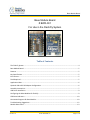
Base Module Board
# BWR-001
For Use in the FlashFly System
Table of Contents
The FlashFly System ...................................................................................................................................... 4
Base Module Board ....................................................................................................................................... 5
Features ........................................................................................................................................................ 5
Key Specifications ......................................................................................................................................... 5
Kit Contents................................................................................................................................................... 5
Tools Required .............................................................................................................................................. 5
Application Ideas........................................................................................................................................... 6
Optional USB to RS-232 Adapter Configuration ........................................................................................... 6
Assembly Instructions ................................................................................................................................... 7
USB Driver Installation .................................................................................................................................. 9
Configuring the XBee Modules for FlashFly .................................................................................................. 9
LED Status Indicators .................................................................................................................................. 10
Connection Diagrams for Base Module ...................................................................................................... 10
Troubleshooting Suggestions ...................................................................................................................... 12
Module Dimensions .................................................................................................................................... 13
Version 1.0
© 2011 Blue Wolf, Inc.
Page 3 of 13
Base Module Board
Engineering » Design » Product
The FlashFly System
FlashFly is an innovative system that allows a user to remotely download BASIC Stamp
programs to Parallax’s Stamp modules or interpreter chips. FlashFly’s wireless capabilities, in
coordination with common Series 1 XBee modules, will allow a user with a BASIC Stamp mobile
robot or stationary platform to modify his or her program remotely.
Therefore, individuals who have mobile robots, sprinkler systems, weather stations, alarm
systems, or any other remote or fixed controller board with a BASIC Stamp core will benefit from
the FlashFly system because wirelessly downloading a program change is now achievable and
easy.
FlashFly eliminates the tedious task of having to connect a robot or a fixed platform to a
computer before any programming changes can be made. FlashFly also enriches a user’s
learning experience by providing instant feedback data to the DEBUG terminal screen, which
allows a user to evaluate his or her program flow and I/O data wirelessly. FlashFly can also be
used in conjunction with any other microprocessor platform that needs to transmit data
wirelessly.
The two main components of the FlashFly system are the Base Module and the Remote
Module. These two modules are responsible for communicating back and forth. In the FlashFly
system, there are three options for the Remote Module component. Each of these options will
allow for wireless downloading of BASIC Stamp programs.
1. The Remote Module can be inserted into a breadboard or user-defined board for direct
communication with a BASIC Stamp interpreter chip.
2. The RS-232 serial adapter board can be used in the FlashFly system to connect to a
mobile or fixed platform when the user has a serial BASIC Stamp version (a board that
uses a DB-9 connecter).
3. The USB Stamp adapter module can be used in the FlashFly system to connect to the
Remote Module when the user has a USB-type board with BASIC Stamp.
The following list identifies each of the FlashFly system components, their respective product
numbers, and their role in FlashFly. The last two boards are interchangeable, depending on the
BASIC Stamp version a user has.
Base Transmitter Board (BWR-001) – This board connects to the computer.
Remote Receiver Board (BWR-002) – This board connects to a mobile or fixed robot.
RS-232 Adapter Board (BWR-003) – This board connects to the remote board.
USB Stamp Adapter Board (BWR-004) – This board connects to the remote board.
Version 1.0
© 2011 Blue Wolf, Inc.
Page 4 of 13
Base Module Board
Engineering » Design » Product
Base Module Board
The Base module is one of the components necessary to wirelessly download BASIC Stamp
programs. The Base module comes in a partially assembled kit. This cost-effective solution is
an easy way to interface the FlashFly system to a PC using a USB connection. Additionally, the
Base module also serves as an experimentation board for the XBee modules. By using the
additional connection points, one can connect pluggable wires, solder connections, or install
0.100” headers (not supplied) for breadboarding to the additional circuitry available on the XBee
modules.
An additional benefit of the Base module, when paired to the RS-232 adapter module, is that it
can also serve as an extra USB to COMM serial port adapter. NOTE: A USB A to mini B cable
is required for use, but it is not supplied.
Features
Provides an easy interface for communicating with the FlashFly system
Four status indicator LEDs for Power, RSSI, RX, and TX
Converts XBee 2mm pin spacing to 0.100” pin spacing
Provides easy pluggable wire or solder connections for XBee I/O
When used with an RS-232 adapter board, this will function as an extra USB to
RS-232 COMM port adapter (TX,RX,DTR)
Partially assembled kit for flexible configuration
Works with the FlashFly Remote module
Can work as a transceiver for communication with other XBee systems
Will support XBee or XBee Pro Modules (Series 1 is required for the FlashFly
system)
Key Specifications
Power requirements: comes from the computer USB port
On board 3.3V regulator for XBee Module
Operating temperature: -40 to +185F (-40 to 85 C)
Dimensions: 1.13” wide by 1.83” long (with header)
Kit Contents
BWR-001 PCB (1) — SMD components are pre-soldered
10-pin 2.0mm sockets (2) — Solder to top of board
8-pin right angle 0.100” header (1) — Solder to bottom of board, if desired
Tools Required
Version 1.0
Soldering iron (always wear safety glasses when soldering)
Solder (some soldering experience required)
Flux
© 2011 Blue Wolf, Inc.
Page 5 of 13
Base Module Board
Engineering » Design » Product
Application Ideas
Can easily configure XBee or XBee Pro Modules using a PC
Easy connection for mounting XBee modules to breadboard or proto boards
Can be used as a transceiver for any microcontroller using a TX and RX line
Can remotely monitor fixed or mobile devices (such as remote weather stations,
mobile robots, alarm system, production operations, and so on)
Optional USB to RS-232 Adapter Configuration
The Base module board has the option to solder an 8-position right-angle header on the board.
This header is intended for use with the RS-232 adapter board so one can program directly with
a USB port, if desired. Effectively, this optional enhancement allows for an extra USB to RS-232
port. To utilize this optional feature, which adds an additional USB to RS-232 converter:
1. Remove the XBee module from the Base transmitter board.
2. Plug the Base transmitter board into the RS-232 board.
3. Plug one end of the USB cable into the Base transmitter board and the other end into
the USB port on the computer.
Version 1.0
© 2011 Blue Wolf, Inc.
Page 6 of 13
Base Module Board
Engineering » Design » Product
Assembly Instructions
HINT: When soldering headers or pins, solder one and align the connector so it is perpendicular
to the board. If needed, reheat the first soldered pin to realign. Once the connector is straight
and perpendicular, securely solder the remaining headers or pins.
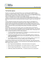
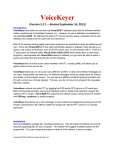
Step 1:
Verify the kit contains the following parts, as
shown in the photograph to the right.
Version 1.0
© 2011 Blue Wolf, Inc.
Page 7 of 13
Base Module Board
Engineering » Design » Product
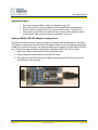
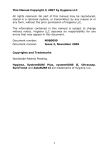
Step 2:
Install both (2) 10 position 2.0mm sockets into
the TOP of the board. Once installed, solder
them in place from the BOTTOM of the board.
Step 3:
Optional, install the 8 pin right angle 0.100”
male header on the BOTTOM of the board.
Once installed, solder it in place from the TOP
of the board.
Step 4:
The unit (along with the XBee module) is
complete.
Version 1.0
© 2011 Blue Wolf, Inc.
Page 8 of 13
Base Module Board
Engineering » Design » Product
USB Driver Installation
A USB A to Mini B cable is needed to connect the Base module to the PC, which is sold
separately on Blue Wolf’s website. The appropriate drivers for the FTDI VCP chip are also
necessary, which can be downloaded from the FTDI website
(http://www.ftdichip.com/Drivers/VCP.htm).
It is possible that the FTDI USB drivers are already installed, since this is a common chip used
in the market. If any problems arise with these drivers, there is a lot of information on the
internet that explains how to install and/or troubleshoot the drivers.
Depending upon which option was selected, when purchasing the FlashFly system, each XBee
module (Base and Remote) will have to be configured using the X-CTU software from Digi (see
the links on the FlashFly product page for the latest locations and files). If a completely
programmed XBee kit was purchased, configuring the modules is not necessary.
CAUTION
As long at the USB port is providing power, the Base module is powered up.
Also, the I/O signal lines on the XBee module are at a 3.3V level and should
not be connected directly to a 5V system without proper signal buffering. The
XBee I/O lines are not 5V tolerant, so damage may occur.
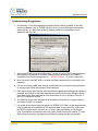
Configuring the XBee Modules for FlashFly
If the XBee modules need to be configured for FlashFly, visit Blue Wolf’s website
(www.bluewolfinc.com) for the latest XBee configuration profiles. From the homepage, navigate
to the Products section of the website. Under the FlashFly product description, there is a
FlashFly Downloads link where the latest profiles can be downloaded and saved locally to a PC.
The .zip file contains the configuration files needed for FlashFly to work properly. There are two
files in the .zip package: one for the Base module and one for the Remote module. Using the XCTU configuration software and the Base module for programming, load the respective profiles
onto each respective XBee module (be sure to mark them accordingly).
NOTE: Preconfigured XBee modules can be purchased through the Blue Wolf website.
Version 1.0
© 2011 Blue Wolf, Inc.
Page 9 of 13
Base Module Board
Engineering » Design » Product
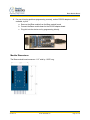
LED Status Indicators
The Base module board has four LED’s for status indication. If the board is connected to a USB
cable, the Red PWR LED is illuminated. If data is being transmitted, the TX Red LED is
illuminated. Conversely, if data is being received, the GRN RX LED will be illuminated. The
Green RSSI LED will illuminate if the signal strength is strong enough from the Remote module.
The following list identifies the LED functions.
Red – Power On
Green – RSSI
Red – Transmit (TX) data is being sent from the computer.
Green – Receive (RX) data is being received from the remote device.
Connection Diagrams for Base Module
The Base module board is primarily made for use with the FlashFly system to wirelessly
download programs. However, the board also allows for additional experimentation with other
XBee I/O modules using soldered wires or 0.100” male headers.
WARNING
Experimenting with other XBee I/O modules will disable the use of the FlashFly
in-system downloading capabilities if you need to use DI04 or DI05.
In order to experiment with other XBee I/O modules, some of the solder pad jumpers (on the
back side of the board) will have to be modified if use of the DIO4 or DIO5 individual I/O lines is
Version 1.0
© 2011 Blue Wolf, Inc.
Page 10 of 13
Base Module Board
Engineering » Design » Product
needed. DIO4 and DIO5 are tied to DTR and RTS respectively, so cutting these solder traces
breaks the connection from DIO4 to DTR and from DIO5 to RTS.
Using an X-ACTO™ knife, cut the trace on SP2 from the middle pad to the pad on the bottom
side. Next, cut the trace on SP3. At this point, the FlashFly module can no longer be used for
wireless downloading unless jumper wires are soldered back in place on the SP2 and SP3
solder pads.
NOTE: SP1 is reserved for those who are experimenting with their own non-BASIC Stamp
microcontroller. In this case, pin 6 of the RS-232 adapter board connects to SP1, which in turn
can be connected to any XBee I/O.
Version 1.0
© 2011 Blue Wolf, Inc.
Page 11 of 13
Base Module Board
Engineering » Design » Product
Troubleshooting Suggestions
1. Occasionally, on the first programming attempt after the editor is started, a user may
receive a hardware error or STAMP not found error (incorrect DIP switch settings can
cause this too). If a user does an identify Stamp, make sure a COMM port is not
disabled in the Port List.
2. When writing BASIC programs in the Editor, it is best to have a Port Directive defined in
the program. For example, if the BASE module board is showing up as COMM 19,
complete a Port Directive assignment of ' {$PORT COM19} to ensure connectivity.
3. Also, ensure the red PWR LED is on when the Base module board is connected to the
computer.
4. If a user is running a USB cable through a USB expansion port and is having problems,
try connecting the USB cable directly to the computer.
5. Running more than one FlashFly system has been tested and everything works properly.
However, the PAN ID on the XBee modules should NOT be the same between the two
sets. Refer to the XBee manuals for more information on how to configure Pan ID’s in
the X-CTU software from Digi.
6. The FlashFly system was designed for (and tested on) both Series 1 regular modules
and Series 1 XBee Pro modules.
7. If a remote device has a significant amount of SERIAL OUT data in a tight programming
loop (for example, an immediate GOTO statement back to the output line), make sure
the BASIC program has a minimum of a 25 msec. delay somewhere in the program
loop. This ensures the transmit module can communicate with the RX module. If a user
does not have this delay, programming the Remote module may be unsuccessful.
Version 1.0
© 2011 Blue Wolf, Inc.
Page 12 of 13
Base Module Board
Engineering » Design » Product
8. If a user is having problems programming remotely, and an RS-232 adapter module is
available, try this:
a. Remove the XBee module from the Base module board.
b. Connect the Base module board to the RS-232 adapter board.
c. Plug this into the device and try programming directly.
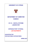
Module Dimensions
The Base module board measures 1.13” wide by 1.835” long.
Version 1.0
© 2011 Blue Wolf, Inc.
Page 13 of 13