1
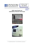
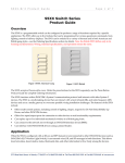
Installer manual
3
General instructions
1 Installer manual
1.1 General instructions
This manual aims at providing information to install the CRS receiving
unit of Autec Dynamic series radio remote controls.
Instructions regarding the use of the radio remote control are contained
in the “user manual” (provided together with the radio remote control).
This manual and the “user manual” must be read and understood in all
their parts by those who decide and/or carry out the radio remote control
installation.
Always remember that:
CRS receiving unit
- photos and drawings contained in this manual are useful examples
that help understand its instructions and warnings
- if necessary, contact Autec if any of the instructions and/or warnings given in this manual are not clear.
No part of this manual may be reproduced, in any form or by any means, without written permission of Autec (including recording and photocopying).
If this manual is lost or damaged, ask Autec for a copy. Please specify the serial number of the related radio remote
control.
All installation operations can only be carried out by qualified technicians who are suitably trained with respect to
the relevant norms and laws.
This manual integrates instructions provided by the manufacturer of the machine where the radio remote control is
to be installed.
As for instructions and warnings regarding the machine where the radio remote control is to be installed, follow the
instructions given in the machine's manual.
1.2 Symbol conventions
Three symbols are employed in this manual, which are used to highlight specific safety-related issues. They are
classified according to the hazardous situation that may arise and on the possible consequences:
If the highlighted instructions are not respected ...
Symbol
... a dangerous situation
will occur …
... consequences for people
may be …
... consequences for property
may be …
… very likely.
… critical
(death or physical damage).
… critical.
… probably.
… critical
(death or physical damage).
… critical.
… probably.
… moderate
(non-severe physical damage).
… moderate.
This symbol is also used, and it identifies texts to be read carefully.
Index
Back
LIICRS00E0-01.fm
AUTEC - Dynamic Series
Installer manual
4
CRS receiving unit
Description
2 CRS receiving unit
2.1 Description
The receiving unit uses the CANopen® communication protocol to communicate in a CAN bus network. The receiving unit acts as a slave node within this network.
STOP and SAFETY commands are sent via CAN network and also activate their corresponding outputs.
It is not possible to only rely on the CAN communication status to maintain or bring the remote controlled
machine to a safe condition. Messages sent by the radio remote control via CAN network do not in fact ensure the same safety features as the corresponding commands that are directly carried out by the receiving
unit's safety outputs. Please refer to chapters 7 and 6 for instructions to correctly wire such outputs.
A
B
E
D
A
141 mm (5.55 In)
B
74 mm (2.91 In)
C
plug
D
pins on the plug
E
BNC connector for antenna
C
Receiving unit's pins are identified through their corresponding cavities on the connector (see paragraph 4.2.1).
2.2 Technical data
Power supply ..................................................................................................................................................................... 8-30 V
Absorbed power ........................................................................................................................................................................ 3 W
Antenna............................................................................................................................................................................ dedicated
Outputs' maximum switching voltage ................................................................................................................................... 30 V
Rated current of outputs STP_1 and STP_2 with electronic protection (restorable) ................................................................. 8 A
Protection of STP_1 and STP_2 (fail safe) ............................................................................................................................. 15 A
Rated current of SAF_1 with electronic protection (restorable) ................................................................................................ 8 A
Protection of SAF_1 (fail safe) ................................................................................................................................................ 15 A
Rated current of SAF_2 ............................................................................................................................................................ 2 A
Protection of SAF_2 (restorable) .................................................................................................................................... 4 A (25°C)
Housing material .......................................................................................................................... PBT (30% fg) and PA6 (30% fg)
Protection degree...................................................................................................................................................................... IP65
Dimensions ........................................................................................................................ 153 x 148 x 55 mm (6.1 x 5.9 x 2.2 In)
Weight ..................................................................................................................................................................... 0.5 kg (1.1 Lb)
Index
Back
AUTEC - Dynamic Series
Installer manual
LIICRS00E0-01.fm
Light signals
5
POWER LED (green)
3 Light signals
The CRS receiving unit has four LEDs:
- POWER is green
- ALARM is red
- RUN is green
- ERR is red
3.1 POWER LED (green)
The POWER LED indicates the status of the receiving unit and of the radio link.
The POWER LED ...
... is off
Meaning
The receiving unit is switched off.
... blinks slowly
Radio link has been built.
... is on
No radio link.
3.2 ALARM LED (red)
The ALARM LED warns about anomalies in the receiving unit.
The ALARM LED ...
... is off
Meaning
The receiving unit works correctly.
... repeats the sequence: a slow blink and a pause
Error on the STOP outputs.
... repeats the sequence: two slow blinks and a pause
Error on the SAFETY outputs.
... is on
The receiving unit does not work correctly.
3.3 RUN LED (green)
RUN LED signals reflect the guidelines of the CANopen® standard, CiA recommendation 303-3. Terms used in the
following table are therefore consistent with such recommendation.
The RUN LED indicates the status of the application layer (CANopen node).
The RUN LED ...
... is off
Meaning
The CAN node is off:
the receiving unit is switched off or is performing a reset
... blinks fast
The CAN node does not send commands on the network:
configuration through the LSS services is in progress
... blinks slowly
The CAN node does not send commands on the network:
the receiving unit is in state PREOPERATIONAL
Index
Back
LIICRS00E0-01.fm
AUTEC - Dynamic Series
Installer manual
6
Light signals
ERR LED (red)
The RUN LED ...
Meaning
... repeats the sequence: a slow blink and a pause
The CAN node does not send commands on the network:
the receiving unit is in state STOPPED
... is on
The CAN node is working correctly:
the receiving unit is in state OPERATIONAL
3.4 ERR LED (red)
ERR LED signals reflect the guidelines of the CANopen® standard, CiA recommendation 303-3. Terms used in the
following table are therefore consistent with such recommendation.
The ERR LED indicates the status of the (CAN bus) physical layer and errors due to wrong configurations.
The ERR LED ...
... is off
Meaning
No operating problems.
... blinks fast
CAN communication is not available:
configuration through the LSS services is in progress
... blinks slowly
CAN communication does not work correctly:
configuration errors on the receiving unit.
... repeats the sequence: a slow blink and a pause
CAN communication does not work correctly:
at least one of the frame error counters has reached the
warning level.
... repeats the sequence: two slow blinks and a pause
CAN communication does not work correctly:
a "heartbeat event" or a "guard event" has occurred.
... repeats the sequence: three slow blinks and a pause
... is on
CAN communication does not work:
the SYNC message has not been received within the configured communication cycle period time out.
CAN communication does not work:
the CAN controller is bus off.
Index
Back
AUTEC - Dynamic Series
Installer manual
LIICRS00E0-01.fm
Electrical connection
7
Crimp
4 Electrical connection
Connector indicated in paragraph 4.2.1 and the related terminals are used for the connection with the machine:
1. crimp wires (see paragraph 4.1)
2. insert terminated wires in the connectors (see paragraph 4.2)
3. insert the connector in the receiving unit's plug and screw it in with the screw (1/4 IN).
The connector has 30 cavities; each of them can only admit a single terminal, and a single wire can be crimped to
each terminal.
4.1 Crimp
Use terminals CINCH 425-00-00-873 and the hand crimp tool CINCH 599-11-11-616 to crimp the wires.
Do not use wires with sections smaller than what provided in the following indications.
Power supply
SAFETY
STOP
Cable control
CAN BUS
0.5
1
1
0.5
0.5
Minimum section
[sq. mm]
Instructions to crimp the wires
1
Grip the hand crimp tool securely and squeeze, ratcheting the mechanism until it bottoms out.
Then allow it to open completely.
2
With hand tool in ready position, (open handle) open the terminal receptacle.
Terminal receptacle
3
Insert a single terminal in the middle hole of the terminal receptacle.
Index
Back
LIICRS00E0-01.fm
AUTEC - Dynamic Series
Installer manual
8
Electrical connection
Crimp
Instructions to crimp the wires
4
Close the terminal receptacle with the terminal in it.
5
Pre-strip wire as shown in the drawing.
6
Insert the pre-stripped wire into the terminal located in the hand crimp tool.
With the terminal and wire set in the proper position, hold the wire stationary and
squeeze the tool together.
Complete the crimp by squeezing the tool until the ratchet releases.
Remove the terminated wire from the tool.
7
A properly terminated wire would look similar to the drawing. The arrow shows the
approximate point where the end of the insulation should be placed.
Index
Back
AUTEC - Dynamic Series
Installer manual
LIICRS00E0-01.fm
Electrical connection
9
Connection
4.2 Connection
4.2.1 Connector
Use connector CINCH 581-01-30-029 to connect the terminated wires to the plugs on the receiving unit.
Fastening screw
A
B
C
D
E
1
/
CAN_SHLD
CAN_H
A485_CBL
/
2
/
CAN_GND
CAN_L
B485_CBL
PWR+_CBL
3
/
CAN_T
ENA_CBL
GND_CBL
PWR-_CBL
F
G
H
J
K
SAF_1_IN
STP_2_OUT
STP_2_IN
STP_1_OUT
STP_1_IN
1
SAF_1_OUT
PWR-
PWR+
PWR-
SAF_2_OUT
2
STP_C
PWR-
PWR+
PWR-
SAF_2_D
3
Name
Cavity/pin
Description
/
A-1
reserved
/
A-2
reserved
/
A-3
reserved
CAN_SHLD
B-1
shield
CAN_GND
B-2
GND
CAN_T
B-3
line termination (120 Ω)
CAN_H
C-1
H
CAN_L
C-2
L
ENA_CBL
C-3
presence of cable control
A485_CBL
D-1
A
B485_CBL
D-2
B
GND_CBL
D-3
GND
/
E-1
not connected
PWR+_CBL
E-2
transmitting unit's power supply
positive terminal
PWR-_CBL
E-3
transmitting unit's power supply
negative terminal
PWR-
G-2, G-3, J-2, J-3
negative
PWR+
H-2, H-3
positive
SAF_1_IN
F-1
power supply positive terminal of
SAF_1
SAF_1_OUT
F-2
output of SAF_1
SAF_2_OUT
K-2
output of SAF_2
SAF_2_D
K-3
reverse recovery diode
STP_1_IN
K-1
power supply positive terminal of
STP_1
STP_1_OUT
J-1
output of STP_1
STP_2_IN
H-1
power supply positive terminal of
STP_2
STP_2_OUT
G-1
output of STP_2
STP_C
F-3
smoothing capacitor
Function
/
CAN BUS
(see paragraph 9)
Cable control
(see paragraph 10)
Power supply
(see paragraph 8)
SAFETY
(see paragraph 7)
STOP
(see paragraph 6)
Index
Back
LIICRS00E0-01.fm
AUTEC - Dynamic Series
Installer manual
10
Electrical connection
Connection
A-1
PWR+
H-2
H-3
PWR-
G-2
G-3
J-2
J-3
A-2
A-3
B-1 CAN_SHLD
C-1
CAN_T
CAN_H
K-1
OUT
J-1
STP_C
F-3
IN
H-1
OUT
G-1
IN
F-1
STP_1
B-2 CAN_GND
B-3
IN
120Ω
CAN BUS
+
1000μF
C-2 CAN_L
STP_2
C-3 CBL_ENA
D-1 CBL_A485
SAF_1
D-2 CBL_B485
D-3 CBL_GND
OUT
CABLE
E-1
F-2
OUT
K-2
D
K-3
SAF_2
E-2 CBL_PWR+
E-3 CBL_PWR-
4.2.2 Inserting terminals in the connector
Instructions to wire the connector
1
Before wiring, make sure that the secondary locks are in the pre-stage/open position,
as shown in the picture.4.2.3
Secondary lock
2
Grasp connector with cavity letter and number identification in the upright position.
Index
Back
AUTEC - Dynamic Series
Installer manual
LIICRS00E0-01.fm
Electrical connection
11
Connection
Instructions to wire the connector
3
Insert the terminated wire in the corresponding cavity.
4
Complete terminal insertion by pushing the terminated wire through the cavity until
you hear a "click". Verify proper terminal seating with a light tug on the wire.
Repeat step 3 until all wires are inserted.
Use seal plugs in unused cavities.
5
Completely insert the secondary locks.
If a resistance is felt while closing the secondary lock, do not force to close.
Index
Back
LIICRS00E0-01.fm
AUTEC - Dynamic Series
Installer manual
12
Electrical connection
Connection
4.2.3 Removing terminals from the connector
To remove the terminals from the connector, do the following:
- use the tweezers tool CINCH 599-11-11-628 to remove the secondary lock
- use the terminal removal tool CINCH 581-01-18-920 to remove the terminals.
Removing the secondary lock
1
Position the connector so that secondary lock locking tabs are in an upright position.
2
Insert the tweezers tool besides the secondary lock locking tabs.
3
Push tweezers in and squeeze to remove the secondary lock out of the connector.
Terminal removal
1
Cavities
Grasp connector with cavity letter and number identification in the upright position.
Terminal removal tool is to be inserted in the front of the cavity, opposite to the wires.
Removal tool
2
Locate wire to be extracted and its cavity in the front of the connector.
Index
Back
AUTEC - Dynamic Series
Installer manual
LIICRS00E0-01.fm
Electrical connection
13
Connection
Terminal removal
3
Insert the removal tool straight in, as show in the picture.
4
Push the removal tool straight in so it bottoms against the connector.
Make sure that the wire is inserted safely by pulling it for approx. 2mm without forcing.
Remove the tool from the cavity.
Pull the wire out.
Index
Back
LIICRS00E0-01.fm
AUTEC - Dynamic Series
Installer manual
14
Warnings for installation
General
5 Warnings for installation
The radio remote control can only be installed and tested by competent staff that masters the technical knowledge
required to carry out such procedure and is qualified according to the regulation of the country where the radio remote control is mounted.
Only if the radio remote control is installed correctly can it be used safely.
Besides instructions established by the machine's manufacturers, installers must always observe the following
warnings.
Never connect power supply positive pole to the outputs' pins. Such connection would exclude the UMFS
and STOP safety functions. In this case the machine may be in a dangerous condition, out of the user's
control.
The installer or the machine's manufacturer must avoid that a power supply positive pole is connected to
outputs' pins.
5.1 General
Respect and enforce the provisions of all reference standards relevant in the concerned application field
(i.e. IEC 60204-32 for hoisting machines.)
Always follow the instructions provided in the “technical data sheet” and respect values given in the technical data to carry out correct installation.
Due to the characteristics of radio propagation (i.e.: EM interference, near out-of-range condition), a delay
up to the "Passive stop time" may occasionally occur from the moment a command in the transmitting unit
is released to the moment its corresponding output in the receiving unit is deactivated.
With regards to the SAFETY outputs only (SAF_1 and SAF_2), a regular deactivation delay (approx. 1 second) applied to such outputs may add to this time.
Those who decide upon the installation of the radio remote control must make sure that these delays never
lead to a dangerous situation in the specific uses.
5.2 Mounting and fastening the receiving unit in the best position
Place the receiving unit so that it can be easily reached in case of need.
Place the receiving unit so that it can be easily reached, and far from heat sources (i.e. exhaust pipes, heat
exchangers, radiators).
Place the receiving unit vertically, with the plug facing down.
The receiving unit's back should be placed against a metal surface, to improve heat sink effect.
Fix the receiving unit in four points, using the specific holes in the housing.
Do not perforate the receiving unit in any case.
If the unit is installed on machines that produce heavy vibrations, it is recommended to mount it on a metal
plate and to fasten the metal plate to the machine with vibration dampers.
5.3 Mounting and fastening the antenna in the best position
Install the antenna so that shields, structures or materials do not obstruct the radio link; in particular:
- the antenna shall not be placed inside closed metal containers
- the antenna must be installed in a vertical position, and possibly in sight of the work area
- the antenna must be placed at least 50 cm far from metal objects in its surroundings.
If these warnings are disregarded, the typical working range of the radio remote control may be reduced.
Place the antenna as far as possible from the receiving unit and from other electrical and electronic devices.
Index
Back
AUTEC - Dynamic Series
Installer manual
LIICRS00E0-01.fm
Warnings for installation
15
Wiring
5.4 Wiring
Respect instructions provided in chapter 4 to connect the receiving unit with the machine.
Make sure that the receiving unit's power supply is protected against short circuits and is supplied either
by a battery or by a power supply unit with safety isolating transformer.
The power supply of the receiving unit must have a switch that allows power supply disconnection during
installation, wiring and/or maintenance operations. Connect the receiving unit immediately downstream of
the machine main switch or of the electrical panel main switch (see chapter 8).
Pay special attention to the currents flowing in outputs SAF_1, SAF_2, STP_1 and STP_2: they shall not
exceed the maximum permitted values (see paragraph 2.2).
The current of STOP outputs is interrupted at regular intervals for approx. 1 ms every 100 ms. If STOP outputs are used to power electronic devices, check that they are compatible with this recurring interruption
(use suitable filters if necessary).
Fasten the wiring cables of the CRS receiving unit so as not to apply burdens on the wiring connectors.
5.5 At end of installation
Make sure that during installation the safety mechanisms on the radio remote control and/or in the machine
have not been made ineffective by possible procedures carried out.
5.6 Testing
After installation and wiring, test the system “machine+radio remote control”, and check that the operations carried out correspond exactly to the commands sent (in particular check the STOP command).
The installer must check and complete the "Technical Data Sheet" in all its parts, adding the date the system has
been put into service, his stamp and signature.
Make sure that outputs SAF_1 and SAF_2 only activate after the radio remote control start up.
In case of malfunction, disable the system “machine+radio remote control” until the problem has been
completely solved.
Index
Back
LIICRS00E0-01.fm
AUTEC - Dynamic Series
Installer manual
16
STOP outputs
Stop function complying with cat. 4 PL=e and SIL 3
6 STOP outputs
Outputs STP_1 and STP_2 are enabled by the STOP command.
Pins K-1 (STP_1_IN) and H-1 (STP_2_IN) shall always receive power supply between 8 and 30 V , even though
the corresponding outputs STP_1 and STP_2 are not used.
The current of STOP outputs is interrupted at regular intervals for approx. 1 ms every 100 ms. Risk analysis
must consider this interruption.
Wiring of outputs STP_1 and STP_2 is the factor that defines the safety level for the UMFS protection function.
6.1 Stop function complying with cat. 4 PL=e and SIL 3
The stop function complies with cat. 4 and PL=e according to the EN ISO 13849-1 and with SIL 3 according to the
EN IEC 62061 if outputs STP_1 and STP_2 in the receiving unit have been wired as follows:
IN
K-1
OUT
J-1
IN
H-1
OUT
G-1
a, b: redundant devices that
bring the machine to a safe
state (i.e. contactors, safety
PLCs)
STP_1
STP_2
+
PWR-
G-2
G-3
J-2
J-3
a
b
-
The installer or the machine manufacturer is in any case responsible for carrying out wiring in such a way
as to ensure the safety level required by risk analysis; in particular, short circuit among the wires of the
STOP circuit outside the receiving unit must be avoided.
Index
Back
AUTEC - Dynamic Series
Installer manual
LIICRS00E0-01.fm
STOP outputs
17
Stop function complying with cat. 3 PL=d and SIL 2
6.2 Stop function complying with cat. 3 PL=d and SIL 2
If outputs STP_1 and STP_2 require a 2-wire wiring, the stop function complies with cat. 3 and PL=d according to
the EN ISO 13849-1 and SIL 2 according to the EN IEC 62061 if wiring is carried out as follows:
IN
K-1
OUT
J-1
STP_C
F-3
IN
H-1
OUT
G-1
a: device that brings the
machine to a safe
state (i.e. contactor,
safety PLC)
STP_1
+
1000μF
STP_2
+
PWR-
G-2
G-3
J-2
J-3
a
-
When outputs STP_1 and STP_2 are connected in series, wire cavity STP_C as shown in the figure, so that
the filter capacitor is connected.
If failure not related to the CRS receiving unit occurs (i.e. short circuit between STP_2_IN and STP_2_OUT),
the filter capacitor (1000 μF) may cause a further delay in de-energising the STOP circuit, thus extending
the declared stop time. This delay depends on device “a” (i.e. new delay is shorter than 500 ms if impedance of device “a” is lower than 500 Ω or if such device absorbs constant current higher than 50 mA). Take
into account this aspect when doing the risk analysis, as well as the fact that such failure is not detected
by the radio remote control.
The installer or the machine manufacturer is in any case responsible for carrying out wiring in such a way
as to ensure the safety level required by risk analysis; in particular, short circuit among the wires of the
STOP circuit outside the receiving unit must be avoided.
Index
Back
LIICRS00E0-01.fm
AUTEC - Dynamic Series
Installer manual
18
SAFETY outputs
UMFS function complying with cat. 3 PL=d and SIL 2
7 SAFETY outputs
Outputs SAF_1 and SAF_2 are enabled by the SAFETY command.
Outputs SAF_1 and SAF_2 are designed to drive power loads and are protected through overvoltage suppressors
and reverse recovery diodes, to ensure longest lifetime in most applications.
If these outputs drive inductive loads (i.e. solenoid valves, relays), it is recommended to use a reverse recovery
diode with the load, to further reduce the effects of demagnetisation currents.
Pin F-1 (SAF_1_IN) shall always receive power supply between 8 and 30 V , even though output SAF_1 is not
used.
When failure is detected on outputs SAF_1 and SAF_2, the STOP circuit automatically opens within 200 ms.
Risk analysis must consider this delay.
Wiring of outputs SAF_1 and SAF_2 is the factor that defines the safety level for the UMFS protection function.
7.1 UMFS function complying with cat. 3 PL=d and SIL 2
The UMFS safety function meets the requirements of cat. 3 and PL=d according to the EN ISO 13849-1 and of
SIL 2 according to the EN IEC 62061 only if SAFETY outputs enable the device that releases pressure from the
machine's hydraulic circuit. Wiring shall be as follows:
CRS
IN
a: device releasing pressure from the hydraulic circuit (i.e. solenoid valve).
F-1
SAF_1
OUT
D
OUT
F-2
K-3
+
a
-
Only use SAF_2_OUT as indicated in
the wiring diagram on the side.
K-2
SAF_2
PWR-
G-2
G-3
J-2
J-3
The installer or the machine manufacturer is in any case responsible for carrying out wiring in such a way
as to ensure the safety level required according to the risk analysis.
Index
Back
AUTEC - Dynamic Series
Installer manual
LIICRS00E0-01.fm
Power supply
19
Wiring power supply
8 Power supply
Power on the receiving unit through a battery or a power supply unit with safety isolating transformer, and always
respect technical data.
Power supply must be protected against short circuits.
The power supply must have a switch that allows power supply disconnection during installation, wiring and/or
maintenance operations. Connect the receiving unit immediately downstream of the machine main switch or of the
electrical panel main switch.
8.1 Wiring power supply
Connect power supply to the receiving unit as follows:
CRS
PWR+
H-2
H-3
PWR-
G-2
G-3
J-2
J-3
+
-
Index
Back
LIICRS00E0-01.fm
AUTEC - Dynamic Series
Installer manual
20
CAN BUS
Wiring the CAN network
9 CAN BUS
The CAN BUS port is used to connect the receiving unit in a network that communicates through CANopen® protocol.
9.1 Wiring the CAN network
Use CAN_H and CAN_L to wire the CAN network.
Use CAN_GND to wire GND of CAN network.
A coiled and shielded cable should be used. In this case, use CAN_SHLD to wire the shield.
CRS
B-1 CAN_SHLD
B-2 CAN_GND
B-3
CAN_T
C-1
CAN_H
120Ω
CAN BUS
C-2 CAN_L
Both ends of CAN networks must be terminated with a 120 Ω resistor between CAN_H and CAN_L.
Node 1
Node 2
Node n
CAN_H
120 Ω
120 Ω
CAN_L
CAN_GND
If the CRS receiving unit is at the beginning or at the end of the network, connect outputs CAN_T and CAN_L so
that the line termination is connected.
CRS
B-1 CAN_SHLD
B-2 CAN_GND
B-3
C-1
CAN_T
CAN_H
120Ω
CAN BUS
C-2 CAN_L
All CAN network nodes must have the same bit rate. The bit rate defines the maximum length for the network:
Bitrate
[kbit/s]
1000
800
500
250
125
100
50
20
10
Approximate network length
[m]
30
50
100
250
500
600
1000
2500
5000
Index
Back
AUTEC - Dynamic Series
Installer manual
LIICRS00E0-01.fm
Cable control
21
Wiring the cable control's connector
10 Cable control
The cable control is used to connect the transmitting unit to the receiving unit through a cable, that replaces the
radio link. To connect the cable, the corresponding connectors on the transmitting unit and on the machine must
be present.
Connector for cable control
Transmitting unit
Machine
Cable control
10.1 Wiring the cable control's connector
Install the provided connector on the machine and connect it to the CRS unit as shown below.
Connector for cable control on
the machine
5
4
6
8
3
2
7
1
7
2
3
8
5
6
1
4
Pale blue
Brown
Green
Red
CRS
C-3 ENA_CBL
D-1 A485_CBL
D-2 B485_CBL
D-3 GND_CBL
CABLE
E-1
Grey
Pink
E-2 PWR+_CBL
E-3 PWR-_CBL
Index
Back
LIICRS00E0-01.fm
AUTEC - Dynamic Series
Installer manual