1
4
CRS receiving unit
Description
2 CRS receiving unit
2.1 Description
The receiving unit uses the CANopen® communication protocol to communicate in a CAN bus network. The receiving unit acts as a slave node within this network.
STOP and SAFETY commands are sent via CAN network and also activate their corresponding outputs.
It is not possible to only rely on the CAN communication status to maintain or bring the remote controlled
machine to a safe condition. Messages sent by the radio remote control via CAN network do not in fact ensure the same safety features as the corresponding commands that are directly carried out by the receiving
unit's safety outputs. Please refer to chapters 7 and 6 for instructions to correctly wire such outputs.
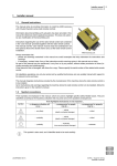
A
B
E
D
A
141 mm (5.55 In)
B
74 mm (2.91 In)
C
plug
D
pins on the plug
E
BNC connector for antenna
C
Receiving unit's pins are identified through their corresponding cavities on the connector (see paragraph 4.2.1).
2.2 Technical data
Power supply ..................................................................................................................................................................... 8-30 V
Absorbed power ........................................................................................................................................................................ 3 W
Antenna............................................................................................................................................................................ dedicated
Outputs' maximum switching voltage ................................................................................................................................... 30 V
Rated current of outputs STP_1 and STP_2 with electronic protection (restorable) ................................................................. 8 A
Protection of STP_1 and STP_2 (fail safe) ............................................................................................................................. 15 A
Rated current of SAF_1 with electronic protection (restorable) ................................................................................................ 8 A
Protection of SAF_1 (fail safe) ................................................................................................................................................ 15 A
Rated current of SAF_2 ............................................................................................................................................................ 2 A
Protection of SAF_2 (restorable) .................................................................................................................................... 4 A (25°C)
Housing material .......................................................................................................................... PBT (30% fg) and PA6 (30% fg)
Protection degree...................................................................................................................................................................... IP65
Dimensions ........................................................................................................................ 153 x 148 x 55 mm (6.1 x 5.9 x 2.2 In)
Weight ..................................................................................................................................................................... 0.5 kg (1.1 Lb)
Index
Back
AUTEC - Dynamic Series
Installer manual
LIICRS00E0-01.fm