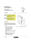
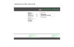
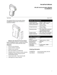
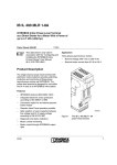
1
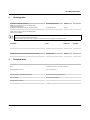
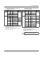
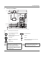
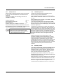
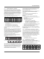
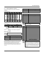
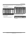
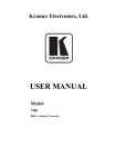
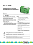
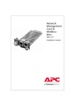
IB IL RS 485/422-PRO ...
Inline terminal for serial data transmission
2 x
AUTOMATION
Data Sheet
6985_en_05
1
© PHOENIX CONTACT - 03/2008
Description
The terminal is designed for use within an Inline station. It is
used to operate standard I/O devices with serial interfaces
on a bus system.
Difference between IB IL RS 485/422 ... and
IB IL RS 485/422-PRO ...:
IB IL RS 485/422 ...
Parameterization and data exchange are carried out via the
bus using PCP services.
Features
–
–
–
–
–
–
A serial I/O channel (RS-485 or RS-422)
Various protocols supported
Transmission speed can be set up to 38400 baud
Number of data bits, stop bits, and parity can be set
4 kbyte receive buffer and 1 kbyte transmit buffer
Parameterization and data exchange via the bus using
process data
IB IL RS 485/422-PRO ...
Parameterization and data exchange are carried out via the
bus using process data. This allows faster communication
times than with the IB IL RS 485/422.
This data sheet is only valid in association with the IL SYS PRO INST UM E user manual.
Make sure you always use the latest documentation.
It can be downloaded at www.download.phoenixcontact.com.
A conversion table is available on the Internet at www.download.phoenixcontact.com/general/7000_en_00.pdf.
This data sheet is valid for the products listed on the following page:
IB IL RS 485/422-PRO ...
2
Ordering data
Products
Description
Type
Order No.
Pcs./Pkt.
Inline terminal for serial data transmission,
complete with accessories (connector and labeling fields);
transmission speed 500 kbaud
IB IL RS 485/422-PRO-PAC
2863627
1
Inline terminal for serial data transmission, without accessories,
transmission speed 500 kbaud
IB IL RS 485/422-PRO
2863707
1
Inline terminal for serial data transmission,
complete with accessories (connector and labeling fields);
transmission speed 2 Mbaud
IB IL RS 485/422-PRO-2MBD-PAC
2878887
1
The listed connector set is needed for the complete fitting of the IB IL RS 485/422-PRO terminal.
When using the terminal according to the example
"RS-485: Terminal in the network center" on page 9 two shield connectors are required for connecting the cables.
Accessories
Description
Type
Order No.
Connector set with a standard connector and a shield connector
IB IL AO/CNT-PLSET
2732664
1 set
Shield connector
IB IL SCN-6 SHIELD
2736353
5
Documentation
Description
Type
Order No.
Pcs./Pkt.
"Automation Terminals of the Inline Product Range" user manual
IL SYS INST UM E
2698737
1
"INTERBUS Addressing" data sheet
DB GB IBS SYS ADDRESS
9000990
1
3
Pcs./Pkt.
Technical data
General data
Housing dimensions (width x height x depth)
24.4 mm x 136 mm x 72 mm (with connectors)
Weight
90 g (without connectors), 135 g (with connectors)
Operating mode
Process data mode with 6 words
Connection method for sensors
2 and 3-wire technology
Permissible temperature (operation)
-25°C to +55°C
Permissible temperature (storage/transport)
-25°C to +85°C
Permissible humidity (operation/storage/transport)
10% to 95% according to DIN EN 61131-2
Permissible air pressure (operation/storage/transport)
70 kPa to 106 kPa (up to 3000 m above sea level)
Degree of protection
IP20 according to IEC 60529
Class of protection
Class 3 according to EN 61131-2, IEC 61131-2
Connection data for connectors
Connection type
Spring-cage terminals
Conductor cross-section
0.2 mm2 to 1.5 mm2 (solid or stranded), 24 - 16 AWG
6985_en_05
PHOENIX CONTACT
2
IB IL RS 485/422-PRO ...
Interfaces
Bus
Local bus
Through data routing
Serial interfaces
Type
RS-485 half duplex or RS-422 full duplex
Cannot be operated simultaneously
Electrical data according to EIA (RS) 485, EIA (RS) 422, CCITT V.11
Line termination resistance
120 Ω typical
Permissible input differential voltage
±5.7 V maximum
Owing to the 120 Ω termination resistance the input differential voltage is limited to ±5.7 V.
Hysteresis
50 mV, typical
Input sensitivity
-0.2 V minimum, +0.2 V maximum
Output differential voltage (with 100 Ω load)
±2.0 V minimum
Output differential voltage (with 54 Ω load)
±1.5 V minimum
Short-circuit output current
±80 mA, typical
Transmission speed
IB IL RS 485/422-PRO
500 kbaud
IB IL RS 485/422-PRO-PAC
500 kbaud
IB IL RS 485/422-PRO-2MBD-PAC
2 Mbaud
Supply of the module electronics through the bus coupler
Connection method
Potential routing
Power consumption
500 kbps
Communications power UL
7.5 V
7.5 V
Current consumption at UL
170 mA, typical, 260 mA, maximum*
185 mA, typical, 260 mA, maximum*
Total power consumption
Approx. 1.275 W, typical,
1.950 W, maximum*
Approx. 1.388 W, typical,
1.950 W, maximum*
2 Mbps
* All connections of the serial interface are short-circuited.
ATTENTION: Defective module when continuously short-circuited
A continuous short circuit can damage the device. Therefore rule out continuous short circuits.
This terminal takes no current from the UM and US potential jumpers.
Power dissipation
Power dissipation in the module
PEL = 1.4 W
Power dissipation of the housing PHOU
1.4 W, maximum (within the permissible operating temperature)
Limitation of simultaneity, derating
TA ≤ 50°C
No derating
TA > 50°C
IQ = 4 A
IQ: Total diagonal routing current IM/IS/GND
Safety equipment
None
6985_en_05
PHOENIX CONTACT
3
IB IL RS 485/422-PRO ...
Electrical isolation/isolation of the voltage areas
Electrical isolation of the logic level from the serial interface is ensured by the DC/DC converter.
Common potentials
The serial interface control and data lines have the same potential. FE is a separate potential area.
Separate potentials in the system consisting of bus coupler/power terminal and I/O terminal
Test distance
Test voltage
5 V supply incoming remote bus / 7.5 V supply (bus logic)
500 V AC, 50 Hz, 1 min
5 V supply outgoing remote bus / 7.5 V supply (bus logic)
500 V AC, 50 Hz, 1 min
RS-485/422 interface / 7.5 V supply (bus logic)
500 V AC, 50 Hz, 1 min
RS-485/422 interface / 24 V supply (I/O)
500 V AC, 50 Hz, 1 min
RS-485/422 interface / functional earth ground
500 V AC, 50 Hz, 1 min
7.5 V supply (bus logic) / 24 V supply (I/O)
500 V AC, 50 Hz, 1 min
7.5 V supply (bus logic) / functional earth ground
500 V AC, 50 Hz, 1 min
24 V supply (I/O) / functional earth ground
500 V AC, 50 Hz, 1 min
Error messages to the higher-level control or computer system
None
Approvals
For the latest approvals, please visit www.download.phoenixcontact.com or www.eshop.phoenixcontact.com.
4
Diagnostic/status indicators and
terminal point assignment
D
T R
R x D
T x D
4.1
Local diagnostic and status indicators
Des.
Color
D
Green
TR
–
Serial interface:
RxD
Yellow
R S 4 8 5 /4 2 2
TxD
4.2
Meaning
Diagnostics
–
Terminal is receiving data from the
connected device
Yellow Terminal is transmitting data to the
connected device
Function identification
Orange
2 Mbps: white stripe in the vicinity of the D LED
2
1
1
2
1 .1
1
1
2 .1
1 .2
2
2
2 .2
1 .3
3
3
2 .3
1 .4
4
4
2 .4
6 1 9 9 A 0 0 3
Figure 1
6985_en_05
Diagnostic/status indicators and terminal point
assignment
PHOENIX CONTACT
4
IB IL RS 485/422-PRO ...
4.3
Terminal point assignment in the half-duplex
operating mode (RS-485)
Connec- Terminal Signal Assignment
tor
point
1
1.4, 2.4 FE
Functional earth
ground
2.3
GND GND*
All other terminal points of this
connector are not used.
2
1.1
TxD+ Reserved
2.1
TxD- Reserved
1.2
RxD+ Receive/transmit
data (positive)
2.2
RxD- Receive/transmit
data (negative)
1.3
R+
Termination
resistor (positive)
2.3
RTermination
resistor (negative)
1.4, 2.4 Shield Shield connection
*
Data
direction
Input/
output
Input/
output
For the IB IL RS 485/422-PRO (-PAC) terminal,
hardware version 01 or later. In all previous versions
terminal point 2.3 is not used.
For the IB IL RS 485/422-PRO-2MBD-PAC terminal,
hardware version 00 or later.
4.4
Terminal point assignment in the full-duplex
operating mode (RS-422)
Connec- Terminal Signal Assignment
tor
point
1
1.4, 2.4 FE
Functional earth
ground
2.3
GND GND*
All other terminal points of this
connector are not used.
2
1.1
TxD+ Transmit data
(positive)
2.1
TxD- Transmit data
(negative)
1.2
2.2
1.3
2.3
1.4, 2.4
*
Data
direction
Output
Output
RxD+
Receive data
Input
(positive)
RxD- Receive data
Input
(negative)
R+
Termination
resistor (positive)
RTermination
resistor (negative)
Shield Shield connection
For the IB IL RS 485/422-PRO (-PAC) terminal,
hardware version 01 or later. In all previous versions
terminal point 2.3 is not used.
For the IB IL RS 485/422-PRO-2MBD-PAC terminal,
hardware version 00 or later.
Observe the connection notes on page 7.
6985_en_05
PHOENIX CONTACT
5
IB IL RS 485/422-PRO ...
5
Internal circuit diagram
L o c a l b u s
U
U
U
O P C
D
L +
A N A
L -
2 4 V
R x D
5 V
T R
T x D
5 V
5 V
1
µ P
R S -4 8 5 /4 2 2
In te rfa c e
/
/
T x D +
+ 2 4 V (U S )
1
T x D -
R x D +
R x D -
R +
R -
+ 2 4 V (U M )
G N D
6 1 9 9 C 0 0 4
Figure 2
Internal wiring of the terminal points
Key:
Protocol chip (bus logic including
voltage conditioning)
OPC
x x x
R S -4 8 5 /4 2 2
In te rfa c e
/
µ P
RS-485/422 interface
Diagnostic and status indicators with
function information
Capacitor
Optocoupler
Resistor
DC/DC converter with electrical
isolation
X X X
/
1
Ground, electrically isolated from ground of the
communications power UL
Microprocessor
Hardware version 01 or later: GND is assigned to
terminal point 2.3 of the IB IL RS 485/
422-PRO (-PAC) terminal. In all previous
versions, this terminal point is not used. For the
IB IL RS 485/422-PRO-2MBD-PAC terminal with
hardware version 00 or later, the terminal point
2.3 is assigned to GND.
6985_en_05
Other symbols used are explained in the
IL SYS INST UM E user manual or in the Inline
system manual for your bus system.
PHOENIX CONTACT
6
IB IL RS 485/422-PRO ...
6
Serial interface
7
Connection notes
The terminal has an RS-485 and an RS-422 interface. The
interfaces can only be operated alternatively.
6.1
By assigning terminal points 1.4 and 2.4 of both
connectors you can connect the cable shield
either using a capacitor (connector 2) or directly
(connector 1) to functional earth ground (FE).
RS-485
In RS-485 operating mode, an RS-485 network with several
devices can be created.
The two connection options allow to connect one
cable shield side to FE directly and the other
capacitively - without additional effort. In this way,
you can prevent ground loops occurring if a shield
is connected directly to FE on both sides.
Use a data cable with commonly shielded twisted pairs to
connect the devices. Equip this data cable with a
termination resistor at both most remote points of the RS485 network. To connect them to the Inline terminal, use the
termination resistor installed in the device (see Figure 2).
No matter at what side you connect the shield,
you must connect all wires to connector 2.
Connection examples are shown in Figures 5 to 7 on pages
9 to 10.
Use at least one connector with shield connection
when connecting the I/O device.
This operating mode supports the half-duplex transmission.
Make sure that only one device is transmitting data at a time.
In order to be able to guarantee a defined cable idle state,
the data cable polarization is contained in the terminal.
6.2
7.1
Shield connected capacitively to FE
RS-422
In RS-422 operating mode, it is possible to establish a pointto-point connection.
Use a data cable with commonly shielded twisted pairs to
connect the devices. Equip this data cable with a
termination resistor at each device. To connect them to the
Inline terminal, use the termination resistor installed in the
device (see Figure 2).
6 8 7 8 B 0 0 5
Connection examples are shown in Figures 8 to 9 on pages
10 to 11.
Figure 3
This operating mode supports full-duplex transmission.
7.2
Position of the shield connector to connect the
shield capacitively to FE
Shield connected directly to FE
6 8 7 8 B 0 0 6
Figure 4
6985_en_05
Position of the shield connector to connect the
shield directly to FE
PHOENIX CONTACT
7
IB IL RS 485/422-PRO ...
8
Connection examples
8.1
Comparison of the connection examples in Figure 5 to Figure 9
Operating
mode
Special remark
Shield
connection
Comment
RS-485
IB IL RS 485/422-PRO terminal
as network end point
IB IL RS 485/422-PRO in the
network center
IB IL RS 485/422-PRO terminal
as network end point
Shield connected capacitively to
FE
Shield connected directly
Capacitive
Termination resistor
required
–
RS-485
RS-485
RS-422
RS-422
Capacitive/
direct
Direct
Capacitive
Direct
Termination resistor
required
Termination resistor
required
Termination resistor
required
Required connectors Example
per
in
IB IL RS 485/422-PRO
Connector set
Figure 5
2 shield connectors
Figure 6
Connector set
Figure 7
Connector set
Figure 8
Connector set
Figure 9
The connector set consists of a shield connector
and a standard connector.
For connection, please observe the following notes:
–
–
–
Always connect the shield between two devices on one
side using a capacitor and on the other side directly to
FE.
An RS-485 network must be equipped with termination
resistors at both ends.
For an RS-422 point-to-point connection, the receive
signals on every device must be fitted with termination
resistors.
6985_en_05
PHOENIX CONTACT
8
IB IL RS 485/422-PRO ...
8.2
RS-485: Terminal as network end point
Connect the shield to FE using a capacitor.
Connector 1
2
IB IL RS 485/422-PRO ...
TxD+ 1.1
TxD- 2.1
D
TR
RxD
TxD
RS485/422
1
2
1
2
1
11
1
2
22
2
3
33
3
4
44
4
RxD+ 1.2
Transmit/receive data (positive)
RxD- 2.2
Transmit/receive data (negative)
R+
1.3
R-
2.3
Termination resistor connection
via R+ and R-
Inline connector
(connector 2)
RS 485
RS 485
RS 485
6199B008
Figure 5
8.3
RS-485 interface wiring: IB IL RS 485/422-PRO ... as the end point of a network,
data line shield connected to FE using a capacitor
RS-485: Terminal in the network center
1
Connector
2
IB IL RS 485/422-PRO ...
TxD+ 1.1
RxD
TxD
RS 485
RS 485
RxD+ 1.2
RxD- 2.2
RS485/422
1
Transmit/
receive data
(positive)
Transmit/
receive data
(negative)
TxD- 2.1
D
TR
2
1
2
1
11
1
2
22
2
3
33
3
4
44
4
R+
1.3
R-
2.3
Inline connector
(connector 2)
RS 485
RS 485
RS 485
6199B009
Figure 6
6985_en_05
RS-485 interface wiring: IB IL RS 485/422-PRO ... in the center of a network,
data line shield directly and connected capacitively to FE
PHOENIX CONTACT
9
IB IL RS 485/422-PRO ...
8.4
RS-485: Terminal as network end point
Connect the shield directly to FE.
Connector 1
2
IB IL RS 485/422-PRO ...
TxD+ 1.1
TxD-
2.1
Transmit/receive data (positive)
RxD+ 1.2
Tranmit/receive data (negative)
RxD- 2.2
Termination resistor connection
via R+ and R-
R+
1.3
R-
2.3
Inline connector
(connector 2)
RS 485
RS 485
D
TR
RxD
TxD
RS485/422
1
2
1
2
1
11
1
2
22
2
3
33
3
4
44
4
6199B010
Figure 7
8.5
RS-422: Shield connected capacitively to the terminal
Connector
1 2
D
TR
RxD
TxD
RS485/422
1
RS-485 interface wiring: IB IL RS 485/422-PRO ... as the end point of a network,
data line shield connected directly to FE
2
1
2
1
11
1
2
22
2
3
33
3
4
44
4
IB IL RS 485/422-PRO ...
RS-422 device
TxD+ 1.1
Transmit data (positive)
Receive data (positive)
TxD- 2.1
Transmit data (negative)
Receive data (negative)
RxD+ 1.2
Receive data (positive)
Transmit data (positive)
RxD- 2.2
Receive data (negative)
Transmit data (negative)
R+
1.3
R-
2.3
Inline connector
(connector 2)
Termination resistor
connection via
R+ and R-
Termination resistor
connection
RS 422
6199C011
Figure 8
6985_en_05
RS-422 interface wiring: Data line shield connected capacitively to FE
PHOENIX CONTACT
10
IB IL RS 485/422-PRO ...
8.6
RS-422: Shield directly connected to the terminal
Connector
1 2
IB IL RS 485/422-PRO ...
TxD+ 1.1
RxD
TxD
RS485/422
1
Transmit data (positive)
Receive data (positive)
Transmit data (negative)
Receive data (negative)
RxD+ 1.2
Receive data (positive)
Transmit data (positive)
RxD- 2.2
Receive data (negative)
Transmit data (negative)
TxD-
D
TR
2
1
2
1
11
1
2
22
2
3
33
3
4
44
4
RS-422 device
2.1
R+
1.3
R-
2.3
Inline connector
(connector 2)
Termination resistor
connection via
R+ and R-
Termination resistor
connection
RS 422
6199C012
Figure 9
RS-422 interface wiring: Data line shield directly connected to FE
9
Programming data/configuration
data
9.1
Local bus (INTERBUS)
ID code
Length code
Process data channel
Input address area
Output address area
Parameter channel (PCP)
Register length (bus)
9.2
BFhex (191dec)
06hex
96 bits
12 bytes
12 bytes
0 bytes
12 bytes
Other bus systems
For the programming data/configuration data of
other bus systems, please refer to the
corresponding electronic device data sheet (e.g.,
GSD, EDS).
6985_en_05
PHOENIX CONTACT
11
IB IL RS 485/422-PRO ...
10
Data storage and transmission
The terminal stores the received serial data in an
intermediate buffer until it is fetched from the serial interface
by the bus controller board or the device. Serial data traffic
can be managed using various protocols. The protocol used
depends on the type of protocol supported by the peers.
10.1
Overview of supported protocols
Protocol Receive
buffer
Transmit
memory
Transpar- 4096 bytes
ent
End-to25 buffers
end
with 11 bytes
each
Dual
2 buffers with
buffer
11 bytes
each
1023 bytes
Special
features when
receiving
Two end
characters are
filtered out
Only stores the
most recently
received data,
end characters
are filtered out
5 buffers with Data exchange
25 buffers
with 11 bytes 330 bytes
with software
handshake,
each
each
time monitoring,
and checksum
4096 bytes
1023 bytes
Software
handshake
11 bytes
11 bytes
Data exchange
with time
monitoring and
check sum
3964R
XON/
XOFF
Movilink
1023 bytes
(including end
characters)
1023 bytes
(including end
characters)
The Movilink protocol is available for firmware
Version 1.10 or later.
10.2
Transparent protocol
If the transparent protocol is used, serial data is transmitted
through the terminal in the same format it was received from
the serial interface or the bus side.
10.3
End-to-end protocol
The serial data is conditioned for the end-to-end protocol.
If serial data is sent from the bus side, two additional
characters, the first and second delimiters, are attached for
transmission to the serial interface. The first and second
delimiters are defined upon terminal configuration.
Serial data sent from the serial interface can only be read by
the user if the terminal has received the first and second
delimiters. Both delimiters confirm that the serial data has
been received without error and the maximum data length of
11 bytes has been observed. The delimiters are filtered out
when the data is read by the bus side.
Unlike in the transparent protocol, the receive memory is not
organized as a FIFO but as a buffer. 25 buffers with 11 bytes
each are available. If the buffer size of 11 bytes is exceeded,
without the two delimiters being detected, the buffer is
overwritten again.
The transmit FIFO consists of 1023 bytes. The delimiters
are attached to, and stored with, the data to be sent.
10.4
Dual buffer protocol
With this protocol, the last received data block is stored. A
data block is defined as a sequence of characters with the
first and second delimiter end characters, as in the end-toend protocol.
As soon as a new data block is received, the previous one is
overwritten. This is achieved by means of two buffers, which
are written alternately. In this way, there is always one buffer
ready to receive serial data while the second buffer stores
the most recently received data block. A data block is only
regarded as complete once both delimiters have been
detected, one after the other. It can then be read from the
bus side.
If the buffer size of 11 bytes is exceeded, without the two
delimiters being detected, the buffer is overwritten again.
When transmitting serial data, the same is valid as for the
end-to-end protocol: If serial data is sent from the bus side,
two additional characters, the first and second delimiters,
are attached for transmission to the serial interface.
The transmit FIFO (First-In-First-Out memory) can store
1023 bytes (1 kbyte) and the receive FIFO can store 4096
bytes (4 kbytes). If the terminal receives another character
after the 4095th character, the error pattern is stored in the
receive FIFO. All further characters are ignored.
6985_en_05
PHOENIX CONTACT
12
IB IL RS 485/422-PRO ...
10.5
3964R protocol
10.6
This protocol, developed by Siemens, is the most complex.
It uses start and end identification, checksum and time
monitoring.
5 buffers are available for transmitting, 25 buffers are
available for receiving.
Character delay time:
Acknowledgment delay time:
Block waiting time:
Number of attempts to establish a connection:
220 ms
2s
10 s
6
The optional 3964 priority defines which device may send
first (high priority) if there is an initialization conflict (several
devices attempting to send data simultaneously).
As the RS-485 interface is a half duplex interface
a waiting time (slave response time) is kept
between data transmission and reception. It is
11 bits and depends on the baud rate.
XON/XOFF protocol
This protocol operates like the transparent protocol,
however, using a software handshake.
Data transmission with this protocol is controlled by the
XON and XOFF characters. XON is set to 11hex and XOFF
to 13hex.
If the terminal receives an XOFF, no more serial data will be
sent until an XON is received.
The terminal itself will transmit an XOFF if the available
space in the receive memory is less than 5 bytes. As soon
as more memory becomes available again, the module will
transmit a single XON.
Transmission of serial data is not filtered. Any characters,
which occur with the code defined for XON and XOFF, are
thus transmitted and may trigger undesirable events at the
receiver. When serial data is received, the XON and XOFF
characters are filtered and are not available as data. Any
characters with the XON or XOFF code are lost. Ensure that
characters with these codes do not appear in the data
stream.
With the XON/XOFF protocol this function is only
completely available for the RS-422 interface. It can be
discussed if using the protocol for the RS-485 interface is
useful as the latter is a half duplex connection, which
enables either to transmit or to receive data. However, with
the XON/XOFF protocol the receiver can respond with a
XOFF at any time when transmitting characters. Reception
of this control character by the transmitter is thus not
ensured.
10.7
Movilink protocol
The terminal is the Movilink master in the Movilink protocol.
After transmission of a telegram the terminal waits for a
maximum of 500 ms for the response. After the response
was received, the response data is available in the input
data. Only then can the next telegram be sent.
A delimiter is placed ahead of the process data when a
Movilink telegram is being sent. The calculated checksum is
added behind the process data.
When the data is received, the delimiter and the checksum
are filtered out before the data is transmitted over the bus.
Transmit or receive errors are reported when a transmission
timeout or a negative checksum comparison occurs.
Transmit and receive buffer have a size of 11 bytes each.
6985_en_05
PHOENIX CONTACT
13
IB IL RS 485/422-PRO ...
11
11.1
Process data
The terminal process image comprises six data words each
in input and output direction.
For the assignment of the illustrated (word.bit) or
(byte.bit) view to your INTERBUS control system
or computer system, please refer to the
DB GB IBS SYS ADDRESS data sheet.
4 3
x x
2 1 0
x x x
15 14 13 12 11 10 9 8 7 6 5
Command IN parameter x x x
4 3
x x
2 1 0
x x x
Status word
Err: error
x = 0 or 1; the assignment depends on the command.
0
3
2
5
4
7
6
9
8 11 10
000
Data
Data
Data
Data
Data
Data
Data
1
Data
Code
(Bin)
Data
9 10 11
Data
8
Data
7
Data
6
Data
5
Data
4
Data
3
Data
2
Data
1
Data
5
Data
4
Data
3
Data
2
7 6 5
x x x
0
Status Command/
parameter parameter
OUT
IN
1
15 14 13 12 11 10 9 8
OUT
0 Command
parameter
Data
0
Control word
Err
The terminal has six process data words.
Word
Byte in
the
Motorola
format
Byte in
the Intel
format
Word 0 general
The byte representation in the Motorola format,
also called Big Endian (high order byte at starting
address) corresponds to the INTERBUS
standard representation. All byte representations
in the data sheet have this format.
The byte representation in the Intel format is also
called Little Endian (low order byte at starting
address).
The command is used to determine the function. The
actually transmitted data depends on the command.
001
010
011
100
101
110
111
Code
Command
(hex)
(with
bit 15 = 0)
0
Read status bits. Input word 1
contains the number of characters
received.
1
Transmit characters
2
Buffer characters
(not in the Movilink protocol)
3
Read characters.
Parameter = Chex: Read FW version,
Parameter = Dhex: Read
configuration
4
Write configuration
5
Toggle command 1:
transmit characters
6
Toggle command 2:
Buffer characters
(not in the Movilink protocol)
7
Toggle command 3:
Read characters
(not in the Movilink protocol)
Command toggling
Command toggling is used to execute a command on a
terminal again. In this way a second command code is
available for the same function. This applies for the following
commands:
– Transmit characters
– Buffer characters (not in the Movilink protocol)
– Read characters (not in the Movilink protocol)
Here, bit 14 is used for toggling.
6985_en_05
PHOENIX CONTACT
14
IB IL RS 485/422-PRO ...
11.2
"Read Status Bits" command
Control word MSB
15
LSB
14
13
12
0
0
0
11
10
9
8
7
6
5
4
3
2
1
0
Receive error
0: No action
1: Reset receive error
Transmit error
0: No action
1: Reset transmit error
Status word
MSB
15
LSB
14
13
12
0
0
0
11
10
9
Number of
received
data
8
7
6
5
Reserved
Transmit buffer
4
3
1
0
Reserved
Receive buffer
0: Empty
1: Not empty
0: Empty
1: Not empty
Transmit butter
0: Not full
1: Full
Figure 10
2
Receive error
0: No error
1: Error
Receive buffer
Transmit error
0: Not full
1: Full
0: No error
1: Error
6985D001
Format of the process data word 0
In the Movilink protocol bits 8 to 11 in the status
word have no meaning.
Bit/status
Bit 0 = '1'
Bit 1 = '1'
Bit 2 = '1'
Bit 3 = '1'
Bit 4 = '1'
6985_en_05
Effect
The receive buffer is not empty, there are characters to be read.
Protocol
All excluding
Movilink
The receive error indicates that a 3964R telegram could not be received without error after six 3964R
transmit attempts by the serial peer or after the block waiting time had elapsed.
The receive error indicates that
Movilink
– a parity error occurred while the response was received,
– the first character received is not SD2,
– the checksum test was negative,
– the number of received characters is unequal to the number of transmitted characters.
The transmit error indicates that a 3964R telegram could not be transmitted from the module 3964R
to the serial peer without error after six transmit attempts. The telegram was rejected.
The transmit error indicates, that the set timeout of 500 ms elapsed and a response has not Movilink
yet been received.
Reserved
The receive buffer is full:
Transparent,
end-to-end,
Transparent and XON/XOFF protocol:
Residual capacity: <15
3964R, XON/
characters
XOFF
3964R and end-to-end protocol:
Residual capacity: none
PHOENIX CONTACT
15
IB IL RS 485/422-PRO ...
Bit/status
Bit 5 = '1'
Bit 6 = '1'
Bit 7 = '1'
Bits 8 to 11
Effect
The transmit buffer is full:
3964R protocol:
Dual buffer, transparent, end-to-end, and XON/XOFF
protocol:
Residual capacity: none
Residual capacity: ≤30
characters
The transmit buffer is not empty, there are characters to be transmitted.
The transmit buffer is not empty, there are characters to be transmitted.
This bit is set during the entire data transmission.
Reserved
Number of characters received. If the code = Fhex, more than 14 characters have been
received.
Protocol
All excluding
Movilink
All excluding
Movilink
Movilink
All excluding
Movilink
With the "Read Status Bits" command the content of the
input data is continuously updated. Unlike with other
commands toggling is not required.
Both error bits (bits 1 and 2) are not automatically
reset. They can only be reset by the process data
output word.
In the transparent and XON/XOFF protocols, the
input word 1 contains the total number of
characters received.
6985_en_05
PHOENIX CONTACT
16
IB IL RS 485/422-PRO ...
11.3
"Transmit Characters" command
Process data is stored in the transmit memory and then
directly transmitted via RS-485 or RS-422. A maximum of
eleven characters can be transmitted. The OUT parameter
determines the number of characters to be transmitted.
Characters stored in the intermediate buffer are transmitted
first. After the command has been executed successfully
the intermediate buffer is cleared.
Process data assignment for the "Transmit Characters"
command with eleven characters (C1 - C11)
The start delimiter of the request telegram (SD1) and the
response telegram (SD2) are defined as follows:
SD1 = 02hex, SD2 = 1Dhex.
The error bit (bit 15 in the status word, i.e. in the first word
received (Wort 0)) indicates the acknowledgment:
Error bit = 0:
Data transmission is okay, the data behind byte 1 is
response data of the Movilink peer.
Reasons for an error bit set:
– OUT parameter = 0 and intermediate buffer empty
– OUT parameter >11
– Not enough space in the transmit memory
– Not enough space in the intermediate buffer
Error bit = 1:
An error has occurred. It may have several causes:
– The length information in the output data is equal to 0 or
larger than 11.
– The Movilink response is invalid;
The options are as follows:
– The first character is unequal SD2.
– The checksum comparison is negative.
– The number of received characters is unequal to
the number of transmitted characters.
– Parity errors occurred while the response was received.
– The timeout period elapsed, which means that no
response was received within 500 ms.
"Transmit Characters" command for the Movilink
protocol
Set the toggle bit for the next transfer in the command. If
command 1 was used before, command 5 will be sent. Then
command 1 again.
0
Word
Byte
OUT
IN
0
1
C
1Bhex
1
1Bhex –
1
2
C
2
–
2
3
C
3
–
4
C
4
–
3
5
C
5
–
6
C
6
–
4
7
C
7
–
8
C
8
–
5
9
C
9
–
10
C1
0
–
11
C1
1
–
After the command 1hex or 5hex was received over the bus,
the terminal generates a Movilink telegram. The process
data length is specified in the first byte (in the example Ahex
= 10 bytes). The SD1 start delimiter is placed ahead of the
process data in the telegram. The calculated checksum is
added behind the process data. The checksum is
calculated over the complete telegram.
Process data assignment for the "Transmit Characters"
command with 10 characters (C1 - C10)
Output data
5
0
3
Word
1
2
4
Byte
0
1 2 3 4 5 6 7 8 9 10 11
OUT 1Ahex C1 C2 C3 C4 C5 C6 C7 C8 C9C10 _
11.4
"Store Characters Temporarily" command
The transmit data is stored in an intermediate buffer, which
can store 330 characters. No characters are transmitted.
The OUT parameter determines the number of characters.
The "Transmit Characters" command is used for transmitting the data stored temporarily. In this way character
blocks of up to 330 characters can be transmitted. They are
divided over 20 telegrams with 11 characters each.
Reasons for an error bit set:
– OUT parameter = 0 or >11
– Not enough space in the intermediate buffer
11.5
"Read Characters" command
Movilink telegram
Delimiter Address
Type
User
data
Checksum
6985A003
The command is only acknowledged over the bus, when
either the response of the Movilink peer was received or the
timeout period of 500 ms elapsed. When there is a positive
acknowledgment (error bit = 0) the process input data
contains the response data. Start delimiter and checksum
have been filtered out from the response.
This command is used to read a maximum of eleven
characters. The IN parameter contains the number of valid
characters available in the input data.
Process data assignment for the "Read Characters"
command with eleven characters (C1 - C11)
Word
Byte
OUT
IN
6985_en_05
0
0
1
30hex –
C
3Bhex
1
1
2
–
C
2
2
3
–
C
3
4
–
C
4
3
5
–
C
5
6
–
C
6
4
7
–
C
7
8
–
C
8
5
9
–
C
9
10
–
C1
0
PHOENIX CONTACT
11
–
C1
1
17
IB IL RS 485/422-PRO ...
11.6
"Write Configuration" command
Output type
Process data assignment for the "Write Configuration"
command
Code
Meaning
Output words 0 to 5
0hex
RS-485
1hex
RS-422
Code
Meaning
00hex
Transparent
01hex
End-to-end
02hex
Dual buffer
IN
–
–
5
6
4
7
8
5
9
10 11
–
–
–
–
–
Reserved
Reserved
Protocol
Reserved
Baud rate/data width
–
4
Direct baud rate
3
2nd delimiter
2
3
1st delimiter
1
Output type/protocol
2
0
40hex
OUT
1
Error pattern
0
40hex
Word
Byte
–
–
–
03hex
3964R with low priority
04hex
3964R with high priority
05hex
XON/XOFF
06hex
Movilink
Output word 1
7
6
5
Byte 2
4 3 2
1
Protocol
Output type:
0: RS 485
1: RS 422
Figure 11
0
7
6
5
Byte 3
4 3 2
Baud rate
The Movilink protocol is available for firmware
Version 1.10 or later.
1
0
Baud rate
Data width
6985B002
Output word 1 in the "Write Configuration"
command
Element value range
The options in bold are default settings.
Error pattern
Code
Value
00hex
110 baud
01hex
300 baud
02hex
600 baud
03hex
1200 baud
04hex
1800 baud
05hex
2400 baud
06hex
4800 baud
07hex
9600 baud
08hex
19200 baud
Meaning
09hex
38400 baud
24hex
$
0Dhex
Directly, basis 500 kbaud
xxhex
Any character
0Ehex
Directly, basis 62.5 kbaud
0Fhex
Directly, basis 15625 baud
Code
The error pattern contains the character that is written into
the FIFO, if a character was received with an error (not valid
for the 3964R protocol). Reasons are e.g. parity errors,
exceeded value range, superimposed noise. In the
transparent and XON/XOFF protocols, the pattern is also
used if the receive FIFO is full and further characters are
received.
6985_en_05
The specified baud rates of 110 baud to
38400 baud are adequate for most applications.
However, you can freely choose the baud rate by
means of direct programming. For this, use the
0Dhex, 0E hex and 0Fhex baud rate codes in the
output word 1, see "Direct Baud Rate (DBC)" on
page 19.
PHOENIX CONTACT
18
IB IL RS 485/422-PRO ...
Data width
Code
Meaning
00hex
Representation in CMD/PC WORX
Data bits
Parity
Stop bits
7
even
1
7 data bits, even parity, 1 stop bit
01hex
7
odd
1
7 data bits, odd parity, 1 stop bit
02hex
8
even
1
8 data bits, even parity, 1 stop bit
03hex
8
odd
1
8 data bits, odd parity, 1 stop bit
04hex
8
None
1
8 data bits, without parity, 1 stop bit
05hex
7
None
1
7 data bits, without parity, 1 stop bit
06hex
7
even
2
7 data bits, even parity, 2 stop bits
07hex
7
odd
2
7 data bits, odd parity, 2 stop bits
08hex
8
even
2
8 data bits, even parity, 2 stop bits
09hex
8
odd
2
8 data bits, odd parity, 2 stop bits
0Ahex
8
None
2
8 data bits, without parity, 2 stop bits
0Bhex
7
None
2
7 data bits, without parity, 2 stop bits
Direct Baud Rate (DBC)
First delimiter
Code
Meaning
0Dhex
Carriage Return (CR)
xxhex
Any character
Choose direct programming of the baud rate in the output
word 1 by means of the 0Dhex, 0Ehex and Fhex baud rate
codes. You can select a basic clock for the baud rate. The
actual baud rate is calculated according to the following
formula:
Second delimiter
Baud rate = basic clock / (DBC + 1)
Code
Meaning
0Ahex
Line Feed (LF)
xxhex
Any character
Specify DBC in the output byte 6. To determine DBC
change the equation to read:
DBC = basic clock / baud rate - 1
The first delimiter and the second delimiter contain the
end characters for the dual buffer and the end-to-end
protocols.
After successful configuration the characters for
the receive and transmit FIFO are reset. In this
way, all transmit and receive data that have not
yet been processed will be deleted.
Reasons for an error bit set:
– Using a reserved code
– Setting a reserved bit
– Baud rate 110 baud or 300 baud in the 3964 protocol
6985_en_05
Example:
The baud rate is 15625 baud. A basic baud rate of 500
kbaud (code 0Dhex) is chosen. Determine the direct baud
rate:
DBC = (500000 baud / 15625 baud) - 1 = 31dec =
1Fhex
An example for the first four output words is:
40 00 00 D2 00 00 1F hex.
Programming of the direct baud rate theoretically
enables a maximum value of 500 kbaud. Proper
operation of the terminal is tested and guaranteed
for up to 38400 baud. Operation with higher baud
rates depends on the application.
PHOENIX CONTACT
19
IB IL RS 485/422-PRO ...
Example for a configuration with transparent protocol
11.7
–
–
–
–
Process data assignment for the "Read Configuration"
command
–
–
–
–
–
–
–
–
Example for a configuration with Movilink protocol
–
–
–
–
Default: Movilink protocol
Baud rate: 9600 baud
Data width: 8 data bits with odd parity and one stop bit
Configuration (in hex): 4000 0672 0000 0000
11.8
x
x
x
00
00
10 11
00
x
00
5
9
x
x
Direct baud rate
8
00
x
2 nd delimiter
7
x
IN
6
1st delimiter
OUT
10 11
5
x
Reserved
–
–
9
4
Baud rate/data width
Direct baud rate
OUT 40 00 00 83 00 00 00
IN
40 – – – – – –
8
3
4
x
7
2
3
Output type/protocol
6
1
2
x
5
0
1
Error pattern
4
0
3Dhex
3
Reserved
2
5
Reserved
1
Meaning
0
2nd delimiter
4
1st delimiter
3
Baud rate/data width
2
Output type/protocol
1
Error pattern
0
40hex
Word
Byte
Word
Byte
3Dhex
Default: Transparent protocol
Baud rate: 19200 baud
Data width: 8 data bits with odd parity and one stop bit
Configuration (in hex): 4000 0083 0000 0000
"Read Configuration" command
"Read Firmware Version" command
With a control word of 3C00hex, the second input word
supplies the firmware version and the type code.
15 14 13 12 11 10 9 8 7 6 5
Firmware version, e.g.,100hex
4
3 2 1 0
Type code:
7hex
Type code 7hex is identical with the type code of
IB IL RS 485/422 ....
6985_en_05
PHOENIX CONTACT GmbH & Co. KG • 32823 Blomberg • Germany • Phone: +49-(0) 5235-3-00
PHOENIX CONTACT • P.O.Box 4100 • Harrisburg • PA 17111-0100 • USA • Phone: +717-944-1300
www.phoenixcontact.com
20