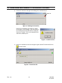
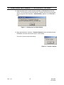
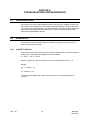
1
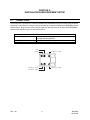
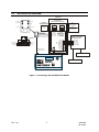
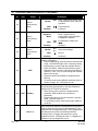
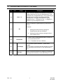
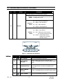
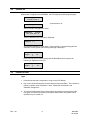
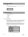
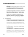
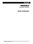
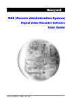
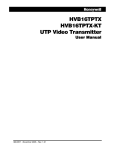
HEGS5BLX
Keyboard Controller
User Guide
900.0799 – June 2006 - Rev 1.01
ISSUE
DATE
REVISIONS
900.0723
1.0
May 2006
Initial Release
900.0799
1.0
June 2006
Correct controller power supply part #/add power supply
part # to converter; correct RS232 RX/TX terminals on
terminal block
1.01
June 2006
Revise connections to power connector
Rev. 1.01
ii
900.0799
20-Jun-06
FCC COMPLIANCE STATEMENT
INFORMATION TO THE USER: This equipment has been tested and found to comply
with the limits for a Class A digital device, pursuant to part 15 of the FCC rules. These
limits are designed to provide reasonable protection against harmful interference when
the equipment is operated in a commercial environment. This equipment generates,
uses, and can radiate radio frequency energy and, if not installed and used in
accordance with the instruction manual, may cause harmful interference to radio
communications. Operation of this equipment in a residential area is likely to cause
harmful interference in which case the user will be required to correct the interference at
his own expense.
CAUTION: Changes or modifications not expressly approved by the party responsible
for compliance could void the user’s authority to operate the equipment.
This Class A digital apparatus complies with Canadian ICES-003.
Cet appareil numérique de la Classe A est conforme à la norme NMB-003 du Canada.
USERS OF THE PRODUCT ARE RESPONSIBLE FOR CHECKING AND
COMPLYING WITH ALL FEDERAL, STATE, AND LOCAL LAWS AND
STATUTES CONCERNING THE MONITORING AND RECORDING OF
VIDEO AND AUDIO SIGNALS. HONEYWELL VIDEO SYSTEMS SHALL
NOT BE HELD RESPONSIBLE FOR THE USE OF THIS PRODUCT IN
VIOLATION OF CURRENT LAWS AND STATUTES.
Rev. 1.01
iii
900.0799
20-Jun-06
Rev. 1.01
iv
900.0799
20-Jun-06
IMPORTANT SAFEGUARDS
1.
READ INSTRUCTIONS – All safety and operating instructions should be read before the unit is
operated.
2.
RETAIN INSTRUCTIONS – The safety and operating instructions should be retained for future
reference.
3.
HEED WARNINGS – All warnings on the unit and in the operating instructions should be adhered
to.
4.
FOLLOW INSTRUCTIONS – All operating and use instructions should be followed.
5.
CLEANING – Unplug the unit from the outlet before cleaning. Do not use liquid cleaners or
aerosol cleaners. Use a damp cloth for cleaning.
6.
ATTACHMENTS – Do not use attachments not recommended by the product manufacturer as
they may result in the risk of fire, electric shock, or injury to persons.
7.
WATER AND MOISTURE – Do not use this unit near water or in an unprotected outdoor
installation, or any area which is classified as a wet location.
8.
ACCESSORIES - Do not place this product on an unstable cart, stand, tripod,
bracket, or table. The product may fall, causing serious injury to a child or adult and
serious damage to the equipment. Use only with a cart, stand, tripod, bracket, or
table recommended by the manufacturer, or sold with the product. Any mounting of
the product should follow the manufacturer’s instructions and should use a mounting
accessory recommended by the manufacturer. Wall or shelf mounting should follow the
manufacturer’s instructions and should use a mounting kit approved by the manufacturer.
9.
A product and cart combination should be moved with care. Quick stops, excessive force, and
uneven surfaces may cause the product and cart combination to overturn.
10.
VENTILATION - Slots and openings in the cabinet and the back or bottom are provided for
ventilation and to ensure reliable operation of the equipment and to protect it from overheating.
These openings must not be blocked or covered. The openings should never be blocked by
placing the product on a bed, sofa, rug, or other similar surface. Equipment should never be
placed near or over a radiator or heat register. This product should not be placed in a built-in
installation, such as a bookcase or rack unless proper ventilation is provided or the manufacturer’s
instructions have been adhered to.
11.
POWER SOURCES – This product should be operated only from the type of power source
indicated on the marking label. If you are not sure of the type of power supplied to your home,
consult your product dealer or local power company. For products designed to operate from
battery power or other sources, refer to the operating instructions.
12.
GROUNDING OR POLARIZATION – The power supply supplied with this unit may be equipped
with a polarized alternating-current line plug (a plug having one blade wider than the other). This
plug will fit into the power outlet only one way. This is a safety feature. If you are unable to insert
the plug fully into the outlet, try reversing the plug. If the plug should still fail to fit, contact your
electrician to replace your obsolete outlet. Do not defeat the safety purpose of the polarized plug.
13.
OVERLOADING – Do not overload outlets and extension cords as this can result in a risk of fire or
electric shock.
Rev. 1.01
v
900.0799
20-Jun-06
IMPORTANT SAFEGUARDS
14.
POWER-CORD PROTECTION – Power supply cords should be routed so that they are not likely
to be walked on or pinched by items placed upon or against them, paying particular attention to
cords and plugs, convenience receptacles, and the point where they exit from the monitor.
15.
OBJECT AND LIQUID ENTRY – Never push objects of any kind into this unit through openings as
they may touch dangerous voltage points or short-out parts that could result in a fire or electric
shock. Never spill liquid of any kind on the unit.
16.
SERVICING – Do not attempt to service this unit yourself as opening or removing covers may
expose you to dangerous voltage or other hazards. Refer all servicing to qualified service
personnel.
17.
DAMAGE REQUIRING SERVICE – Unplug the unit from the outlet and refer servicing to qualified
service personnel under the following conditions:
a. When the power-supply cord or plug is damaged.
b. If liquid has been spilled, or objects have fallen into the unit.
c.
If the unit has been exposed to rain or water.
d. If the unit does not operate normally by following the operating instructions. Adjust only those
controls that are covered by the operating instructions as an improper adjustment of other
controls may result in damage and will often require extensive work by a qualified technician to
restore the unit to its normal operation.
e. If the unit has been dropped or the enclosure has been damaged.
f.
When the unit exhibits a distinct change in performance - this indicates a need for service.
18.
REPLACEMENT PARTS – When replacement parts are required, be sure the service technician
has used replacement parts specified by the manufacturer or have the same characteristics as the
original part. Unauthorized substitutions may result in fire, electric shock or other hazards.
19.
SAFETY CHECK – Upon completion of any service or repairs to this unit, ask the service
technician to perform safety checks to determine that the unit is in proper operating condition.
20.
LIGHTNING AND POWER LINE SURGES – For added protection of this unit during a lightning
storm, or when it is left unattended and unused for long periods of time, unplug it from the wall
outlet and disconnect the cable system. This will prevent damage to the unit due to lightning and
power-line surges.
21.
HEAT – The product should be situated away from heat sources such as radiators, heat registers,
stoves, or other products (including amplifiers) that produce heat.
22.
INSTALLATION – Do not install the unit in an extremely hot or humid location, or in a place
subject to dust or mechanical vibration. The unit is not designed to be waterproof. Exposure to
rain or water may damage the unit.
23.
WALL OR CEILING MOUNTING – The product should be mounted to a wall or ceiling only as
recommended by the manufacturer
Rev. 1.01
vi
900.0799
20-Jun-06
EXPLANATION OF GRAPHICAL SYMBOLS
The lightning flash with arrowhead symbol within an equilateral triangle is intended to
alert the user to the presence of uninsulated "dangerous voltage" within the product's
enclosure that may be of sufficient magnitude to constitute a risk of electric shock to
persons.
The exclamation point within an equilateral triangle is intended to alert the user to the
presence of important operating and maintenance (servicing) instruction in the literature
accompanying the product.
CAUTION
CAUTION
RISK OF ELECTRIC SHOCK
DO NOT OPEN
CAUTION: TO REDUCE THE RISK OF ELECTRIC SHOCK,
DO NOT REMOVE COVER (OR BACK).
NO USER-SERVICEABLE PARTS INSIDE.
REFER SERVICING TO QUALIFIED SERVICE PERSONNEL.
WARNING
WARNING: TO REDUCE THE RISK OF FIRE OR ELECTRIC SHOCK, DO
NOT EXPOSE THIS PRODUCT TO RAIN OR MOISTURE.
WARNING: DO NOT INSERT ANY METALLIC OBJECT THROUGH
VENTILATION GRILLS THIS PRODUCT TO RAIN OR MOISTURE.
WARNING: THIS UNIT MUST BE OPERATED WITH A PROPERLY
GROUNDED 3-PIN CONNECTION.
NON-OBSERVANCE OF THIS STANDARD PRACTICE MAY RESULT IN A
STATIC ELECTRICITY BUILD-UP THAT MAY RESULT IN AN ELECTRIC
SHOCK WHEN EXTERNAL CONNECTIONS ARE TOUCHED.
Rev. 1.01
vii
900.0799
20-Jun-06
Notes:
Rev. 1.01
viii
900.0799
20-Jun-06
TABLE OF CONTENTS
SECTION 1: INTRODUCTON ................................................................................................................... 1
1.1
PRODUCT DESCRIPTION ............................................................................................................ 1
1.2
ADDITIONAL INFORMATION........................................................................................................ 1
SECTION 2: INSTALLATION AND EQUIPMENT SETUP......................................................................... 2
2.1
CONNECTIONS............................................................................................................................ 2
2.2
INSTALLATION DIAGRAM ............................................................................................................ 3
SECTION 3: OPERATION......................................................................................................................... 4
3.1
CONTROLS AND LCD DISPLAY .................................................................................................. 4
3.2
POWER UP ................................................................................................................................... 9
3.3
LOGIN/LOGOUT ........................................................................................................................... 9
3.4
MODES OF OPERATION............................................................................................................ 10
3.4.1 Camera Operation Mode ............................................................................................... 10
3.4.2 Monitor Operation Mode ............................................................................................... 11
3.4.3 DVR Operation Mode..................................................................................................... 11
3.4.4 Sequence Operation Mode ........................................................................................... 12
3.4.5 Alarm Acceptance.......................................................................................................... 12
3.4.6 LCD Function Keys F1-F10............................................................................................ 12
SECTION 4. HEGS5BLX CONFIGURATION ......................................................................................... 13
4.1
SYSTEM PARAMETERS ............................................................................................................. 13
SECTION 5: DOWNLOADING NEW FIRMWARE TO THE HEGS5BLX................................................. 14
5.1
INTRODUCTION ......................................................................................................................... 14
5.2
CONNECTING THE HEGS5BLX TO YOUR PC .......................................................................... 14
SECTION 6: TROUBLESHOOTING AND MAINTENANCE .................................................................... 19
6.1
TROUBLESHOOTING................................................................................................................. 19
6.2
DIAGNOSTICS............................................................................................................................ 19
6.2.1 Joystick Test Modes ...................................................................................................... 19
6.3
SERVICING THE CONTROLLER ................................................................................................ 20
6.4
PREVENTIVE MAINTENANCE.................................................................................................... 20
SECTION 7: SPECIFICATIONS .............................................................................................................. 21
Rev. 1.01
ix
900.0799
20-Jun-06
LIST OF FIGURES
Figure 1: Connecting to the VideoBloX CPU Module.................................................................................... 3
Figure 2. Controls and LCD Display .............................................................................................................. 4
Figure 3. LCD Display and Soft Keys............................................................................................................. 8
Figure 4: Ultrak Code Server Window ........................................................................................................... 15
Figure 5: CommPort Properties Window ....................................................................................................... 15
Figure 6: Enabling the CommPort ................................................................................................................. 16
Figure 7: Invalid Port Error ............................................................................................................................. 16
Figure 8. Transmit Hex File ............................................................................................................................ 16
Figure 9: Send Hex File Window ................................................................................................................... 17
Figure 10: Selecting the Hex File to Send ..................................................................................................... 17
Figure 11: Sending Hex File Status Window ................................................................................................. 18
Figure 12. Transfer Complete ........................................................................................................................ 18
Rev. 1.01
x
900.0799
20-Jun-06
SECTION 1:
INTRODUCTON
1.1
PRODUCT DESCRIPTION
The HEGS5BLX is a remote keyboard controller for Honeywell Video's VideoBloX range
of video matrix switching and control equipment. Many common functions required in
controlling a medium to large sized CCTV installation may be readily carried out from a
single compact keyboard.
The major functions, which have been integrated into the unit, are the control of the
video matrix switching equipment, pan tilt zoom units (PTZs), video cassette recorders
(VCRs), Digital Video Recorders (DVRs), controlling the operation of sequences and the
monitoring of alarms. Refer to the associated CPU and Protocol Interface Translator
(PIT) manuals for specific operation of peripheral devices.
The HEGS5BLX only works in slave mode and cannot be used to control telemetry
equipment in stand alone mode.
1.2
ADDITIONAL INFORMATION
CAUTION: Users of this product are responsible for
checking and complying with all federal, state, and local
laws and statutes concerning the monitoring and
recording of video and audio signals. Honeywell shall
not be held responsible for the use of this product in
violation of current laws and statutes.
Rev. 1.01
1
900.0799
20-Jun-06
SECTION 2:
INSTALLATION AND EQUIPMENT SETUP
2.1
CONNECTIONS
A terminal block is provided for connection between the HEGS5BLX keyboard controller and peripheral
equipment. A 6-conductor crossover cable is provided for connection between the HEGS5BLX and the
terminal block. Plug one end of the crossover cable into the connector on the back of the HEGS5BLX
and the other end into the jack on the terminal block.
Power Supply
COM1 (RS485 output port)
COM2 (RS232 serial port)
Description
Connect to power supply, part number 849193-0089,
provided with the keyboard.
RS485 D+and D- (Not Used)
RS232 RX and TX
GND
+12VDC
RS-232 (TX) - COM2
RS-485 (D-) - COM1
RS-232 (RX) - COM2
RS-485 (D+) - COM1
Rev. 1.01
2
900.0799
20-Jun-06
2.2
INSTALLATION DIAGRAM
HVB232422
RS-485 (D-)
RS-485 (D+)
RS-232 (RX)
Part #140.0101
RS232 to RS422 Converter
+12VDC
GND
RS-232 (TX)
Honeywell
Part# 849193-0089
4-Wire RS422
w/Terminator
4-Wire RS422
ON
PSU
12 VDC
2A
ON
RS422
WITH TERMINATOR
SW1 SW2 SW3
ON
ON ON
1 2 3
1 2 3
Note: White Space Shows Switch Position
Female DB9
RS232
Pin 5, GND
Pin 3, RXD
Pin 2, TXD
RS422
SW1 SW2 SW3
ON ON OFF
``
Female DB9
5
9
4
3
8
2
7
1
6
VideoBloX CPU Module
RS422 Master DB9
RS-232 (TX)
GND
+12VDC
V+
VGND
RS-232 (RX)
RS-485 (D+)
RS-485 (D-)
Part #849518-0419
6x6 Crossover Cable
TX+ (B)
TX- (A)
RX+ (B) Data +
RX- (A) Data RTS+ (B)
RTS- (A)
CTS+ (B)
CTS- (A)
SGND
Pin 3, RX+
Pin 4, RXPin 2, TX+
Pin 1, TXPin 5, GND
+ 12-30
VDC Power Supply
Part #849193-0089
Multiplexer
DVR
HEGS5BLX VideoBloX Controller
Figure 1: Connecting to the VideoBloX CPU Module
Rev. 1.01
3
900.0799
20-Jun-06
SECTION 3:
OPERATION
3.1
CONTROLS AND LCD DISPLAY
The functionality and operation of the HEGS5BLX is dependent on the installation and
configuration of the VideoBloX switching system. The functionality of the DVR (device)
key and DVR AUX key is dependent on the device (multiplexer, DVR, VCR, etc.)
database defined and selected in the VideoBloX configuration software. Refer to the
VideoBloX Matrix Configuration Manual for details on configuring the software. The
camera key and camera AUX key functionality is dependent on the PTZ protocol settings
in the HVBPIT44 Protocol Translator. Refer to the HVBPIT44 User Manual for protocol
settings and auxiliary functions.
2
4
5
21
22
23
HEGS5BLX System Controller
3
1
1
2
3
4
5
6
7
8
9
+
0
AUX1 AUX 2 AUX 3 AUX 4 AUX 5 AUX 6 AUX 7 AUX 8
/
6
SEQ
7
8
9
10
11
12
13
ALM
ACK
14
User 1 / 2
Preset/Save
User 3 / 4
ALT
AUX
15
16
17
18
19
20
Figure 2. Controls and LCD Display
ID
Icon
1
2
Rev. 1.01
+
Usage
Description
Numeric Keypad
Used to enter numbers in programming screens and
entering passwords, camera numbers, monitor numbers,
and other device numbers.
Plus Key
Used to select the next device depending on the
operation mode (camera, monitor, sequence, DVR.)
4
900.0799
20-Jun-06
ID
Icon
Usage
Description
3
Minus Key
Used to select the previous device depending on the
operation mode (camera, monitor, sequence, DVR.)
4
Camera Key
Camera Mode
5
Monitor Key
Monitor Mode
6
Enter Key
Used to confirm a selection
The operation of Keys 7 to 14 is dependent on the controller mode of
operation and on the system configuration defined in the VideoBloX CPU
module.
•
7-14
7
8
9
10
11
Rev. 1.01
To lock the controller in DVR mode, press the DVR key.
To lock the controller in PTZ Auxiliary or DVR Auxiliary mode, press the
AUX key twice. The function of the auxiliary key is determined by the
system mode of the controller (Camera mode or DVR mode) The function
of the auxiliary keys when in Camera Mode is determined by the protocol
selected in the HVBPIT44 or when in DVR Mode, the DVR database
selected in the VideoBloX Configurator. Refer to the HVBPIT44 user
manual for the auxiliary functions defined for specific protocols.
Camera
Iris Open
Mode:
Refer to
Description by
DVR:
Pause
Mode
Auxiliary:
Auxiliary 1
•
Refer to
Description by
Mode
Refer to
Description by
Mode
Refer to
Description by
Mode
Refer to
Description by
Mode
Camera
Mode:
DVR:
Auxiliary:
Camera
Mode:
DVR:
Iris Close
Rewind/Fast Rewind (Alt+
Auxiliary 2
Focus Near
Frame Rewind
Auxiliary:
Auxiliary 3
Camera
Mode:
Focus Far
DVR:
Auxiliary:
Normal:
DVR:
Auxiliary:
5
)
Stop
Auxiliary 4
Backspace
Play
Auxiliary 5
900.0799
20-Jun-06
3.1 CONTROLS AND LCD DISPLAY, CONTINUED
ID
Icon
Usage
Description
CLR
Normal:
Refer to
Description by
Mode
12
Frame advance
DVR:
Auxiliary:
Auxiliary 6
SEQ
Sequence
Mode
Refer to
Description by
Mode
13
DVR:
/
Auxiliary:
Refer to
Description by
Mode
14
15
DVR
Normal:
DVR:
Clear. Used to exit menus, clear
an alphanumeric entry, abort an
operation.
Places the controller in Sequence
Mode. Sequences are
programmed in the VideoBloX
Configuration software.
Forward/Fast Forward (Alt +
/
)
Auxiliary 7
Alm
Ack
Alarm Acknowledge
Record
Auxiliary:
Auxiliary 8
The DVR key functionality is dependent on the VideoBloX
software configuration.
• Press the DVR key to place the system in Device/DVR
mode. The DVR LED lights solid. Continue pressing
the DVR key to scroll through the available devices
(DVR, VCR, MUX). When the desired device type is
displayed, enter the device # and then press Enter or
press the + and – keys to scroll through the available
devices of that type.
• The device functions available are aligned with the
DVR key.
• To exit this mode press a different mode key such as
camera, monitor, etc. (LED will not be lit.)
Used to access PTZ or Device/DVR Auxiliary functions.
The functionality is dependent on the device database
selected or the PTZ protocol selected.
•
16
AUX
Auxiliary
•
•
17
Rev. 1.01
User 3 / 4
Press this key once to perform a single auxiliary
command. (LED will blink until command is
performed).
Press this key twice to lock the controller in Auxiliary
mode. (LED will remain lit.)
To exit Auxiliary mode, press the key again (LED will
not be lit.)
Users 3 and 4 are defined in the VideoBloX Configuration
Software under the User Tab (Configurable Keys) or the
Keyboards Tab (Configurable Keys). The programming in
the Users tab has priority over the Keyboards tab.
Pressing User 3 / 4 triggers the sequence or group
assigned to User 3. Pressing Alt+User 3 / 4 triggers the
sequence or group assigned to User 4.
6
900.0799
20-Jun-06
3.1 CONTROLS AND LCD DISPLAY, CONTINUED
ID
18
Icon
Usage
User 1 / 2
Description
Users 1 and 2 are defined in the VideoBloX Configuration
Software under the User Tab (Configurable Keys) or the
Keyboards Tab (Configurable Keys). The programming in
the Users tab has priority over the Keyboards tab.
Pressing User 1 / 2 triggers the sequence or group
assigned to User 1. Pressing Alt+User 1 / 2 triggers the
sequence or group assigned to User 2.
Used as a shift key for grayed keys (e.g. Save, User 2,
User 4).
Examples:
19
Alt
1. Holding this down and then pressing the
Preset/Save key will save a PreShot.
2. Holding this down and then pressing the User 1/
2 key, selects User 2
20
Preset/Save
1. Used to recall a preprogrammed view or PreShot on
the current dome or PTZ.
2. Alt + Preset/Save will save a PreShot.
21
LCD Display
Line 1 provides operator feedback – system status
updates.
Line 2 is used in conjunction with the Soft Keys to provide
user login/logout and activation of user defined keys F1F10.
22
Soft Keys
Used in conjunction with the LCD display to provide user
login/logout and activation of user defined keys F1-F16.
Rev. 1.01
7
900.0799
20-Jun-06
3.1 CONTROLS AND LCD DISPLAY, CONTINUED
ID
Icon
Usage
Description
Use varies based on the mode of the controller.
Camera
Mode:
Provides 3-axis proportional control of the
current dome or PTZ.
Alt + Left = Previous Sequence
Sequence
Mode:
23
Joystick
Alt + Right = Next Sequence
Alt + Up = Start Sequence
Alt + Down = Stop Sequence
Alt + Left = Previous Monitor
Alt + Right = Next Monitor
Monitor
Mode
Alt + Up = Selects the next camera to
the currently selected monitor
Alt + Down = Selects the previous
camera to the currently
selected monitor.
Cam 1
Mon
Login
A
1
F1
B
C
D
E
Figure 3. LCD Display and Soft Keys
Soft Keys
Rev. 1.01
ID
Icon
Usage
Description
A
LEFT ARROW
Use to move between menu items.
B
LEFT CENTER
BUTTON
Used to select option shown on the left side of
screen. In the figure above, it would be used to select
Login.
C
CENTER BUTTON
Used to select option shown on the center of screen.
(In the figure above, no option is available at this
position.)
D
RIGHT CENTER
BUTTON
Used to select option shown on the right side of
screen. In the figure above, it would be used to select
F1.
E
RIGHT ARROW
Use to move between menu items.
8
900.0799
20-Jun-06
3.2
POWER UP
When power is applied to the HEGS5BLX, the LCD displays the following messages:
Boot Mngr MMDDYY
519685-1980 A
(counts down to 0)
Booting in 5s
After 5 seconds, the application starts
HEGS5BLX
030106
922.0255 Rev.A
Then the address of the controller is displayed.
Address = n
The controller defaults to Login mode. If the controller is communicating with the
VideoBloX control system, the following message is displayed.
HEGS is On-line
Login
⏐
F1
If the controller is not communicating with the VideoBloX control system, the
following is displayed on the LCD.
HEGS is Off-line
Login
⏐
F1
3.3
LOGIN/LOGOUT
Login
1. Press the soft key that corresponds to Login on the LCD display.
2. Key in your password using the numeric keyboard and press Enter. The controller is
placed in camera mode of operation. Note: Passwords are defined in the
VideoBloX Configurator.
3. To prevent unauthorized control of the system, the operator must press the Login
key again, re-enter his/her password and press Enter before any system control
operation may be carried out.
Rev. 1.01
9
900.0799
20-Jun-06
3.3 LOGIN/LOGOUT, CONTINUED
Logout
If you are logged into the system, press the soft key that corresponds to Login to log
out. The display returns to the Login screen.
Please Login
Login
⏐
F1
3.4
MODES OF OPERATION
After the operator has logged in, he/she can change the mode of operation by pressing
the required mode function key.
Login (Logout)
Camera
Monitor
DVR
Sequence
3.4.1
Camera Operation Mode
When in "Camera" mode, select a camera value by pressing the corresponding numbers
on the numeric keypad and then pressing Enter. The camera value selected is switched
to the currently selected monitor. The + (Next) and – (Previous) keys may be used to
step forwards or backwards through the various cameras in the system.
Should the camera on the currently active monitor be equipped with pan, tilt, and zoom
(PTZ) features, then the joystick may be used to control the pan and tilt. Move the
joystick left and right for pan movement and up and down for tilt movement. Rotate the
joystick knob clockwise or counterclockwise for lens zoom in and zoom out functions.
For focus and iris functions, use the following keys:
Iris Open
Iris Close
+
Auto Iris
Focus Near
Focus Far
Rev. 1.01
10
900.0799
20-Jun-06
3.4 MODES OF OPERATION, CONTINUED
3.4.1
Camera Operation Mode, Continued
Storing Presets
Should the PTZ unit be equipped with a feedback system, then it is possible to store and
recall PTZ preset positions. To store a position move the PTZ to cover the required
scene. Press "Alt" and the "Preset/Save " button. Enter the required preset number using
the numeric keyboard and then press "Enter" to store the position with that number.
Press CLR (Clear) to abort this operation.
Recalling Presets
To recall a previously stored position, press the "Preset/Save" button. Enter the required
preset using the numeric keyboard and press "Enter" to recall the preset. Pressing CLR
(clear) aborts this operation. To step through successive preset positions, press the
"Preset" button and then cycle through positions using the + (next) and – (previous)
keys.
Auxiliary Functions
If the protocol selected in the HVBPIT44 provides additional PTZ functions through
auxiliary keys, press the AUX button (while in Camera Mode) then the appropriate
auxiliary key (AUX1 – AUX8) to perform the function as defined in the HVBPIT44 user
manual. To lock the controller in PTZ auxiliary mode, press the AUX key twice (AUX LED
lit). To unlock auxiliary mode, press the AUX key again (AUX LED is not lit).
3.4.2
Monitor Operation Mode
In this mode of operation, the numeric keypad selects the active monitor. Alt+ joystick
left and Alt + joystick right simulates "Previous" and "Next". Alt + joystick up selects the
next camera to the currently selected monitor. Alt + joystick down selects the previous
camera to the currently selected monitor.
If you press numeric keys, clear, or back followed by the enter key, after pressing the
monitor key (entering monitor mode), the controller automatically returns to camera
mode. If any other keys are pressed this 'auto return to camera mode' function does not
operate and you must change modes manually.
3.4.3
Device (DVR) Operation Mode
In this mode of operation, the numeric keypad selects the active device. To scroll
through the devices (DVRs, VCRs, MUXes, etc.) defined in the VideoBlox configuration,
continue pressing the DVR key.
The device dependent keys (play, stop, pause, etc.) cause the various functions of the
device (DVR/VCR) to be invoked.
The auxiliary device (DVR) functions are defined by the device database selected in the
VideoBloX configurator. To perform an auxiliary device function using the auxiliary keys,
press the AUX button (while in device mode) then the appropriate auxiliary key (AUX1 –
AUX8) to perform the function as defined in the device database. To lock the controller
in device (DVR) auxiliary mode, press the AUX key twice (AUX LED lit). To unlock device
(DVR) auxiliary mode, press the AUX key again (AUX LED is not lit).
Rev. 1.01
11
900.0799
20-Jun-06
3.4 MODES OF OPERATION, CONTINUED
3.4.3
Device (DVR) Operation Mode, Continued
To exit device (DVR) mode of operation, press another mode key (Camera, Monitor, or
Sequence).
3.4.4
Sequence Operation Mode
In this mode of operation, use the numeric keypad to select the active sequence, and
then press Enter. Alt + joystick left and Alt + joystick right simulates "Previous" and
"Next". Alt + joystick up starts the currently selected sequence. Alt + joystick down
function stops the sequence.
3.4.5
Alarm Acceptance
Alarms may be set up (by the main CCTV control system) in such a way that the
operator is alerted by an alarm tone. To accept an alarm, the operator must press the
ALM ACK (Alarm Acknowledge) key.
3.4.6
LCD Function Keys F1-F16
After logging into the system, the operator can scroll through functions F1 through F16
on the LCD using the left and right arrow keys. Function Keys F1 to F16 are configured
in the VideoBloX System Configuration under the Users tab or Keyboards tab
(configurable keys). They can be user-specific or keyboard-specific. If the keys are not
defined under the Users tab, then the Keyboard definitions are the default. If they are
defined under the Users tab then that user’s login overrides the keyboard-defined
functions.
Press the soft key that corresponds to the function key to invoke the definitions defined
for that key.
Rev. 1.01
12
900.0799
20-Jun-06
SECTION 4. HEGS5BLX CONFIGURATION
4.1
SYSTEM PARAMETERS
The address of the controller and baud rate are configurable.
1. Power down the unit and power it back up.
2. Press the middle soft key below the LCD after the controller counts down, while the
application screen is being displayed as shown below.
HEGS5BLX
030106
922.0255 Rev.A
Address (1):
1
3. Press Enter to accept the current address shown in parenthesis or enter a new
address using the numeric keys and press Enter. The Tilt configuration is displayed.
Stick Dir:
1: Norm
Norm
2:Rev
4. Press 1 for normal tilt operation. Press 2 to reverse the tilt operation; that is the tilt
up command sends a tilt down command to the PTZ and the tilt down command
sends a tilt up command to the PTZ. When the desired selection is displayed, press
Enter. The baud rate configuration is displayed.
Baud Rate:
(+/-)
19200
5. Press the + and – keys to scroll through the available baud rates, 1200, 9600,
19200, and 57600. When the desired baud rate is displayed, press Enter. The
default baud rate is 19200. The controller returns to the Login screen.
Please Login
Login
⏐
F1
Rev. 1.01
13
900.0799
20-Jun-06
SECTION 5:
DOWNLOADING NEW FIRMWARE TO THE HEGS5BLX
5.1
INTRODUCTION
New firmware for the HEGS5BLX controller can be downloaded through the RS-232 port.
This is done through a simple windows program called Ultrak Code Server.
To download the latest version of the Code Server, visit the download section on the
Honeywell website
(http://www.honeywellvideo.com/support/downloads/Downloads_keyboards.html ).
Select Keyboards and Controllers. Locate the HEGS5BLX and follow the instruction to
download the Ultrak Code Server.
To download the latest version of the HEGS5BLX firmware, click the latest version and
select “Open.” This will open Winzip and install the firmware to the default directory
(C:\Program Files\Ultrak Code Server\CCTV\HEGS5BLX). If Code Server was installed
to a different drive, select the drive prior to installing.
5.2
CONNECTING THE HEGS5BLX TO YOUR PC
RS-232 (TX)
GND
+12VDC
1. Connect the HEGS5BLX to COM1 or COM2 on your PC. Refer to the diagram below
for correct download cable connections.
1
6
RS-232
to PC
To HEGS5BLX
RS-232 (RX)
DB-9 Female
rear view of connector
RS-485 (D+)
5
RS-485 (D-)
9
RS-232 Download cable connections
2. Disconnect power from the HEGS5BLX. Reconnect the power and, before the boot
timer reaches zero, press 1 on the controller. This will put the controller into the
download mode.
3. Enter the Master password (if it has not been changed the default Master password
for downloading new firmware is 4991).
4. Press the LEFT ( ) or RIGHT (
Download
System Firmware
Rev. 1.01
14
) arrow keys until the LCD display shows
900.0799
20-Jun-06
5.2 DOWNLOADING NEW FIRMWARE TO THE HEGS5BLX, CONTINUED
5. Press
. The controller will clear the memory and, when ready to download, will
display the message “Begin Download.” The HEGS5BLX is now waiting for data
from the PC.
6. From the START bar on your PC, Select Programs
The following window appears.
Ultrak
Ultrak Code Server.
Figure 4: Ultrak Code Server Window
7. The Port Properties Icon
allows you to select which serial port to use. Clicking
on this Icon open the CommPort Properties window.
Figure 5: CommPort Properties Window
Select the serial port the download adapter is connected to and click OK.
Rev. 1.01
15
900.0799
20-Jun-06
5.2 DOWNLOADING NEW FIRMWARE TO THE HEGS5BLX, CONTINUED
8. Click on the red dot on the right of the dialog box to enable the port.
Red Dot
Figure 6: Enabling the CommPort
If the port is unavailable you will get an “Invalid
port number” error message. This is because the
port is being used by another device, usually the
mouse or a modem. Click on the properties Icon
and select a different port.
Figure 7: Invalid Port Error
9. If the port is available, the red dot changes to green and the Transmit Hex file Icon
becomes visible.
Figure 8. Transmit Hex File
Rev. 1.01
16
900.0799
20-Jun-06
5.2 DOWNLOADING NEW FIRMWARE TO THE HEGS5BLX, CONTINUED
10. Click on the Transmit Hex File Icon
to bring up the Send Hex File window.
Figure 9: Send Hex File Window
11. Double click the CCTV folder and then the HEGS5BLX folder.
Figure 10: Selecting the Hex File to Send
Rev. 1.01
17
900.0799
20-Jun-06
7.2 DOWNLOADING NEW FIRMWARE TO THE HEGS5BLX, CONTINUED
12. Select the latest version (in this example, 922.0255_A_HEGS5BLX.hex) and click
OPEN. The Sending Hex File window displays, indicating the file being transmitted
and the progress of the download. “Download Busy” appears on the HEGS5BLX
LCD.
Figure 11: Sending Hex File Status Window
13. When the download is complete, a Transfer Complete window will display and the
HEGS5BLX will restart with the new version of the software.
Click OK to close the Ultrak Code Server.
Figure 12. Transfer Complete
Rev. 1.01
18
900.0799
20-Jun-06
SECTION 6:
TROUBLESHOOTING AND MAINTENANCE
6.1
TROUBLESHOOTING
If problems occur at the initial installation phase, verify the unit is installed correctly and
the connectors are seated fully into the interconnecting equipment. Because this unit is
just one part of an overall system, it may be necessary to verify that the other equipment
types have been installed and are operating correctly before assuming the problem
exists with the HEGS5BLX controller.
6.2
DIAGNOSTICS
During the 5-second boot period after the controller is powered up, the operator can
enter a code to test the joystick.
6.2.1
Joystick Test Modes
Press 2 during the 5-second boot period to enter the joystick mode. Move the joystick in
all directions. The values are displayed on the LCD display.
X = Pan, Y = Tilt, Z = Zoom
When the joystick is in the center position at rest, all values should be 150
10.
Ranges:
X,Y = 110-190 +/- 10
Z = 100-200 +/- 10
To exit the joystick test mode, hold the Alt key and the 1 key simultaneously for 5
seconds.
Rev. 1.01
19
900.0799
20-Jun-06
6.3
SERVICING THE CONTROLLER
If problems still exist after verifying correct installation and the problem has been isolated
to the controller, then it must be removed for servicing. THERE ARE NO USERSERVICEABLE PARTS. REFER SERVICING TO QUALIFIED PERSONNEL ONLY.
6.4
PREVENTIVE MAINTENANCE
Use of preventive maintenance allows detection and correction of minor faults before
they become serious enough to cause equipment failure. As a result, major repairs can
be avoided, and the equipment can be maintained in an operable condition with a
minimum of maintenance.
Periodically perform the following:
1. Inspect all interface connecting cabling for deterioration or other damage.
2. Clean the front panel with a soft cloth using any mild commercial cleaner.
Rev. 1.01
20
900.0799
20-Jun-06
SECTION 7:
SPECIFICATIONS
Input Voltage
9-12V dc
Power
6W
Controls
Push-button switches with backlit LCD display
Rate-proportional 3-axis joystick
Pan/Tilt Functions
Pan left, pan right, tilt up, tilt down
Zoom Lens Functions
Zoom in, Zoom out, Focus near, Focus far, Iris open, Iris close
Control Ports
RJ-12 connector with 1xRS-485 and 1xRS-232 port
Communication speed
RS-232: 1200, 9600, 19.2k, 57.6k (19.2k default)
RS-485: Not used
Control Output Modes
RS-232 for VideoBloX CPU
RS-485 – Not used
Operating Distances
50 feet (12.7m) maximum with RS-232
Ambient Temperatures
32 F to 122 F (0 C to 50 C)
Ambient Humidity
0~95% (non-condensing)
Construction
Extruded aluminum
Finish
Light gray powder coating
Dimensions
13W x 3.75H x 6.875D inches
(330W x 95H x 175D mm)
Weight
3 lbs (1.36 kg)
Rev. 1.01
21
900.0799
20-Jun-06
Honeywell Video Systems (Head Office)
2700 Blankenbaker Pkwy, Suite 150
Louisville, KY 40299
www.honeywellvideo.com
TEL+1-800-796–2288
Honeywell Video Systems Northern Europe
Netwerk 121
1446 TR Purmerend, The Netherlands
www.SecurityHouse.nl
TEL +31.299.410.200
Honeywell Security Australia Pty Ltd.
Unit 5, Riverside Centre, 24-28 River Road West
Parramatta, NSW 2150, Australia
www.ademco.com.au
TEL +61.2.8837.9300
Honeywell Video Systems UK Ltd.
Aston Fields Road, Whitehouse Ind Est
Runcorn, Cheshire, WA7 3DL, UK
www.honeywellvideo.com
TEL +0844 8000 235
Honeywell Security Asia Pacific
33/F Tower A, City Center, 100 Zun Yi Road
Shanghai 200051, China
www.security.honeywell.com/cn
TEL +86 21.2527.4568
Honeywell Security South Africa
Unit 6 Galaxy Park, 17 Galaxy Avenue,
Linbro Park, P.O. Box 59904
2100 Kengray, Johannesburg, South Africa
www.honeywell.co.za
TEL +27.11.574.2500
Honeywell Security Asia
Flat A, 16/F, CDW Building, 388 Castle Peak Road
Tsuen Wan, N.T., Hong Kong
www.security.honeywell.com/cn
TEL +852.2405.2323
Honeywell Security Deutschland
Johannes-Mauthe-Straße 14
D-72458 Albstadt, Germany
www.honeywell.com/security/de
TEL +49.74.31.8.01.0
Honeywell Security France
Parc Gutenberg, 8, Voie La Cardon
91120, Palaiseau, France
www.honeywell-security.fr
TEL +33.01.64.53.80.40
Honeywell Security Poland
Chmielewskiego 22a, 70-028
Szczecin, Polska
www.ultrak.pl
TEL +48.91.485.40.60
Honeywell Security Italia SpA
Via Treviso 2 / 4
31020 San Vendemiano
Treviso, Italy
www.honeywell.com/security/it
TEL +39.04.38.36.51
Honeywell Security Czech Republic
Havránkova 33, Brno
Dolní Heršpice, 619 00, Czech Republic
www.olympo.cz
TEL +420.543.558.111
Honeywell Security Espana
Mijancas 1.3a Planta
P.Ind. Las Mercedes
28022 Madrid, Spain
www.security.honeywell.com/es
TEL +34-902.667.800
Honeywell Security Slovakia Republic
Vajnorskà 142, 83104 Bratislava
Slovakia
www.olympo.sk
TEL +421.2.444.54.660
Video Systems
www.honeywellvideo.com
1-800-796-CCTV (North America only)
[email protected]
© 2006 Honeywell International Inc.
All rights reserved. No part of this publication may be reproduced by any means without written permission from Honeywell Video
Systems. The information in this publication is believed to be accurate in all respects. However, Honeywell Video Systems cannot
assume responsibility for any consequences resulting from the use thereof. The information contained herein is subject to change
without notice. Revisions or new editions to this publication may be issued to incorporate such changes.