1
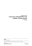
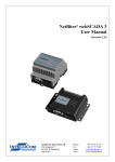
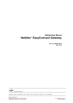
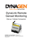
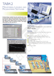
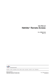
compatible
Installation Guide
Netbiter DC Power Monitor
1 - Preparations
2 - Mounting
Mount the DC Power Monitor in a free
space on a DIN rail.
Check package contents:
• 1 x DC Power Monitor
• 1 x Hall sensor, 2m cable
• 1 x Temperature sensor
• 1 x Installation Guide
Pull down on release
catch to mount.
3 - Mount Hall Sensor
3a
3b
Mount the hall sensor on the power wire of
the load to be measured. Observe the sensor
orientation. In the example here, the sensor vane should point towards the load, and
away from the power source or rectifier. Use
a cable strap to fix the sensor in place.
At the other end of the cable, insert the
green push-connector into the socket to the
right on the underside of the Netbiter DC
Power Monitor, as shown here.
4 - Connect Temp Sensor
4a
This example shows a load with negative
earth. To measure a load with positive
earth, the sensor must be mounted the
other way round.
Mount the temperature
sensor in the required
location (not shown
here).
+24 VDC
LOAD
4b
Rectifier or
Power Source
0 VDC
At the other end of the cable, insert the
green push-connector into the socket
to the left on the underside of the
Netbiter DC Power Monitor, as shown
here.
5 - Voltage Measurement
5a
To set up voltage measurement, connect
a 2-wire cable to the site equipment to be
measured (not shown here).
5b
Using the slotted screwdriver,
connect the other end of the
2-wire cable to the grey plug
connection on the Netbiter DC
Power Monitor, paying close
attention to the +/─ poles.
Important! The voltage connection must be
fused (max 10A) using an inline fuse holder.
Continued overleaf ....
Doc ID: SP1570
Rev: 1.00
compatible
Installation Guide
Netbiter DC Power Monitor
6 - Modbus & Power
Connectors for the 24 VDC power supply and
Modbus are located on the top of the Netbiter DC Power Monitor.
For further information, see also:
Netbiter EasyConnect User Manual
6a
Connect Modbus wire A (black) to
Pin 1 of the Modbus connector.
6b
Connect Modbus wire B (white) to
Pin 2 (middle pin) of the Modbus
connector.
6c
Connect 0V to the (─) terminal of
the power supply connector.
6d
Connect +24V to the (+) terminal of
the power supply connector.
Modbus
Power
7 - Modbus ID Setting
The selector screw on the front of
the unit provides quick setting of
15 different Modbus ID’s. See the
table to the right.
Any other Modbus ID must be set
from software. Set this screw to
0 (= Modbus ID 1 by default) and
contact HMS support for further
information.
Selector
Position
Modbus ID
0
Modus ID 1 (or other ID via software)
1
Modbus ID 31
2
Modbus ID 32
3
Modbus ID 33
4
Modbus ID 34
5
Modbus ID 35
6
Modbus ID 36
...
...
15
Modbus ID 45
All other device settings are available at Netbiter Argos, after the DC Power Monitor has been added to a user account
using a device template or device profile. Please see the Netbiter Argos Administration Manual for further details.
Technical Specifications
Modbus Address
Description
1
Measured current
2
Measured voltage
3
Measured watts
10
Temperature
20
Total Wh
22
Total Wh Incoming
24
Total Wh Outgoing
26
Delta In/Out Wh
30
Alarm
52
Overconsumption time factor
53
OC1 Power setting
54
OC2 Power setting
Doc ID: SP1570
Time constant in seconds for overconsumption alarms.
Allowed settings: 60,120,180,240,300,600,900,1800,3600
Over-consumption alarm 1 will be triggered when the average
consumed energy exceeds this level within the time period
specified in Overconsumption Time Factor.
Over-consumption alarm 2 will be triggered when the average
overcharging energy exceeds this level within the time period
specified in Overconsumption Time Factor.
Rev: 1.00