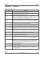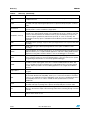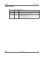
1
UM0406
User manual
STice advanced emulation system
for ST microcontrollers
Introduction
Thank you for choosing STMicroelectronics for your microcontroller application.
The STice is the advanced in-circuit emulation system from STMicroelectronics. Its
advanced debugging features in emulation configuration are complemented by an additional
in-circuit programming/debugging configuration, code coverage and profiling, extensive
trace capabilities and configurable advanced breakpoints, to make it the ideal tool for startto-finish support of microcontroller application development.
The STice is a modular emulation system made up of a main emulation board (MEB) that
provides interface and emulation resources common to all emulated MCU families and a
STice (TEB) that provides the emulation resources for a specific family of microcontrollers. It
may also include a peripheral emulation board (PEB) that provides emulation resources
specific to an emulated peripheral for a microcontroller family.
The STice includes all the emulation boards that you need to emulate in real time any
microcontroller in a given family, while the systems’ modularity provides unprecedented
capability to adapt the STice to emulate new microcontroller families.
Table 1.
Device summary
Part number(1)
Contents
STice
CB-STice
STice emulation system
CF/Stice_Connect
CB-CF/FPxxx
Connection flex
AD/Stice_Connect
CB-AD/xxxxx-xxx
CB-AD-ICD/ICP
Connection adapter for target device package or SWIM connector
AS/Stice_Connect
CB-AS/xxxxxx
Adapter socket
1. Part numbers with the CB prefix are now obsolete.
November 2010
Doc ID 13332 Rev 3
1/26
www.st.com
Contents
UM0406
Contents
1
2
3
4
Introduction . . . . . . . . . . . . . . . . . . . . . . . . . . . . . . . . . . . . . . . . . . . . . . . . 6
1.1
STice in emulation configuration . . . . . . . . . . . . . . . . . . . . . . . . . . . . . . . . 6
1.2
STice in in-circuit debugging/programming configuration . . . . . . . . . . . . . . 7
1.3
About the user manuals . . . . . . . . . . . . . . . . . . . . . . . . . . . . . . . . . . . . . . . 7
Getting started . . . . . . . . . . . . . . . . . . . . . . . . . . . . . . . . . . . . . . . . . . . . . . 8
2.1
Delivery check list . . . . . . . . . . . . . . . . . . . . . . . . . . . . . . . . . . . . . . . . . . . . 8
2.2
Quick setup for emulation configuration . . . . . . . . . . . . . . . . . . . . . . . . . . 10
2.3
Quick setup for in-circuit programming/debugging . . . . . . . . . . . . . . . . . . 11
Emulation configuration . . . . . . . . . . . . . . . . . . . . . . . . . . . . . . . . . . . . . 12
3.1
Supported emulation features . . . . . . . . . . . . . . . . . . . . . . . . . . . . . . . . . 12
3.2
Emulator characteristics . . . . . . . . . . . . . . . . . . . . . . . . . . . . . . . . . . . . . . 13
3.2.1
Physical characteristics . . . . . . . . . . . . . . . . . . . . . . . . . . . . . . . . . . . . . 13
3.2.2
Power supply . . . . . . . . . . . . . . . . . . . . . . . . . . . . . . . . . . . . . . . . . . . . . 15
3.2.3
Output and input triggers . . . . . . . . . . . . . . . . . . . . . . . . . . . . . . . . . . . . 15
3.2.4
Analyzer input connector . . . . . . . . . . . . . . . . . . . . . . . . . . . . . . . . . . . . 16
3.2.5
Application power supply follower . . . . . . . . . . . . . . . . . . . . . . . . . . . . . 16
3.3
Automatic firmware updates . . . . . . . . . . . . . . . . . . . . . . . . . . . . . . . . . . . 17
3.4
Emulator functional limitations and discrepancies . . . . . . . . . . . . . . . . . . 17
3.4.1
Voltage limitation for I2C peripheral . . . . . . . . . . . . . . . . . . . . . . . . . . . . 17
3.4.2
Limitations and discrepancies for specific MCUs or families of MCUs . 17
In-circuit programming/debugging configuration . . . . . . . . . . . . . . . . 18
4.1
Setting up the system for in-circuit programming/debugging . . . . . . . . . . 18
4.2
SWIM connection for in-circuit programming/debugging . . . . . . . . . . . . . 19
Appendix A EMC conformity and safety requirements. . . . . . . . . . . . . . . . . . . . 20
Appendix B Product support . . . . . . . . . . . . . . . . . . . . . . . . . . . . . . . . . . . . . . . . . 21
2/26
B.1
Getting assistance. . . . . . . . . . . . . . . . . . . . . . . . . . . . . . . . . . . . . . . . . . . 21
B.2
Software updates . . . . . . . . . . . . . . . . . . . . . . . . . . . . . . . . . . . . . . . . . . . 21
B.3
Hardware spare parts . . . . . . . . . . . . . . . . . . . . . . . . . . . . . . . . . . . . . . . . 21
Doc ID 13332 Rev 3
UM0406
Contents
B.4
Sockets . . . . . . . . . . . . . . . . . . . . . . . . . . . . . . . . . . . . . . . . . . . . . . . . . . . 21
B.5
Connectors . . . . . . . . . . . . . . . . . . . . . . . . . . . . . . . . . . . . . . . . . . . . . . . . 21
B.6
Getting prepared before you call . . . . . . . . . . . . . . . . . . . . . . . . . . . . . . . . 22
Appendix C Glossary . . . . . . . . . . . . . . . . . . . . . . . . . . . . . . . . . . . . . . . . . . . . . . . 23
Revision history . . . . . . . . . . . . . . . . . . . . . . . . . . . . . . . . . . . . . . . . . . . . . . . . . . . . 25
Doc ID 13332 Rev 3
3/26
List of tables
UM0406
List of tables
Table 1.
Table 2.
Table 3.
Table 4.
Table 5.
Table 6.
Table 7.
4/26
Device summary . . . . . . . . . . . . . . . . . . . . . . . . . . . . . . . . . . . . . . . . . . . . . . . . . . . . . . . . . . 1
Parts delivered with the STice (not to scale) . . . . . . . . . . . . . . . . . . . . . . . . . . . . . . . . . . . . 8
AD-ICD/ICP parts to be ordered separately (not to scale) . . . . . . . . . . . . . . . . . . . . . . . . . . 9
Correspondence between analyzer input pin and wiring . . . . . . . . . . . . . . . . . . . . . . . . . . 16
SWIM signals . . . . . . . . . . . . . . . . . . . . . . . . . . . . . . . . . . . . . . . . . . . . . . . . . . . . . . . . . . . 19
Glossary . . . . . . . . . . . . . . . . . . . . . . . . . . . . . . . . . . . . . . . . . . . . . . . . . . . . . . . . . . . . . . . 23
Document revision history . . . . . . . . . . . . . . . . . . . . . . . . . . . . . . . . . . . . . . . . . . . . . . . . . 25
Doc ID 13332 Rev 3
UM0406
List of figures
List of figures
Figure 1.
Figure 2.
Figure 3.
Figure 4.
Figure 5.
Figure 6.
Figure 7.
Figure 8.
Figure 9.
Figure 10.
Figure 11.
Figure 12.
Figure 13.
STice in emulation configuration. . . . . . . . . . . . . . . . . . . . . . . . . . . . . . . . . . . . . . . . . . . . . . 6
In-circuit programming and debugging configuration . . . . . . . . . . . . . . . . . . . . . . . . . . . . . . 7
Connection for emulation . . . . . . . . . . . . . . . . . . . . . . . . . . . . . . . . . . . . . . . . . . . . . . . . . . 10
Connection for ICD/ICP . . . . . . . . . . . . . . . . . . . . . . . . . . . . . . . . . . . . . . . . . . . . . . . . . . . 11
STice . . . . . . . . . . . . . . . . . . . . . . . . . . . . . . . . . . . . . . . . . . . . . . . . . . . . . . . . . . . . . . . . . 13
Left side panel . . . . . . . . . . . . . . . . . . . . . . . . . . . . . . . . . . . . . . . . . . . . . . . . . . . . . . . . . . 13
Right side panel . . . . . . . . . . . . . . . . . . . . . . . . . . . . . . . . . . . . . . . . . . . . . . . . . . . . . . . . . 14
Front panel . . . . . . . . . . . . . . . . . . . . . . . . . . . . . . . . . . . . . . . . . . . . . . . . . . . . . . . . . . . . . 14
Back panel . . . . . . . . . . . . . . . . . . . . . . . . . . . . . . . . . . . . . . . . . . . . . . . . . . . . . . . . . . . . . 14
Output trigger action modes . . . . . . . . . . . . . . . . . . . . . . . . . . . . . . . . . . . . . . . . . . . . . . . . 15
Analyzer probe input connections (front view) . . . . . . . . . . . . . . . . . . . . . . . . . . . . . . . . . . 16
In-circuit programming/debugging configuration. . . . . . . . . . . . . . . . . . . . . . . . . . . . . . . . . 18
SWIM connections on application board . . . . . . . . . . . . . . . . . . . . . . . . . . . . . . . . . . . . . . 19
Doc ID 13332 Rev 3
5/26
Introduction
UM0406
1
Introduction
1.1
STice in emulation configuration
In emulation configuration, the STice connects to your PC through a USB interface, and to
your application board in place of your target microcontroller using:
●
Connection flex (CF/Stice_Connect) – flexible cable (60 or 120 pins depending on the
target MCU) that relays signals from the STice to your application board.
●
Connection adapter (AD/Stice_Connect) – adapts the connection flex to the target
microcontroller footprint or the SWIM connector on your application board.
●
Adapter socket (AS/Stice_Connect) – socket that solders to your application board in
place of your MCU and receives the connection adapter.
These accessories are not included with the STice emulation system. To determine exactly
what you need to order for any supported microcontroller, refer to the online product selector
on the microcontroller support web site on www.st.com.
Figure 1.
STice in emulation configuration
Free ST toolset
STVD and STVP running on your PC drive STice
1. STice
includes all emulation resources,
MEB, TEB, and PEB
1
2
3
2. CF/Stice_Connect
Connection flex to connect to
application board
3. AD/Stice_Connect
Connection adapter to adapt
connection cable to MCU
4
4. AS/Stice_Connect
Adapter socket on application board
to plug in emulator in place of MCU
6/26
Doc ID 13332 Rev 3
UM0406
1.2
Introduction
STice in in-circuit debugging/programming configuration
In the in-circuit debugging/programming configuration, STice allows you to program your
application to your microcontroller and debug the application while it runs on the MCU on
your application board. Using STice, you can in-circuit program and debug a wide range of
microcontrollers. It supports the single wire interface module (SWIM) protocol for STM8.
In both the emulation and the in-circuit programming/debugging configuration, STice is
driven by the ST Visual Develop (STVD) integrated development environment running on
your host PC, which provides total control of advanced application building, debugging and
programming features from a single easy-to-use interface.
To use STice in ICD/ICP configuration, you need to buy the AD-ICD/ICP adapter kit (see
Table 3 on page 9).
Figure 2.
In-circuit programming and debugging configuration
1. ICD/ICP flat cable connects STice to MCU
via ICD/ICP connector on application board.
1
2
2. AD/Stice_Connect: ICD/ICP
connector relayed to MCU (SWIM
protocol for STM8)
3
1.3
3. ST microcontroller on
application board
About the user manuals
This manual helps you set up your emulator and connect it to your PC. It contains:
●
Quick setup instructions for the emulation and the in-circuit programming/debugging
configurations
●
A detailed description of product features
For information about other hardware and the software intended for use with your emulator,
refer to the following documents:
●
STice Connection Accessories User Guide – for instructions regarding the connection
accessories for connecting your emulator to your application board
●
ST Visual Develop (STVD) on-line help – building and debugging your application
●
ST Visual Programmer (STVP) on-line help – programming your application to your
microcontroller
●
Microcontroller Datasheet – for microcontroller specific information
Doc ID 13332 Rev 3
7/26
Getting started
2
UM0406
Getting started
Your STice can be configured for emulation, as well as in-circuit debugging and
programming of your microcontroller. To help you get started, the following sections provide:
2.1
●
Section 2.1 – a checklist of components included with your emulator
●
Section 2.2 – quick set up instructions for the emulation configuration
●
Section 2.3 – quick set up instructions for the in-circuit programming/debugging
configuration
Delivery check list
Your STice emulation system comes with (refer to Table 2):
1.
STice main unit containing the main emulation board and target emulation board. It will
also contain a peripheral emulation board if required for your microcontroller.
2.
DC power supply for your emulator.
3.
Three trigger cables.
4.
10-wire, analyzer-input cable.
5.
USB cable for emulator-PC connection (mini USB2) standard A to mini-B plug.
6.
Microcontroller Development Tools CD-ROM: all the software you need to run STice,
including STVD integrated development environment + STVP programming interface.
Table 2.
Parts delivered with the STice (not to scale)
(1)
(2)
(3)
(4)
x3
(5)
8/26
Doc ID 13332 Rev 3
UM0406
Getting started
The following accessories are provided in the AD-ICD/ICP kit (ICD adapter for the STice)
which must be ordered separately (refer to Table 3):
1.
Flat cable for SWIM programming/debugging for an STM8 microcontroller (CA112,
ERNI reference 839032).
2.
30 cm 10-wire HE10 flat cable (CA058).
3.
Connectors for SWIM cable: (a) connection board for connecting to the STice (DB722),
and (b) ERNI connector (ERNI reference 214017) for connecting to application board.
Table 3.
AD-ICD/ICP parts to be ordered separately (not to scale)
(1)
(2
CA112
CA058
(3a)
(3b)
DB722
214017
x5
The following connection accessories are also ordered separately.
●
Connection flex (CF/Stice_Connect)
●
Connection adapter (AD/Stice_Connect)
●
Adapter socket (AS/Stice_Connect)
The online product selector on the microcontroller support site on www.st.com indicates
exactly what to order for your MCU.
Doc ID 13332 Rev 3
9/26
Getting started
2.2
UM0406
Quick setup for emulation configuration
Figure 3.
Connection for emulation
1
4
2
5
3
6
Caution:
10/26
1.
Install STVD on your host PC from the provided CD-ROM.
2.
Check the STice power switch is off, then connect the power supply.
3.
Connect the USB cable to your STice and to your host PC. Your PC automatically
identifies the new hardware when the STice is powered on.
4.
Plug the connection flex into the target port on your STice and into the connection
adapter.
5.
Plug the connection adapter into the adapter socket on your application board in place
of your microcontroller.
6.
Connect your application board’s power supply.
7.
Power up your STice then your application board.
Never have your application board powered on while the STice is powered off. This can
cause serious damage to the STice.
Doc ID 13332 Rev 3
UM0406
2.3
Getting started
Quick setup for in-circuit programming/debugging
Figure 4.
Connection for ICD/ICP
STice right panel
1
/ICP
4
2
3
5
1.
Install STVD on your host PC from the provided CD-ROM.
2.
Check the STice power switch is off, then connect the power supply.
3.
Connect the USB cable to STice and to your host PC. Your PC automatically identifies
the new hardware when the STice is powered on.
4.
For an STM8 microcontroller using the SWIM protocol:
a)
Connect the SWIM connector board to the STice ICD/ICP port.
b)
Connect the SWIM cable to the SWIM connector board.
c)
Connect the SWIM cable to the ERNI connector on the application board where
your microcontroller is installed. Information about the SWIM connection for
ICD/ICP is provided in Section 4.2 on page 19.
5.
Connect your application board’s power supply.
6.
Power up your emulator, then your application board.
Doc ID 13332 Rev 3
11/26
Emulation configuration
3
UM0406
Emulation configuration
In the emulation configuration, STice provides you with a full range of emulation features to
make debugging and fine tuning your application fast and easy. The following sections
provide information about the emulation configuration, including descriptions of:
3.1
12/26
●
Section 3.1 – supported emulation features
●
Section 3.2 – emulator characteristics
●
Section 3.4 – firmware updating
●
Section 3.4 – product limitations and discrepancies
Supported emulation features
●
Application profiling for execution time or number of executions at instruction, source
code or function level.
●
Coverage analysis on code (at instruction, source code and function levels) or data (for
memory locations or variables) for the entire memory space.
●
Advanced breakpoints based on a 4-level logical sequencer that allows you to
perform specific actions upon the occurrence of an event or series of events. Advanced
breakpoint functionality provides flexibility of use, permits simple or multi-level
breakpoint conditions, control of trace recording and triggering of output signals.
●
Full access to entire microcontroller memory. Read/write privileges on the entire data
memory space. The granularity of memory mapping is 1 byte.
●
128K x 288-bit real-time trace (address, data and control buses).
●
Read/write on the fly feature allows you to non-intrusively read or write to the entire
data memory (except hardware registers) while executing your application.
●
9 external input triggers, which are recorded in the trace and can be used as signal
events in the advanced breakpoints. Input triggers include:
–
An input trigger via SUB-click connector
–
8 input triggers on analyzer input
●
2 output triggers via SUB-click connectors.
●
Programmable internal CPU clock with frequency up to 50 MHz, depending on your
microcontroller (refer to your microcontroller’s datasheet).
●
Easily upgradable – STice PLDs and firmware are updated automatically by STVD.
●
1.65 to 5.5 V operating voltage, depending on your microcontroller (See Section 3.2.5:
Application power supply follower on page 16).
●
USB 2.0 connection to the host PC supporting high-speed data transmission.
Doc ID 13332 Rev 3
UM0406
3.2
Emulation configuration
Emulator characteristics
The STice is a common hardware target interface and emulator for a range of STM8
microcontrollers. It provides the connection ports (USB, emulator to target, triggers,
analyzer input, etc.) and contains all active communication and emulation resources. The
following sections provide a description of the emulator features.
Figure 5.
STice
Left panel
Back panel
Target connection port for
60- or 120-pin connection
flex
Front panel
Right panel
The target connection port on top of the STice connects to the connection flex, which relays
the emulator to your application board.
The modularity of the STice allows upgrades in order to support new microcontroller
families. More information about available target emulation and peripheral emulations
boards is available on the microcontroller product selector.
3.2.1
Physical characteristics
Left panel
●
Power supply connector
●
On/off switch
●
Power LED
●
USB connector
Figure 6.
Left side panel
Doc ID 13332 Rev 3
13/26
Emulation configuration
UM0406
Right panel
●
Three status LEDs
–
Reset (Red) indicates that the chip is being reset.
–
Wait (Yellow) indicates that emulator is in halt or wait for interrupt mode.
–
Run (Green) indicates that the application is running
●
10-pin in-circuit programming/debugging connector (type HE10)
●
Two output triggers (see Output and input triggers)
●
Input trigger (see Output and input triggers)
Figure 7.
Right side panel
/ICP
Front panel
●
10-pin probe analyzer input connector (see Section 3.2.4 on page 16)
●
Test connector (reserved)
Back panel
●
External link connector (reserved)
●
Sliding door to access mode switch (reserved). Switch must be in Emul position.
Figure 8.
Note:
Do not use the TEST connector on the front panel for in-circuit debugging. The connector for
ICD is located on the right panel, as shown in Figure 9.
Figure 9.
14/26
Front panel
Back panel
Doc ID 13332 Rev 3
UM0406
3.2.2
Emulation configuration
Power supply
The emulator power supply connects to the power supply connector on the left panel of the
emulator (see Figure 6). The provided universal power supply includes three
interchangeable plugs and has the following electrical characteristics:
3.2.3
AC voltage:
110 V to 240 V
Frequency:
47 to 63 Hz
Output and input triggers
Your emulator has two output triggers (OUT1, OUT2), and one input trigger (IN), which are
available via SUB-click connectors located on the right panel (see Figure 7). Both input and
output signals are at TTL level.
Advanced breakpoints in STVD allow you to define an event based on input signals and
program signals to the output triggers.
The following trigger output modes (schematically represented in Figure 10) are supported:
●
output a pulse – where a signal of value 1 is sent during exactly one CPU cycle.
●
toggle – where the signal value is changed from 0 to 1 or from 1 to 0.
●
set the output high – where the output signal is set equal to 1.
●
set the output low – where the output signal is set equal to 0.
Several examples of how to program advanced breakpoints to control the sending of signals
to the output triggers are given in the STVD online help and user manual.
Figure 10. Output trigger action modes
period of time between event provoking pulse action
Pulse output trigger
pulse lasting one processor cycle
2nd toggle action
4th toggle action
6th toggle action
Toggle output trigger
1st toggle action
3rd toggle action
set output low
5th toggle action
set output low
Set output high/low
set output high
set output low
(no action as output already low)
Doc ID 13332 Rev 3
set output high
15/26
Emulation configuration
3.2.4
UM0406
Analyzer input connector
An analyzer input connector is located on the emulator front panel (see Figure 8). The
analyzer input connector allows you to use 8 external input signals (TTL level).
The connector has ten pins—two ground pins (pin 9 and pin 10) and eight input signal pins
(1-8 ), as shown in Figure 11.
Figure 11. Analyzer probe input connections (front view)
Pin 2
Pin 1
4
6
8
3
5
7
Pin 10
Pin 9
A specially adapted 10-wire cable is included to connect your application or an external
device (such as an oscilloscope or multi-meter) to these inlets. Each wire is color-coded as
summarized in Table 4.
Table 4.
3.2.5
Correspondence between analyzer input pin and wiring
Analyzer input pin
Signal
Wire color
1
Input 1
Red
2
Input 0
Brown
3
Input 3
Yellow
4
Input 2
Orange
5
Input 5
Blue
6
Input 4
Green
7
Input 7
Grey
8
Input 6
Purple
9
GND
Black
10
GND
Black
Application power supply follower
Your emulator is equipped with an automatic power supply follower, which converts internal
emulation voltage to the voltage of the application. The application voltage must be within
the range supported by the emulator.
The emulator’s internal power supply regulator supports a VDD voltage up to 5.5 V, and
down to 1.65 V. The lower limit may be higher as it depends on the microcontroller that you
are emulating. For more information about the supported VDD range for your microcontroller,
refer to your microcontroller datasheet.
16/26
Doc ID 13332 Rev 3
UM0406
3.3
Emulation configuration
Automatic firmware updates
The STice is designed so that its firmware can be updated automatically. Firmware may
require updating if you have changed the target emulation board (TEB) or if you have
updated your version of STVD. The update is done automatically if you start a debugging
session and STVD detects an old firmware version. For more information, refer to the STVD
online help.
3.4
Emulator functional limitations and discrepancies
3.4.1
Voltage limitation for I2C peripheral
For all supported microcontrollers, if the I2C peripheral is used, you must limit the pull-up
resistor to 1.5 kOhms.
3.4.2
Limitations and discrepancies for specific MCUs or families of MCUs
Specific MCUs or families of MCUs may be subject to emulation limitations or discrepancies.
You will find information about these specific limitations in the STVD Discrepancies window.
For more information refer to the STVD online help.
Doc ID 13332 Rev 3
17/26
In-circuit programming/debugging configuration
4
UM0406
In-circuit programming/debugging configuration
In the in-circuit programming (ICP) / in-circuit debugging (ICD) configuration, STice provides
the capability to program your application to your microcontroller and to debug your
application as it runs on the microcontroller on your application board. The following
sections provide information about:
4.1
●
Section 4.1 – Setting up the STice to operate in ICD/ICP configuration
●
Section 4.2 – SWIM connection for ICD/ICP of an STM8 microcontroller
Setting up the system for in-circuit programming/debugging
The STice features an in-circuit programming/debugging (ICD/ICP) port that allows you to
take advantage of the single wire interface module (SWIM) protocol for STM8 to program an
application to the microcontroller on your application board and debug the application while
it runs on the target device.
Figure 12. In-circuit programming/debugging configuration
Right panel
Host PC running
STVD for ICP and ICD, or
STVP for ICP
/ICP
STice features an ICD/ICP port on the right
panel (inset) for ICD/ICP using SWIM
Your microcontroller
USB connection
to the host PC
An ICD/ICP connector is relayed to the STM8
microcontroller and allows the connection of
the flat cable from STice.
During application development, STVD software running on your PC provides an integrated
development environment that allows you to debug your application while it runs on your
microcontroller. For more information about in-circuit debugging with STVD, refer to the
STVD online help provided with your software package.
STVD also provides a microcontroller programming interface that supports in-circuit
programming of STM8, or you can use the ST Visual Programming (STVP) interface, which
provides a full-featured graphical interface for verifying memory sectors, checking the
settings of the option bytes and programming the MCU. For more information about
programming with STVP, refer to the STVP online help.
18/26
Doc ID 13332 Rev 3
UM0406
4.2
In-circuit programming/debugging configuration
SWIM connection for in-circuit programming/debugging
The major advantage of the SWIM protocol for in-circuit debugging (ICD) and programming
(ICP) is that signals are exchanged with the microcontroller on a single pin.
To use the SWIM protocol for ICD/ICP of an STM8 microcontroller, your application
hardware design must include an ICD/ICP connector for SWIM (4-pin ERNI connector). This
connector must be relayed to the microcontroller in accordance with the SWIM protocol if
your application integrates an STM8 microcontroller.
These connection requirements are summarized in Table 5 and in Figure 13.
Table 5.
SWIM signals
STM8 pin name
VDD
SWIM
VSS
NRST
Function
SWIM connector pin
Target voltage sense
pin 1: VAPP
SWIM data
pin 2: ISDATA
Ground voltage
pin 3: GND
Target system reset
pin 4: Reset
The 4-pin flat cable provided for ICD/ICP when using the SWIM protocol is 20 centimeters
long (maximum length). On the application board, the maximum distance allowable between
the MCU and the SWIM connector is 5 centimeters. For further information about SWIM,
refer to your STM8 microcontroller datasheet.
Figure 13. SWIM connections on application board
Doc ID 13332 Rev 3
19/26
EMC conformity and safety requirements
Appendix A
UM0406
EMC conformity and safety requirements
This product respects the EMC requirements of the European guideline 89/336/EEC under
the following conditions:
20/26
●
Any tester, equipment, or tool used at any production step, or for any manipulation of
semiconductor devices, must have its shield connected to ground.
●
All provided ferrites must be attached as described in the hardware installation
instructions of the relevant user manual.
●
The product must be placed on a conductive table top, made of steel or clean
aluminum, grounded through a ground cable. Before every contact with the emulator,
the operator must touch the surface of the grounded worktable just behind the back
panel of the emulator. All manipulation of finished goods must be done at such a
grounded worktable.
●
The worktable must be free of all non-antistatic plastic objects.
●
It is recommended that you wear an antistatic wrist or ankle strap, connected to the
antistatic floor covering or to the grounded equipment.
●
If no antistatic wrist or ankle strap is worn, before each manipulation of the powered-on
tool, you must touch the surface of the grounded worktable just behind the back panel
of the emulator.
●
It is recommended that antistatic gloves or finger coats be worn.
●
It is recommended that nylon clothing be avoided while performing any manipulation of
parts.
Doc ID 13332 Rev 3
UM0406
Product support
Appendix B
Product support
If you experience any problems with this product, or if you need spare parts or repairs,
contact the distributor or the STMicroelectronics sales office where you purchased the
product.
In addition, on the ST microcontrollers support site at www.st.com, you will find a complete
listing of ST sales offices and distributors, as well as documentation, software downloads
and user discussion groups to help you answer questions and stay up to date with our latest
product developments.
B.1
Getting assistance
For more information, application notes, FAQs and software updates for all the ST
microcontroller families, check the CD-ROM or the microcontroller support web site on
www.st.com.
For assistance on all ST microcontroller subjects, or for help using your emulator, refer to the
web site to find the ST sales office closest to you. We’ll be glad to help you.
B.2
Software updates
All our latest software and related documentation are available for download from the ST
microcontrollers support site at www.st.com. For information about firmware and hardware
revisions, call your nearest distributor or ST sales office.
If you are using software from a third-party tool provider, please refer to the third-party for
software product support and downloads.
B.3
Hardware spare parts
Your development tool comes with the hardware you need to set it up, connect it to your PC
and connect to your application. However, some components can be bought separately if
you need additional ones. You can order extra components, such as sockets and adapters,
from STMicroelectronics, from the component manufacturer or from a distributor.
To help you find what you need, a listing of accessories for ST development tools is available
on the ST microcontrollers support site at www.st.com.
B.4
Sockets
Complete documentation and ordering information for P/TQFP sockets from Yamaichi,
Ironwood, CAB, Enplas and Erni are provided at their respective Internet sites.
B.5
Connectors
Complete documentation and ordering information for SAMTEC connectors is provided on
the SAMTEC Internet site.
Doc ID 13332 Rev 3
21/26
Product support
B.6
UM0406
Getting prepared before you call
Collect the following information about the product before contacting ST or your distributor:
22/26
1.
Name of the company where you purchased the product.
2.
Date of purchase.
3.
Order code: Refer to the side your emulator’s box. The order code is similar to
STice-SYS001.
4.
Serial number: The serial number is located on the bottom of the STice box and is also
listed on the Global Reference card provided with the emulator. This number is the
serial number for the MEB.
5.
TEB (target emulation board) hardware and firmware versions: The hardware and
firmware versions can be found by opening an STVD session, entering the debug
context and selecting Help>About from the main menu. The TEB version numbers are
given in the Target box – scroll downwards until you find the TEB version (hardware)
and TEB PLD version (firmware).
6.
Target device: The sales type of the ST microcontroller that you are using in your
application.
Doc ID 13332 Rev 3
UM0406
Glossary
Appendix C
Table 6.
Glossary
Glossary
Term
Definition
Debug module
An microcontroller hardware peripheral that is able to manage instruction stepping,
complex breakpoints and abort for in-circuit debugging.
DIL
Dual in-line. A type of device package with two rows of pins for thru-hole mounting.
Sometimes also called DIP (Dual In-line Package).
EEPROM
Electrically erasable programmable read-only memory. A non-volatile type of memory
that can be erased and reprogrammed by program instructions. Since no special power
supplies or ultra-violet light source is needed, the contents of this kind of memory can be
changed without removing the MCU from the application system.
Footprint
The dimensions of the location of a component on a printed circuit board or in a socket. It
depends on the number of pins, their size, type and positioning. The footprint of each
microcontroller is specified in the datasheet in the section titled Package Mechanical
Data.
I2C
Inter-integrated circuit. A protocol for a bus that can be connected to multiple integrated
circuits and that allows any one of them to initiate data transfer.
ICD
In-circuit debugging. The capability to debug an application on a FLASH device using onchip resources (Debug Module, MTC), made possible by the SWIM or ICC protocol.
ICP
In-circuit programming. The capability to program to microcontroller Flash memory while
the target device is installed on an application board, made possible by the SWIM or ICC
protocol.
LQFP
Low-profile quad flat package. A family of integrated circuit packages for surface
mounted assembly. This type of package has a square, flat shape and pins on all four
sides.
LVD
Low voltage detection. A microcontroller feature that allows you to simulate what occurs
when the MCU detects that the supply voltage is below a given threshold.
MCU
A microcontroller is a complete computer system, including a CPU, memory, a clock
oscillator and I/O on a single integrated circuit.
MEB
Main emulation board. One of three emulation boards that make up the STice. The MEB
contains communication and emulation resources that are common to a microcontroller
family. This board provides the link between the Host PC and the Target Emulation
Board.
OTP
One time programmable. Also referred to as OTPROM (One Time Programmable ReadOnly Memory). A non-volatile type of memory that can be programmed but cannot be
erased. An OTP ROM is an EPROM MCU that is packaged in an opaque plastic
package—it is called a one-time programmable MCU because there is no way to expose
the EPROM to a UV light source.
PC
Program counter. The CPU register that holds the address of the next instruction or
operand that the CPU will use.
PEB
Peripheral emulation board. An optional printed circuit board that connects to a Target
Emulation Board (TEB) and provides emulation resources for certain specialized
microcontroller peripherals. The PEB, like the TEB, allows the connection of the emulator
to your application board.
Doc ID 13332 Rev 3
23/26
Glossary
Table 6.
UM0406
Glossary (continued)
Term
Definition
PLD
Programmable logic device. An integrated circuit that can be programmed to perform
complex functions.
PQFP
Plastic quad flat package. A family of integrated circuit packages for surface mounted
assembly. This type is packaged in plastic, has a square flat shape and pins on all four
sides.
RC network
Resistor-capacitor network. A combination of resistors and capacitors in a circuit that are
typically used to control or minimize voltage spikes.
Read/write on the fly
A feature that allows you to perform a non-intrusive read or write of a variable during
emulation (i.e. while program running). The variable may be 8, 16 or 32 bits in size and
can be located anywhere in the emulation memory (up to 64 kilobytes) except for the
hardware register (peripherals) and internal system (A, X, Y, PC, CC and SP). The
Read/Write on the Fly option is available in both the Memory window and Watch window
of STVD.
SDIP
Shrink dual in-line package. A type of device package with two rows of pins for thru-hole
mounting.
SO
Small outline. A type of device package with two rows of pins for SMD or socket
mounting.
STVD
ST visual develop. A software package know as an Integrated Development Environment
(IDE) that allows you to compile and edit application code and to debug STM8 and ST7
applications using either a built-in simulator, an in-circuit debugger or an emulator.
STVP
ST visual programmer. A software application that allows you to program Flash
microcontrollers using an in-circuit programming (ICP) connection and any ICP capable
programming board, emulator or in-circuit programmer/debugger.
SWIM
Single wire interface module protocol. A device communication protocol that makes it
possible to download programs to the microcontroller’s RAM and execute them. This
protocol enables in-circuit programming and, coupled with the microcontroller’s debug
module, makes it possible to in-circuit debug applications via a single wire hardware
interface.
Target device
The microcontroller that you have chosen for your application and that you will emulate or
program.
TEB
Target emulation board. A printed circuit board with connector pins that, when plugged
into the Main Emulation Board (MEB), allows you to connect the emulation to the MCU
socket on your application board for debugging. It may also have a Peripheral Emulation
Board (PEB) mount on it, in order to emulate certain specialized microcontroller
peripherals.
TQFP
Thin quad flat package. A family of integrated circuit packages for surface mounted
assembly. This type of package has a square, flat shape and pins on all four sides.
TTL
Transistor to transistor logic. A bipolar technology where a transistor output is connected
directly to the transistor input of the next stage, rather than connecting through a resistor
or diode.
User application board
Your printed circuit board, which includes a connector/socket for the ST microcontroller
that you have chosen to use.
24/26
Doc ID 13332 Rev 3
UM0406
Revision history
Revision history
Table 7.
Document revision history
Date
Revision
20-Mar-2008
1
Initial release.
14-May-2010
2
Modified note in Table 1 as CB-xxx parts are now obsolete.
Added Chapter 1 (was previously cover pages).
3
Updated for part numbers that changed:
– AS/xxxxxx became AS/Stice_Connect
– AD/xxxxxx-xxx and AD-ICD/ICP became AD/Stice_Connect
– CF/FPxxx became CF/Stice_Connect
08-Nov-2010
Changes
Doc ID 13332 Rev 3
25/26
UM0406
Please Read Carefully:
Information in this document is provided solely in connection with ST products. STMicroelectronics NV and its subsidiaries (“ST”) reserve the
right to make changes, corrections, modifications or improvements, to this document, and the products and services described herein at any
time, without notice.
All ST products are sold pursuant to ST’s terms and conditions of sale.
Purchasers are solely responsible for the choice, selection and use of the ST products and services described herein, and ST assumes no
liability whatsoever relating to the choice, selection or use of the ST products and services described herein.
No license, express or implied, by estoppel or otherwise, to any intellectual property rights is granted under this document. If any part of this
document refers to any third party products or services it shall not be deemed a license grant by ST for the use of such third party products
or services, or any intellectual property contained therein or considered as a warranty covering the use in any manner whatsoever of such
third party products or services or any intellectual property contained therein.
UNLESS OTHERWISE SET FORTH IN ST’S TERMS AND CONDITIONS OF SALE ST DISCLAIMS ANY EXPRESS OR IMPLIED
WARRANTY WITH RESPECT TO THE USE AND/OR SALE OF ST PRODUCTS INCLUDING WITHOUT LIMITATION IMPLIED
WARRANTIES OF MERCHANTABILITY, FITNESS FOR A PARTICULAR PURPOSE (AND THEIR EQUIVALENTS UNDER THE LAWS
OF ANY JURISDICTION), OR INFRINGEMENT OF ANY PATENT, COPYRIGHT OR OTHER INTELLECTUAL PROPERTY RIGHT.
UNLESS EXPRESSLY APPROVED IN WRITING BY AN AUTHORIZED ST REPRESENTATIVE, ST PRODUCTS ARE NOT
RECOMMENDED, AUTHORIZED OR WARRANTED FOR USE IN MILITARY, AIR CRAFT, SPACE, LIFE SAVING, OR LIFE SUSTAINING
APPLICATIONS, NOR IN PRODUCTS OR SYSTEMS WHERE FAILURE OR MALFUNCTION MAY RESULT IN PERSONAL INJURY,
DEATH, OR SEVERE PROPERTY OR ENVIRONMENTAL DAMAGE. ST PRODUCTS WHICH ARE NOT SPECIFIED AS "AUTOMOTIVE
GRADE" MAY ONLY BE USED IN AUTOMOTIVE APPLICATIONS AT USER’S OWN RISK.
Resale of ST products with provisions different from the statements and/or technical features set forth in this document shall immediately void
any warranty granted by ST for the ST product or service described herein and shall not create or extend in any manner whatsoever, any
liability of ST.
ST and the ST logo are trademarks or registered trademarks of ST in various countries.
Information in this document supersedes and replaces all information previously supplied.
The ST logo is a registered trademark of STMicroelectronics. All other names are the property of their respective owners.
© 2010 STMicroelectronics - All rights reserved
STMicroelectronics group of companies
Australia - Belgium - Brazil - Canada - China - Czech Republic - Finland - France - Germany - Hong Kong - India - Israel - Italy - Japan Malaysia - Malta - Morocco - Philippines - Singapore - Spain - Sweden - Switzerland - United Kingdom - United States of America
www.st.com
26/26
Doc ID 13332 Rev 3