1
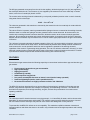
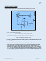
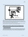
The circuit Nemoto employs for all its internal testing of the NE4-CL2 is shown below:
0. 1μ F
- Vcc
0. 1μ F
R
10kΩ
4
C
8
NE-Cl2
2
6
3
7
54. 9kΩ
1
W
OP97
TH
0. 1μ F
12kΩ
+Vcc
non.
10μ F
- Vcc
0. 1μ F
4
Out put Vol t age
8
10Ω
2
6
3
7
1
OP97
0. 1μ F
10Ω
TH : NTC Ther mi st or
R = 10kΩ B = 3435k
103AT( I shi zuka El ect r oni c Cor p. )
25
+Vcc
Nemoto recognises that the companies who use its gas sensing devices are themselves experts in circuitry
design, often with more expertise than Nemoto in this area. The information given here is hence for initial
guidance only, and Nemoto does not insist that instrument designers reproduce our circuitry guidance precisely.
If the instrument designer deviates from this guidance significantly, however, Nemoto advises that we should be
consulted to ensure that the proposed circuit design will function correctly.
Failure to broadly adhere to the recommended circuitry concept outlined in this document without consultation
with Nemoto may result in the suspension of the warranties which apply to the device.
GENERAL NOTES ON HANDLING, MANUFACTURE AND INSTRUMENT DESIGN
1) Long-term drift of gas sensitivity
All electrochemical gas sensors lose sensitivity over time due to small changes on the surface of the working
electrode, reducing its oxidation capability. To reduce this, the NE4-CL2 uses a newly developed electrode
catalyst that will not deteriorate by more than 10% / year. Typically, these changes are limited to less than 10%
but we recommend that this deterioration should be taken into account when designing application circuits.
NE4-CL2-Manual, Issue 4, Sept 2015
- page 13 of 15 -