1
20
SPECIFICATIONS
20-9
127
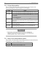
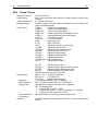
Logic Operation Functions
Number of logic
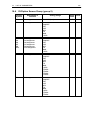
Assignable to 8 points in total: EV1 to EV3 3 points, DO1 to DO5 5 points
DO4 and DO5 are exclusively for timer and counter operation.
TS1 to TS8, and DI1 to DI10, can be assigned individually
Logic operation
inputs
to source 1 and 2
Input logic conversion Input logic conversion possible individually on source 1 and 2 (EV1 to
EV3, DO1 to DO3 output)
1) BUF
By external control input logic
2) INV
Inversion of external control input logic
3) FF
Flip-flop logic operation of external control input
(When a time signal is assigned to a source, flip-flop cannot be set.)
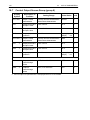
Logic operation output by source 1 and 2 (EV1 to EV3, DO1 to DO3
Logic operation (1)
output)
1) AND
Output by logical product
Output by logical sum
2) OR
3) XOR
Output by exclusive OR
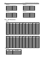
Logic operation (2)
Logic operation Output by source 1 (DO4, DO5 output)
1) Timer operation
OFF, 1 to 5000 seconds
2) Counter operation OFF, 1 to 5000 counts
20-10 Heater Break Alarm (option)
Alarm action
HBA alarm ON when control output is ON and heater break is detected
HLA alarm ON when control output is OFF and heater loop error is
detected
Alarm detection
HBA is detected at heater current ≤ setting current value, when control
output is ON
HLA is detected at heater current ≥ setting current value, when control
output is OFF
Hysteresis at heater Break or loop error detection
0.2 A
Heater current detection by external CT (supplied CT for exclusive
Current detection
use/single phase)
Current detection selection
Selectable from Control Output 1 or Control Output 2 only when control
output is Y or P
Sampling cycle
0.2 seconds (200 msec)
Minimum action confirmation time
0.2 seconds (200 msec) or longer (regardless of whether control output is
ON or OFF)
Current setting
Heater break, heater loop alarm set individually
Setting range
OFF, 0.1 to 50.0 A (OFF = suspension of alarm action)
Setting resolution
0.1 A
Current display
0.0 to 55.0 A
Display accuracy
3% FS (sine wave 50 Hz)
Sampling cycle
0.2 seconds (200 msec)
Minimum action confirmation time
0.2 seconds (200 msec) or longer (regardless of whether control output is
ON or OFF)
Output
Assigned to EVENT, DO output
Output hold
Selectable between Lock mode and Real mode
Isolation
Insulated between CT input and DI input, or CT input and various outputs.
Not insulated between CT input and sensor input, or CT input and the
system.