1
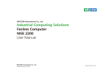
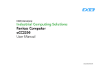
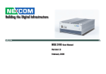
NEXCOM International
Network Security Appliance (NSA) 1041N7
User Manual
NEXCOM International
Published June 2008
www.nexcom.com
Contents
Package Contents
2.4 GAL PIN
. ......................................................................7
2.5 AT / ATX MODE .............................................................................7
2.6 SMBUS .........................................................................................8
2.7 MINI PCI ........................................................................................8
2.8 Reset Button...................................................................................8
2.9 AT MODE PS_ON ............................................................................8
2.10 SMBUS2 ......................................................................................8
2.11 CF / IDE SELECT .........................................................................8
2.12 THERMAL DETECT .....................................................................8
2.13 RTC .............................................................................................9
2.14 KEYBOARD/MOUSE......................................................................9
2.15 GPIO PIN ....................................................................................9
2.16 CONSOLE SELECT . ......................................................................9
2.17 Software Reset.............................................................................9
2.18 IDE POWER CON (J1) ...................................................................9
2.19 VGA (CN1).................................................................................10
2.20 SATA (CN4 , CN6 )
. ........................................................10
2.21 IDE CON (CN5)...........................................................................10
2.22 Main power Con (CON1) . ......................................................11
2.23 MINI-PCI SLOT (CN3)..................................................................11
2.24 Connector location: LAN2..........................................................12
2.25 FAN ( FAN1 , FAN2 , FAN3 , FAN4 ) ..........................................12
2.26 Connector location: LAN1..........................................................13
2.27 COM PORT (CN8)
..................................................13
2.28 Connector location: USB1...........................................................13
2.29 Parallel Port Connector...............................................................13
Preface
Copyright .............................................................................................. vi
Disclaimer .............................................................................................. vi
Acknowledgements ............................................................................... vi
Regulatory Compliance Statements . ...................................................... vi
Safety Information .................................................................................vii
Global Service Contact Information.........................................................vii
Chapter 1: Introducing NSA 1041N7
Overview of NSA 1041N7........................................................................1
Key Features............................................................................................1
Front and Rear Panels..............................................................................1
Hardware Specifications...........................................................................1
Chapter 2: Jumpers and Connectors
Before You Begin ....................................................................................4
Precautions .............................................................................................4
Jumper Settings.......................................................................................5
Locations of Jumpers and Connectors......................................................6
Pin Definitions..........................................................................................7
2.1 Lan Link Act LED . ..........................................................................7
2.2 Lan Link Act LED.............................................................................7
2.3 Power Button.................................................................................7
Copyright © 2008 NEXCOM International Co., Ltd. All Rights Reserved.
ii
NSB1041N7 User Manual
Contents
Boot Up NumLock Status.....................................................................37
Security Option....................................................................................37
Console Redirection.............................................................................37
Baud Rate............................................................................................37
Agent wait time(min)...........................................................................38
Agent after boot.................................................................................38
Advanced Chipset Features....................................................................38
System BIOS Cacheable.......................................................................38
Video RAM Cacheable.........................................................................38
Power Supply Type...............................................................................38
VGA Share Memory Size......................................................................38
Integrated Peripherals............................................................................39
VIA OnChip IDE Device .......................................................................39
OnChip USB Controller........................................................................39
OnChip EHCI Controller.......................................................................39
USB Emulation.....................................................................................39
USB Keyboard Support........................................................................39
USB Mouse Support............................................................................39
Onboard LAN Boot ROM ....................................................................39
Onboard Serial Port 1 / Serial Port 2.....................................................39
UART Mode Select . ............................................................................39
RxD , TxD Active .................................................................................40
UR2 Duplex Mode ..............................................................................40
Onboard Parallel Port . ........................................................................40
Bypass mode after PWR-ON.................................................................40
Bypass mode after PWR-OFF................................................................40
Power Management Setup.....................................................................41
PWRON After Power-Fail......................................................................41
Wake Up On Lan.................................................................................41
Modem Ring Resume..........................................................................41
ACPI Function . ...................................................................................41
Power Management Option................................................................41
2.30 CF (Compact Flash) Slot (IDE1)....................................................14
2.31 System Monitor / GPIO / PCI Routing Description.........................15
Chapter 3: Installing Modules
Removing the Chassis Cover..................................................................16
Installing the Hard Disk..........................................................................18
Installing the PCI Module.......................................................................22
Installing the DIMM...............................................................................25
Installing the CompactFlash Card...........................................................26
Replacing the Chassis Cover...................................................................27
Rackmount bracket kit (Optional)...........................................................28
Chapter 4: Configuring the BIOS Settings
About BIOS Setup .................................................................................32
When to Configure the BIOS ................................................................32
Entering Setup ......................................................................................33
BIOS Main Menu ..................................................................................33
Getting Help..........................................................................................34
Using the Control Keys .........................................................................34
Standard CMOS Features.......................................................................35
Date (mm:dd:yy)..................................................................................35
Time (hh:mm:ss)..................................................................................35
IDE Devices..........................................................................................36
IDE Primary/Secondary Master/Slave.....................................................36
Video..................................................................................................36
Halt On...............................................................................................36
Advanced BIOS Features........................................................................37
Hard Disk Boot Priority.........................................................................37
CPU L1 & L2 Cache.............................................................................37
CPU L2 Cache ECC Checking..............................................................37
First/Second/Third Boot Device.............................................................37
Copyright © 2008 NEXCOM International Co., Ltd. All Rights Reserved.
iii
NSA 1041N7 User Manual
Contents
Power OFF state Bypass Control Function.............................................52
Bypass Function Sample Code................................................................52
HDD Power Down...............................................................................41
Suspend Mode....................................................................................42
Video Off Option ................................................................................42
Video Off Method ..............................................................................42
MODEM Use IRQ.................................................................................42
Soft-Off by PWR-BTN...........................................................................42
IRQ/Event Activity Detect.....................................................................42
PnP/PCI Configurations..........................................................................43
Reset Configuration Data....................................................................43
Resources Controlled By......................................................................43
IRQ Resources......................................................................................43
PC Health Status ...................................................................................44
Load Fail-Safe/Optimized Defaults .........................................................44
Set Password ........................................................................................44
Exit Without Saving ..............................................................................45
Appendix A: Watchdog Timer
Watchdog Timer ...................................................................................46
Logical Device 8 (MIDI Port and GPIO Port 5).......................................46
Watchdog Sample Code......................................................................47
Appendix B: GPI/O Programming Guide
JP15.......................................................................................................49
Logical Device 7 (Game Port, MIDI Port, and GPIO Port 1)......................49
GPIO Sample Code ...............................................................................49
Appendix C: Bypass Specifications
Bypass Control Register Map..................................................................51
Bypass Function...................................................................................51
Bypass Control Function......................................................................52
Copyright © 2008 NEXCOM International Co., Ltd. All Rights Reserved.
iv
NSA 1041N7 User Manual
Package Contents
Before continuing, verify that the NSA 1041N7 package that you received is complete. Your NSA 1086N7 package should have all the items listed in the following table.
Item P/N.
Name
Spec.
1
19S01041N00X0
NSA1041N7
1
PCS
2
60177A0108X00
NSA1041N7 QUICK REFERENCE GUIDE REV:A
1
PCS
3
60233PS203X00
EBC563IO PS2 KB/MS CABLE EDI:201061080201-RS
1
PCS
4
6029900037X00
DOW CORNING 340 Silcone Heat Sink Compound(3g)
1
PCS
5
602DCD0129X00
NSA1041N7 CD DRIVER VER:1.0
1
PCS
6
5060900075X00
NSA1086N7 EAR SETS CHYUAN-JYH:L102007-3
79.5x43.5x28mm AL PANTONE 295U
1
PCS
7
60233PW102X00
POWER CABLE EDI:352204040081-RS
SATA 15PIN TO 3022H-04 4PIN PITCH
5.08mm,L:80mm
1
PCS
8
50311F0102X00
ROUND HEAD SCREW LONG FEI:P6#32Tx 1/4/SW7*0.8
W/SPRING+FLAT WASHER P6#32Tx 1/4/
SW7x0.8 NI
4
PCS
9
5043330139X00
EBC500 CF CARD BRACKET
51.6x47x5mm SPCC T=1.0mm NI
1
PCS
10
50311F0100X00
ROUND HEAD SCREW W/SPRING+FLAT WASHER LONG FEI:
P3x6L
P3x6 iso/SW6x0.5 NI
2
PCS
11
60233ATA05X00
NSA2127-CB SATA CABLE VERA TECH
L:250mm
1
PCS
12
6023309082X00
COM TO RJ45 CABLE FOR CISCO EDI:232091081808-RS
COM PORT. DB9 FEMALE TO RJ45 8P8C
L:1800mm
1
PCS
Copyright © 2008 NEXCOM International Co., Ltd. All Rights Reserved.
v
PS2 TO JST 8PIN 2.54mm L:200mm+-10mm
Qty
NSA 1041N7 User Manual
Preface
Copyright
Acknowledgements
This publication, including all photographs, illustrations and software, is
protected under international copyright laws, with all rights reserved. No
part of this manual may be reproduced, copied, translated or transmitted
in any form or by any means without the prior written consent from NEXCOM International Co., Ltd.
The NSA 1041N7 series is a trademark of NEXCOM international CO., LTD.
All other product names mentioned herein are registered trademarks of
their respective owners.
Version 1.0
Copyright 2008
This section provides the FCC compliance statement for Class A devices
and describes how to keep the system CE compliant.
Regulatory Compliance Statements
Disclaimer
Federal Communications Commission (FCC) For Class A Device
The information in this document is subject to change without prior notice
and does not represent commitment from NEXCOM International Co., LTD.
However, users may update their knowledge of any product in use by constantly checking its manual posted on our website: http://www.nexcom.
com. NEXCOM shall not be liable for direct, indirect, special, incidental, or
consequential damages arising out of the use of any product, nor for any
infringements upon the rights of third parties, which may result from such
use. Any implied warranties of merchantability or fitness for any particular
purpose is also disclaimed.
This equipment has been tested and verified to comply with the limits for
a Class A digital device, pursuant to Part 15 of FCC Rules. These limits are
designed to provide reasonable protection against harmful interference
when the equipment is operated in a commercial environment. This equipment generates, uses, and can radiate radio frequency energy and, if not
installed and used in accordance with the instructions, may cause harmful
interference to radio communications. Operation of this equipment in a
residential area (domestic environment) is likely to cause harmful interference, in which case the user will be required to correct the interference
(take adequate measures) at their own expense.
Copyright © 2008 NEXCOM International Co., Ltd. All Rights Reserved.
vi
NSA 1041N7 User Manual
Preface
▪▪ Avoid using the system near water, in direct sunlight, or near a heating
device.
CE Certification
The product(s) described in this manual complies with all applicable European Union (CE) directives if it has a CE marking. For computer systems to
remain CE compliant, only CE-compliant parts may be used. Maintaining
CE compliance also requires proper cable and cabling techniques.
▪▪ The load of the system unit does not solely rely for support from the
rack mounts located on the sides. Firm support from the bottom is
highly necessary in order to provide balance stability.
WARNINGS
Read and adhere to all warnings, cautions, and notices in this guide
and the documentation supplied with the chassis, power supply, and
accessory modules. If the instructions for the chassis and power supply
are inconsistent with these instructions or the instructions for accessory
modules, contact the supplier to find out how you can ensure that your
computer meets safety and regulatory requirements.
Global Service Contact Information
Headquarters
NEXCOM International Co, Ltd.
18F, No. 716, Chung-Cheng Road
Chung-Ho City, Taipei County 235
Taiwan, R.O.C.
Tel: 886-2-8228-0606
Fax: 886-2-8228-0501
Email: [email protected]
CAUTION
Electrostatic discharge (ESD) can damage NSA components. Do the
described procedures only at an ESD workstation. If no such station is
available, you can provide some ESD protection by wearing an antistatic
wrist strap and attaching it to a metal part of the computer chassis.
USA
Safety Information
NEXCOM USA
3758. Spinnaker Court
Fremont, CA 94538, USA
Tel: 1-5 10-656-2248
Fa: 1-51 0.656-21 58
www.nexcom.com
Email: [email protected]
▪▪ Before installing and using the device, note the following precautions:
▪▪ Read all instructions carefully.
▪▪ Do not place the unit on an unstable surface, cart, or stand.
▪▪ Follow all warnings and cautions in this manual.
▪▪ When replacing parts, ensure that your service technician uses parts
specified by the manufacturer.
Copyright © 2008 NEXCOM International Co., Ltd. All Rights Reserved.
vii
NSA 1041N7 User Manual
Preface
France
Japan
NEXCOM France
Z.I. des Amandiers
17, Rue des entrepreneurs
78420 Carrières sur Seine, France
Tel: +33 (0)1 71 51 10 20
Fax: +33 (0)1 71 51 10 21
www.nexcom.com
NEXCOM Japan
1OF, Nakagin-Shiroyama Building
8-16-13. Ginza Chuou-KU
Tokyo 104-0061, Japan
Tel: 81-3-3524-4250
Fax: 81-3-3524-4252
www.nexcom-jp.com
Email: [email protected]
Germany
China
NEXCOM GmbH
Leopoldstraße Business Centre
Leopoldstraße 244
80807 Munich, Germany
Tel: 49-8920-8039275
Fax: 49-8920-8039279
Email: [email protected]
www.nexcom.com
NEXCOM China
Room 301, Block E
Power Creative Building
No. 1 Shangdi East Rd.
Haidian District
Beijing, 100085, China
Tel: 86-1 0-5885-6655
Fax: 86-1 0-5885-1066
www.nexcom.cn
Email: [email protected]
United Kingdom
NEXCOM UK
10 Vincent Avenue,
Crownhill Business Centre
Milton Keynes, Buckinghamshire
MK8 0AB, United Kingdom
Tel: 44-1908-267121
Fax: 44-1908-262042
Email: [email protected]
www.nexcomuk.co.uk
Copyright © 2008 NEXCOM International Co., Ltd. All Rights Reserved.
viii
NSA 1041N7 User Manual
Chapter 1: Introducing NSA 1041N7
Overview of NSA 1041N7
Front and Rear Panels
NSA 1041N7 is member of NEXCOM’s family of superior x86-based network
security appliance platforms. NSA 1041N7 is an ultra-reliable hardware platform with high performance CPU and Gigabit infrastructures.
The following figures show the front and rear panels of the NSA 1041N7.
With enhanced network connectivity and expansion capability, the NSA
1041N7 is the ideal platform for building network security applications (such
as IDS/IPS, anti-virus/anti-spyware/anti-spam and load balancing) intended
for enterprise-classenvironments.
Key Features
NSA 1041N7 provides the following key features:
▪▪ 1U rackmount network platform
▪▪ Compliance and full compatibility with RoHS
▪▪ CPU Onboard – VIA® CPU C7 1.5GHz, 400MHz FSB Processors
▪▪ VIA® CN700 and 8237R+ Chipsets
▪▪ One 240-pin DDR-II DIMM Socket supporting unbuffered non-ECC DDR
533 up to 1GB
▪▪ Supports CompactFlash and SATA/IDE interfaces
Copyright © 2008 NEXCOM International Co., Ltd. All Rights Reserved.
Hardware Specifications
The following are the hardware specifications for NSA 1041N7.
Chassis
▪▪ Model Name: NSC1042N7
▪▪ 1U Rackmount chassis
▪▪ Supports the NSB1041N7 or NSB1042N7 main board
▪▪ Support one SATA 3.5” HDD bay
▪▪ Four RJ45 for GLAN, One RJ45 for RS-232
1
NSA 1041N7 User Manual
Chapter 1: Introducing NSA 1041N7
▪▪ Dimensions: 426mm (W) x 362mm (L) x 44mm (H)
▪▪ Weight: 3.8 kg
▪▪ Wake-on-LAN in LAN 4
▪▪ 4 x RJ45 with LED connector
Motherboard
▪▪ Model Name: NSB1041N7
▪▪ Dimensions: 325mm x 320mm
▪▪ LAN status LED (ACT and LNK)
Board I/O
▪▪ RS-232 (RJ-45 type) connector for console only in front of chassis
▪▪ One 8 pin header for PS/2 Keyboard and Mouse
▪▪ 8 GPIO lines via Header (4 In and 4 Out)
▪▪ 1 x Pin Header for SIO
▪▪ 4 x 3-pin FAN WAFER connector for CPU and Chassis
▪▪ 1 x On Board buzzer
▪▪ 1 x Reset Button (From Programmable GPIO)
▪▪ Pin Header for PIO
▪▪ 1 x CF socket (with cover)
▪▪ 1 x 44-pin IDE connector
▪▪ 2 x SATA connector
▪▪ 1 x Power connector for 3.5" HDD
▪▪ 1 x Mini-PCI socket
▪▪ 1 x Right-angle PCI slot
▪▪ Pin Header(2.54) for LAN/System LED for rear side
Processor
▪▪ CPU onboard
▪▪ Supports CPU Up To C7 1.5GHz
▪▪ 90nm Process Technology
▪▪ 1.5GHz @ 400MHz FSB
▪▪ PowerSaverTM Technology enabled
▪▪ NanoBGA2 footprint
▪▪ 128/128K L1/L2 Cache
Memory
▪▪ One 240-pin DIMM Socket, up to 1GB un-buffered non-ECC DDR-II 533
SDRAM
Chipset
▪▪ VIA® CN700
▪▪ VIA® 8237R+
Input/Output
▪▪ Front I/O
• 1 x Power LED
• 1 x HDD Active LED
• 1 x Bypass LED (Green)
• 3 x GPIO LED (Green/Blue)
• 4 x RJ45 CNN with LED (ACT and LINK) for GLAN(1086N7) / Co-lay
Graphic
▪▪ VIA® CN700 Integrated
▪▪ VGA pin header onboard
Network
▪▪ 4 x Intel 82541PI GbE LAN
▪▪ Bypass: LAN 1 and LAN 2 (Default), Dual-latch type
▪▪ PXE support
Copyright © 2008 NEXCOM International Co., Ltd. All Rights Reserved.
2
NSA 1041N7 User Manual
Chapter 1: Introducing NSA 1041N7
▪▪ Reserved ATX/AT power design
▪▪ 1 x Power connector
1x4 or 1x2 – 2 sets
• 1 x RS-232(RJ-45) connector
• 2 x USB2.0 connector
• 1 x (2x16) LCD Module; Optional Back-light color (green/blue/orange)
• 1 x Software Reset button
▪▪ Rear I/O
• 1 x PCI Expansion
• 1 x Power On/Off switch
Drivers
▪▪ Linux kernel 2.4 and 2.6 above
Manufacture Requirements
▪▪ Built-in ICT testing point and coverage must exceed 95%
▪▪ Minimal hand inserted and no hand soldered parts
Certifications
▪▪ CE/FCC approval Class A
▪▪ 60950 including CA,UL, and CE standards
Expansion Slots
▪▪ 1 x Mini PCI slot
▪▪ 1 x PCI Slot – supports PCI expansion with IO on the rear side; supports
the half-length PCI card.
Operating Temperature
o
o
▪▪ 0 C to 40 C
System Management
▪▪ Monitoring of voltage, 3 x temperature and 4 x fans
▪▪ Watchdog timeout can be programmable by Software from
1 second to 128 seconds
Storage Temperature
o
o
▪▪ -20 C to 85 C
Relative Humidity
▪▪ 10% to 95% non-condensing
RTC
▪▪ On-chip RTC with battery back up
▪▪ 1 x External Li-ion Battery
BIOS
▪▪ Award System BIOS
▪▪ 4M bits flash ROM
Main Board Power Design
▪▪ 180W FlexATX12V PFC Power Supply (150 x 81.5 x 40.5mm),
FSP180-50PLA(N094) (P/N: 7420180006X00)
▪▪ 1 x Onboard ATX connector
Copyright © 2008 NEXCOM International Co., Ltd. All Rights Reserved.
3
NSA 1041N7 User Manual
Chapter 2: Jumpers and Connectors
tronic components. Humid environment tend to have less static electricity than dry environments. A grounding strap is warranted whenever
danger of static electricity exists.
This chapter describes how to set the jumpers on the NSA 1041N7 board.
Note that the following procedures are generic for all NSA 1041N7 series.
Before You Begin
Precautions
• Ensure you have a stable, clean working environment. Dust and dirt can
get into components and cause a malfunction. Use containers to keep
small components separated.
Computer components and electronic circuit boards can be damaged by
discharges of static electricity. Working on the computers that are still connected to a power supply can be extremely dangerous.
• Adequate lighting and proper tools can prevent you from accidentally
damaging the internal components. Most of the procedures that follow
require only a few simple tools, including the following:
Follow the guidelines below to avoid damage to your computer or yourself:
• Always disconnect the unit from the power outlet whenever you are
working inside the case.
• A Philips screwdriver
• A flat-tipped screwdriver
• A set of jewelers Screwdrivers
• A grounding strap
• An anti-static pad
• If possible, wear a grounded wrist strap when you are working inside
the computer case. Alternatively, discharge any static electricity by
touching the bare metal chassis of the unit case, or the bare metal body
of any other grounded appliance.
• Using your fingers can disconnect most of the connections. It is recommended that you do not use needle-nosed pliers to disconnect connections as these can damage the soft metal or plastic parts of the connectors.
• Hold electronic circuit boards (such as the NSA1088E board) by the
edges only. Do not touch the components on the board unless it is necessary to do so. Don’t flex or stress the circuit board.
• Leave all components inside the static-proof packaging that they
shipped with until they are ready for installation.
• Before working on internal components, make sure that the power
is off. Ground yourself before touching any internal components, by
touching a metal object. Static electricity can damage many of the elec-
Copyright © 2008 NEXCOM International Co., Ltd. All Rights Reserved.
4
NSA 1041N7 User Manual
Chapter 2: Jumpers and Connectors
• Use correct screws and do not over tighten screws.
Jumper Settings
A jumper is the simplest kind of electric switch. It consists of two metal
pins and a cap. When setting the jumpers, ensure that the jumper caps are
placed on the correct pins. When the jumper cap is placed on both pins,
the jumper is short. If you remove the jumper cap, or place the jumper
cap on just one pin, the jumper is open.
Refer to the illustrations below for examples of what the 2-pin and 3-pin
jumpers look like when they are short (on) and open (off).
Two-Pin Jumpers: Open (Left) and Short (Right)
Three-Pin Jumpers: Pins 1 and 2 Are Short
Copyright © 2008 NEXCOM International Co., Ltd. All Rights Reserved.
5
NSA 1041N7 User Manual
Chapter 2: Jumpers and Connectors
Locations of Jumpers and Connectors
The following figure identifies the locations of the different jumpers and connectors on the NSA 1041N7 board. Use your PDF viewer’s zoom function to
enhance readability.
Copyright © 2008 NEXCOM International Co., Ltd. All Rights Reserved.
6
NSA 1041N7 User Manual
Chapter 2: Jumpers and Connectors
Pin Definitions
2.3 Power Button
1. Connector location: JP3
2. Connector pin definition
This section provides descriptions and illustrations for the pin definition of
each available jumper, connector, or socket.
2.1 Lan Link Act LED
1. Connector location: JP1
2. Connector pin definition
Pin NO.
Description
SHORT
ENABLE
OPEN
DISABLE
Pin NO.
Description
1-2-5-6
+3.3V
3
ACTLED_C
4
LINK_C
7
ACTLED_D
2.4 GAL PIN
8
LINK_D
1. Connector location: JP4
2. Connector pin definition
2.2 Lan Link Act LED
Pin NO.
Description
1. Connector location: JP2
2. Connector pin definition
1
+3.3V
2
GND
TCK
Pin NO.
Description
3
1-2-5-6
+3.3V
4
TDO
3
ACTLED_A
5
TDI
4
LINK_A
6
TMS
7
ACTLED_B
8
LINK_B
2.5 AT / ATX MODE
1. Connector location: JP5
2. Connector pin definition
Copyright © 2008 NEXCOM International Co., Ltd. All Rights Reserved.
7
NSA 1041N7 User Manual
Chapter 2: Jumpers and Connectors
Pin NO.
Description
2.9 AT MODE PS_ON
1-2
ATX MODE
2-3
AT MODE
1. Connector location: J9
2. Connector pin definition
2.6 SMBUS
1. Connector location: JP6
2. Connector pin definition
Pin NO.
Description
1-2
ATX MODE
2-3
AT MODE
Pin NO.
Description
2.10 SMBUS2
1
SMB_DATA
2
SMB_CLK
1. Connector location: JP10
2. Connector pin definition
3
GND
2.7 MINI PCI
1. Connector location: JP7
2. Connector pin definition
Pin NO.
Description
1
SMB_DATA
2
SMB_CLK
3
GND
Pin NO.
Description
2.11 CF / IDE SELECT
1-2
+3VDAUL
2-3
+3.3V
1. Connector location: JP11
2. Connector pin definition
2.8 Reset Button
1. Connector location: JP8
2. Connector pin definition
Pin NO.
Description
1-2
CF Master
2-3
CF Slave
Pin NO.
Description
2.12 THERMAL DETECT
SHORT
ENABLE
OPEN
DISABLE
1. Connector location: JP12
2. Connector pin definition
Copyright © 2008 NEXCOM International Co., Ltd. All Rights Reserved.
8
NSA 1041N7 User Manual
Chapter 2: Jumpers and Connectors
Pin NO.
Description
Pin NO.
Description
SHORT
ENABLE
1-3-5-7
GPI
OPEN
DISABLE
2-4-6-8
GPO
9-10
GND
2.13 RTC
2.16 CONSOLE SELECT
1. Connector location: JP13
2. Connector pin definition
1. Connector location: JP16
2. Connector pin definition
Pin NO.
Description
1-2
NORMAL
Pin NO.
Description
2-3
CLEAR
1-2
ON
2-3
OFF
2.14 KEYBOARD/MOUSE
2.17 Software Reset
1. Connector location: JP14
2. Connector pin definition
1. Connector location: SW1
2. Connector pin definition
Pin NO.
Description
1,2
5V
Pin NO.
Description
3
KBDATA
SHORT
ENABLE
4
MSDATA
OPEN
DISABLE
5
KBCLK
6
MSCLK
7,8
GND
2.15 GPIO PIN
2
1
J1
1. Connector location: JP15
2. Connector pin definition
Copyright © 2008 NEXCOM International Co., Ltd. All Rights Reserved.
3
4
2.18 IDE POWER CON (J1)
Pin NO.
9
Description
Pin NO.
Description
Pin NO.
Description
NSA 1041N7 User Manual
Chapter 2: Jumpers and Connectors
1
+12V
2,3
GND
4
2.21 IDE CON (CN5)
+5V
2.19 VGA (CN1)
2 x 8 2.0mm Box header
Pin NO.
Description
Pin NO.
Description
Pin NO.
Description
1
VGA_R
2
VGA_G
3
VGA_B
4
NC
5
GND
6
GND
7
GND
8
GND
9
+5V
10
GND
11
NC
12
VGA_
DATA
13
VGA_HSY
14
VGA_VSY
15
VGA_CLK
16
NC
2.20 SATA (CN4 , CN6 )
Pin NO.
Description
Pin NO.
Description
Pin NO.
Description
1
GND
2
STX_P
3
STX_N
4
GND
5
SRX_N
6
SRX_P
7
GND
Copyright © 2008 NEXCOM International Co., Ltd. All Rights Reserved.
10
Pin NO.
Description
Pin NO.
Description
Pin NO.
Description
1
-IDERST
2
GND
3
PDD7
4
PDD8
5
PDD6
6
PDD9
7
PDD5
8
PDD10
9
PDD4
10
PDD11
11
PDD3
12
PDD12
13
PDD2
14
PDD13
15
PDD1
16
PDD14
17
PDD0
18
PDD15
19
GND
20
NC
21
PDDREQ
22
GND
23
-PDIOW
24
GND
25
-PDIOR
26
GND
27
PHDRDY
28
GND
29
PDDACK
30
GND
31
IRQ15
32
NC
33
PDA1
34
DMA66
Detect
35
PDA0
36
PDA2
37
-PCS1
38
-PCS3
39
HD_LED
40
GND
41
VCC5
42
VCC5
43
GND
44
NC
NSA 1041N7 User Manual
Chapter 2: Jumpers and Connectors
2.22 Main power Con (CON1)
13
N/A
14
N/A
Pin NO.
Description
Pin NO.
Description
Pin NO.
Description
15
N/A
16
N/A
17
PCI_IRQ#D
18
VCC5
1,2,11
+3.3V
3,5,7
GND
13,15,16,17
GND
19
VCC3
20
PCI_IRQ#A
4,6,19,20
+5V
8
POWER_
OK
9
5VSB
21
N/A
22
N/A
10
+12V
12
-12V
14
PS_ON
23
GND
24
+3.3VSB OR
+3.3V
25
PCI_CLK0
26
PCI_RST#
27
GND
28
VCC3
29
PCI_REQ#0
30
PCI_GNT#0
31
VCC3
32
GND
33
PCI_AD31
34
PCI_PME#
35
PCI_AD29
36
N/A
37
GND
38
PCI_AD30
39
PCI_AD27
40
VCC3
41
PCI_AD25
42
PCI_AD28
43
N/A
44
PCI_AD26
45
PCI_CBE#3
46
PCI_AD24
47
PCI_AD23
48
PCI_AD19
49
GND
50
GND
51
PCI_AD21
52
PCI_AD22
53
PCI_AD19
54
PCI_AD20
55
GND
56
PCI_PAR
57
PCI_AD17
58
PCI_AD18
2.23 MINI-PCI SLOT (CN3)
Pin NO.
Description
Pin NO.
Description
1
N/A
2
N/A
3
N/A
4
N/A
5
N/A
6
N/A
7
N/A
8
N/A
9
N/A
10
N/A
11
N/A
12
N/A
Copyright © 2008 NEXCOM International Co., Ltd. All Rights Reserved.
11
NSA 1041N7 User Manual
Chapter 2: Jumpers and Connectors
59
PCI_CBE#2
60
PCI_AD16
107
N/A
108
N/A
61
PCI_IRDY#
62
GND
109
N/A
110
N/A
63
VCC3
64
PCI_FRAME#
111
N/A
112
N/A
65
N/A
66
PCI_TRDY#
113
MINI_AGND
114
GND
67
PCI_SERR#
68
PCI_STOP#
115
N/A
116
N/A
69
GND
70
VCC3
117
N/A
118
AUDIO-GND
71
PCI_PERR#
72
PCI_DEVSEL#
119
MINI_AGND
120
MINI_AGND
73
PCI_CBE#1
74
GND
121
N/A
122
MINIZ01
75
PCI_AD14
76
PCI_AD15
123
MINI_VCC5A
124
77
GND
78
PCI_AD13
+3.3VSB OR
+3.3V
79
PCI_AD12
80
PCI_AD11
81
PCI_AD10
82
GND
83
GND
84
PCI_AD9
85
PCI_AD8
86
PCI_CBE#0
87
PCI_AD7
88
VCC3
89
VCC3
90
PCI_AD6
91
PCI_AD5
92
PCI_AD4
93
N/A
94
2.24 Connector location: LAN2
Pin NO.
Description
Pin NO.
Description
Pin NO.
Description
PCI_AD2
1
MDX0+
2
MDX0-
3
MDX1+
MDX2+
5
MDX2-
6
MDX1-
95
PCI_AD3
96
PCI_AD0
4
97
VCC5
98
N/A
7
MDX3+
8
MDX3-
9
LINK_LED
99
PCI_AD1
100
N/A
10
+3.3V
11
ACT_LED
12
+3.3V
101
GND
102
GND
13
GND
14
GND
103
N/A
104
GND
105
N/A
106
N/A
Copyright © 2008 NEXCOM International Co., Ltd. All Rights Reserved.
2.25 FAN ( FAN1 , FAN2 , FAN3 , FAN4 )
12
NSA 1041N7 User Manual
Chapter 2: Jumpers and Connectors
Pin NO.
1
Description
Pin NO.
GND
2
Description
Pin NO.
+12V
3
Description
FAN speed
sense
Pin NO.
Description
Pin NO.
Description
Pin NO.
Description
1
DCD
2
RXD
3
TXD
4
DTR
5
GND
6
DSR
7
RTS
8
CTS
9
RING
10
NC
2.28 Connector location: USB1
2.26 Connector location: LAN1
Pin NO.
Pin NO.
Description
Pin NO.
Description
Description
Pin NO.
Description
Description
Pin NO.
Pin NO.
Description
1
+5V
2
DATA_0-
3
DATA_0+
1
RTS
2
DTR
3
TXD
4
GND
5
+5V
6
DATA_1-
4
GND
5
DCD PIN
6
RXD
7
DATA_1+
8
GND
7
DSR
8
CTS
2.29 Parallel Port Connector
2.27 COM PORT (CN8)
Copyright © 2008 NEXCOM International Co., Ltd. All Rights Reserved.
2 x 13 2.0mm Box header
13
Pin NO.
Description
Pin NO.
Description
1
STB#
2
AFD
3
PD0
4
ERR
5
PD1
6
INIT#
NSA 1041N7 User Manual
Chapter 2: Jumpers and Connectors
7
PD2
8
SLIN
11
GND
12
GND
9
PD3
10
GND
13
VCC5
14
GND
11
PD4
12
GND
15
GND
16
GND
Pin NO.
13
PD5
14
GND
Description
15
PD6
16
GND
17
GND
18
19
17
PD7
18
GND
ADDRESS_2
ADDRESS_1
19
ACK#
20
GND
20
21
DATA0
22
DATA1
21
BUSY
22
GND
ADDRESS_0
23
PE
24
GND
23
DATA2
24
IOCS16#
(NC)
25
CF_CD2#
25
SLCT
26
26
CF_CD1#
27
DATA11
28
DATA12
29
DATA13
30
DATA14
31
DATA15
32
CS1#
33
CF_VS1#
(NC)
34
IOR
35
IOW
36
VCC5
37
IRQ15
38
VCC5
39
CF_CSEL#
40
CF_VS2#
(NC)
41
Reset #
42
IOCHRDY
43
PDDREQ
44
PDDACK
45
HD_LED
46
DMA66
Detect
48
DATA9
49
DATA10
2.30 CF (Compact Flash) Slot (IDE1)
A. Connector location: IDE1
B. Connector pin definition
Pin NO.
Description
Pin NO.
Description
47
DATA8
1
GND
2
DATA3
50
GND
3
DATA4
4
DATA5
5
DATA6
6
DATA7
7
CS0#
8
GND
9
GND
10
GND
Copyright © 2008 NEXCOM International Co., Ltd. All Rights Reserved.
14
NSA 1041N7 User Manual
Chapter 2: Jumpers and Connectors
2.31 System Monitor / GPIO / PCI Routing Description
Monitor IC: W83792G
• Voltage:
OUTPUT
W83697UF pin name
Pin number
TOUT0
GP13
125
TOUT1
GP12
126
GP11
127
GP10
128
ITEM
Pin
TOUT2
1.8V
33
TOUT3
3.3V
34
Vcore
36
5V
32
12V
31
PCI Routing
• Temperature:
Port NO. Chip
Function IDSEL
INT
REQ
GNT
MINI_
PCI
Mini-PCI AD19
Connector
INTA
REQ0
GNT0
1G Ethernet
AD20
INTB
REQ1
GNT1
AD21
INTC
REQ2
GNT2
LAN1
82541PI
ITEM
Pin
LAN2
Reserve for Pin header
40
LAN3
AD22
INTD
REQ3
GNT3
On board thermistor
39
LAN4
AD23
INTA
REQ4
GNT4
CPU temperature
38
PCI
SLOT
AD24
INTB
REQ5
GNT5
PCI
SLOT
GPIO ( Super I/O: W83697UF ).
INPUT
W83697UF pin name
Pin number
TIN0
GP17
121
TIN1
GP16
122
TIN2
GP15
123
TIN3
GP14
124
Copyright © 2008 NEXCOM International Co., Ltd. All Rights Reserved.
15
NSA 1041N7 User Manual
Chapter 3: Installing Modules
2. Slide the cover towards the back.
This chapter provides information on how to install the supported modules, including the CPU, hard disk, DIMM RAM, CompactFlash card, and
PCI module
Removing the Chassis Cover
1. Remove the screws that secure the cover to the chassis.
Copyright © 2008 NEXCOM International Co., Ltd. All Rights Reserved.
16
NSA 1041N7 User Manual
Chapter 3: Installing Modules
3.Lift the cover and remove it from the chassis.
Copyright © 2008 NEXCOM International Co., Ltd. All Rights Reserved.
17
NSA 1041N7 User Manual
Chapter 3: Installing Modules
Installing the Hard Disk
2. Remove the screws that secure the bracket to the motherboard. Set the
screws aside in a safe place; you will need them later.
1. Locate the hard disk drive bracket on the motherboard.
Copyright © 2008 NEXCOM International Co., Ltd. All Rights Reserved.
18
NSA 1041N7 User Manual
Chapter 3: Installing Modules
3. Place the bracket facing up (as shown below) on a flat surface.
Copyright © 2008 NEXCOM International Co., Ltd. All Rights Reserved.
4. Place your 3.5” hard disk inside the bracket.
19
NSA 1041N7 User Manual
Chapter 3: Installing Modules
5. Fasten the bracket onto the hard disk using the screws provided in the
package.
6. Replace the bracket (with the hard disk attached) onto the motherboard.
7. Secure the bracket back onto the motherboard using the screws that
you removed earlier.
Copyright © 2008 NEXCOM International Co., Ltd. All Rights Reserved.
20
NSA 1041N7 User Manual
Chapter 3: Installing Modules
8. Take the SATA/IDE and power connectors that are included in the package, and then connect them to the corresponding slots on the motherboard.
9. Connect the other ends of the SATA/IDE connector and power connector to the corresponding slots on the rear of the hard disk.
You have completed installing the hard disk.
Copyright © 2008 NEXCOM International Co., Ltd. All Rights Reserved.
21
NSA 1041N7 User Manual
Chapter 3: Installing Modules
Installing the PCI Module
2. Remove that screws that secure the PCI bracket to the motherboard.
1. Locate the PCI bracket on the motherboard.
Copyright © 2008 NEXCOM International Co., Ltd. All Rights Reserved.
22
NSA 1041N7 User Manual
Chapter 3: Installing Modules
3. Remove the slot cover on the PCI bracket. Do this by removing the
screw that fastens the cover to the bracket.
Copyright © 2008 NEXCOM International Co., Ltd. All Rights Reserved.
4. Insert the PCI module into the PCI slot on the bracket. Press the module
firmly but gently into the slot and make sure it is seated securely.
23
NSA 1041N7 User Manual
Chapter 3: Installing Modules
5. Fasten the PCI module to the bracket using the screw that you removed
earlier.
6. Replace the bracket (with the PCI module installed) onto the motherboard, and then secure it using the screws that you removed earlier.
You have completed installing the PCI module.
Copyright © 2008 NEXCOM International Co., Ltd. All Rights Reserved.
24
NSA 1041N7 User Manual
Chapter 3: Installing Modules
Installing the DIMM
3. Align the DIMM into the socket so that the notch on the DIMM
matches the break on the socket. Note how the module is keyed to the
socket. This ensures the module can be plugged into the socket one
way only.
1. Locate the DIMM socket on the motherboard.
4. Firmly but gently press the DIMM into the socket until the retaining clips
snap back into place and the DIMM is properly seated.
2. Make sure that the latches or retaining clips are positioned outward.
This indicates that the socket is unlocked.
You have completed installing the DIMM.
Copyright © 2008 NEXCOM International Co., Ltd. All Rights Reserved.
25
NSA 1041N7 User Manual
Chapter 3: Installing Modules
Installing the CompactFlash Card
2. Insert the CF card into the socket with the label facing up.
1. Locate the CompactFlash (CF) card slot on the motherboard.
Copyright © 2008 NEXCOM International Co., Ltd. All Rights Reserved.
26
NSA 1041N7 User Manual
Chapter 3: Installing Modules
Replacing the Chassis Cover
3. Firmly but gently push the CF card into the slot until it is fully seated in
the slot.
1. Replace the chassis cover.
You have completed installing the CF card.
Copyright © 2008 NEXCOM International Co., Ltd. All Rights Reserved.
27
NSA 1041N7 User Manual
Chapter 3: Installing Modules
Rackmount bracket kit (Optional)
2. Secure the chassis cover to the chassis using the six screws you removed
earlier.
The rackmount bracket kit provides a convenient and economical way
to install the server to the rack cabinet.
Attaching the long rack ears
The long rack ears are used to support the server system in a rack
cabinet.
To attach the long rack ears:
1. Prepare the pair of long rack ears and set of twelve (12) screws.
Copyright © 2008 NEXCOM International Co., Ltd. All Rights Reserved.
28
NSA 1041N7 User Manual
Chapter 3: Installing Modules
2. Locate the six screw holes on each front-side of the chassis.Select one
side for installation.
3. Get one long rack ear and match the six screw holes to the screw holes
on the chassis. Orient the rack ear as shown.
4. Secure the rack ear to the chassis with six screws.
5. Repeat steps 2 - 4 to attach the other rack ear.
Copyright © 2008 NEXCOM International Co., Ltd. All Rights Reserved.
29
NSA 1041N7 User Manual
Chapter 3: Installing Modules
3. Carefully place the server to the desired position on the rack.
Attaching the server to the rack cabinet
1. Select one unit of space (1U) on the rack where you wish to install the
server.
2. Place three (3) nuts on the front and three at the back. Do the same to
the corresponding side of the rack.
Copyright © 2008 NEXCOM International Co., Ltd. All Rights Reserved.
30
NSA 1041N7 User Manual
Chapter 3: Installing Modules
4. Secure the server to the rack with two rack screws at one side. Secure
the other side as well.
Copyright © 2008 NEXCOM International Co., Ltd. All Rights Reserved.
31
NSA 1041N7 User Manual
Chapter 4: Configuring the BIOS Settings
The settings made in the setup program affect how the computer performs. It is important, therefore, first to try to understand all the Setup
options, and second, to make settings appropriate for the way you use the
computer.
This chapter describes how to use the BIOS setup program for the NSA
1041N7 . The BIOS screens provided in this chapter are for reference only
and may change if the BIOS is updated in the future.
To check for the latest updates and revisions, visit the NEXCOM Web site
at www.nexcom.com.tw.
When to Configure the BIOS
About BIOS Setup
This program should be executed under the following conditions:
▪▪ When changing the system configuration
▪▪ When a configuration error is detected by the system and you are
prompted to make changes to the Setup program
▪▪ When resetting the system clock
▪▪ When redefining the communication ports to prevent any conflicts
▪▪ When making changes to the Power Management configuration
▪▪ When changing the password or making other changes to the security
setup
The BIOS (Basic Input and Output System) Setup program is a menu driven
utility that enables you to make changes to the system configuration and
tailor your system to suit your individual work needs. It is a ROM-based
configuration utility that displays the system’s configuration status and
provides you with a tool to set system parameters.
These parameters are stored in non-volatile battery-backed-up CMOS RAM
that saves this information even when the power is turned off. When the
system is turned back on, the system is configured with the values found
in CMOS.
Normally, CMOS setup is needed when the system hardware is not consistent with the information contained in the CMOS RAM, whenever the
CMOS RAM has lost power, or the system features need to be changed.
With easy-to-use pull down menus, you can configure such items as:
▪▪ Hard drives, diskette drives, and peripherals
▪▪ Video display type and display options
▪▪ Password protection from unauthorized use
▪▪ Power management features
Copyright © 2008 NEXCOM International Co., Ltd. All Rights Reserved.
32
NSA 1041N7 User Manual
Chapter 4: Configuring the BIOS Settings
Entering Setup
BIOS Main Menu
When the system is powered on, the BIOS will enter the Power-On Self
Test (POST) routines. These routines perform various diagnostic checks; if
an error is encountered, the error will be reported in one of two different
ways:
▪▪ If the error occurs before the display device is initialized, a series of
beeps will be transmitted.
▪▪ If the error occurs after the display device is initialized, the screen will
display the error message.
Once you enter Award BIOS CMOS Setup Utility, the Main Menu will appear on screen. The main menu allows you to select from ten setup functions and two exit choices. Use arrow keys to select among the items and
press <Enter> to accept or enter the sub-menu.
BIOS Setup Utility Main Menu
Powering on the computer and immediately pressing <Del> allows you
to enter Setup. Another way to enter Setup is to power on the computer
and wait for the following message during the POST:
TO ENTER SETUP BEFORE BOOT
PRESS <CTRL-ALT-ESC>
Press the <Del> key to enter Setup:
Copyright © 2008 NEXCOM International Co., Ltd. All Rights Reserved.
33
NSA 1041N7 User Manual
Chapter 4: Configuring the BIOS Settings
The following table lists the available options on the main menu.
Menu
Description
Standard CMOS
Features
Use this menu for basic system configuration.
Advanced BIOS
Features
Use this menu to set the Advanced BIOS Features
available on the system.
Advanced Chipset
Features
Use this menu to set the Advanced Chipset Features
available on the system.
Integrated
Peripherals
Use this menu to specify your settings for
integrated peripherals.
Power
Management
Setup
Use this menu to specify your settings for power
management.
PnP/PCI
Configurations
Appears if your system supports Plug and Play and
PCI Configuration.
PC Health Status
Displays CPU, System Temperature, Fan Speed, and
System Voltages Value.
Load Fail-Safe
Defaults
Displays options for enabling the fail-safe defaults.
Load Optimized
Defaults
Use this menu to load the BIOS default values,
that is, factory settings for optimum system
performance. While Award has designed the
custom BIOS to maximize performance, the factory
has the option to change these defaults to meet
their needs.
Set Password
Saves CMOS value changes to CMOS and exits
setup
Exit Without
Saving
Ignores all CMOS value changes and exits setup.
Getting Help
The BIOS Setup program provides descriptions of the options available on
the menu.
▪▪ If you are on the main menu, a description of the highlighted option can
be found at the bottom of the screen.
▪▪ If you are on the Status Page or Option Page setup menu, a description
of the highlighted option can be found on the right side of the screen
under the heading Item Help.
Using the Control Keys
The table below lists the keys that help you navigate the setup program.
Enables you to change, set, or disable the
supervisor or user password.
Copyright © 2008 NEXCOM International Co., Ltd. All Rights Reserved.
Save & Exit Setup
34
Use This Key
To Do This
Up arrow
Move to previous item
Down arrow
Move to next item
Left arrow
Move to the item to the left
Right arrow
Move to the item to the right
Esc key
Main Menu: Quit without saving changes to
CMOS Status/Option Page Setup Menus: Exit
current page and return to Main Menu.
Enter Key
Select or Accept an Item
PgUp/plus key
Increase the numeric value or make changes
NSA 1041N7 User Manual
Chapter 4: Configuring the BIOS Settings
PgDn/minus key
Decrease the numeric value or make
changes
F1 key
General help, only for Status Page Setup
Menu and Option Page Setup Menu
F2/Shift + F2 key
Change color from total 16 colors. F2 to
select color forward, (Shift) F2 to select color
backward
F5 key
Restore the previous CMOS value from
CMOS (only for Option Page Setup Menu)
F6 key
Load the default CMOS value from BIOS
default table (only for Option Page Setup
Menu)
F7 key
Load the Setup default value (only for
Option Page Setup Menu)
F9 Key
Menu in BIOS
F10 key
Save all the CMOS changes (only for Main
Menu)
Standard CMOS Features
Selecting Standard CMOS Features on the main program screen displays
the following menu.
Standard CMOS Features Screen
Refer to the following sections for information on the options that you can
configure on this screen.
Date (mm:dd:yy)
The BIOS determines the day of the week from the other data information.
This field is for information only. Press the left or right arrow key to move
to the desired field (date, month, year). Press the PgUp or PgDn key to
increment the setting, or type the desired value into the field.
Time (hh:mm:ss)
The time format is based on the 24-hour military time clock. For example,
1 p.m. is 13:00. Press the left or right arrow key to move to the desired
field. Press the PgUp or PgDn key to increment the setting, or type the
desired value into the field.
Copyright © 2008 NEXCOM International Co., Ltd. All Rights Reserved.
35
NSA 1041N7 User Manual
Chapter 4: Configuring the BIOS Settings
IDE Devices
Halt On
Your computer has two IDE channels (Primary and Secondary) and each
channel can be installed with one or two devices (Master and Slave). Use
these items to configure each device on the IDE channel.
During the Power-On Self-Test (POST), the computer stops if the BIOS
detect a hardware error.
This setting determines which type of error will cause the system to halt
during boot. The options are: * All Error: Whenever the BIOS detects a
non-fatal error, the system will be stopped and you will be prompted.
▪▪ No Errors: The system boot will not stop for any error that may be detected.
▪▪ All, But Keyboard: The system boot will not stop for a keyboard error,
but it will stop for all others.
IDE Primary/Secondary Master/Slave
If you leave this item at Auto, the system will automatically detect and
configure any IDE devices it finds. If it fails to find a hard disk, change the
value to Manual and then manually configure the drive by entering the
characteristics of the drive in the items below:
▪▪ Capacity Approximate hard disk drive capacity
▪▪ Cylinder Number of cylinders
▪▪
▪▪
▪▪
▪▪
Head Number of heads
Precomp Write pre-compensation cylinder
Landing Zone Landing zone
Sector Number of sectors
Refer to your drive documentation or look on the drive if you need to obtain this information. If no device is installed, change the value to None.
Video
Set this field to the type of graphics card installed in your system. If you are
using a BGA or higher resolution card, choose the EGA/VGA option. The
options are:
▪▪ EGA/VGA Enhanced Graphics Adapter/Video Graphics Array
— for EGA, VGA, SEGA or PGA monitor adapters
▪▪ CGA40 Color Graphics Adapter, power up in 40 column mode
▪▪ CGA80 Color Graphics Adapter, power up in 80 column mode
▪▪ MONO Monochrome adapter, includes high resolution monochrome
adapters
Copyright © 2008 NEXCOM International Co., Ltd. All Rights Reserved.
36
NSA 1041N7 User Manual
Chapter 4: Configuring the BIOS Settings
Advanced BIOS Features
CPU L2 Cache ECC Checking
Enables or disables the ECC checking feature for CPU Level 2 Cache. The
default option is Enabled.
Selecting Advanced BIOS Features on the main menu displays the following screen.
Advanced BIOS Features Screen
First/Second/Third Boot Device
BIOS attempts to load the operating system from the devices in the sequence selected. The available choices are: CDROM, Hard Disk, USB-FDD,
USB-ZIP, USB-CDROM, LAN, and Disabled.
Boot Up NumLock Status
Specifies whether the numerical lock (NumLock) is On or Off when the
system boots up. The default option is On.
Security Option
Enables you to select whether the password is required every time the
system boots or only when you enter Setup.
▪▪ System: The system will not boot and access to Setup will be denied if
the correct password is not entered at the prompt.
▪▪ Setup: The system will boot, but access to Setup will be denied if the
correct password is not entered at setup.
Refer to the following sections for information on the options that you can
configure on this screen.
Hard Disk Boot Priority
Press <Enter> to enter a sub menu which shows every current hard drive
installed.
Console Redirection
When enabled, attempt to redirect console via com port. and when disabled, attempt to redirect console when keyboard is not available.
Use <PageUp> or <PageDown> key to select the first boot hard disk.
CPU L1 & L2 Cache
Baud Rate
Cache memory is additional memory that is much faster than conventional
DRAM (system memory). This BIOS feature is used to enable or disable the
processor’s Level 1 and Level 2 cache. The default and recommended setting is Enabled.
Copyright © 2008 NEXCOM International Co., Ltd. All Rights Reserved.
If BIOS serial console redirection is enabled, this option allows you to
change the console speed. Available baud rate options include 9600 (default), 19200, 38400, 57600, and 115200.
After you have made your selections in the Advanced BIOS Features setup,
37
NSA 1041N7 User Manual
Chapter 4: Configuring the BIOS Settings
press <ESC> to go back to the main screen.
System BIOS Cacheable
Agent wait time(min)
This field specifies whether or not the system BIOS would be cacheable.
The default option is Enabled (i.e. the system BIOS would be cacheable).
This field specifies the Agent wait time in minutes. The default setting is 1
minute.
Video RAM Cacheable
Agent after boot
This field specifies whether or not the video RAM would be cacheable. The
default option is Enabled (i.e. the video RAM would be cacheable).
This field specifies whether the feature “Agent after boot” is enabled or
disabled when the system boots up. The default option is Disabled.
Power Supply Type
This option allows you to configure the system BIOS to manage the ATX
power On and Off modes or switch between AT (default) and ATX power
supplies.
Advanced Chipset Features
VGA Share Memory Size
Selecting Integrated Peripherals on the main menu displays the following
screen.
This field specifies the size (in MB) of shared memory for VGA display. The
default setting is 16M (16 MB).
Refer to the following sections for information on the options that you can
configure on this screen.
Copyright © 2008 NEXCOM International Co., Ltd. All Rights Reserved.
38
NSA 1041N7 User Manual
Chapter 4: Configuring the BIOS Settings
Integrated Peripherals
OnChip EHCI Controller
Select this item to enable or disable the OnChip USB Controllers. The
default option is Enabled.
Selecting Integrated Peripherals on the main menu displays the following
screen.
Integrated Peripherals Screen
USB Emulation
Sets the USB Emulation feature On or Off. The default option is On.
USB Keyboard Support
Displays support status (enabled/disabled) for USB keyboard.
USB Mouse Support
Displays support status (enabled/disabled) for USB mouse.
Onboard LAN Boot ROM
Decide whether to invoke the boot ROM of the onboard LAN chip. The
available choices are GbE LAN-A, GbE LAN-B and Disabled All.
Refer to the following sections for information on the options that you can
configure on this screen.
Onboard Serial Port 1 / Serial Port 2
Select an address and corresponding interrupt for the first and second
serial ports. The choices: Auto, 3F8/IRQ4, 3E8/IRQ4, 2F8/IRQ3, 2E8/IRQ3,
Disabled.
VIA OnChip IDE Device
Select this item to set up the VIA OnChip IDE device features. Follow
instructions on the screen.
This feature allows you to manually select the I/O address and IRQ for the
onboard serial ports. The default I/O address and IRQ settings should work
well in most cases: 3F8h/IRQ4 for Serial Port 1 and 2F8h/IRQ3 for Serial
Port 2. Unless you have a problem with the parallel port, you should leave
it at the default settings. The choices: 3F8h/IRQ4, 2F8h/IRQ3, and more.
OnChip USB Controller
Select this item to enable or disable all or part of the OnChip USB Controllers. Follow instructions and options on the screen. The default option is
“All Enabled”.
UART Mode Select
Sets UART Mode. The default option is Normal.
Copyright © 2008 NEXCOM International Co., Ltd. All Rights Reserved.
39
NSA 1041N7 User Manual
Chapter 4: Configuring the BIOS Settings
RxD , TxD Active
Bypass mode after PWR-OFF
Displays status of reception and transmission active status (high or low).
Select the bypass behavior of the board after the device is powered off.
Available options include Disabled, Enabled, and By Segment.
▪▪ Disabled – The bypass functionality is disabled on all ports and the
Bypass LED is off. Packets cannot be sent through the appliance while it
is powered off.
▪▪ Enabled – The bypass functionality is enabled on all ports, and the
Bypass LED is on. Packets can still be sent through the appliance even
when it is powered off.
▪▪ By Segment – The bypass functionality is enabled on one segment (either Segment 1 or Segment 2). One segment consists of a pair of ports.
For more information on which ports are paired when bypass is enabled,
refer to Appendix A: Bypass Specifications.
UR2 Duplex Mode
Displays status of UR2 Duplex Mode (half duplex or full duplex).
Onboard Parallel Port
This feature allows you to select the I/O address and IRQ for the onboard
parallel port. The default I/O address of 378h and IRQ of 7 should work
well in most cases. Unless you have a problem with the parallel port, you
should leave it at the default settings. The choices: 378/IRQ7, 278/IRQ5,
3BC/IRQ7, and Disabled.
Note
NSA 1041N7 provides LAN bypass functionality to ensure that data can
still pass through the device, even when it is powered off. It also provides LAN segmentation options to support virtual local area networks
(VLANs). For more information, refer to Appendix A: Bypass Specifications.
Bypass mode after PWR-ON
Select the bypass behavior of the board after the device is powered on.
Available options include Disabled and Enabled.
▪▪ Disabled – When the bypass function is disabled, the Bypass LED is off
and all Ethernet ports are open, allowing communication between ports.
▪▪ Enabled – When the bypass function is enabled, the Bypass LED is on
and the Ethernet ports are paired and each pair is isolated from each
other.
Copyright © 2008 NEXCOM International Co., Ltd. All Rights Reserved.
40
NSA 1041N7 User Manual
Chapter 4: Configuring the BIOS Settings
Power Management Setup
PWRON After Power-Fail
This option allows you to configure the appliance to automatically restart
after a power failure (either through AC loss or power interruption). When
set to On (default), the appliance will automatically start up when power
is restored. When set to Off, the appliance will remain powered off even
when power is restored.
Power Management Setup lets you control the system power. The system
has various power-saving modes — including powering down the hard
disk, turning off the video, suspending to RAM, and software power down
— that allows the system to be automatically resumed by certain events.
The power-saving modes can be controlled by timeouts. If the system is
inactive for a time, the timeouts begin counting. If inactivity continues
and reaches the defined timeout period, the system enters a powersaving
mode. If any item in the list of Reload Global Timer Events is enabled, then
any activity on that item will reset the timeout counters to zero.
Wake Up On Lan
Enables or disables the option to "wake up" the unit via LAN activities.
Modem Ring Resume
If the system is suspended or has been powered down by software, it can
be resumed by a wake up call that is generated by incoming traffic to a
modem, a LAN card, a PCI card, or a fixed alarm on the system real-time
clock.
Enables or disables the option to resume the unit from idle state upon
receiving modem rings.
ACPI Function
The ACPI standard (Advanced Configuration and Interface power) allows
the operating system directly to check the functions of energy saving and
the PnP (Plug and Play) functionality. The ACPI functions are normally activated by the BIOS. The choices are: Enabled and Disabled.
Selecting Power Management Setup on the main menu displays the following screen.
Power Management Option
Configures how this unit manages power.
HDD Power Down
Enables or disables hard drive power-off option when the PC is idle for an
extended period of time.
Copyright © 2008 NEXCOM International Co., Ltd. All Rights Reserved.
41
NSA 1041N7 User Manual
Chapter 4: Configuring the BIOS Settings
Suspend Mode
Soft-Off by PWR-BTN
Enables or disables suspend mode – a power-off option saving the state
environment so when the PC is turned on it would be returned to this
saved state environment.
This defines the power-off mode when using an ATX power supply. The Instant Off mode allows powering off immediately upon pressing the power
button. In the Delay 4 Sec mode, the system powers off when the power
button is pressed for more than four seconds or enters the suspend mode
when pressed for less than four seconds. The default value is instant
Video Off Option
Sets when and how to switch off video for this unit.
IRQ/Event Activity Detect
Video Off Method
Detailed configurations of IRQ and event activity detections. Follow
instructions on the screen.
This determines the manner in which the monitor is blanked. There are
three choices:
▪▪ V/H SYNC+Blank: This selection will cause the system to turn off the
vertical and horizontal synchronization port and write blanks to the
video buffer.
After you have made your selections in the Power Management setup,
press the <ESC> key to go back to the main program screen.
▪▪ Blank Screen: This option only writes blanks to the video buffer.
▪▪ DPMS Support: Select this option if your monitor supports the Display
Power Management signaling (DPMS) standard of the Video Electronics
Standard to select video power management values.
MODEM Use IRQ
This determines the IRQ that the MODEM can use. If the appliance has
a modem, use this function to tell the BIOS which IRQ is being occupied
by the modem card. When the system is in Green mode (it is compliant
with the APM 1.2 specification), the modem requires an IRQ assignment
to wake up the system and perform tasks. Available options include N/A
(default), 3, 4, 5, 7, 9, 10, and 11.
Copyright © 2008 NEXCOM International Co., Ltd. All Rights Reserved.
42
NSA 1041N7 User Manual
Chapter 4: Configuring the BIOS Settings
PnP/PCI Configurations
press the <ESC> key to go back to the main program screen.
Selecting PnP/PCI Configurations on the main menu displays the following
screen.
IRQ Resources
This option allows you to assign each system interrupt a type, depending
on the type of device using the interrupt. When you select IRQ Resources
and press <Enter> tag, you will be directed to a submenu that will allow
you to configure the system interrupts. This is only configurable when
Resources Controlled By is set to Manual.
PnP/PCI Configuration Screen
IRQ-3 assigned to PCI Device
IRQ-4 assigned to PCI Device
IRQ-5 assigned to PCI Device
IRQ-7 assigned to PCI Device
IRQ-9 assigned to PCI Device
IRQ-10 assigned to PCI Device
IRQ-11 assigned to PCI Device
IRQ-12 assigned to PCI Device
IRQ-14 assigned to PCI Device
IRQ-15 assigned to PCI Device
Reset Configuration Data
Normally, you leave this field Disabled, Select Enabled to reset Extended
System Configuration Data (ESCD) when you exit Setup if you have installed a new add-on Card and the system reconfiguration has caused such
a serious conflict that the operating system can not boot. The choices are
Enabled and Disabled.
After you have made your selections in the PnP/PCI Configuration setup,
press the <ESC> key to go back to the main program screen.
Resources Controlled By
The Award Plug and Play BIOS has the capacity to automatically configure all of the boot and Plug and Play compatible devices. However, this
capability means absolutely nothing unless you are using a Plug and Play
operating system such as going into each of the submenus that follows
this field. The choices are Auto (ESCD) and Manual.
After you have made your selections in the PnP/PCI Configuration setup,
Copyright © 2008 NEXCOM International Co., Ltd. All Rights Reserved.
43
NSA 1041N7 User Manual
Chapter 4: Configuring the BIOS Settings
PC Health Status
setup defaults for a specific option, select and display that option, and
then press the <F7> key.
If the main board supports hardware monitoring, this item lets you monitor the parameters for critical voltages, critical temperatures, and fan
speeds. These are the read only items.
Load Optimized Defaults Message (similar message for Fail-Safe Defaults)
After you have read the PC Health Status, press the <ESC> key to go back
to the main program screen.
Set Password
The User Password utility sets the password. The main board is shipped
with the password disabled. If you want to change the password, you
must first enter the current password, then at the prompt enter your new
password. The password is case sensitive. You can use up to eight alphanumeric characters. Press <Enter> after entering the password. At the next
prompt, confirm the new password by retyping it and pressing <Enter>
again.
Load Fail-Safe/Optimized Defaults
This option opens a dialog box that lets you install optimized (for best performance) or fail-safe (for more reliability – especially useful for diagnosis)
defaults for all appropriate items in the whole setup utility. Press the <Y>
key and then <Enter> to install the defaults. Press the <N> key and then
<Enter> to not install the defaults. The optimized defaults place demands
on the system that may be greater than the performance level of the components, such as the CPU and the memory.
To disable the password dialog box appears. A message appears confirming that the password has been disabled. If you have set supervisor and
user Password, only the supervisor password allows you to enter the BIOS
setup program.
Note: If you forget your password, the only way to solve this problem is
to discharge the CMOS memory by turning power off and placing a shunt
(jumper cap) on jumper JP2 to short pin 2 and pin 3 for five seconds, then
You can cause fatal errors or instability if you install the optimized defaults
when your hardware does not support them. If you only want to install
Copyright © 2008 NEXCOM International Co., Ltd. All Rights Reserved.
44
NSA 1041N7 User Manual
Chapter 4: Configuring the BIOS Settings
Exit Without Saving
putting the shunt back to pin 1 and pin 2 of JP2.
Selecting this option and pressing <Enter> will exit the Setup utility without recording any new values or changing old ones.
Set Password Screen
Exit Without Saving Screen
Copyright © 2008 NEXCOM International Co., Ltd. All Rights Reserved.
45
NSA 1041N7 User Manual
Appendix A: Watchdog Timer
Watchdog Timer
IO address: CRF1 base address
IO address + 1 : CRF3 base address
NSB1041N7 features a watchdog timer that resets the CPU or generates
an interrupt if the processor stops operating for any reason. This feature
en¬sures system reliability in industrial standalone or unmanned environments.
IO address + 2 : CRF4 base address
IO address + 3 : CRF5 base address
CR70
(Default 0x09 if PNPCSV = 0 during POR, default 0x00 otherwise)
Logical Device 8 (MIDI Port and GPIO Port 5)
Bit [7:4]: Reserved.
CR30 (MIDI Port Default 0x00)
Bit [3:0]: These bits select IRQ resource for MIDI Port .
Bit [7:1]: Reserved.
Bit 0: 1 MIDI/GP5 port is activate
CRF0
0 MIDI/GP5 port is inactive.
(GP5 selection register. Default 0xFF)
When set to a ‘1’, respective GPIO port is programmed as an input port.
CR60, CR61
When set to a ‘0’, respective GPIO port is programmed as an output port.
(Default 0x03, 0x30 if PNPCSV = 0 during POR, default 0x00 otherwise)
These two registers select the MIDI Port base address [0x100:0xFFF] on
2byte boundary.
CRF1
CR62, CR63
If a port is programmed to be an output port, then its respective bit can be
read/written.
(GP5 data register. Default 0x00)
(Default 0x00, 0x00 )
If a port is programmed to be an input port, then its respective bit can only
be read.
These two registers select the GPIO5 base address [0x100:0xFFF] on 4byte
boundary.
Copyright © 2008 NEXCOM International Co., Ltd. All Rights Reserved.
46
NSA 1041N7 User Manual
Appendix A: Watchdog Timer
CRF2
= 0x02 Time-out occurs after 2 second/minutes
(GP5 inversion register. Default 0x00)
= 0x03 Time-out occurs after 3 second/minutes
When set to a ‘1’, the incoming/outgoing port value is inverted.
= 0xFF Time-out occurs after 255 second/minutes
When set to a ‘0’, the incoming/outgoing port value is the same as in data
register.
CRF5
(Default 0x00)
CRF3
Bit [7] : Reserved .
(PLED mode register. Default 0x00)
Bit [6] : invert Watch Dog Timer Status
Bit [7:3] : Reserved .
Bit 5: Force Watch Dog Timer Time-out, Write only*
Bit 2: select WDTO count mode.
1 Force Watch Dog Timer time-out event; this bit is self-clearing.
0 second
Bit 4: Watch Dog Timer Status, R/W
1 minute
1 Watch Dog Timer time-out occurred.
Bit [1:0]: select PLED mode
0 Watch Dog Timer counting
00 Power LED pin is tri-stated.
Bit [3:0]: These bits select IRQ resource for Watch Dog. Setting of 2 selects
SMI.
01 Power LED pin is droved low.
10 Power LED pin is a 1Hz toggle pulse with 50 duty cycle.
11 Power LED pin is a 1/4Hz toggle pulse with 50 duty cycle.
Watchdog Sample Code
CRF4
;#########################################################
;Enable Configuration mode.
;########################################################
out 2eh, 87h
out 2eh, 87h
;#########################################################
;Select logical device (Watch Dog).
;#########################################################
out 2eh, 07h
(Default 0x00)
Watch Dog Timer Time-out value. Writing a non-zero value to this
regis¬ter causes the counter to load the value to Watch Dog Counter and
start counting down. Reading this register returns current value in Watch
Dog Counter instead of Watch Dog Timer Time-out value.
Bit [7:0]: = 0x00 Time-out Disable
= 0x01 Time-out occurs after 1 second/minute
Copyright © 2008 NEXCOM International Co., Ltd. All Rights Reserved.
47
NSA 1041N7 User Manual
Appendix A: Watchdog Timer
out 2fh, 08h
;#########################################################
;Activate Watch Dog Function.
;#########################################################
out 2eh, 30h
out 2fh, 01h
;#########################################################
; CR F3h. (select WDTO count mode; Default 00h)
;#########################################################
out 2eh, 0f3h
out 2fh, 00h ;second mode
;out 2fh 04h ;minute mode
;#########################################################
; CR F4h. (WDT Counter Register; Default 00h)
;#########################################################
out 2eh, 0f4h
out 2fh, 64h ;100 seconds/minutes
Copyright © 2008 NEXCOM International Co., Ltd. All Rights Reserved.
48
NSA 1041N7 User Manual
Appendix B: GPI/O Programming Guide
GPI/O Programming Guide
GPIO Sample Code
NSB1041N7 provides definitions for the four GPI/O pins in the
NSB1041N7. GPI/O (General Purpose Input/Output) pins are provided for
custom system design.
;Enable Configuration mode.
;#########################################################
out 2eh, 87h
JP15
out 2eh, 87h
Pin 1
Pin 3
Pin 5
Pin 7
Pin 2
Pin 4
Pin 6
Pin 8
;#########################################################
GPI0
GPI1
GPI2
GPI3
GPO0
GPO1
GPO2
GPO3
;Select logical device (GPIO1).
;#########################################################
out 2eh, 07h
out 2fh, 07h
;#########################################################
;Activate GPIO Function.
;#########################################################
out 2eh, 30h
out 2fh, 01h
;#########################################################
;CRF0 (GP10-GP17 I/O selection register. Default 0xFF)
;When set to a ‘1’, respective GPIO port is programmed as an input port.
Copyright © 2008 NEXCOM International Co., Ltd. All Rights Reserved.
49
NSA 1041N7 User Manual
Appendix B: GPI/O Programming
;When set to a ‘0’, respective GPIO port is programmed as an output port.
;#########################################################
out 2eh, 0f0h
out 2fh, f0h ;GPIO10-13 as output pin , GPIO14-17 as input pin
;#########################################################
;CRF1 (GP10-GP17 data register. Default 0x00)
;If a port is programmed to be an output port, then its respective bit can
be read/written.
;If a port is programmed to be an input port, then its respective bit can
only be read.
;#########################################################
out 2eh, 0f1h
in 2fh
Copyright © 2008 NEXCOM International Co., Ltd. All Rights Reserved.
50
NSA 1041N7 User Manual
Appendix A: Bypass Specifications
Bypass Specifications
Bit 7: Timer Expired
0 – Timer has not expired
NSA 1041N7 provides LAN bypass functionality to ensure that data can still
pass through the device, even when it is powered off. This feature helps
ensure the continuous flow of data through the device in the event of a
hardware failure. For network security appliances deployed at the gateway, for example, it is crucial that they provide LAN bypass functionality to
ensure that hardware failure on these appliances will not bring down the
entire network.
1 – Timer has expired
Bit [2:0]: Timer Value
000 – 0 second
001 – 1 second
010 – 2 second
Related BIOS settings are in the Integrated Peripherals section of Chapter
4: Configuring the BIOS Settings.
011 – 4 second
100 – 8 second
Bypass Control Register Map
101 – 16 second
110 – 32 second
Bypass Function
111 – 64 second
BTCR – Bypass Timer Configuration Register = 0XF2
Bit 7
Bit 6
Bit 5
Bit 4
Bit 3
Bit 2
Bit 1
Bit 0
R
X
X
X
W
W
W
W
R = read only // W = write only // R/W = read/write // X = not used
Copyright © 2008 NEXCOM International Co., Ltd. All Rights Reserved.
51
NSA 1041N7 User Manual
Appendix A: Bypass Specifications
Bypass Control Function
(3rd Bypass segment fron the left as seen from the front panel)
BCSR – Bypass Control Status Register = 0XF3
Bit 3 : Segment 4
Bit 7
Bit 6
Bit 5
Bit 4
Bit 3
Bit 2
Bit 1
Bit 0
W
W
X
X
R/W
R/W
R/W
R/W
(4th Bypass segment fron the left as seen from the front panel)
0 = Set segment bypass Disable when power off
R = read only // W = write only // R/W = read/write // X = not used
1 = Set segment bypass Enable when power off
Bit [7:6]: Bypass Mode
00 – Ignore, no action taken
Bypass Function Sample Code
01 – Force enable
10 – Force disable
;#########################################################
11 – Timer enable
Bypass Function Enable
Bit [3:0]: Segment Control Bit
;#########################################################
Out F3 41
Power OFF state Bypass Control Function
;#########################################################
Power Off state Bypass Configuration Register = 0XF7
Bit 7
Bit 6
Bit 5
Bit 4
Bit 3
Bit 2
Bit 1
Bit 0
X
X
X
X
W
W
W
W
Bypass Function Disable
;#############################################
Out F3 81
R = read only // W = write only // R/W = read/write // X = not used
;#########################################################
Bypass Timer Function
Bit 0 : Segment 1
;#############################################
(1st Bypass segment fron the left as seen from the front panel)
Out F3 f1
Bit 1 : Segment 2
Out F2 Sec
(2nd Bypass segment fron the left as seen from the front panel)
;#########################################################
Bit 2 : Segment 3
Copyright © 2008 NEXCOM International Co., Ltd. All Rights Reserved.
52
NSA 1041N7 User Manual
Appendix A: Bypass Specifications
Power OFF state Bypass Control Function
;#########################################################
Out F7 0 ; Bypass Disable When Power off
Out F7 1 ; Bypass Enable When Power off
Copyright © 2008 NEXCOM International Co., Ltd. All Rights Reserved.
53
NSA 1041N7 User Manual