1
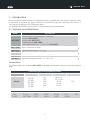
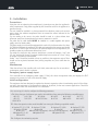
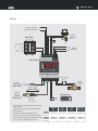
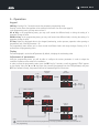
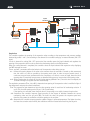
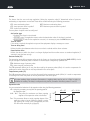
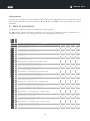
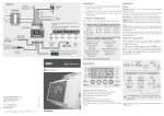
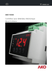
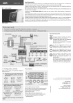
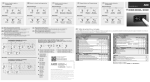
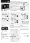
GB
AKO-14560
Electronic expansion valve controller
User Manual
1456H002 Ed.01
1456H002 Ed.01
Page
Index
1.- Introduction ..................................................................................................................................3
2.- Versions and references .................................................................................................................3
Compatibility ..............................................................................................................................3
3.- Installation....................................................................................................................................4
Precautions ................................................................................................................................4
Maintenance ..............................................................................................................................4
Emergency power supply input ...................................................................................................4
Initial configuration ....................................................................................................................4
Wiring ........................................................................................................................................5
4.- Equipment description...................................................................................................................6
Indicators ...................................................................................................................................6
Messages ...................................................................................................................................6
5.-Operation.......................................................................................................................................7
Keypad .......................................................................................................................................7
Display .......................................................................................................................................7
Adjustment of parameters ..........................................................................................................7
Regulation ...........................................................................................................................8
Alarms .................................................................................................................................9
Pressure Probe .....................................................................................................................9
Temperature probe ...............................................................................................................9
Expansion valve....................................................................................................................9
Initial parameters ...............................................................................................................10
6.- Table of parameters .....................................................................................................................10
7.- Technical specifications ................................................................................................................12
AKO Electromecánica thanks and congratulates you for purchasing our product, in whose development and manufacture the most innovative
technology has been used, as well as strict production and quality control processes.
Our commitment to satisfy our customers and our continuous efforts to improve every day can be seen in the various quality certifications we
have obtained. This is a high performance, high technology product. The operation and final performance of the equipment depend on proper
planning, installation, configuration and commissioning. Read this manual carefully before installation, and always follow its instructions. Only
qualified personnel should install or perform technical assistance on this product.
This product is designed to be used in the applications described in the product manual. AKO Electromecánica gives no guarantee of its
operation in any use not foreseen in the manual, and is not responsible for any damage resulting from improper use, configuration,
installation or commissioning.
It is the responsibility of the installer and the customer to comply with and ensure others comply with all regulations applicable to
installations incorporating our products. AKO Electromecánica is not responsible for any damage caused by non-compliance with regulations.
Follow strictly the instructions given in this manual.
To maximise the service life of our equipment, these recommendations should be followed:
Do not expose electronic equipment to dust, dirt, water, rain, humidity, high temperatures, chemicals or corrosive substances
of any sort.
Do not submit the equipment to blows or vibrations nor try to manipulate it differently from shown in the manual.
Never exceed the specifications and limitations indicated in the manual.
Always respect the specified ambient working and storage conditions.
During and after installation, avoid leaving loose, broken, unprotected or damaged wiring, since they might constitute a risk
for the equipment and its users.
AKO Electromecánica reserves the right to make any non-metrology modification to the documentation or the equipment without previous
notice.
2
1456H002 Ed.01
1.- Introduction
Electronic expansion valves controller for refrigeration systems, compatible with most electronic expansion valves
on the market. Its innovative PID algorithm allows you to optimise the evaporator overheating control and, as a
result, improve the efficiency of the refrigeration system.
It is equipped with MODBUS communications for remote monitoring and parametrisation.
2.- Versions and references
MODEL
AKO-14560
DESCRIPTION
Electronic expansion valves control kit consisting of:
-Controller AKO-145601
-Pressure probe AKO-15571
-Temperature probe AKO-15606
-Power supply transformer 115 - 230 V / 24 V AKO-80077
AKO-145601 Spare EEV electronic controller
AKO-15571
Spare pressure probe from -1 to 15 bar
AKO-15572
Optional pressure probe from -1 to 25 bar
AKO-15606
Spare Pt1000 Temperature probe (-100 to 120 ºC)
AKO-80077
Spare power supply transformer 115 - 230 V / 24 V
Compatibility
The following tables show controller AKO-145601 compatibility with electronic expansion valves and refrigerant
gases.
COMPATIBLE ELECTRONIC EXPANSION VALVES
Manufacturer
DANFOSS
ALCO
SPORLAN
CAREL
Models
ETS 12.5
ETS 25B
ETS 50B
ETS 100B
ETS 250
ETS 400
EX4
EX5
EX6
EX7
EX8
SEI 0.5~11
SEI 1.5~20
SEI 30
SEI 100
SEI 175
E2V
COMPATIBLE REFRIGERANT GASES
R-22
R-507C
R-134A
HFO 1234ze
R-404A
R-744
R-407C
R-407A
3
R-410A
R-407F
R-717
R-507A
R-23
1456H002 Ed.01
3.- Installation
Precautions
2
1
3
45
70
115
Using the unit not observing the manufacturer's instructions may alter the appliance's
safety requirements. Only probes supplied by AKO should be used for the appliance to
operate correctly.
The unit should be installed in a place protected from vibrations, water and corrosive
gases, where the ambient temperature does not exceed the values indicated in the
technical data.
For the reading to be correct, the probe should be used in a place without heat
influences apart from the temperature you want to measure or control.
The probe and its cable should NEVER be installed in a conduit together with power
supply, control or feeder cables.
The power supply circuit should be equipped with a switch for its disconnection of at least
2A, 230V, situated near the appliance. The cables are inserted into the rear part and should
be H05VV-F or H05V-K type. The section to be used will depend on local regulations, but
should not under any circumstances be less than 1 mm².
The cables for wiring the relay contacts should have a section of between 1 mm2 and
2.5 mm2 and wire for the one in common should always have a section of 2.5 mm2. Using
of halogen- free cables is recommended.
Probes 1 and 2 should be installed as close as possible to the evaporator output. There
should not be any device between them (valves, peep-holes etc.) that could alter the
reading.
Maintenance
Clean the surface of the controller with a soft cloth, water and soap. Do not use abrasive detergents, petrol, alcohol or solvents.
58
Emergency power supply input
If the controller has an emergency power supply (12 Vdc), this closes the expansion valve, and displays the CLE
message in the event of a fault in the electricity supply.
Initial configuration
This equipment has been designed to regulate the electronic expansion valve via overheating control of the refrigerant gas in the evaporator. Its configuration has been set, by default, for the most common applications. Check that
the parameters match the characteristics of its installation.
Prior to start-up, it is vital to configure the following parameters:
RFT: Select the type of refrigerant gas used in the installation from among the following compatible gases:
0: R-22
6: R-23
12: R-507A
1: R-134A
7: R-507C
2: R-404A
8: R-HFO1234ze
3: R-407C
9: R-744
4: R-410A
10: R-407A
5: R-717
11: R-407F
EM: Select the expansion valve model installed from among the following compatible models:
1: Danfoss ETS 12.5 / 25B 2: Danfoss ETS 50B
3: Danfoss ETS 100B
4: Danfoss ETS 250
5: Danfoss ETS 400
6: Alco EX4
7: Alco EX5
8: Alco Ex6
9: Alco EX7
10: Alco EX8 (330 step/sec) 11: Alco EX8 (500 step/sec) 12: Spolarn SEI 0.5~11
13: Spolarn SEI 1.5~20
14: Spolarn SEI 30
15: Spolarn SEI 100
16: Spolarn SEI 175
17: Carel E2V
SH: Configure the overheating set point
4
1456H002 Ed.01
Wiring
Emergency power
supply 12 Vdc input +
AKO-80077
Electronic
expansion
valve*
24
0
Tr+
RS485
Tr- MODBUS
GND
A+
AB+
B-
IN
24 V
+
115
0
115 V
230 V
230
Mesh
AKO-145601
ºC
%
bar
NC
Com
No
SET
+5V
Signal
Com.
ON /
OFF
S1
Com.
PRG
Power supply
valve
Probe 1
Temperature
AKO-15606
Probe 2
Suction
pressure
AKO-15571
Liquid
solenoid
valve
Max. 25 mts
(AKO-15586)
AKO-D141xx
**
Red +5V
Green signal
Black Common
* The electronic expansion valve must be the
bipolar type.
Select the valve model connected via the
EM parameter.
The table shows the equivalence of
terminals for the most common models.
** Connection/disconnection should be made
via a contact or potential free relay.
Danfoss
ETS
White
Black
Red
Green
A+
AB+
B5
SET
Alco
EX5/6
White
Black
Brown
Blue
Carel
Alco
Yellow
White
Brown
Green
Sporlan
SEI / SEH
Black
White
Red
Green
1456H002 Ed.01
4.- Equipment description
LED ºC
LED bar
LED manual mode
LED Alert
LED Overheating
LED Pressure
ºC
ºC
%
LED Expansion valve openin
LED Temperature
bar
bar
PRG
SET
PRG Key
UP key
DOWN key
SET Key
Indicators
LED ºC: Indicates that the display shows the temperature value in ºC.
LED bar: Indicates that the display shows the pressure value in bars.
LED manual mode: Indicates that the opening amount of the valve has been configured manually (Cor parameter).
LED Alert: Indicates that there is an active alert.
LED Overheating: Indicates that the display shows the overheating value.
LED Pressure: Indicates that the display shows the suction pressure value (Probe 2).
LED Expansion valve opening: Indicates that the display shows the valve opening percentage.
LED Temperature: Indicates that the display shows the temperature value.
Messages
Message
PS
TSD
TsC
MOP
LOP
HS
LS
FRA
STP
CAL
CLE
Description
Problem in the pressure sensor
Probe 1 not connected
Crossed temperature probe
Maximum Operation Pressure (MOP) alarm
Lower Operation Pressure (LOP) alarm
Maximum overheating alarm
Lower overheating alarm
Frost detection alarm
Regulation stopped by external thermostat (ON/OFF Input)
Expansion valve initialisation
Valve closing underway due to fault in the electricity supply (emergency power supply required)
IMPORTANT: In the event of an alarm or fault in any of the probes, the controller closes the liquid
solenoid and expansion valve until the problem is solved.
6
1456H002 Ed.01
5.- Operation
Keypad
PRG key: Pressing it for 5 seconds accesses the parameters programming menu.
Pressing it twice allows the regulation to be restarted in the event of an alarm (see page 9).
In the programming menu, you may return to level 1.
UP N key: In the programming menu, you may scroll around the different levels, or during the setting of a
parameter, change its value.
DOWN Q key: In the programming menu, you may scroll around the different levels, or during the setting of a
parameter, change its value.
SET key: Allows the displayed value to be changed (overheating, suction pressure, expansion valve opening or
temperature) (only if the DM parameter = 0).
The programming menu allows you to move around the different levels and accept changes. Pressing it for 5
seconds exits the programming menu.
Display
The value displayed is set via the DM parameter. By default, it displays the overheating value.
Adjustment of parameters
Using the programming menu, you will be able to configure the various parameters in order to adapt the
controller's operation to the needs of its installation.
In order to access the programming menu, press the PRG key for 5 seconds, or until the message ''PwD'' appears
on the display. Using the N and Q keys enter the password (programmed into the PSS parameter) and press
SET. Once entered correctly, the password will not be requested again for 30 minutes.
5 sec.
Password
request
Enter
password
ºC
bar
ºC
PRG
ºC
bar
bar
Change value
ºC
bar
SET
Accept
changes
Level 1: Menus
ºC
bar
Level 2:
Parameters
Change menu
ºC
ºC
bar
bar
Change parameter
Level 3:
Values
SET
ºC
ºC
bar
bar
Change value
PRG
ºC
bar
SET
Accept
changes
5 sec.
SET
Press the Set button for 5 seconds to exit programming. If no key is pressed for 3 minutes, the controller will
exit programming.
7
1456H002 Ed.01
LIQUID
SOLENOID
EXPANSION
VALVE
ºC
AKO-145601
%
bar
PRG
SET
S1
EVAPORATOR
CONDENSER
S2
LIQUID
CONTAINER
AKO-D141xx
SET
COMPRESSOR
Regulation
The controller regulates the opening of the expansion valve according to the temperature and pressure readings
obtained by probes 1 and 2, and according to the demand for controlled cooling by an external element (ON / OFF
input).
If there is demand for cooling (ON / OFF input active) the controller opens the liquid solenoid and regulates the
opening of the expansion valve in order to obtain the overheating shown on the SH parameter.
When the cooling demand is completed, the controller closes the liquid solenoid and expansion valve, displaying
the STP message on screen.
The OR and ORT parameters define the behaviour of the expansion valve during start up.
OR: Defines the opening degree of the valve at the moment when the controller is started up. We recommend
that this value is as close as possible to the opening work value, in order to ensure smooth control. If
continuous stop and starts are detected for the compressor, or if there is a return of liquid, lower the initial
opening value. If excessively low pressures are detected during start up, increase the initial opening value.
ORT: Defines the duration in seconds of the initial valve opening (defined in OR). Once this time has elapsed, the
controller will begin to regulate the valve automatically.
The regulation parameters (PRO, int, der), determine how opening of the expansion valve is modified in light of
the temperature and pressure variations detected.
PRO: The proportional gain determines how the valve opening varies for each level of overheating variation. If
set to 3%, the valve opening varies 3% per 1.0K of overheating.
If the opening is to unstable, lower the gain value. If the opening to too stable, increase the gain value.
INT: Determines the controller response speed according to the degree of deviation between the current
overheating value and the set point (SH). The lower the value, the greater the response speed and,
therefore, the greater the oscillations are before getting to the set point.
DER: Determines the controller response speed to sudden changes in pressure/temperature. The higher the value,
the faster the corrective action will be, but oscillations will also increase before reaching the set point.
8
1456H002 Ed.01
Alarms
The alarms alert the user and stop regulation (closing the expansion valve) if determined values of pressure,
overheating or temperature are reached. These values are defined using the following parameters:
LSM: Lower overheating alarm
LPM: Lower pressure alarm in probe 2
FPM: Ice alarm in evaporator
HSM: Maximum overheating alarm
MPM: Maximum pressure alarm in probe 2
For every alarm 4 options must be configured:
Activation type
ŸDisabled: The alarm is not activated.
ŸAutomatic reset: The regulation restarts when the deactivation value of the alarm is reached.
ŸManual reset: In order for the regulation to restart, it is necessary to press the PRG button twice.
Turn-on value
If this value is reached, the regulation stops and the equipment displays a message on screen.
Turn-on delay time
Defines the delay time between when the turn-on value is reached and the alarm activates.
Deactivation value
Defines the value at which the alarm is no longer displayed and the machine returns to standard regulation (if
automatic reset has been set up).
Pressure Probe (S2)
The measuring range of the pressure probe set in the factory, on the probe model provided (AKO 15571), should
only be changed if a different probe is installed. It should only be configured by qualified staff.
PSH: Maximum range of pressure probe.
PSL: Lower range of pressure probe.
The PSO parameter allows you to vary the value read by the pressure probe (offset). It is used to compensate for
reading errors when the probe can not be positioned in the correct place.
Temperature probe (S1)
The TSO parameter allows you to vary the value read by the temperature probe (offset). It is used to compensate
for reading errors when the probe can not be positioned in the correct place.
If probe readings have continuous fluctuations, a reading delay may be set as a filter in order to
stabilise the reading. This delay is configured using the FT parameter and affects probes S1 and S2.
Expansion valve
You can customise the behaviour of the expansion valve using the following parameters:
JCR: Using this parameter, you may limit the opening speed of
the expansion valve
COR: This parameter allows a certain opening degree of the
expansion valve to be set. While this option is active,
the opening will remain fixed (unregulated) and the
LED will remain manually lit up (page 6).
9
% opening
URH / URL: They allow the maximum and lower opening
degrees of the expansion valve to be limited.
JCR: OFF
JCR: 10.0%
100
0
10 sec.
t
1456H002 Ed.01
Initial parameters
Using the INI parameter, all of the parameters can be reset to their default values. For this to take effect, select
the parameter and enter the password using the N and Q keys. Press SET to reset the controller to its factory
parameters.
6.- Table of parameters
The equipment's operation functions are divided into 3 different groups.
The Def. column indicates the default parameters set in the factory. Temperature values are expressed in ºC.
(Equivalent temperature in ºF) and the pressure values in bar (equivalent pressure in psi).
Level 2
Level 1
GROUP 1
Description
(Sec.)
(Sec.)
Min.
0.5
0
0
0.1
0
0
Def.
10
50
5
3
120
30
0
1
2
lSS Lower overheating alarm activation value
LSt Lower overheating alarm turn-on delay time
lsC Lower overheating alarm deactivation time
Maximum pressure alarm in probe 2
MpM
0: Deactivated 1: Automatic reset 2: Manual reset
(K)
(Sec.)
(K)
0.5
1
1
3
15
5
30
300
30.5
0
1
2
Mps Maximum pressure alarm activation value
Mpt Maximum pressure alarm turn-on delay time
MpC Maximum pressure alarm deactivation time
Maximum overheating alarm
HSM
0: Deactivated 1: Automatic reset 2: Manual reset
(bar/psi)
(Min.)
(bar/psi)
0.1
1
0.1
9
1
8
99.9
15
99.9
0
0
2
HSS Maximum overheating alarm activation value
HST Maximum overheating alarm turn-on delay time
HSC Maximum overheating alarm deactivation time
Freeze alarm
FPM
0: Deactivated 1: Automatic reset
2: Manual reset
(K)
(Min.)
(K)
10.0
1
7.0
30
3
27
40.0
600
37.0
0
0
2
FPS Maximum freeze alarm activation value
FPT Freeze alarm turn-on delay time
FPC Maximum freeze alarm deactivation time
Lower pressure alarm in probe 2
LPM
0: Deactivated
1: Automatic reset 2: Manual reset
(ºC/ºF)
(Sec.)
(ºC/ºF)
-100
5
-97
0
30
3
392
200
392
0
1
2
LPS Lower pressure alarm activation value
LPT Lower pressure alarm turn-on delay time
LPC Lower pressure alarm deactivation time
(bar/psi)
(Sec.)
(bar/psi)
-1
5
0.7
0
5
0.3
25
200
25.3
SH
1.Pr
or
ort
pro
int
der
lsM
Overheating set point
Initial opening for valve start up
Duration of initial start up opening
Proportional gain
Integral time
Derivative time
Value
(K)
(%)
(Sec.)
Lower overheating alarm
0: Deactivated 1: Automatic reset 2: Manual reset
10
Max.
30
100
300
99.9
999
999
1456H002 Ed.01
Level 2
Level 1
2.Pr
GROUP 2
Description
0: Bar 1: Psi
0: ºC
1: ºF
Value
pu
Tu
Pressure units
Temperature units
EM
Selection of expansion valve model connected
1: Danfoss ETS 12.5 / 25B
2: Danfoss ETS 50B
3: Danfoss ETS 100B
4: Danfoss ETS 250
5: Danfoss ETS 400
6: Alco EX4
7: Alco EX5
8: Alco EX6
9: Alco EX7
10: Alco EX8 (330 step/sec) 11: Alco EX8 (500 step/sec) 12: Spolarn SEI 0.5~11
13: Spolarn SEI 1.5~20
14: Spolarn SEI 30
15: Spolarn SEI 100
16: Spolarn SEI 175
17: Carel E2V
TST Total steps for expansion valve*
DSP Expansion valve speed*
GROUP 3
Description
3.Pr
Value
pss Parameter access password
rft
Type of refrigerant gas used:
1: R-134A
2: R-404A 3: R-407C
7: R-507C 8: R-HFO1234ze 9: R-744
PSH
PSL
PSO
TSO
JCR
UrH
UrL
Ft
COR
Pressure probe range (Maximum)
Pressure probe range (Lower)
Pressure probe calibration (S2)
Pressure probe calibration (S1)
Expansion valve opening speed limit
Maximum expansion valve opening limit
Lower expansion valve opening limit
Reading delay for probes (S1 and S2)
Lower expansion valve forced opening value
DM
Display mode:
0: Displays options 1 to 4 sequentially
2: Suction pressure value (Probe 2)
4: Temperature value (Probe 1)
4: R-410A
10: R-407A
0: R-22
5: R-717
6: R-23
11: R-407F 12: R-507A
(bar/psi)
(bar/psi)
(bar/psi)
(ºC)
(%)
(%)
(%)
(Sec.)
(%)
1: Overheating value (ºK)
3: Valve opening (%)
5: Overheating set point
CID Communication direction
CSP Communication speed
INI Initial settings (enter password and press SET)
(BPSx100)
Min.
0
0
Def.
0
0
Max.
1
1
1
1
17
0
0
260
250
999
999
Min.
0
Def.
5
Max.
999
0
1
12
-1
-1
-9.9
-19.9
0.1
0
0
0.1
0.0
15
-1
0
0
OFF
100
0
1
OFF
99
99
9.9
19.9
9.9
100
100
10.0
100
0
1
14
1
48
0
1
96
0
254
384
999
* The TST and DSP parameters are adjusted automatically when the expansion valve model is selected. They
should only be changed by qualified staff. AKO is not responsible for any damage that may be inflicted on the
installation.
11
1456H002 Ed.01
7.- Technical specifications
Controller AKO-14601
Power supply ........................................................................................................24 V~ +10% / -15%, 50/60 Hz
Consumption including expansion valve ............................................................................................................1A
Output for expansion valve..............................................................................Valves with a bipolar stepper motor
Compatibility with expansion valves....................................................................................................(see page 3)
Maximum consumption of expansion valve................................................................................................700 mA
Opening control precision................................................................................................1/1000 (0.0 to 100.0 %)
Working ambient temperature .................................................................................-10 to 50 ºC, moisture >90 %
Storage ambient temperature ..................................................................................-20 to 60 ºC, moisture >90 %
Relay solenoid valve...............................................................................................................SPST 2 (2) A 250 V~
Compatibility with refrigerant gases....................................................................................................(see page 3)
Communications ......................................................................................................MODBUS RTU / ASCII (Rs485)
Terminals ........................................................................................................................Screw-on, up to 2.5 mm2
Dimensions ......................................................................................................................................(Vsee page 4)
Assembly...................................................................................................................................................DIN rail
Pressure probe AKO-15571 / AKO-15572
Power supply .......................................................................................................................................5 Vcc ±5%
Output.........................................................................................................................DC 0.5 to 4.5 V, ratiometric
Protection degree...........................................................................................................................................IP65
Measuring range AKO-15571 .........................................................................................................-1 to 15 bar
AKO-15572 .........................................................................................................-1 to 25 bar
Precision..................................................................................................................................................±0.25%
Maximum pressure supported......................................................................1.5 times the maximum reading range
Maximum peak pressure ................................................................................3 times the maximum reading range
Working ambient temperature............................................................................................................-40 to 80 ºC
Wiring
Black .....................................................................................................................................Common
Red...............................................................................................................................................+5V
Green.........................................................................................................................................Signal
Length of cable ...............................................................................................................................................2 m
Temperature probe AKO-15606
Type of sensor............................................................................................................................................Pt1000
Protection degree...........................................................................................................................................IP67
Measuring range............................................................................................................................-100 to 120 ºC
Precision ....................................................................................................................................± 0.3 ºC to 25 ºC
Length of cable ...............................................................................................................................2 m (0.5 mm2)
Response time.........................................................................................................................................1 second
Transformador AKO-80077
Input .................................................................................................................................115/230 V~ 50 / 60 Hz
Output .......................................................................................................................................24 V~ 50 / 60 Hz
Assembly...................................................................................................................................................DIN rail
12
1456H002 Ed.01
13
1456H002 Ed.01
14
1456H002 Ed.01
15
Tel.: +34 902 333 145
Fax: +34 938 934 054
www.ako.com
We reserve the right to supply materials that might vary slightly to those described in our Technical Sheets. Updated information is available on our website.
351456002 REV.00 2015
AKO ELECTROMECÁNICA , S.A.L.
Avda. Roquetes, 30-38
08812 • Sant Pere de Ribes.
Barcelona • Spain.