1
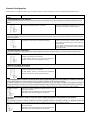
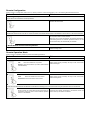
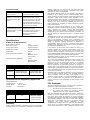
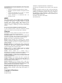
Z-Wave Remote Control - Instructions 200ZW-US-W & 200ZW-EU-W Getting Started Introduction Before using the Remote Control, the battery must be fully charged to obtain the maximum battery lifetime. Thank you for purchasing this TrickleStar product. With this product you will be able to control a range of Z-Wave™ devices. About Z-Wave The TrickleStar Remote Control is a Z-Wave™ enabled device and is compatible with Z-Wave™ enabled devices from a range of manufacturers. Z-Wave™ is an interoperable two way RF mesh networking technology. Each mains powered device in a Z-Wave™ network is designed to act as a repeater. Repeaters can re-transmit the RF signal to ensure that the signal is received by its intended destination by routing the signal around obstacles and radio dead spots. The Z-Wave Remote Control is designed to be used with a range of Z-Wave compliant devices such as dimmers, drape controllers and motorised screens. The product is simple yet supports a range of advanced Z-Wave network functionality. Features Configuration Switch: The product has a slide switch under the rubber end piece, which can set the product in “Operation Mode” and “Configuration Mode”. Configuration Mode: In Configuration Mode the product can Include, Exclude and create / remove Assigned Associations, as well as replicate the Routing Table to and from other Z-Wave devices. Inclusion Controller: The product can act as a Z-Wave Inclusion Controller in networks containing a Z-Wave Static Controller (SIS) such as Gateways, Controls Panels, Set Top Boxes etc. Configurable Buttons: The 2 buttons control a single load or a Group. The buttons can be configured to provide On/Dim Up, Off/Dim Down or All On/Off switching. USB Rechargeable Battery: The product is powered by a rechargeable lithium battery and can be recharged via a standard USB port. • Open the Rubber Cap at the bottom of the remote. • Insert the mini USB connector on the supplied USB Cord into the USB connector in the remote. • Connect the USB A connector of the USB cord to any USB port on a PC. • When the Remote is being charged, the LED Indicator will blink Green as long the battery is being charged. When fully charged, the LED Indicator will stop illuminating. Charge the battery for 4 hours to fully charge the battery. When the battery level is low, the LED Indicator will blink Red 3 times (1 sec On, 1 sec Off, 1 sec On) after any Operation. Z-Wave Network Setup Setup of the Z-Wave Network is done in 3 steps: Step 1: Physical Install Of Devices • Plug-in or hardwire the Z-Wave Devices into the location where they will be used. Step 2: Include Devices • When Including Z-Wave Devices to the Remote it will configure the Devices to be a part of the network. • Note: you cannot control the Included device at this stage using the remote – you have to create an Association between the Remote and the Device (step 3). Step 3: Create Associations • By creating Associations between the Remote and a ZWave Device(s) you are able to control the Device(s) using the Remote Control Buttons. About Configuration Mode To access Configuration Mode the Configuration button must be set to the Configuration position and the “Up” button must be pressed-and-held for 2 seconds until the LED illuminates Green. Wall Mounting Cradle: The product can be wall mounted using the wall-mounting cradle. The following page shows the various Configuration Options. Installation Examples For installation example please refer to the Quick Installation Guide Network Configuration Switch must be in Configuration position and ʻUpʼ button pressed for 2 seconds followed by one of the following Remote Button Presses. Remote Button Press Action on Z-Wave Device Notes 1: Including Device to the Remote By Including a Z-Wave Devices to the remote they become a part of the network and can be controlled by the remote and other devices in the network. “Up” Button one time Press the Inclusion Initiator of the Device to be Included (normally an Operation Button of a product). Note: When a Device is Included to the Network it cannot be controlled by the Remote as is must be Associated to the Remote Operation Buttons. 2: Excluding Device from the Remote By Excluding a Z-Wave Device from the remote they will be removed from the network and can no longer be controlled by the remote and other devices in the network. “Down” Button one time. Press the Exclusion Initiator of the Device to be Excluded (normally the same button as the Inclusion Initiator). Note 1: When the Device is Excluded from the Network it can be moved to another location and be re-Included to the same Network or be Included into another Network. Note 2: When Excluding a Device from a Network, its Association to the Remote Operations Buttons will also be deleted. 3: Create Assigned Association Assigned Association is a “binding” between two devices enabling one of them to control the other, e.g. movement sensor switches On/Off a lamp due to a movement. “Up” Button two times. 1: With Remote Control in hand press the Association Initiator on the Device to be controlled. 2: With Remote Control in hand press the Association Initiator on the Device controlling the other device. 4: Remove Assigned Association Removes the “binding” between two devices. “Down” Button two times. 1: With Remote Control in hand press the Association Initiator on the Device to be controlled. 2: With Remote Control in hand press the Association Initiator on the Device controlling the other device. 5: Including another Controller to the Remote and/or Replicating Network Information to another Controller In basic Z-Wave Networks two types of Controllers exist: (1) Primary Controllers and (2) Secondary Controllers. The Primary Controller is the one containing the updated Network Information. Every time Network changes are made (Devices Included or Excluded) the Network Information of the Primary should be Replicated to all the Secondary Controllers to obtain optimal network performance. To Replicate the Network from the Remote Control (if Primary) to another Controller (Secondary) the following steps should be followed: “Up” Button one time Press the Controller Replication Receive initiator on the Secondary Controller. Replication will start and Remote Control LED Indicator will blink Green when transferring Network Information. 6: Include the Remote to another Controller and/or Replicating Network Information from another Controller When Including the remote to another Controller the remote automatically becomes a Secondary Controller. To Replicate the Network Information to the Remote Control (if Secondary) from another Controller (Primary) following steps should be followed: “Up” Button four time Press the Controller Replication Transmit initiator on the Primary Controller. Replication will start and Remote Control LED Indicator will blink Green when transferring Network Information. Remote Configuration Switch must be in Configuration position and ʻUpʼ button pressed for 2 seconds followed by one of the following Remote Button Presses. Button Press Notes 1: Clearing Group Association Devices which are Associated to the Group Buttons “Up” Button three times When clearing all Associations from the remote buttons to devices will be removed. 2: Enabling ʻAll On / Offʼ Functionality The Remote control can act as an All On / All Off Controller, which allows all the devices in the Network to be turned On or Off at the same time. “Up” Operation Button five times Note 1: All Associations, which have previously been made to the Operation Buttons will be deleted. Note 2: If one or more Associations are made as described in “Associating Devices to Remote Operation Buttons” the All On/Off functionality will automatically be disabled. 3: Reset Remote Control to Factory Default Long Press ʻUpʼ Button for 10 sec. LED Indicator will alternate Red, Yellow and Green while remote is being reset. Remote Operation Mode Switch must be in Operation position to perform the following operations. Button Press Notes 1: On / Dim Up ON: Press-and-release the ʻUpʼ button. Dim Up: Press-and-hold the ʻUpʼ button (LED Indicator will blink Green). Relay devices (binary switches) will stay in their current state when dimming up. 2: Off / Dim Down OFF: Press-and-release the ʻDownʼ button. Dim Down: Press-and-hold the ʻDownʼ button Relay devices (binary switches) will stay in their current state when dimming down. 3: Create Association Creates an Association between the Remote and the Device, enabling you to control the Device using the operation button on the Remote. Press-and-hold ʻUpʼ button while pressing the button on the Device, which you want to control with the operation buttons on the Remote. If Devices are already Associated to the Remote, these will start to Dim Up until button is released. Troubleshooting Problem Solution I cannot Switch On, Off or Dim my devices. The switch might be in “Configuration Mode” position Every time I try to Include Devices to my network, I keep getting errors (Red LED) The controller might be a Secondary Controller. Only a Primary Controller may be used to Include Devices into a network. The module might be part of a different network. Reset the Device by performing an Exclude. I am trying to turn On/Off a Device Associated to the Operation Button, but it will not turn On/Off. Check to be sure there is power supplied to the Device. The module might not have be Associated to the Operation Buttons. Try to create an Association. Specifications Z-Wave & RF Specifications Z-Wave Protocol Release 5.01 Basic Device Class Portable Controller Generic Device Class Remote Controller Specific Device Class Portable Remote Ctrl Z-Wave Chip ZW0301 Command Classes Controlled Basic Multilevel Switch Version Multilevel Switch Binary Switch RF EU Data Rate Frequency US 9.6kbps / 40kbps 9.6kbps:868.42 MHz 40kbps: 868.40 MHz Range This Standard Warranty does not cover damage, fault, failure or malfunction due to external causes, including accident, abuse, misuse, problems with electrical power, servicing not authorized by TrickleStar, usage and/or storage and/or installation not in accordance with Product instructions, normal wear and tear, act of God, fire, flood, war, act of violence or any similar occurrence. Any attempt by any person other than TrickleStar personnel or any person authorized by TrickleStar, to adjust or repair the Products shall void the warranty. During the one-year period beginning on the invoice date, TrickleStar will repair or replace Products returned to TrickleStarʼs facility. Customer must prepay shipping and transportation charges, and insure the shipment or accept the risk of loss or damage during such shipment and transportation. TrickleStar will ship the repaired or replacement products to Customer freight prepaid. TrickleStar does not give any warranty that the Products are fit for any particular purpose and this Standard Warranty is given in place of all warranties, conditions, terms, undertakings and obligations implied by statute, common law, trade usage, course of dealing or otherwise including warranties or conditions of merchantability, fitness for purpose, satisfactory quality and/or compliance with description, all of which are hereby excluded to the fullest extent permitted by law. If any provision of these Terms and Conditions is held by any competent authority to be invalid or unenforceable in whole or in part, the validity of the other provisions of these Terms and Conditions and the remainder of the provisions in question shall not be affected thereby. Where implied conditions and warranties cannot be excluded due to local trade practices legislation, TrickleStarʼs liability for breach of such conditions and warranties shall be limited, at TrickleStar option, to Binary Switch Command Classes Supported affecting normal use for a period of one year from invoice date (“Standard Warranty”). This warranty is extended to the original purchaser only and is not transferable. 9.6kbps:908.42 MHz 40kbps: 908.40 MHz Typical 30 meters Specifications & Regulatory Approvals FOR INDOOR USE (a) in the case of products, the replacement of the products or the supply of equivalent products; the repair of such products; the payment of the cost of replacing the products or of acquiring equivalent products; or the payment of the cost of having the products repaired OR (b) in the case of services, the supplying of services again; or the payment of the cost of having the services supplied again. TrickleStar total liability in respect of each event or series of connected events shall not exceed the total price paid for the purchase of product/s. TrickleStar shall not be liable for Products not being available for use, or for data or software, which is lost, corrupted, deleted or altered. TrickleStar shall not be liable to the Customer for any incidental, indirect, special or consequential damages arising out of or in connection with the purchase, use or performance of products or services, even if TrickleStar has been advised of their possibility. Operating Temp: 0° to 45°C FCC Statement Storage Temp: -20ºC to +60ºC Humidity: 5 to 90% N/C This device complies with part 15 of the FCC rules. Operation of this device is subject to the following conditions; REGION RF EU CE US FCC, CSA OTHER 2002/95/EG (RoHs) 2002/96/EC (WEEE) 1999/5/EC (RTTE) Z-Wave Certified Warranty Unless specified otherwise, TrickleStar warrants that TrickleStar Products will be free from defects in materials and workmanship • This device may not cause harmful interference, and • This device must accept any interference including Interference that may cause undesired operation. Note: This equipment has been tested and found to comply with the limits for a Class B digital device, pursuant to Part 15 of the FCC Rules. These limits are designed to provide reasonable protection against harmful interference in a residential installation. The equipment generates, uses and can radiate radio frequency energy and if not installed and used in accordance with the instructions, may cause harmful interference to radio communications. However, there is no guarantee that interference will not occur in a particular installation. If this equipment does cause harmful interference to radio or television reception, which can be determined by turning the equipment on and off, the user is encouraged to try to correct the interference by one or more of the following measures; • Reorient or relocate the receiving antenna or device. • Increase the separation between the equipment and the receiver. • Connect the equipment into an outlet on a different circuit to which the receiver is connected. • Consult TrickleStar or an experienced radio / TV • technician for help. WEEE This product complies with the WEEE Directive (2002/96/EC) marking requirements. The affixed label indicates that you must not discard this electrical / electronic product in domestic household waste. Product Category: With reference to the equipment types in the WEEE Directive Annex 1, this product is classed as category 9 “Monitoring and Control Instrumentation product”. DO NOT DISPOSE IN DOMESTIC HOUSEHOLD WASTE. To return unwanted products, contact the manufacturers website shown on the product or your local sales office or distributor. Glossary Association: a ʻbindingʼ between the Remote Operation Buttons and a Device, i.e. On, Off, Dim Up, Dim Down etc. Association Initiator: is the interface with which a product gets Associated to Controller. This is typically the Operation Button of a product e.g. a light switch. Please refer to manual of product. Device: Any item that is Associated to the Controller Exclude: Devices Excluded from a Network using a Primary /Inclusion Controller is removed from the Network and can no longer be controlled by the Devices in the Network. Please refer to manual of product. Exclusion Initiator: is the interface with which a product gets Excluded from a network. This is typically the Operation Button of a product e.g a light switch or Exclusion Button on a Remote control etc. Please refer to manual of product. Group: A “Group” is a group of devices, which are controlled simultaneously by the Group Operation Buttons. The Remote controls up to 32 Devices in the Group. Include: Devices Included into a Network using a Primary/Inclusion Controller is inserted into the Network and can be there after be controlled by the Devices in the Network. Inclusion Controller: Controller within a SUC/SIS Network used to configure a Network. It contains network information about other devices within the Network. Inclusion Initiator: is the interface with which a product gets Included to a network. This is typically the Operation Button of a product e.g. a light switch or Inclusion Button on a Remote control etc. Please refer to manual of product. Primary Controller: The first Controller used to setup the a Network in a Primary/Secondary Controller network. It contains network information about other devices within the Network. Only Primary Controller can Include Devices to a Network. Secondary Controller: Additional Controller used in a Network. It contains network information about other devices within the Network. Primary Controllers cannot Include new Devices to a Network. Copyright & Disclaimer © TrickleStar Ltd. All rights reserved. TrickleStar is a registered trademark of TrickleStar Ltd. All other logos and trademarks are the property of their respective owners. Disclaimer: TrickleStar reserves the right to change specifications or designs described in this manual without notice and without obligation. Any typographical, clerical or other error or omission in this document or other documents or information issued by TrickleStar shall be subject to correction without any liability on the part of TrickleStar without notice. Save Money. Save Power. Saver Earth www.tricklestar.com