1
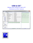
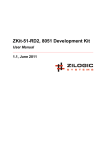
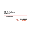
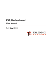
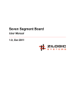
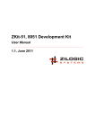
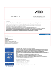
Temperature Sensor Board
User Manual
1.0, Oct 2011
Temperature Sensor Board User Manual
Rev. 1.0
This work is licensed under the Creative Commons Attribution-Share Alike 2.5 India License. To view a
copy of this license, visit http://creativecommons.org/licenses/by-sa/2.5/in/ or send a letter to Creative
Commons, 171 Second Street, Suite 300, San Francisco, California, 94105, USA.
Temperature Sensor Board User Manual
Rev. 1.0
Table of Contents
1. Temperature Sensor Board .....................................................................................................
1. Overview .......................................................................................................................
2. Board Features ..............................................................................................................
3. Locating Components .....................................................................................................
4. Description .....................................................................................................................
5. Power Supply ................................................................................................................
6. Remote Sensor ..............................................................................................................
7. Connectors and Headers ................................................................................................
8. Specifications .................................................................................................................
2. Board Usage ..........................................................................................................................
1. I²C Bus Overview ...........................................................................................................
2. Accessing Device Registers ............................................................................................
3. Common Usage Scenarios .............................................................................................
A. Legal Information ...................................................................................................................
1. Copying .........................................................................................................................
2. Disclaimers ....................................................................................................................
Zilogic Systems
1
1
1
1
1
2
2
3
4
5
5
5
5
9
9
9
Page iii
Temperature Sensor Board User Manual
Rev. 1.0
Chapter 1. Temperature Sensor Board
1. Overview
The temperature sensor board is based on NXP’s SA56004 temperature sensor which can be interfaced
through the I²C bus. Temperatures can be measured with an accuracy of ±1 °C.
2. Board Features
• SA56004, I²C temperature sensor
• Remote temperature measurement
• Over temperature alert interrupt
• External device control, without software intervention
• LED indications for testing/debugging
• Can measure temperatures from -40 °C to 125 °C.
3. Locating Components
The location of the components on the board is indicated in the following diagrams.
Figure 1.1. Front View
4. Description
A block diagram representation of the board is shown below. The I²C temperature sensor can be
accessed through the 10 pin FRC connector from the motherboard. The temperature sensor can
measure the local IC temperature, and a remote temperature. For measuring remote temperatures a
transistor connected to the REMOTE SENSOR port is used as the sensing element.
Zilogic Systems
Page 1
Temperature Sensor Board User Manual
Rev. 1.0
An alert interrupt is raised when the temperature exceeds a configurable set point. The signal T_CRIT
is raised when the temperature exceeds a configurable critical set point. This is useful for automatic
temperature regulation applications, where the system is to be shutdown or a fan is to be switched ON,
without software intervention.
The board provides a isolated 12V/1Amp power switching. The board switches ON the 12V/1Amp DC
OUT on T_CRIT assertion and switches OFF the DC OUT on T_CRIT de-assertion. DC OUT can be
connected to a 12V fan to switch it on and off automatically on thermal critical points.
Figure 1.2. Block Diagram
5. Power Supply
The temperature sensor board is powered from the motherboard through FRC-10 header.
The DC OUT can be used for controlling an external device, like a fan or a relay. If external device control
is required, an external 12V/1Amp DC power should be provided through the DC IN screw terminal or
through the +12V IN power jack. This will be driven out through DC OUT on T_CRIT assertion.
Output Voltage
12V
Output Current
1A
Polarity
6. Remote Sensor
For remote temperature measurement, the Emitter-Base diode of a BJT, is used as the sensing element.
Note that two-lead diodes cannot be used, since the ideal factor of two-lead diodes is incompatible with
the temperature sensor. The recommended transistors are listed below.
• 2N3904 (NPN)
• 2N3906 (PNP)
An example of an 2N3904 NPN transistor connected to the REMOTE SENSOR connecter is shown in
the following diagram.
Zilogic Systems
Page 2
Temperature Sensor Board User Manual
Rev. 1.0
Figure 1.3. Connecting Sensing Element
The wires connecting the sensing element can be 8 inches long. For longer wire lengths a shielded
twisted pair is recommended. Please see the recommendations under the section "Mounting" of the
SA56004X data sheet.
7. Connectors and Headers
7.1. I2C Connector
The temperature sensor board can be interfaced to a motherboard through the I2C, 10 pin FRC,
connector. The signal details are given below.
Table 1.1. FRC-10 Pin Connector
Pin #
Signal
Signal Type
1
VCC
Supply from motherboard
2
Not Used
-
3
Not Used
-
4
SCL
Open collector
5
SDA
Open collector
6
Not Used
-
7
Not Used
-
8
Not Used
-
9
INTR#
TTL Out
10
GND
-
7.2. REMOTE SENSOR Connector
When a remote temperature has to be measured, the remote temperature sensing element is connected
to the REMOTE SENSOR header.
Table 1.2. REMOTE SENSOR Connector
Pin #
Signal
1
GND
2
D+
3
D-
4
GND
7.3. DC OUT and DC IN Connector
This DC OUT connector provides a 12V DC from the DC IN connector when T_CRIT is asserted. This
is typically used for controlling a fan, or triggering a system shutdown, when the temperature exceeds
a configured critical set point.
Zilogic Systems
Page 3
Temperature Sensor Board User Manual
Rev. 1.0
Table 1.3. DC OUT and DC IN Connector
Pin #
Signal
1
VCC
2
GND
8. Specifications
Table 1.4. Specifications
Parameter
Value
Condition
Power Supply
Supply Voltage
5V
Supply Current
550uA - 600uA
16Hz conversion rate FIXME
Temperature
Measurement Range
-40 °C - 125 °C
Local Temp. Error
±2 °C
+60 °C to +100 °C
±3 °C
-40 °C to +125 °C
±1 °C
+60 °C to +100 °C
±3 °C
-40 °C to +125 °C
Remote Temp. Error
I²C Bus
Input High Voltage
2.2V - 5.0V
Input Low Voltage
0.0V - 0.8V
Max. SCL frequency
400kHz
7-bit Device Address
0x48
Zilogic Systems
Page 4
Temperature Sensor Board User Manual
Rev. 1.0
Chapter 2. Board Usage
1. I²C Bus Overview
The I²C is a simple two wire interface for on-board communication. One of the wires is data and the
other is clock. The I²C is a master slave bus. The master is initiates the communication and the slaves
respond to it. Each slave on the bus has an address to uniquely identify itself.
Figure 2.1. I²C Bus
There are typical two operations that the master can perform i2c_read and i2c_write. During the
i2c_read operation the master specifies the slave address and the no. of bytes to read. During the
i2c_write operation the master specifies the slave address and the bytes to be written.
2. Accessing Device Registers
The devices usually have a set of registers. Each register is given an address. When a register is to be
read or written, the address is first written to the device and then data is read or written to the register.
The register address specified is stored within the device. For successive reads to the same register
the address need not be specified again.
3. Common Usage Scenarios
This section shows the pseudo-code for various common usage scenarios. The I²C operations are
represented by the following two functions.
data = i2c_read(dev_addr);
i2c_write(dev_addr, data);
The dev_addr is the 7-bit I²C address of the device to read/write. data is the byte to be read/written.
In the case of i2c_read() the byte read from the device is returned. In the case of i2c_write() the
byte to be written to the device is passed to the function.
Scenario I: Measuring Local Temperature. To measure the local temperature the following pseudo
code can be used.
lthb_reg = 0x0;
i2c_write(0x48, lthb_reg); ❶
temp = i2c_read(0x48); ❷
❶
❷
Write the register address of the local temperature register (LTHB), 0x0.
Read the contents of LTHB. The read byte is the local temperature in degree Celsius.
Scenario II: Measuring Remote Temperature. The temperature sensing element, is first connected
to the SENSOR PORT as shown in the following diagram.
Zilogic Systems
Page 5
Temperature Sensor Board User Manual
Rev. 1.0
Figure 2.2. Connecting Sensing Element
The following pseudo code is used to measure the remote temperature.
rthb_reg = 0x1;
i2c_write(0x48, rthb_reg); ❶
temp = i2c_read(0x48); ❷
❶
❷
Write the register address of the remote temperature register (RTHB), 0x1.
Read the contents of RTHB. The read byte is the remote temperature in degree Celsius.
Scenario III: Interrupt Notification. In certain applications, an action has to be taken when the
temperature exceeds a specific temperature range. This can be done by periodically reading the
temperature register. But a much more efficient method is possible. The temperature sensor can
interrupt the CPU, when the temperature exceeds a specified range. The CPU then performs the
required action, and acknowledges the interrupt.
Figure 2.3. Alert Interrupt
The temperature sensor has an ALERT signal that can be used as an interrupt signal. The set points
for local and remote temperatures can be configured individually. An example circuit configuration is
shown in Figure 2.3, “Alert Interrupt”. Note that since the ALERT is an open collector output a pull-up
resistor (typically 10k) is required. The pseudo code for enabling interrupt notification when the local
temperature exceeds the range 10 °C - 60 °C is given below.
lhs_reg = 0x0B;
i2c_write(0x48, lhs_reg); ❶
temp = 60;
i2c_write(0x48, temp); ❷
lls_reg = 0x0C;
i2c_write(0x48, lls_reg); ❸
temp = 10;
i2c_write(0x48, temp); ❹
❶
❷
Write register address of the Local High Setpoint register (LHS), 0x0B.
Write local high setpoint temperature 60 °C to LHS.
Zilogic Systems
Page 6
Temperature Sensor Board User Manual
❸
❹
Rev. 1.0
Write register address of the Local Low Setpoint register (LLS), 0x0C.
Write local low setpoint temperature 10 °C to LLS.
The pseudo code for the interrupt handler in given below.
lthb_reg = 0x0;
i2c_write(0x48, lthb_reg);
temp = i2c_read(0x48); ❶
sr_reg = 0x2;
i2c_write(0x48, sr, reg);
status = i2c_read(0x48); ❷
❶
❷
Read the local temperature.
Read the status register to acknowledge the interrupt.
Scenario IV: Thermal Watchdog. In certain applications, the temperature sensor is required to
autonomously control an external device, when the temperature exceeds a setpoint. This must be
done without the intervention of the software. One such application is the thermal watchdog, where
the temperature sensor shuts down the system being monitored or switches a cooling fan when the
temperature over shoots the setpoint.
Figure 2.4. Thermal Watchdog
The temperature sensor can act like a thermal watchdog using the T_CRIT signal. The T_CRIT
becomes low when the temperature exceeds the T_CRIT setpoint. The T_CRIT signal can in-turn
control a cooling fan. The T_CRIT setpoint can be configured individually for local and remote
temperatures. An example circuit configuration is shown in Figure 2.4, “Thermal Watchdog”. The
T_CRIT is held low till the temperature drops by a configurable hysteresis amount. hysteresis on the
T_CRIT signal is shown in the figure below.
Figure 2.5. Hysteresis
The default T_CRIT setpoint is 85 °C. The default T_CRIT hysteresis is 10 °C. The following pseudocode sets the T_CRIT setpoint to 75 °C, and the hysteresis to 20 °C.
Zilogic Systems
Page 7
Temperature Sensor Board User Manual
Rev. 1.0
lcs_reg = 0x20;
i2c_write(0x48, lcs_reg); ❶
temp = 75;
i2c_write(0x48, temp); ❷
th_reg = 0x21;
i2c_write(0x48, th_reg); ❸
hyst = 20;
i2c_write(0x48, hyst); ❹
❶
❷
❸
❹
Write the register address of the local T_CRIT register (LCS), 0x20.
Write the setpoint to LCS. The local temperature setpoint in degree Celsius, is written to the register.
Write the register address of the T_CRIT hysteresis register (TH), 0x21.
Write the hysteresis amount to TH. The hysteresis amount in degree Celsius, is written to the
register.
Zilogic Systems
Page 8
Temperature Sensor Board User Manual
Rev. 1.0
Appendix A. Legal Information
1. Copying
This work is licensed under the Creative Commons Attribution-Share Alike 2.5 India License. To view a
copy of this license, visit http://creativecommons.org/licenses/by-sa/2.5/in/ or send a letter to Creative
Commons, 171 Second Street, Suite 300, San Francisco, California, 94105, USA.
2. Disclaimers
NO WARRANTY. ZILOGIC SYSTEMS' DEVELOPMENT KITS (AND TECHNICAL SUPPORT,
IF ANY) ARE PROVIDED "AS IS" AND WITHOUT ANY WARRANTY OF ANY KIND, EXPRESS
OR IMPLIED. TO THE MAXIMUM EXTENT PERMITTED UNDER APPLICABLE LAWS, ZILOGIC
SYSTEMS EXPRESSLY DISCLAIMS ALL WARRANTIES, EXPRESS OR IMPLIED, INCLUDING
BUT NOT LIMITED TO IMPLIED WARRANTIES OF MERCHANTABILITY, FITNESS FOR A
PARTICULAR PURPOSE, AND NONINFRINGEMENT. ZILOGIC SYSTEMS DOES NOT WARRANT
THAT THE FUNCTIONS CONTAINED IN ZILOGIC SYSTEMS' DEVELOPMENT KITS WILL
MEET YOUR REQUIREMENTS, OR THAT THE OPERATION WILL BE UNINTERRUPTED OR
ERROR-FREE, OR THAT DEFECTS IN ZILOGIC SYSTEMS' DEVELOPMENT KITS WILL BE
CORRECTED. FURTHERMORE, ZILOGIC SYSTEMS DOES NOT WARRANT OR MAKE ANY
REPRESENTATIONS REGARDING THE USE OR THE RESULTS OF THE USE OF THE
ZILOGIC SYSTEMS' DEVELOPMENT KITS IN TERMS OF THEIR CORRECTNESS, ACCURACY,
RELIABILITY, OR OTHERWISE. SOME JURISDICTIONS DO NOT ALLOW THE EXCLUSION OF
IMPLIED WARRANTIES, SO THE ABOVE EXCLUSION MAY NOT APPLY OR MAY BE LIMITED.
Limitation of Liability. Zilogic Systems' development kits are not designed, authorised or warranted
to be suitable for use in medical, military, aircraft, space or life support equipment, not in applications
where failure or malfunction of a Zilogic Systems product can reasonably be expected to result in
personal injury, death or severe property or environmental damage. Zilogic Systems accepts no liability
for inclusion and/or use of Zilogic Systems' development kits in such equipment or applications and
therefore such inclusion and/or use is at the customer’s own risk.
Zilogic Systems
Page 9