1
SYSdev
Program Development manual
Version 4.3
Systems Engineering Associates, Inc.
14989 West 69th Avenue
Arvada, Colorado 80007 U.S.A.
Telephone: (303) 421-0484
Fax: (303) 421-8108
06/2001
SYSdev
Program Development Manual
Version 4.3
Copyright © 1992 Systems Engineering Associates, Inc.
Revision 5, January 2002
All Rights Reserved!
CONTENTS
1. Introduction
1.1
1.2
1.3
1.4
1.5
1.6
1
Features of the SYSdev Shell
Features of SYSdev
Features of PLSdev
System Requirements
Installation
1.5.1 Installing SYSdev on a Hard Disk
1.5.2 Backing Up the SYSdev Software to a
Diskette Drive
1.5.3 Installing SYSdev Under Windows
Running SYSdev
2. SYSdev Shell
2.1
2.2
SYSdev Shell Menu
SYSdev Shell Commands
F1: Create Prog
F2: Set Colors
F3: Select Dir
F4: Root Dir
F5: Make Dir
F6: Select Drive
F7: Copy Prog
F8: Backup Prog
F9: Restore Prog
F10: Delete Prog
3. SYSdev Menus
2
2
3
4
4
5
5
6
6
7
7
8
8
8
9
9
9
9
9
10
10
10
11
3.1
Main Development Menu
1: On-line Monitoring
2: Off-line Programming
3: Edit System Configuration
4: Print Program
5: Compile Program
6: Target Board Interface
7: Edit Variable Names
8: Print Compile Errors
9: File Utilities
11
11
11
11
11
12
13
13
13
14
3.2
Main Editor Menu
F1: Help Screen
F2: Insert Ladder
F3: Insert High
F4: Edit Block
F5: Search Func
F6: Cut Block
F7: Paste Block
F8: Edit Doc
F9: Select File
F10: Save File
F12: Insert ASM
15
15
15
15
16
16
16
17
17
17
17
18
SYSdev Program Development Manual
SYSTEMS Electronics Group
-i-
CONTENTS
3.3
3.4
3.5
Ladder Editor Menu
F1: -] [- normally open contact
F2: -]/[- normally closed contact
F3: Output Coils
F4: Timers/Count
F5: Ladder Boxes
F6: VarNames
F7: ---- (horizontal short
F8: | (vertical short)
F9: Vert Open
F10: Delete Elem
ESC: Escape
19
19
19
19
19
20
20
20
21
21
21
21
3.3.1 Operation of Ladder Editor
21
Text Editor Menu
F8: VarNames
F9: Cut Line
F10: Paste Line
ESC: Escape
22
22
22
23
23
3.4.1 Operation of Text Editor
23
Target Board Interface Menu
1:
Download program to target board
2:
Download data to target board
3:
Upload data from target board
4:
Target board Fault codes/status
5:
Target board Network address
6:
Current target board program Ident/Revision
7:
Target board Hardware Confidence Test
8:
Set time and date in target board
9:
Program EPROM
24
24
25
26
26
26
27
27
27
28
4. Overview of Program Structure and Language
31
4.1
Program Structure and Execution
4.1.1 Initialization file
4.1.2 Main Program file
4.1.3 Timed Interrupt file
4.1.4 Communications Interrupt file
4.1.5 User Function files
31
32
32
32
33
33
4.2
SYSdev Programming Language
4.2.1 Ladder Block
4.2.2 High-level Block
4.2.3 Assembly Block
34
34
34
35
4.3
SYSdev File Extensions
36
5. Configuration Parameters
5.1
Configuration Parameters
SYSdev Program Development Manual
37
37
SYSTEMS Electronics Group
- ii -
CONTENTS
6. Variable Formats
39
6.1
Variables
6.1.1 Flags (F)
6.1.2 Port Pins (P)
6.1.3 Bytes (B)
6.1.4 Inputs (X)
6.1.5 Timed Interrupt Inputs (I)
6.1.6 Outputs (Y)
6.1.7 Words (W)
39
39
40
40
41
42
43
44
6.2
Constants
45
7. Ladder Programming
47
7.0
7.1
Introduction
Ladder Instruction Set
7.1.1 Contact (normally open)
7.1.2 Contact (normally closed)
7.1.3 Coil (standard)
7.1.4 Coil (latch)
7.1.5 Coil (unlatch)
7.1.6 Coil (invert)
7.1.7 Timer
7.1.8 Counter
7.1.9 add (+) - addition
7.1.10 subb (-) - subtract
7.1.11 mul (*) - multiplication
7.1.12 div (/) - division
7.1.13 remain (%) - remainder of division
7.1.14 AND (&) - bitwise AND
7.1.15 OR (|) - bitwise OR
7.1.16 XOR (^) - bitwise exclusive OR
7.1.17 Shift Register
7.1.18 shift (>>) - shift right
7.1.19 shift (<<) - shift left
7.1.20 comp (==) - compare (equal)
7.1.21 comp (>) - compare (greater than)
7.1.22 comp (>=) - compare (greater than or equal)
7.1.23 move - move into
7.1.24 move invert - invert and move into
7.1.25 move (ext) - move from or to external RAM
location
7.1.26 call ufunc - call user function (0-99)
7.1.27 netwrk comm - serial network communications
7.1.28 Co-CPU Comm - Co-CPU communications
7.1.29 Block Comm - Co-CPU Block communications
100
102
104
108
111
7.2
Entering Ladder Blocks
114
7.3
Ladder Block Execution
115
SYSdev Program Development Manual
47
47
48
50
52
54
56
58
60
63
66
68
70
72
74
76
78
80
82
86
88
90
92
94
96
98
SYSTEMS Electronics Group
- iii -
CONTENTS
8.High-Level Programming
8.0
8.1
8.2
8.3
8.4
8.5
8.6
8.7
8.8
8.9
8.10
8.11
8.12
8.13
8.14
117
Introduction
Operators
8.1.1 Summary of Operators
Expressions
8.2.1 Expression Examples
Program Statements
8.3.1 Direct Assignment Program Statement
8.3.2 Indirect Assignment Program Statement
8.3.3 Pre-unary Assignment Program Statement
8.3.4 Post-unary Assignment Program Statement
Statement Blocks
Conditional Statements ("if else-if else")
8.5.1 "if" statement
8.5.2 "if else" statement
8.5.3 "if else-if else" statement
Looping Statements ("for", "while" and "do while")
8.6.1 "for" loop
8.6.2 "while" loop
8.6.3 "do while" loop
Unconditional Program Jump ("goto" statement)
Calling User Functions ("ufunc" statement)
Returning from User Functions ("return" statement)
System Functions
Program Comments
Nesting Statements
Entering High-level Code
High-Level Operator Reference
8.14.1
ADDITION (+)
8.14.2
ADDRESS OPERATOR (&)
8.14.3
AND [bitwise] (&)
8.14.4
AND [logical] (&&)
8.14.5
COMPLEMENT (~)
8.14.6
DECREMENT (--)
8.14.7
DIVIDE (/)
8.14.8
EQUAL [assignment] (=)
8.14.9
EQUATE [comparison] (==)
8.14.10 EXCLUSIVE OR [bitwise] (^)
8.14.11 GREATER THAN (>)
8.14.12 GREATER THAN OR EQUAL (>=)
8.14.13 INCREMENT (++)
8.14.14 INDIRECTION (*)
8.14.15 LESS THAN (<)
8.14.16 LESS THAN OR EQUAL (<=)
8.14.17 MULTIPLY (*)
8.14.18 NOT EQUAL (!=)
8.14.19 OR (bitwise) (|)
8.14.20 OR (logical) (||)
8.14.21 REMAINDER (%)
8.14.22 SHIFT (left) (<<)
8.14.23 SHIFT (right) (>>)
8.14.24 SUBTRACT (-)
SYSdev Program Development Manual
117
120
121
122
123
125
126
127
128
129
130
131
132
132
133
136
136
139
141
143
145
147
148
149
150
153
153
154
155
156
151
158
159
160
161
162
163
164
165
166
167
168
169
170
171
172
173
174
175
176
177
SYSTEMS Electronics Group
- iv -
CONTENTS
9. Assembly Programming
179
10. Program Annotation and Documentation
181
10.1 Variable Documentation
10.2 Variable Nicnames
10.3 Inter-Program Comments
181
182
183
11. Program Printouts
185
11.1 Program File Printouts (1: thru 6:)
11.2 Cross Reference (7:)
11.3 Variables Overlap Map (8:)
11.3.1 Multi-assigned Variables
11.3.2 Byte/Word Overlaps
11.3.3 Flag/Byte Overlaps
185
187
188
188
189
189
11.4 Memory Map (9:)
11.5 System Configuration (10:)
11.6 Enter Program Title (11:)
189
190
190
12. On-Line Functions
191
12.1 Online Functions Menu
12.2 Online Monitoring
12.2.1 Initiating Online Monitoring
12.2.2 Contact/Coil Power Flow
12.2.3 Variables Status Window
12.2.4 Entering Variables in Variable Status Window
12.2.5 Variables Status Table
12.2.6 Online Monitor Communications
191
192
192
193
193
193
194
195
12.3 Changing Variables Values
12.3.1 Assigning a Value to a Variable
195
195
SYSdev Program Development Manual
SYSTEMS Electronics Group
-v-
CONTENTS
13. PLS Programming
197
13.1 Introduction to PLSdev
13.1.1 Features of PLSdev
13.2 PLSdev Menus
13.2.1 Main Development Menu
1:
Offline Channel Set-point Programming
2:
Online Channel Set-point Programming
3:
Edit PLS Configuration
4:
Download Channels to PLS
5:
Upload Channels from PLS
6:
Print Channels
7:
PLS Hardware Confidence Test
8:
Select PLS Program
9:
File Utilities
13.2.2 Channel Edit Menu
F1: Next Chan
F2: Prev Chan
F3: Select Chan
F4: Doc Chan
F5: Pulse Train
F6: Fine Tune
F7: Clear Set Point
F8: Clear Chan
F9: POS/RPM
F10: Set Offset
197
197
198
198
198
198
199
199
200
201
201
202
202
204
205
205
205
206
206
206
206
206
206
206
13.3 PLS Configuration
13.3.1 Number of PLS Channels
13.3.2 Scale Factor
13.3.3 Remote Display Strobe Time
13.3.4 CH00 Brake Wear Compensation
13.3.5 CH17 Speed Window
207
207
207
207
208
208
13.4 Channel Set-Point Programming Commands
13.4.1 Single Set-Point Programming Command
13.4.2 Fine Tune Set-Point Command
13.4.3 Pulse Train Command
209
209
210
211
APPENDICES
Standard Compiler Error Codes
Appendix A
S3012 Compiler Error Codes
Appendix B
Ladder Programming Examples
Appendix C
SYSdev Program Development Manual
SYSTEMS Electronics Group
- vi -
SECTION 1
INTRODUCTION
SYSdev is a program development software package used to develop programs for the SYSTEMS
S3000 main processor, intelligent I/O boards, and M4000 modules. The SYSdev language allows
these boards and modules to be programmed in a combination of Ladder, High-level (C), and
Assembly. This includes, but is not limited to, the following SYSTEMS boards and modules:
S3010
S3012
S3014
S3016
S3021
S3022
M4010
M4011
M4012
M4020 (PLC section)
D4110
In addition to user program development, SYSdev allows the timing signal set-point programming
of the following PLS (programmable limit switch) modules:
M4020 (PLS section)
M4040
M4041
S3041
The SYSdev software package actually consists of two executive programs, SYSdev and PLSdev.
SYSdev is used to program the S3010, S3012, S3014, S3016, S3021, S3022, and the M4000
modules. PLSdev is used to program the timing signal set-points of the PLS modules (M4020 PLS
section, M4040, M4041 and S3041). The primary SYSdev executive program is essentially a shell
which is used to organize the user directories, create and edit user program files, select the target
board for the user program and to invoke the other programs automatically based on the selected
target board. Thus, from the users standpoint, there is really only one program, SYSdev, which is
invoked from the DOS prompt to create and edit programs for any of the SYSTEMS S3000 boards
and M4000 modules.
SYSdev Program Development Manual
SYSTEMS Electronics Group
-1-
SECTION 1
INTRODUCTION
________________________________________________________________________________
1.1 Features of the SYSdev Shell
The SYSdev shell is the primary executive file invoked from the DOS prompt to edit and create
S3000 and M4000 programs. The SYSdev shell incorporates the following features:
1) Program Creation and Editing: Allows the user to create new S3000 and M4000 programs or
select existing S3000 and M4000 programs for editing. Automatically invokes either SYSdev
or PLSdev, based on the selected target board.
2) Directory Control: Allows the user to create new directories or select existing directories to
store user programs in.
3) DOS Utilities: The shell allows the user to backup, restore, copy, and delete programs using
simple function key commands without leaving the SYSdev shell.
________________________________________________________________________________
1.2 Features of SYSdev
SYSdev is used for Ladder, High-level (C), and Assembly programming of the processor-based
S3000 boards and M4000 modules. These executive programs allow the user to perform the
following:
1) User Program Creation and Editing: SYSdev incorporates a ladder/text editor which is used to
develop the user program.
2) Documentation Entry: SYSdev supports complete program annotation and documentation
including variable annotation and inter-program comments.
3) System Configuration: The system configuration is established using SYSdev including: I/O
board slot assignments, rack size used, timed interrupt time interval, serial network baud rate,
etc.
4) User Program Printouts: Complete user program printouts including: user program files, cross
reference, variable overlap map and memory map.
5) Program Compilation and Assembly: Thru SYSdev, the program is compiled and assembled,
producing a HEX file ready to be downloaded to the target board or programmed into EPROMs
(EPROM-based boards only) for installation in the target board.
SYSdev Program Development Manual
SYSTEMS Electronics Group
-2-
SECTION 1
INTRODUCTION
6) On-line Monitoring: When interfaced to the appropriate target board, on-line monitoring of the
program execution can be performed. This allows the state of contacts, coils and variables to be
displayed in the user program, as well as the modification of variables during program
execution.
All programming with SYSdev is performed off-line. Programs are developed, compiled, and then
downloaded into the target board (RAM program memory-based boards) or programmed into
EPROMs for installation in the target board (EPROM program memory-based boards).
________________________________________________________________________________
1.3 Features of PLSdev
PLSdev is used to configure and program the timing signal set-points of the PLS (programmable
limit switch) modules: M4020 (PLS section), M4040, M4041, and the S3041. PLSdev allows the
user to perform the following:
1) PLS Configuration: The PLS module scale factor, number of channels, brake wear
compensation parameters and speed window parameters are all set through PLSdev.
2) Timing Channel Programming: On and off-line timing channel program commands including:
individual set-point programming, pulse train channel programming and timing channel fine
tune.
3) Set-points Upload and Download: Timing channel set-point data saved on disk can be
downloaded to the PLS module or uploaded from the PLS module.
4) Printouts: Both the timing channel set-point data and the PLS configuration can be printed thru
PLSdev.
SYSdev Program Development Manual
SYSTEMS Electronics Group
-3-
SECTION 1
INTRODUCTION
________________________________________________________________________________
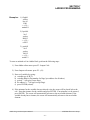
1.4 System Requirements
The SYSdev software package will run on any IBM PC or compatible with the following minimum
system requirements:
1)
2)
3)
4)
5)
DOS 3.1 or greater
640K RAM
Hard Disk
One 3.5" (720KB) or 5.25" (1.2MB) Diskette Drive
COM RS-232 Port
In addition to the above, an EPROM programmer capable of programming 2732A, 2764, and
27C256 EPROMs is required for EPROM program memory-based boards (S3010, S3012-EP,
S3021, and S3022). SYSdev can directly interface to the GTEK 7228 EPROM programmer using
the PGMX communications program (provided by GTEK). If another EPROM programmer is used,
the user will have to provide the appropriate communication software to interface with the EPROM
programmer.
________________________________________________________________________________
1.5 Installation
The SYSdev software package is provided on both 3.5" (720KB) and 5.25" (1.2MB) diskette
formats. Each format contains three disks. Both diskette sets contain the same files, use which ever
is appropriate for your system. The software package contains an installation program on disk #1 of
the three disks named INSTALL.EXE. The installation program creates the appropriate directories
on your hard drive and copies the executable files and support files from the diskettes to the
respective directories. For this reason, the installation program should always be used to install the
software on your hard disk and to back-up the software from the hard disk to diskettes.
The install program installs the SYSdev program from the drive it was invoked from to any user
designated drive (A,B,C,D,E,F). Thus, SYSdev can be installed from either diskette drive (A or B)
to any hard drive (C,D,E, or F) or can be backed up from any hard drive (C,D,E, or F) to either
diskette drive (A or B). The install program creates three directories at the root directory of the
designated drive called SYS51, SYS96, and PLS51 and copies the corresponding executive files to
these directories. In addition, two sub-directories are created called SUP51 and SUP96 in the
SYS51 and SYS96 directories respectively, with the corresponding support files copied to these
directories. The primary SYSdev.EXE executive shell file is copied to the root directory of the
designed drive along with INSTALL.EXE file.
SYSdev Program Development Manual
SYSTEMS Electronics Group
-4-
SECTION 1
INTRODUCTION
________________________________________________________________________________
1.5.1 Installing SYSdev on a Hard Disk
To install SYSdev on your hard disk, perform the following:
1) With the computer booted up and at the MS-DOS prompt, install the SYSdev disk #1 in the
diskette drive (A or B).
2) Switch to the diskette drive you installed disk #1 in (A or B) and type INSTALL and press
Enter.
3) The install program will prompt you for the drive that you want to install the SYSdev software
on. Enter the drive letter of the hard disk (C,D,E, or F) that you want SYSdev installed on and
press Enter.
4) The install program will then prompt you for the COM port number used for RS-232
communications to the target board. This is the COM port which will be used to interface with
the PROG and CHAN ports of the target board. COM ports 1,2,3,4,5,6 and 7 are supported.
Enter the COM port number and press Enter. If your computer has only one RS-232 COM port,
enter 1.
5) The install program will then install the SYSdev software package on the designated drive,
prompting for disks #2 and #3 when needed.
________________________________________________________________________________
1.5.2 Backing Up the SYSdev Software to a Diskette Drive
The install program can be used to backup the SYSdev software from a hard drive to a diskette
drive. The procedure is the same as installing the software, except that INSTALL is invoked from
the root directory of the hard drive that SYSdev is installed on (INSTALL.EXE was copied to the
hard drive when the SYSdev package was installed). When prompted for the drive to install
SYSdev on, enter the diskette drive you want to backup to. Install pre-formatted disks #1, #2, and
#3 when prompted by the install program.
SYSdev Program Development Manual
SYSTEMS Electronics Group
-5-
SECTION 1
INTRODUCTION
________________________________________________________________________________
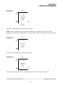
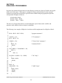
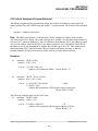
1.5.3 INSTALLING SYSdev UNDER WINDOWS
To install SYSdev under the Windows operating system, perform the following:
1) From the desktop task bar, select “Start”, “Programs” and select “MS-DOS Prompt”.
2) From the MS-DOS command prompt, switch to the root directory of the hard drive you want to
install the SYSdev software.
Example:
C:
cd\
<Enter>
<Enter>
3) Follow the instructions given in section 1.5.1. Once SYSdev has been successfully installed on
your hard drive, type “EXIT” at the MS-DOS command prompt to return to the Windows desk
top.
4) “Double-Click” on “My Computer”. Open the folder of the drive SYSdev was installed on.
5) Select the “SYSDEV.EXE” file with a single click of the left mouse button. Hold down the
mouse button and drag the file onto the desk top. Windows will setup a “Short Cut” to SYSdev.
6) The installation of SYSdev under Windows is now complete. Launch SYSdev by double
clicking on the icon to verify proper operation.
________________________________________________________________________________
1.6 Running SYSdev
Once installed on your hard drive, SYSdev is invoked by performing the following:
1) Switch to the root directory of the hard drive SYSdev was installed on.
2) Type SYSDEV and then press Enter.
3) The SYSdev shell will be invoked, displaying the shell menu. See section 2 for details on the
shell commands.
SYSdev Program Development Manual
SYSTEMS Electronics Group
-6-
SECTION 2
SYSDEV SHELL
The SYSdev shell is used to organize the user directories, create and edit user program files, select
the target board for the user program, and automatically invoke the appropriate SYSdev51,
SYSdev96, or PLSdev program based on the selected target board. Sub-directories should be used
to store and organize the user programs. This is desirable both from the standpoint of better user file
management and from the standpoint of program execution speed. The more files located in one
directory, the slower the access time to the user files will be. Thus, by storing user programs in
different directories that have a logical meaning to the user, and thus a better file organization, the
speed of execution of the SYSdev program is also enhanced. The maximum number of programs
allowed in one directory is 30. The maximum number of sub-directories in one directory is 120. Of
course by making sub-directories within sub-directories, no actual limit is placed on the number of
user programs which can be stored on one hard drive (other than the actual amount of memory on
the hard drive). These sub-directories can be created using the "F5: Make Dir" command in the
SYSdev shell.
________________________________________________________________________________
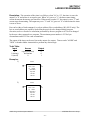
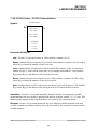
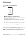
2.1 SYSdev Shell Menu
The SYSdev shell consists of a menu which displays the selected program name, current directory,
target board along with fields that display the existing program selections available for editing,
available directories, and possible target boards. The definitions of these fields are as follows:
PROMPT: This is a field which displays various prompts to the user based on the selected
command, informing the user what to do.
DIR: This field displays the currently selected drive and directory. This is used as the path to the
user program name when creating or editing a program and is set using the "F6: Select Drive" and
"F3: Select Dir" commands. When SYSdev is initially invoked, this is set to the root directory of
the current drive.
PROG: This is the program currently pointed to by the selection arrow in the Program Selections
field of the menu. This field is also used to enter the name of the user program when the "F1: Create
Prog" command is executed.
TARGET BOARD: This field displays the target board for the currently selected program. The
target board is selected when the "F1: Create Prog" command is selected. Once set, the target board
cannot be changed for a specific user program.
PROGRAM SELECTIONS: This field contains a list of the existing user programs in the
currently selected directory. The currently selected program is the program pointed to by the
selection arrow. The selection arrow can be moved to any displayed program using the Left, Right,
Up and Down arrow keys. When SYSdev is initially invoked, this displays all the SYSdev user
programs in the root directory of the current drive.
SYSdev Program Development Manual
SYSTEMS Electronics Group
-7-
SECTION 2
SYSDEV SHELL
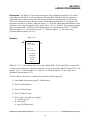
SUB-DIRECTORY SELECTIONS: This field contains a list of the existing sub-directories in the
currently selected directory (these would be sub-directories within the parent directory). The “F3:
Select Dir” command is used to select one of these directories as the current directory. When
initially invoked, this displays all the sub-directories in the root of the current drive (whether they
contain SYSdev user programs or not).
TARGET BOARD SELECTIONS: This field contains a list of the target board selections
available for program development or timing channel set-point programming. This is selected when
the "F1: Create Prog" command is executed.
________________________________________________________________________________
2.2 SYSdev Shell Commands
The shell contains numerous commands for creating and editing the user program, selecting the
directory and drive the user programs are stored in, and executing DOS commands such as backup,
copy, delete, etc. from within the shell. The definitions of these commands are as follows:
F1: Create Prog
This command is used to create a new user program. When selected, the menu will prompt for
the program name. Enter the new name in the "PROG:" field of the menu using the valid MSDOS file name character set. The program name can be a maximum of eight characters in
length (no extension should be entered). Press ENTER to accept the program name. The shell
will then prompt you to select the target board. Use the select arrow to select the desired target
board, then press Enter.
Note: Once the target board is selected for a particular program, it cannot be changed.
The shell will now invoke either SYSdev51, SYSdev96, or PLSdev depending on the target
board selected.
Note: The M4020 PLC section is programmed with SYSdev51 and the PLS section is
programmed with PLSdev. The target board selection menu thus contains two selections for
the M4020: "M4020(PLC)" for the PLC section and "M4020(PLS)" for the PLS section. For
new programs, both SYSdev and PLSdev will prompt that the program does not exist and
whether it should be created. Answer "yes" and proceed with the corresponding configuration
menu.
F2: Set Colors
This selection allows the user to select the foreground color (characters) and background color
on PC's equipped with color monitors. Any of 16 foreground colors can be selected and any of
8 background colors.
SYSdev Program Development Manual
SYSTEMS Electronics Group
-8-
SECTION 2
SYSDEV SHELL
F3: Select Dir
This is used to select, as the current directory, one of the directories available in the subdirectories menu.
Note: Only directories within the current sub-directory are displayed and are available for
selection. Pressing "F3" positions the selection arrow in the sub-directories menu.
Position the selection arrow at the desired sub-directory and press ENTER. The "DIR:" field
will be updated to show the newly selected directory while the program selections menu will
be updated to show the existing user programs in the selected directory. The sub-directories
menu will also show the sub-directories that exist in the selected directory.
Note: The "F4: Root Dir" command must be used to back out of the currently selected
directory and return to the root directory of the currently selected drive.
F4: Root Dir
Used to set "DIR:" to the root directory of the selected drive. This command is primarily used
to back out of previously selected directories if it is desired to change to a directory that is not
a sub-directory of the current directory. Pressing "F4" will set "DIR:" to the root directory and
display the user programs and directories in the root directory of the selected drive.
F5: Make Dir
This selection creates a new sub-directory in the currently selected directory. When selected,
the menu will prompt for the directory name. Enter the new name using the valid MS-DOS
directory name character set. The directory name can be a maximum of eight characters in
length. Press ENTER to accept the directory name. The new directory will now be displayed
in the sub-directories selection menu and can now be selected as the current directory using
the "F3: Select Dir" command if desired.
F6: Select Drive
This selection is used to change the currently selected drive. When selected, the shell prompts
for the drive letter (A,B,C,D,E, or F). Enter the new drive and press ENTER. The "DIR:" field
will be changed to the root directory of the new drive and the existing SYSdev user programs
and sub-directories in the new drive root directory will be displayed.
F7: Copy Prog
Used to copy the selected program to a new program name in the current directory. Enter the
new name using the valid MS-DOS file name character set. The program name can be a
maximum of eight characters in length (no extension should be entered). Press ENTER to
accept the program name that the selected program will be copied to. The new program will
then be displayed in the program selections menu.
SYSdev Program Development Manual
SYSTEMS Electronics Group
-9-
SECTION 2
SYSDEV SHELL
F8: Backup Prog
This selection is used to backup the selected program to the root directory of a user specified
diskette drive. When selected, the shell prompts for the drive (A or B) that the program will
be backed up to. Enter the drive and press ENTER. The currently selected program will be
copied to the root directory of the specified diskette.
F9: Restore Prog
This selection is used to restore a previously backed up program from the root directory of a
user specified drive to the currently selected directory and program. When selected, the shell
prompts for the diskette drive (A or B) that the program will be copied from. Enter the drive
and press ENTER. The program, with the same name as the currently selected program, will
be copied from the root directory of the specified drive to the currently selected directory and
program name.
F10: Delete Prog
This selection deletes the currently selected program from the current directory. When
selected, the shell prompts one time to verify that the program is to be deleted, answer "y" to
delete, "n" to abort. If yes, the program is deleted from the program selections menu.
SYSdev Program Development Manual
SYSTEMS Electronics Group
- 10 -
SECTION 3
MENUS
The following sections are a description of the various SYSdev menus. In general, the PgUp, PgDn,
Home, End, and cursor left, right, up, and down keys all function as defined. Use these to move
from block to block within the program.
________________________________________________________________________________
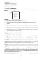
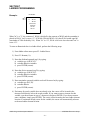
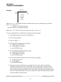
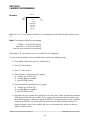
3.1 Main Development Menu
1: On-line Monitoring
Used to monitor, on-line, the state of variables during user program execution. Prior to
selecting this selection, an RS-232 cable should be connected from the COM port on the
computer to the PROG port on the target board. When selected, the first block of the main
program is initially displayed and communications with the target board is initiated. If
communications cannot be established, a message is displayed stating this. If communications is
established, the current status of the variables in block one are displayed in the program (for
ladder blocks). See section 12 for complete details on On-line functions.
2: Off-line Programming
Used to create and edit the user program files. When selected, block one of the main program is
displayed. If the program is a new program and the main program file does not exist, a prompt
will be displayed that asks whether the file should be created or not. Answer "y" to create the
main file. If the file already exists or is created, the Main Editor menu is displayed along with
the first block of the program. See Main Editor menu, section 3.2.
Note: Whenever a program change is made, the program must be re-compiled and downloaded
into the target board.
3: Edit System Configuration
This activates the System Configuration menu. See section 5. When SYSdev is initially invoked
and the program name entered does not exist, the System Configuration menu is automatically
activated. This selection allows the user to modify the system configuration at any time.
4: Print Program
This activates the program printout utilities. See section 11 for details of the printouts generated
and the print options available.
SYSdev Program Development Manual
SYSTEMS Electronics Group
- 11 -
SECTION 3
MENUS
5: Compile Program
This selection invokes the SYSdev compiler. Once a program is entered, it must then be
compiled before it can be downloaded to the target board or programmed into EPROMs. The
compilation process is a totally automated process requiring no further input from the user once
it is initiated. The compiler converts the user program into a HEX file that is downloaded to the
target board or programmed into the EPROM(s) which are installed in the target board.
Note: Whenever a program change is made, the program must be re-compiled prior to
downloading or programming new EPROMs.
The compiler performs the following steps:
1) The compiler performs a complete error check on all the files prior to actually compiling the
program. If any errors are detected, the compiler stops, displays the errors (see error codes
in appendix A), and prompts for exit.
If any files that are specified in the system configuration (timed interrupt or CO-CPU comm
interrupt) do not exist, or if any user function files called from any of the other files do not
exist, a message is displayed stating that the file could not be found along with the file
name. The compiler will stop and prompt for exit.
If either the timed interrupt or CO-CPU comm interrupt file exists but is not enabled in the
system configuration, a Warning message is displayed stating the file exists but is not
enabled. This is not an error and will not stop the compiler from compiling the program. The
message is provided simply to warn the user that the interrupt file was not included in the
compiled program and will not be active when the program is run on the board.
2) If no errors were detected, the compiler will then compile the program, converting the ladder
and high level blocks to the equivalent assembly instructions. These instructions are saved
in an assembly source file with the extension *.ASM. When the compilation is complete, the
address the stack is initialized to is displayed.
3) Next the Assembler is invoked. This converts the assembly instructions in the *.ASM file
created above to machine level instructions which can be executed by the processor. These
instructions are saved in a hex file with the extension *.HEX. This file is the file actually
downloaded to the board or programmed into EPROMs when the EPROM programmer is
invoked.
SYSdev Program Development Manual
SYSTEMS Electronics Group
- 12 -
SECTION 3
MENUS
4) Once the assembly is complete, the HEX file is verified for any assembly errors. If any are
found, they are displayed along with a message indicating that the HEX file was not created.
If an assembly error is found, the HEX file is erased. A file, with the name "assem.lst", is
created for viewing the errors detected. This file contains the assembly instructions along
with the error messages. This is a text file that can be viewed with a text editor or by using
the MS-DOS "type" command.
If no assembly error is found, a message stating that the program was assembled and
converted to hex is displayed. A prompt to exit back to the main menu is also displayed. The
program is now ready to be downloaded or programmed into EPROMs.
6: Target Board Interface
This selection invokes the Target Board Interface menu. This is used to download program and
data to the target board, upload data from the target board, view the target board fault codes if a
fault has occurred, set the S3000 serial network address, view the current program ident and
revision loaded in the target board and initiate the target board hardware confidence test. See
section 3.5 for more details.
7. Edit Variable Names
This selection brings up the variable names editor. This allows the user to enter the 3 lines by 7
character variable names for each variable. This is an alternative way of annotating variables
outside of the program editor. See section 10.1 for details on variable annotation.
8. Print Compile Errors
This selection is used to print the errors detected when the program is compiled. The errors
printed are the same errors displayed during the error check phase of program compilation. See
appendix A for descriptions of the error codes. This feature uses the MS-DOS "print" command
to print the errors. Your system autoexec batch file must contain a path to the directory that
PRINT.EXE is located in or you must copy PRINT.EXE into the "sys51" or "sys96" directory in
order for the SYSdev program to have access to the "print" command.
SYSdev Program Development Manual
SYSTEMS Electronics Group
- 13 -
SECTION 3
MENUS
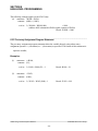
9. File Utilities
The SYSdev program allows you to back-up, restore, make a new directory, and to copy the
current program to another program name all while inside the SYSdev program. Selecting File
Utilities brings up a sub-menu with the following choices:
1: Back-up Program
This allows the current program to be backed up on a diskette in drive A:. Install the backup diskette in drive A: and press any key when ready. This copies all the files associated
with the program to the root directory of the A: drive.
Note: The files will be stored at the root directory of the diskette, not within a subdirectory. This selection provides a convenient way to back-up your program.
2: Restore Program
This copies the current program name from the root directory of the A: drive to the drive
and directory specified with the current program name. Install the diskette with the program
on it in the A: drive and press any key when ready. This copies all the files associated with
the program name on the A: drive to the path specified with the program name.
Note: The program files on the diskette in drive A: must be at the root directory. This
selection, along with the back-up selection above, provides a convenient way to copy
programs from one computer to another.
3: Make New Directory
This provides a way to make a new user program directory while inside SYSdev. Enter the
drive and directory name following the MS-DOS conventions of directory names.
4: Copy Program to Another Program Name
This provides a way to copy the current program name to any disk and directory while also
allowing the user to copy to a different program name. Enter the drive, directory, and new
program name using the MS-DOS conventions for directory and file names. Do not enter an
extension with the program name. This copies all the files associated with the program to the
different directory and program name. This selection can be used to copy the current name
to another drive and directory (when the program name entered is the same as the current
program name). This is also used to copy the program to a new program name. For instance,
when one program is similar to another completed program, simply copy the old program to
the new program name and edit as required.
SYSdev Program Development Manual
SYSTEMS Electronics Group
- 14 -
SECTION 3
MENUS
________________________________________________________________________________
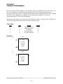
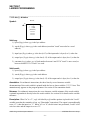
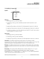
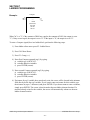
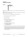
3.2 Main Editor Menu
The Main Editor menu is displayed as function key selections at the bottom of the screen along with
the program. This is brought up when the Off-line Programming selection from the Main
Development menu is made and after the appropriate file is selected. The following is the function
of each selection.
F1: Help Screen
This brings up the Editor Help menu. Help is available on the following subjects: Editor Menu
definitions, Ladder Box instructions, High level sfuncs, variable documentation, typical
program structure.
The help screens are text files, one 80 column by 112 line file per screen, which can be
customized by the user using any text editor. The help screens are located in the
SYS96\HELP directory for the S3012 and in the SYS51\HELP directory for all other boards.
The following file names are used for the respective screens:
EDITOR1.HLP - Editor Menu Definitions
EDITOR2.HLP - Ladder Box Instruction Definitions
EDITOR3.HLP - High Level Communications sfuncs
EDITOR4.HLP - High-Level General Purpose sfuncs
EDITOR5.HLP - Variable Documentation
EDITOR6.HLP - Typical Program Structure
ONLINE1.HLP - On-line Monitoring Help Screen
ONLINE2.HLP - Status Table Help Screen
F2: Insert Ladder
Insert Ladder is used to insert a ladder block at the block following the current block
displayed. For instance, if F2 is pressed while block 5 is displayed, the new ladder block will
be inserted at block 6. All the following blocks are moved to the next highest block number.
When F2 is selected, the block is added and the ladder editor is initiated. See ladder editor
section 3.3. Ladder instructions can then be entered into the block. See section 7 for details on
programming in ladder.
F3: Insert High
Insert High is used to insert a High-level block following the block that is currently displayed.
All the following blocks are moved to the next highest block number. When F3 is selected, the
block is added and the text editor is initiated. See text editor section 3.4. High-level
instructions can then be entered as text into the block. See section 8 for details on the Highlevel programming language.
SYSdev Program Development Manual
SYSTEMS Electronics Group
- 15 -
SECTION 3
MENUS
F4: Edit Block
Edit block is used to edit the current existing block. The appropriate editor is initiated
depending on the block type. The ladder editor is initiated if the block is a ladder block, the
text editor is initiated if the block is an assembly or High-level block.
F5: Search Func
Search Func is used to either move to a specified block number or to search out all the
occurrences of a variable within the current file. The following choices are available when F5:
Search Func is selected:
F1: Search block
When F1: Search block is selected, the cursor moves to the "block:" prompt. Enter the
block number you wish to move to and press Enter <CR>. If the block exists in the file,
it will be displayed, if not, the message "not found" will be displayed in the status field.
F2: Search Var
When F2: Search Var is selected, the cursor will move to the "var:" prompt. Enter the
variable by typing the variable type letter and address as it would be entered in the
program followed by Enter <CR>. The variable will then be searched for starting in the
current block. The program will be searched until the last block is reached, at that time
searching will continue from the first block until the current block is reached. If the
variable is found, the block containing the variable will be displayed with the cursor
positioned at the variable. If the variable is not found, the message "not found" will be
displayed in the status field. To continue searching for more occurrences of the same
variable, simply select F2: Search Var and then press Enter <CR>.
Note: Only the current file is searched, occurrences of the variable in other file types
(timed interrupt, user functions, etc.) is not detected.
Press "ESC" to return to the main editor menu.
F6: Cut Block
Cut Block cuts or deletes the current block from the file and saves it in a temporary buffer.
The blocks following the block that was cut are all moved to the next lowest block number.
Cut Block can be used in conjunction with Paste Block to move or duplicate blocks within the
file. Cut Block is also used to delete blocks from the file.
Note: Only one block can be cut at a time, any block that was in the temporary buffer when
the block was cut is lost when another block is cut.
Cut Block can be used on any block type (Ladder, High-level, or Assembly).
SYSdev Program Development Manual
SYSTEMS Electronics Group
- 16 -
SECTION 3
MENUS
F7: Paste Block
Paste Block pastes or inserts the block that was previously cut (and stored in the temporary
buffer) at the location following the currently displayed block. All the blocks following the
pasted block are moved to the next highest number. Paste Block must always be used in
conjunction with Cut Block.
Cut Block is used to cut the block desired while Paste Block is used to paste the block back in
at a new location. Paste Block is used to move a block to a different location or make
duplicate copies of a block in the file.
Paste Block can be used on any block type (Ladder, High-level, or Assembly). Paste block
cannot be used to move a block from one file to another file (i.e. moving a block from the
main program file to the timed interrupt file).
F8: Edit Doc
Edit Doc is used to enter the documentation associated with the currently displayed block.
When selected, the text editor is initiated in document mode. Up to 57 lines by 80 characters
of documentation can be entered for each block. This text is not executed as code, but is
displayed above the block on the program printout. This is where the inter-program
documentation is entered. See section 10.2 for more details.
F9: Select File
This selection displays a menu that allows the user to create or edit any of the following file
types:
F1:
F2:
F3:
F4:
F5:
Main Prog
Timed Intrpt
Comm Intrpt
User Func
Init Prog
-
Main program file
Timed Interrupt file
CO-CPU Communications Interrupt
User Function files
Initialization File
Select the file to be created or edited. If the file does not exist, a prompt will be displayed that
asks whether the file is to be created or not. If you want to create the file, answer "y", if not,
answer "n". If the file already exists or is created, the Main Editor menu is displayed again
along with the first block of the selected file.
F10: Save File
Save File saves the current file on the drive and directory specified with the program name. It
is necessary to save the file if any changes were made prior to exiting the ladder/text editor. If
the file was not saved, a prompt will be displayed asking if you want to save the file or not,
answer accordingly. When F10: Save File is selected, the file is saved and then control is
passed back to the main editor menu.
SYSdev Program Development Manual
SYSTEMS Electronics Group
- 17 -
SECTION 3
MENUS
F12: Insert ASM (Not shown on menu)
Insert ASM is used to insert an assembly block following the block that is currently displayed.
All the following blocks are moved to the next highest block number. When F12 is selected,
the block is added and the text editor is initiated. See text editor, section 3.4. Assembly
instructions are then entered as text into the block. See section 9 for details on programming
in assembly.
SYSdev Program Development Manual
SYSTEMS Electronics Group
- 18 -
SECTION 3
MENUS
________________________________________________________________________________
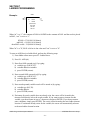
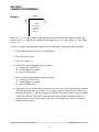
3.3 Ladder Editor Menu
The Ladder Editor is executed when either Insert Ladder or Edit Block (while the current block is a
ladder block) is selected. The following choices are available from the Ladder Editor menu:
F1: -] [- Normally Open Contact
This selection is used to enter a normally open contact. See section 7.1.1.
F2: -]/[- Normally Closed Contact
This selection is used to enter a normally closed contact. See section 7.1.2.
F3: Output Coils
This selection brings up the output coils menu. The choices from this menu are:
F1: -( )F2: -(L)F3: -(U)F4: -(/)-
standard coil
latch coil
unlatch coil
invert coil
See sections 7.1.3 thru 7.1.6 for more details on output coils.
F4: Timers/Count
This selection brings up the timers/counter menu. The choices from this menu are:
F1: Timer (scan time base)
F2: Timer (0.01 second time base)
F3: Timer (0.10 second time base)
F4: Timer (1.00 second time base)
F5: Counter
See sections 7.1.7 and 7.1.8 for more details on timers and counters.
SYSdev Program Development Manual
SYSTEMS Electronics Group
- 19 -
SECTION 3
MENUS
F5: Ladder Boxes
This selection allows the user to enter any of the following ladder box instructions:
F1:
F2:
F3:
F4:
F5:
F6:
F7:
F8:
F9:
F10:
add (+)
subb (-)
mul (*)
div (/)
remain (%)
AND (&)
OR (|)
XOR (^)
Shift Reg
More Boxes
F1: shift (>>)
F2: shift (<<)
F3: comp (==)
F4: comp (>)
F5: comp (>=)
F6: move move into
F7: move invert
F8: move (ext)
F9: call ufunc
F10: More Boxes
F1: netwrk comm
F2: CO-CPU comm
F3: Block comm
addition
subtraction
multiply
division
remainder of division
bitwise AND
bitwise OR
bitwise exclusive OR
Shift register
shift right
shift left
compare (equal)
compare (greater than)
compare (greater than or equal)
invert and move into
move into external address
call user function (0-99)
serial network communications
CO-CPU communications
CO-CPU block communications
See section 7 for more details on these instructions.
F6: Var Names
This selection is used to enter variable documentation while inside the Ladder Editor. This
feature makes it easy to annotate a program while it is being created or edited. See section
10.1 for more details on variable annotation entry.
F7: ——— (horizontal short)
This selection is used to enter a horizontal short in a ladder block. All ladder instructions must
be connected to form the network desired. The horizontal short is a fundamental element
required to make these connections. The horizontal short is entered with the left node at the
current cursor location and the right node at the next (to the right) element location.
SYSdev Program Development Manual
SYSTEMS Electronics Group
- 20 -
SECTION 3
MENUS
F8: | (vertical short)
This selection is used to enter a vertical short in a ladder block. The vertical short is a
fundamental element required to build networks or rungs in a ladder block. The vertical short
is entered with the top of the short at the current cursor location and the bottom of the short at
the next lower row.
F9: Vert Open
This selection is used to delete vertical shorts. To delete the short, place the cursor at the top
node of the vertical short and press F9. The vertical short will be deleted while the instruction
at the cursor location is left unchanged.
F10: Delete Elem
This selection is used to delete the instruction at the current cursor location. The instruction
will be immediately deleted when F10 is pressed. The instruction to the right of the cursor will
be deleted.
ESC: Escape
The escape key is used to terminate the Ladder Editor and return to the Main Editor menu.
The ladder block will be accepted exactly as left when "ESC" is pressed.
________________________________________________________________________________
3.3.1 Operation of Ladder Editor
When the Ladder Editor is initiated, the cursor appears in the first element position of the ladder
block matrix (row 0, column 0). Instructions are entered at the current cursor position with the left
node of the instruction at the cursor location and body of instruction to the right. The cursor can be
moved to various element positions within the block using the left, right, up, and down arrow keys,
the PgUp, PgDn, Home, and End keys. Once all instructions are entered as desired, press ESC to
accept the block and return to the Main Editor menu.
The status field on the left side of the screen simply displays messages such as "top of file", "bot of
file", etc.
SYSdev Program Development Manual
SYSTEMS Electronics Group
- 21 -
SECTION 3
MENUS
________________________________________________________________________________
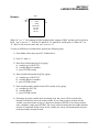
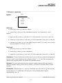
3.4 Text Editor Menu
The Text Editor is activated when Insert ASM, Insert High, or Edit Doc is selected. The Text Editor
allows the entry of Assembly or High-level instructions in the respective block type as well as the
documentation for each block. The following fields can be found in the text editor menu:
Block:
Current block number of block being edited.
Page:
Page number within block. Each block has up to three pages (19 lines per page).
Type:
Block type. Assembly, High-level, or Document.
Status: Status messages such as "top of block" when at line 0, "bottom of block" when at line 56.
Mode:
Overwrite or Insert. When in overwrite (default mode), text is entered over existing text
when typed in. When in insert, text is inserted into the block, moving the existing text
right and down as necessary.
Line:
Current line number of cursor. Lines are numbered from 0 (top) to 56 (bottom).
Col:
Current column number of cursor. Columns are numbered from 0 (left) to 79 (right).
In addition to the status fields listed above, a number of function key selections are also available
while in the Text Editor. These are:
F8: Var Names
This selection is used to enter variable names while inside the Text Editor. This feature makes
it easy to annotate a program while it is being created or edited. See section 10.1 for more
details on variable annotation entry.
F9: Cut Line
This selection cuts the current line that the cursor is on and stores it in a temporary buffer. All
the lines following the cut line location are moved up one line. This feature is used to delete
lines or, when used in conjunction with Paste Line, to copy a line to a new location or make
duplicates of a line. Only one line can be cut and pasted at a time. When a line is cut, the
previous line cut is lost.
SYSdev Program Development Manual
SYSTEMS Electronics Group
- 22 -
SECTION 3
MENUS
F10: Paste Line
This selection is used to paste the line in the temporary line buffer at the current cursor line
location. All the lines following the paste location are moved down one line. Paste is always
used in conjunction with Cut Line. First the line is cut and then pasted at the new location.
Paste can also be used to make duplicates of a line, simply press F10: paste line the number of
times the line is to be duplicated.
ESC: Escape
The escape key is used to terminate the Text Editor and return to the Main Editor menu. The
text block will be accepted exactly as left when "ESC" is pressed.
________________________________________________________________________________
3.4.1 Operation of Text Editor
When the Text Editor is initiated, the cursor is located in the upper left corner of the screen. Text is
entered at the current cursor location. The space, backspace, tab, return, and delete keys all work as
defined. The cursor can be moved within the block using the left, right, up, and down arrow keys,
and the PgUp, PgDn, Home, and End keys. The Ins key is used to toggle between the overwrite and
insert mode. When in overwrite mode, text is typed in over any existing text. When in insert mode,
the text is inserted, moving any existing text right and down as necessary. Once all text is entered as
desired, press ESC to accept the block and return to the Main Editor menu.
3.5 Target Board Interface Menu
SYSdev Program Development Manual
SYSTEMS Electronics Group
- 23 -
SECTION 3
MENUS
________________________________________________________________________________
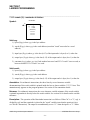
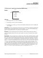
3.5 Target Board Interface Menu
1: Download program to target board
This selection is used to download the HEX file created when the user program is compiled, to
the board which will run the program. This is done on all battery-backed program memory
boards such as the S3012-BR, S3016, S3014, all M4000 and D4110. To download the program,
perform the following:
WARNING: Program execution of the target board is suspended during program
download. Thus, the process controlled by the target board must be stopped during the
program download.
1) Connect COM1 on the computer running SYSdev, to the PROG PORT on the target board
to be loaded with the program, using the appropriate RS-232 cable (see target board user's
manual).
2) With both the computer and target board powered up, select this selection from the Target
Board Interface menu. A prompt will appear to verify whether to continue or not. To abort
the download, press "ESC", otherwise, press any key to start the download.
3) While the download is in progress, the HEX address of the current program byte being sent
to the target board is displayed and the "RUN" LED on the target board will flash. Program
execution in the target board is suspended during program download.
4) The target board will reset once the entire program has been sent and start execution of the
user program in the same manner as a power on reset. A program download complete
message will be displayed along with a prompt to return to the Target Board Interface menu.
Press any key to return to the menu.
5) If the computer was unable to initiate the program download to the target board, a message
stating this will be displayed. Verify the RS-232 cable connections between COM1 on the
computer and the PROG PORT on the target board for proper connection. Also verify that
the RS-232 cable is wired correctly (see target board user's manual). Press any key to return
to the Target Board Interface menu and try the download again.
SYSdev Program Development Manual
SYSTEMS Electronics Group
- 24 -
SECTION 3
MENUS
2: Download data to target board
This selection is used to download the data file to the target board. This file contains data from a
previous data upload from the target board. The data download occurs concurrently with
program execution. To download the data file, perform the following:
1) Connect COM1 on the computer running SYSdev, to the PROG PORT on the target board
to be loaded with the data, using the appropriate RS-232 cable (see target board user's
manual).
2) With both the computer and target board powered up, select this selection from the Target
Board Interface menu. A prompt will appear to verify whether to continue or not. To abort
the download, press "ESC", otherwise, press any key to start the download.
3) While the download is in progress, the HEX address of the current data byte being sent to
the target board is displayed. Program execution in the target board continues concurrently
with the data download.
4) Once data download is complete, a data download complete message will be displayed
along with a prompt for return to the Target Board Interface menu. Press any key to return to
the menu.
5) If the computer was unable to initiate the data download to the target board, a message
stating this will be displayed. Verify the RS-232 cable connections between COM1 on the
computer and the PROG PORT on the target board for proper connection. Also verify that
the RS-232 cable is wired correctly (see target board user's manual). Press any key to return
to the Target Board Interface menu and try the download again.
SYSdev Program Development Manual
SYSTEMS Electronics Group
- 25 -
SECTION 3
MENUS
3: Upload data from target board
This selection is used to upload the data from the target board to the data file on disk. This
allows presets and other user variables to be saved from the target board for download to other
target boards or download at a later time. The data upload occurs concurrently with program
execution. To upload the data from the target board, perform the following:
1) Connect COM1 on the computer running SYSdev, to the PROG PORT on the target board
to be uploaded from, using the appropriate RS-232 cable (see target board user's manual).
2) With both the computer and target board powered up, select this selection from the Target
Board Interface menu. A prompt will appear to verify whether to continue or not. To abort
the upload, press "ESC", otherwise, press any key to start the upload.
3) While the upload is in progress, the hex address of the current data byte being received from
the target board is displayed. Program execution in the target board continues concurrently
with the data upload.
4) Once the data upload is complete, a data upload complete message will be displayed along
with a prompt for return to the Target Board Interface menu. Press any key to return to the
menu.
5) If the computer was unable to initiate the data upload to the target board, a message stating
this will be displayed. Verify the RS-232 cable connections between COM1 on the computer
and the PROG PORT on the target board for proper connection. Also verify that the RS-232
cable is wired correctly (see target board user's manual). Press any key to return to the
Target Board Interface menu and try the upload again.
4: Target board Fault codes/status
This selection is used to view the target board fault codes, if any have occurred. See the
respective target board user's manual for a complete list of possible fault codes and procedures
for viewing the fault codes.
5: Target board Network address
This selection is used to set the S3000 serial network for the respective target board. This is
only done for S3000 boards/M4000 modules actually connected to the S3000 serial network.
See the respective target board user's manual for more details on the S3000 serial network and
the procedure for setting the network addresses.
SYSdev Program Development Manual
SYSTEMS Electronics Group
- 26 -
SECTION 3
MENUS
6: Current target board program Ident/Revision
This is used to display the program ident and revision of both the target board and currently
selected program. The program ident is simply the name of the program file. The program
revision is set initially to 1 when a program is first created and then incremented once every
time the program is compiled.
The purpose of the program ident and revision is to verify that the program monitored with
SYSdev, during online monitoring, is actually the same program and revision running in the
target board which is being monitored. When the online monitor is invoked, the program ident
and revision is read from the target board and compared to the currently selected program. If the
two are not equal, a prompt is displayed notifying the user that the two are not equal, thus
preventing the unintentional monitoring of a target board which is actually running a different
program or different revision of the same program. See section 12.2.
This selection actually displays both the target boards program ident/revision as well as the
selected program's ident/revision. This then provides a mechanism to determine what program
and revision level is actually loaded in a specific target board.
7: Target board Hardware Confidence Test
This selection is used to invoke the hardware confidence test for a particular target board. When
selected, a list of target boards is displayed. Select the board to be tested and then proceed with
the test. See the respective target board user's manual for a complete description of the target
board's hardware confidence test and procedure for performing the test.
8: Set time and date in target board
This selection allows the user to set the time and date in boards equipped with a real time clock
(S3016 and D4110). When this selection is selected, the current time and date is read from the
board and displayed. The user is then prompted to enter the current time (in 24 hour military
time). When the time is entered, the current date is then prompted for. Enter the date in MonthDay-Year format.
SYSdev Program Development Manual
SYSTEMS Electronics Group
- 27 -
SECTION 3
MENUS
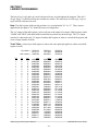
9: Program EPROM
Once the program is compiled without errors, this selection is used to program the EPROM(s)
on target boards equipped with EPROM program memory. If the program has not been
compiled, a message stating that the HEX file does not exist will be displayed. Return to the
main menu and compile the program, then try programming the EPROM again. The S3010 uses
2732A EPROMs while the S3021 and S3022 use 2764 EPROMs and the S3012-EP uses
27C256 EPROMs. Make sure the EPROMs are fully erased (using a UV light eraser) prior to
programming the EPROMs.
This EPROM programming facility supports the GTEK 7228 EPROM programmer using the
PGMX communications program. The PGMX.COM program must be in the "sys51" or "sys96"
directory for this facility to work (the "install" program will load PGMX in the "sys51" or
"sys96" directory provided PGMX was purchased with SYSdev). If PGMX is not present, a
message stating this will be displayed along with a prompt to exit back to the main menu. When
using another EPROM programmer, the user will have to program the EPROM(s) outside of the
SYSdev program using the communications program supplied with that EPROM programmer.
Programming EPROM(s):
When using the GTEK EPROM programmer, follow the steps displayed once the facility is
initiated. The facility calculates the size of the HEX program and determines if it is too big for
the target board. If it is, a message stating this is displayed along with a prompt to exit back to
the main menu. The user program will have to be reduced in size if this is the case. When the
target board is an S3010, the facility also determines whether one or two EPROMs are required
based on the HEX file size. The S3010 program memory is a total of 8K implemented using two
4K 2732A EPROMs. If the program is less than 4K, only one EPROM is required. If the
program is greater than 4K, two EPROMs are required. The S3012-EP uses two 27C256
EPROMs programmed in split mode such that the first EPROM is programmed with all the even
bytes (low order bytes) while the second EPROM is programmed with all the odd bytes (high
order bytes). Follow the instructions displayed exactly when programming EPROMs for the
S3012-EP.
Install the EPROM in the programming socket of the EPROM programmer. If a 2732A EPROM
is to be programmed, place the chip in the bottom portion of the socket with pin 1 of the
EPROM in pin 3 of the socket. The upper pins of the socket are not used in this case. If a 2764
or 27C256 EPROM is to be programmed, place the chip in the socket with pin 1 of the chip in
pin 1 of the socket. Press any key to start the programming process. The programming socket
on the EPROM programmer is a zero force insertion socket, clamp the EPROM in the socket
before commencing programming.
SYSdev Program Development Manual
SYSTEMS Electronics Group
- 28 -
SECTION 3
MENUS
If the EPROM programmer is connected to the computer properly, the current address being
programmed is displayed. The "BUSY" LED on the EPROM programmer is also illuminated
while the EPROM is programmed. Follow the instructions displayed for the particular
EPROM(s) being programmed. When the EPROM programming is complete, a prompt to return
to the main menu will be displayed. Remove the EPROM from the socket and install in the
board.
For S3010s, the first EPROM programmed is installed in IC socket U4 (lower 4K) while the
second EPROM is installed in U5 (upper 4K) of the S3010. Refer to the respective user's
manual for more details on installing EPROM(s) in the S3010, S3012-EP, S3021, and S3022
boards.
EPROM Programming Problems:
If a message is displayed stating there is a hardware fault or that the EPROM programmer is not
responding, verify that the EPROM programmer is powered up and that the programmer cable
is connected properly. Press ESC and then any key to exit the EPROM programming facility
and then attempt programming the EPROM again. If the problem persists, try powering down
the EPROM programmer (remove EPROM from programmer before powering down), wait five
seconds and then power it back up and try again. If the problem still persists, check the EPROM
programming cable for continuity and proper pin connection on both connectors.
SYSdev Program Development Manual
SYSTEMS Electronics Group
- 29 -
SECTION 3
MENUS
(This Page Intentionally Left Blank)
SYSdev Program Development Manual
SYSTEMS Electronics Group
- 30 -
SECTION 4
OVERVIEW OF PROGRAM STRUCTURE AND LANGUAGE
________________________________________________________________________________
4.1 Program Structure and Execution
The typical SYSdev user program is constructed with up to five different file types. These are:
1)
2)
3)
4)
5)
Initialization file
Main Program file
Timed Interrupt file
CO-CPU Communications file
User Function files
These five file types, together with the internal overhead code generated by the compiler, constitute
the entire user program. The following is a description of the fundamental program execution as it
pertains to the main processor boards. The program execution of the intelligent I/O boards is
essentially the same with only very minor exceptions.
At power up, an internal initialization routine is entered which clears all the output boards, tests the
ram memory, initializes all the timers used in the program, and enables the timed interrupt and COCPU communications interrupt. At the end of this initialization, the user Initialization file is
executed, if one is present. This gives the user a chance to perform any logic desired at power up.
Once initialization is complete, the Main Program file is executed. This file is executed or scanned
from beginning to end continuously . At the beginning of the main program scan, all input boards
specified in the system configuration are read, and all output boards specified in the configuration
are written to.
The execution of the main program continues indefinitely unless either the Timed Interrupt or
Communications Interrupt occurs. The main program execution is suspended at the occurrence of
either interrupt, with program execution transferred to the corresponding interrupt file. The interrupt
file is then executed once, from beginning to end. At the completion of the interrupt, program
execution is passed back to the main program at the location that it was suspended.
The following is a description of each user file type and its use.
SYSdev Program Development Manual
SYSTEMS Electronics Group
- 31 -
SECTION 4
OVERVIEW OF PROGRAM STRUCTURE AND LANGUAGE
________________________________________________________________________________
4.1.1 Initialization file:
The Initialization file is executed once at power up. The purpose of this file is to give the user an
opportunity to execute any logic desired at power up, prior to the start of main program execution.
The primary use of this file is to perform the initial communications with any intelligent (CO-CPU)
I/O boards in the rack. All CO-CPU boards must be initialized at power up in order to set the board
identifier in each CO-CPU board. Another use of the Initialization file is to preset any other user
variables that would otherwise not be preset.
The Initialization file is optional. The user program does not have to incorporate this file.
________________________________________________________________________________
4.1.2 Main Program file:
The Main Program file is the primary user file. This file executes the majority of the user
application code. The Main Program file is executed (scanned) from beginning to end continuously.
The Main Program file is the only file that is required. All programs must have a main program
file.
________________________________________________________________________________
4.1.3 Timed Interrupt file:
The timed interrupt file is executed once every 0.250 to 65.000 milliseconds. The user specifies the
exact time, in this range, between timed interrupt executions. The primary application of the timed
interrupt is to perform high speed processing on a certain critical task of the user application. In this
situation, critical inputs can be read, logic can be performed based on these inputs, and then outputs
associated with the critical task can be updated prior to exiting the timed interrupt.
An example would be an application that required a task to be performed every 0.5msec or less. If
the main program scan was 3 to 4msec, a timed interrupt could be created to execute every 0.5msec.
The timed interrupt would then interrupt the main program six or more times during one scan,
allowing the critical task to be processed as required.
Another example of the timed interrupt use is an application that requires a task to be performed at
precise intervals. The main program scan time will vary depending on the code that is executed
each scan and on the true/false state of this code. The timed interrupt provides a means around this
by providing a file which is executed at precise intervals.
SYSdev Program Development Manual
SYSTEMS Electronics Group
- 32 -
SECTION 4
OVERVIEW OF PROGRAM STRUCTURE AND LANGUAGE
The only limitation on the use of the timed interrupt is that the execution time of the timed interrupt
file must be less than the timed interrupt time interval. If the timed interrupt execution time is
longer than the time interval, a watchdog time out may occur, causing the system fault routine to be
executed.
The timed interrupt file is optional, the user program does not have to incorporate this file.
________________________________________________________________________________
4.1.4 Communications Interrupt file:
The communications interrupt file is executed in response to a communications request from an
intelligent (CO-CPU) I/O board. This file is generally used to respond to the communications
request by decoding which CO-CPU board initiated the request, then performing the appropriate
communications system function (see section 8.10.5).
The communications interrupt file is not required.
________________________________________________________________________________
4.1.5 User Function files:
User function files are subroutines which can be called from any of the other files. Up to 100 user
functions can be defined. The functions are designated by number (i.e. ufunc01, ufunc20, etc.). The
user function is a true subroutine in that program execution is suspended in the file while execution
is passed to the user function. On return from the function, program execution continues at the
location in the file where it was suspended.
User functions can be called from any file type including another user function. Thus, user
functions can be nested within one another to any level desired. The only limitation is that recursion
is not allowed (a user function cannot call itself).
User functions are optional, the user program does not have to incorporate user functions.
SYSdev Program Development Manual
SYSTEMS Electronics Group
- 33 -
SECTION 4
OVERVIEW OF PROGRAM STRUCTURE AND LANGUAGE
________________________________________________________________________________
4.2 SYSdev Programming Language
Each of the five file types (Initialization, Main Program, Timed Interrupt, CO-CPU Comm
Interrupt, and User Function) are all implemented with the same instructions and file format. Each
file is implemented as a series of consecutive blocks where each block can be defined as one of
three programming languages: Ladder, High-level, or Assembly.
________________________________________________________________________________
4.2.1 Ladder Block:
The Ladder block is a matrix of 7 rows by 9 columns in which ladder instructions can be entered.
The Ladder instruction set consists of the following instructions:
1)
2)
3)
4)
5)
6)
Contacts (normally open and normally closed)
Coils (standard, latch, unlatch, invert)
Timers
Counters
Shift Registers
Ladder Box Instructions
The instructions are entered free form where the programmer simply makes the network or rung
"look" as desired. No specific order of entry is required. Virtually any network form can be entered
including nested "or" networks. As many networks or rungs that can fit in the block may be entered.
Within the block, the rungs are executed starting with the first rung down to the last rung. Within
each network, the network is executed from the coil (right) to the power rail (left). See section 7 for
an in-depth description of ladder programming.
________________________________________________________________________________
4.2.2 High-level Block:
The High-level programming language is a subset of the C programming language. The High-level
Block consists of a 57 line by 80 column matrix where the High-level instructions are entered as
text.
The High-level language incorporates the fundamental C statements such as: program statements,
"if else-if else" statements, "for", "while", and "do while" loops, "goto" statement as well as some
statements unique to the SYSdev programming language including user function calls ("ufuncXX")
and system function calls ("sfuncXX") which are used for I/O operations.
SYSdev Program Development Manual
SYSTEMS Electronics Group
- 34 -
SECTION 4
OVERVIEW OF PROGRAM STRUCTURE AND LANGUAGE
Within a High-level block, the instructions are executed sequentially with the exception of
conditional program statements and the unconditional jump ("goto") statement. See section 8 for an
in-depth description of the High-level programming language.
________________________________________________________________________________
4.2.3 Assembly Block:
The assembly language is the Intel MCS-51 assembly language for all boards except the S3012 and
the Intel MCS-96 language for the S3012. The instructions conform to the MCS-51 or MCS-96
instruction set while the syntax conforms to the UNIX system V assembler syntax.
The assembly block is a 57 line by 80 column matrix where the assembly instructions are entered as
text. The instructions are executed sequentially with the exception of the jump instructions. See
section 9 for more details on the Assembly instruction set.
Most programs do not require the use of assembly programming. The assembly language was
included to provide the more advanced user absolute flexibility and access to the respective
processor architecture.
Any file can have any number of each type of block. The blocks can be intermixed freely with one
another to create the desired program structure. Within a file, the blocks are executed sequentially,
starting with the first block of the file.
SYSdev Program Development Manual
SYSTEMS Electronics Group
- 35 -
SECTION 4
OVERVIEW OF PROGRAM STRUCTURE AND LANGUAGE
________________________________________________________________________________
4.3 SYSdev File Extensions
SYSdev creates a number of MS-DOS files associated with a particular user program. These
include the five file types discussed above plus additional internal files used by SYSdev. All files
use the user program name as the main file name and then add an extension for each different file
type.
The definition of each file extension follows where "name" is the user program name:
name.LIN:
name.LMN:
name.LTD:
name.LCM:
name.Lxx:
name.DOC:
name.LCF:
name.ERR:
name.LTL:
name.REV:
name.LDT:
name.NAM:
Initialization file.
Main Program file.
Timed Interrupt file.
CO-CPU Communications file.
User Function file where xx = user function number 00 to 99.
Variable Names Documentation file.
System Configuration file.
Compiler Error file.
Program Title file.
Program Ident/Revision
Data Download file
Variable Nicnames file
SYSdev Program Development Manual
SYSTEMS Electronics Group
- 36 -
SECTION 5
CONFIGURATION PARAMETERS
________________________________________________________________________________
5.1 Configuration Parameters
The system configuration is used to define the system or environment that the program will run in.
The different boards and modules in the S3000 and M4000 all have a wide range of different
configuration parameters which the user can specify. These include:
1)
Target Board: the board the program will be loaded into.
2)
Rack Size: used only by the S3012 to specify the number of slots in the I/O rack.
3)
I/O Slot Assignments: used by the S3012 to specify which boards will be in which slots.
4)
Timed Interrupt: used to enable the timed interrupt and set the time between interrupts.
5)
CO-CPU Communications Interrupt: used to enable the CO-CPU interrupt either in the main
processor board or CO-CPU board.
6)
USER PORT Baud Rate: used to set the baud rate of the USER PORT on certain boards.
7)
USER PORT Parity: used to set the parity of the USER PORT on certain board.
8)
USER PORT Stop Bits: used to set the number of stop bits on the USER PORT for certain
boards.
9)
Serial Network Baud Rate: used to set the baud rate on the serial network to 106KBPS,
229KBPS, or 344KBPS.
10) Input0 and Input1 Interrupt: used to enable the IN0 and IN1 interrupts on the M4000 and
D4110 modules.
11) Fixed Scan Time Mode: used to enable and set the time for fixed main scan time on the M4000
and D4110 modules.
Note: All the boards and modules use only a certain percent of the above configuration parameters.
In the System Configuration menu, SYSdev will only prompt the user for the parameters that apply
to the specific selected target board. Refer to the respective user's manual for details on the
configuration parameters that apply to the specific target board.
SYSdev Program Development Manual
SYSTEMS Electronics Group
- 37 -
SECTION 5
CONFIGURATION PARAMETERS
(This Page Intentionally Left Blank)
SYSdev Program Development Manual
SYSTEMS Electronics Group
- 38 -
SECTION 6
VARIABLE FORMATS
________________________________________________________________________________
6.1 Variables
Three classes of variables are used in the SYSdev programming language. They are: bits, bytes, and
words. Bits are a single bit in width and can have a value of 0 or 1. Bytes are 8 bits in width and can
have a value between 0 and 255 decimal or 0 and ffH hex. Words are 16 bits in width and can have
a value of 0 to 65535 decimal or 0 to ffffH hex.
Numbers used in variables and constants are unsigned integer values. No signed or floating point
numbers are allowed. Numbers can be represented as decimal or hex (see section 6.2 Constants).
Seven different variable types within these classes are available: flags (F), port pins (P), bytes (B),
inputs (X), timed interrupt inputs (I), outputs (Y) and words (W).
Note: Not all the target boards support the entire range of variable types. See the respective user's
manual for the target board for a complete description of the variable types supported for that
particular board and the number of variables available.
________________________________________________________________________________
6.1.1 Flags (F):
Flags are single bit variables which are generally used as internal coils or flags in the user program.
Flags can have a value of "0" or "1". For internal coils in ladder blocks and boolean logic in Highlevel blocks, flags provide the fastest execution times compared to any of the other variables.
The format of the flag variable as used in programming is:
Fzzz:
Where zzz is the three digit flag number.
Note: The leading 'F' must be a capital letter and that the flag number must be three digits (include
leading zeros as necessary).
Examples: F010, F056, F110, etc.
SYSdev Program Development Manual
SYSTEMS Electronics Group
- 39 -
SECTION 6
VARIABLE FORMATS
________________________________________________________________________________
6.1.2 Port Pins (P):
Port pins are single bit variables that map directly to specific hardware functions on the target
board. These can be input or output hardware functions as defined by the specific port pin. See the
respective user's manual for the target board for a complete description of the port pins functions.
The format for the port pins is:
Paa:
Where aa is the two digit port pin (10-17 or 30-37).
Note: The 'P' must be a capital letter and that the port pin address must be two digits.
Port pin variables are only accessible through the High-level or Assembly language. These
variables cannot be referenced with the ladder language. Port pin references are made identically as
to references to flags.
________________________________________________________________________________
6.1.3 Bytes (B):
Byte variables are 8 bit variables used as general purpose variables in the user program. Byte
variables can have a value between 0 and 255 decimal or 0 and ffH hex. Byte variables are used as
arithmetic variables in the High-level language, timer/counter presets and accumulators as well as
shift register bytes in the ladder language.
The format of the byte variable as used in programming is:
Bzzz:
Where zzz is the three digit byte address
Note: The leading 'B' must be a capital letter and that zzz must be a three digit number (include
leading zeros as necessary).
Examples: B080, B093, B151, etc.
SYSdev Program Development Manual
SYSTEMS Electronics Group
- 40 -
SECTION 6
VARIABLE FORMATS
Individual bits within the byte can also be accessed by simply appending a '.' followed by the bit
number (0-7) to the byte address. The form of this is:
Bzzz.y: Where zzz is the byte address as specified above and y is the bit (0-7).
This allows any bit in any byte to be referenced just as a flag is referenced. These byte.bit variables
can be used in ladder blocks as contact and coil variables as well as in High-level blocks. Execution
times for instructions that use bits within a byte are longer than execution times for instructions
using flags. Keep this in mind when using byte.bit references.
Examples: B080.0, B075.7, B110.6, B090.3, etc.
________________________________________________________________________________
6.1.4 Inputs (X):
Input variables are bytes that contain the data read from the input boards during the main program
I/O update. One 'X' byte is allocated for each rack input byte, thus an S3063 16-point input has two
'X' bytes allocated for it, one byte for inputs 00 thru 07 and one byte for inputs 10 thru 17. The input
bytes are allocated based on the I/O slot assignments made in the system configuration.
Input variables are updated at the beginning of the main program scan. At that time, all the input
boards are read, with the corresponding data from each input placed in the respective input byte.
The format of the input byte is:
Xaab:
Where aa is the two digit slot address (00-15) and b is the byte at the slot
(0 or 1).
Note: The 'X' must be a capital letter and that the slot address must be two digits (add leading zeros
as required).
As with byte variables, individual bits within the 'X' variable can be referenced. These bits
correspond to the respective I/O point on the input board. The form of this is:
Xaab.c: Where aa is the slot address and b is the byte address as defined above, c is the bit or
input point.
Examples: X010, X151, X020.5, X000.7, etc.
Note: Input variables can only be referenced for input boards that are actually included in the
system configuration. Any reference to input variables that do not correspond to existing input
boards will result in a compiler error.
SYSdev Program Development Manual
SYSTEMS Electronics Group
- 41 -
SECTION 6
VARIABLE FORMATS
________________________________________________________________________________
6.1.5 Timed Interrupt Inputs (I):
Timed Interrupt Input variables are bytes that contain the data read from input boards at the
beginning of the timed interrupt. Not all input boards are read at the beginning of the timed
interrupt, only the boards which are referenced with the 'I' variable in the Timed Interrupt file. This
provides a mechanism for the timed interrupt to obtain the most recent input data from the selected
high speed inputs. Any input board specified in the system configuration can be referenced with the
'I' variable. When any input point is referenced with the 'I' variable, the entire input board is read at
the beginning of the timed interrupt. The 'I' variable can only be used in the Timed Interrupt file,
any reference to the 'I' variable in the main program will result in a compiler error. Timed Interrupt
Inputs (I) are only available in the S3012.
The format of the 'I' variable is:
Iaab:
Where aa is the two digit slot address (00-15) and b is the byte at the slot (0 or 1).
Note: The 'I' must be a capital letter and that the slot address must be two digits (add leading zeros
as required).
As with byte variables, individual bits within the 'I' variable can be referenced. These bits
correspond to the respective I/O point on the input board. The form of this is:
Iaab.c:
where aa is the slot address and b is the byte address as defined above, c is the bit or
input point.
Examples: I010, I151, I020.5, I000.7, etc.
SYSdev Program Development Manual
SYSTEMS Electronics Group
- 42 -
SECTION 6
VARIABLE FORMATS
________________________________________________________________________________
6.1.6 Outputs (Y):
Output variables are bytes which contain the data that is written to output boards at the beginning of
the main program I/O update. One 'Y' byte is allocated for each output byte, thus an S3073 16point output has two bytes allocated for it, one byte for outputs 00 thru 07 and one byte for outputs
10 thru 17. The output bytes are allocated based on the I/O slot assignments made in the system
configuration.
The format of the output byte is:
Yaab:
Where aa is the two digit slot address (00-15) and b is the byte at the slot (0 or 1).
Note: The 'Y' must be a capital letter and that the slot address must be two digits (add leading zeros
as required).
As with byte variables, individual bits within the 'Y' variable can be referenced. These bits
correspond to the respective I/O point on the output board. The form of this is:
Yaab.c: Where aa is the slot address and b is the byte address as defined above, c is the bit or
output point.
Examples: Y040, Y091, Y130.3, Y071.7, etc.
Note: Output variables can only be referenced for output boards that are actually included in the
system configuration. Any reference to output variables that do not correspond to existing output
boards will result in a compiler error.
SYSdev Program Development Manual
SYSTEMS Electronics Group
- 43 -
SECTION 6
VARIABLE FORMATS
________________________________________________________________________________
6.1.7 Words (W):
Word variables are 16 bit variables used as general purpose variables in the user program. Word
variables can have a value between 0 and 65535 decimal or 0 and ffffH hex. Word variables are
used as arithmetic variables in the High-level language.
The format of the word variable as used in programming is:
Wzzz: Where zzz is the three digit word address.
Note: The leading 'W' must be a capital letter and that zzz must be a three digit number (include
leading zeros as necessary). Word addresses are always even numbers (divisible by 2).
Word addresses overlap the byte addresses in such a manner that the equivalent byte address is the
lower byte of the word and the next higher byte address is the upper byte of the word. For instance
B100 is the lower byte of W100 while B101 is the upper byte of W100. This allows the upper and
lower bytes of a word to be specified as well. Take care not to accidentally access the bytes within a
word when this was not intended.
Examples: W110, W096, W150, W034, etc.
SYSdev Program Development Manual
SYSTEMS Electronics Group
- 44 -
SECTION 6
VARIABLE FORMATS
________________________________________________________________________________
6.2 Constants
Constants are used as fixed numbers in High-level arithmetic and conditional statements as well as
for presets in timer/counters in ladder blocks.
In High-level blocks, constants can be represented in decimal or hex. If the number is decimal, the
constant is simply entered as the number to be referenced. No prefix or suffix is specified. If the
number is hex, the suffix 'H' is added immediately following the hex number. Examples of both are:
25
25657
aeH
f000H
(decimal)
(decimal)
(hex)
(hex)
The hex letters (a,b,c,d,e,f) are case sensitive and must be typed as lower case letters. The hex suffix
is also case sensitive and must be typed as a capital letter (H).
When the variable class is byte, the range on constant values is 0 to 255 decimal and 0 to ffH hex. If
the variable class is word, the range of constant values is 0 to 65535 decimal or 0 to ffffH hex.
The equivalent decimal value of the hex digits are:
HEX
DECIMAL
0
1
2
3
4
5
6
7
8
9
a
b
c
d
e
f
0
1
2
3
4
5
6
7
8
9
10
11
12
13
14
15
BINARY
0000
0001
0010
0011
0100
0101
0110
0111
1000
1001
1010
1011
1100
1101
1110
1111
SYSdev Program Development Manual
SYSTEMS Electronics Group
- 45 -
SECTION 6
VARIABLE FORMATS
In ladder blocks, the only constants allowed are in timer/counter presets and ladder box instructions.
In this case, the constant is specified in decimal. The constant must be prefixed with the '#' character
to specify that it is a constant. An example of this is:
#25
#230
#4
(decimal)
(decimal)
(decimal)
SYSdev Program Development Manual
SYSTEMS Electronics Group
- 46 -
SECTION 7
LADDER PROGRAMMING
________________________________________________________________________________
7.0 Introduction
The Ladder language is primarily used to execute the boolean logic of the user program. A
complete set of fundamental ladder instructions are available. These include: contacts (normally
open and normally closed), coils (standard, latch, unlatch, and inverted), timers (time bases of: 0.01,
0.1 and 1.0 seconds), counter and shift register.
Networks or rungs are constructed using the ladder instructions to perform virtually any boolean
equation. The entry of the ladder instructions is free form such that the programmer simply
constructs the network to "look" as desired. No predefined order of entry is required. Virtually any
network form is allowed, including nested "or's" or "branches", within the limits of the 7 row by 9
column ladder block. Up to 7 coils can be entered in one ladder block. As many networks or rungs
that can fit within the block can be entered. The rungs are executed sequentially from the top rung
to bottom rung within the block.
________________________________________________________________________________
7.1 Ladder Instruction Set
For each ladder instruction shown, the following is defined:
Symbol:
Ladder symbol along with the variable location(s), documentation locations,
and variable address.
Valid Variables: Variable types which may be used with the instruction.
Annotation:
Description of three line variable annotation associated with variable.
Nicname:
Nicname associated with variable.
Description:
Complete description of the instruction operation.
Truth Table:
A truth table defining the operation of the instruction.
Examples:
Examples of the form of the instruction and variables which can be used with
the instruction.
Entering:
Description of the steps required to enter the instruction.
SYSdev Program Development Manual
SYSTEMS Electronics Group
- 47 -
SECTION 7
LADDER PROGRAMMING
________________________________________________________________________________
7.1.1 Contact (normally open)
Symbol:
*******
*******
*******
variable
+—] [—
in (nicname) out
Valid variables:
1) flags (Fzzz) where zzz is the flag number.
2) bytes (Byyy.z) where yyy is the byte address and z is the bit within the byte.
3) inputs (Xxxy.z) where xx is the slot number, y is the byte at the slot, and z is the bit within
the byte.
4) timed interrupt inputs (Ixxy.z) where xx is the slot number, y is the byte at the slot, and z is
the bit within the byte. Only valid in the S3012 timed interrupt file.
5) outputs (Yxxy.z) where xx is the slot number, y is the byte at the slot, and z is the bit within
the byte.
Annotation: For contacts, the three lines by seven characters variable name is printed above the
contact as shown with the ******* lines. This annotation only appears on the program printouts.
See section 10.1.
Nicname: For contacts, the seven character nicname is shown directly below the contact.
Description: The normally open contact passes power when the variable referenced is a "1". That
is when the variable is "1", the output of the contact equals the input, if the variable is "0", the
output equals"0".
Truth Table:
Input
Variable
0
0
1
0
0
1
1
1
Output
0
0
0
1
SYSdev Program Development Manual
SYSTEMS Electronics Group
- 48 -
SECTION 7
LADDER PROGRAMMING
Examples:
1) flag001
var doc
line #3
F001
+—] [—
name001
2) byte100
bit 3
var doc
B100.3
+—] [—
n100.3
3) xinp010
bit 7
var doc
X010.7
+—] [—
nam10.7
4) yout041
bit 2
var doc
Y041.2
+—] [—
nam41.2
To enter a normally open contact in a ladder block, perform the following steps:
1) From ladder editor menu: press F1: -] [-n.o..
2) Enter contact variable by typing:
a) variable type (F,B,X,Y).
b) variable address (flag number for flags, byte address for all others).
c) period "." (all types except flags).
d) bit address 0 - 7 (all types except flags).
e) press ENTER (return).
3) If the nicname for the variable does not already exist, the cursor will be placed below the
contact. Enter the nicname for the variable and press ENTER. If no nicname is to be
entered, press ENTER. The cursor will automatically advance to the next ladder element. If
the variable already has a nicname, the cursor will automatically advance to the next ladder
element.
SYSdev Program Development Manual
SYSTEMS Electronics Group
- 49 -
SECTION 7
LADDER PROGRAMMING
________________________________________________________________________________
7.1.2 Contact (normally closed)
Symbol:
*******
*******
*******
variable
+—]/[—
in (nicname) out
Valid Variables:
1) flags (Fzzz) where zzz is the flag number.
2) bytes (Byyy.z) where yyy is the byte address and z is the bit within the byte.
3) inputs (Xxxy.z) where xx is the slot number, y is the byte at the slot, and z is the bit within
the byte.
4) timed interrupt inputs (Ixxy.z) where xx is the slot number, y is the byte at the slot, and z is
the bit within the byte. Only valid in the S3012 timed interrupt file.
5) outputs (Yxxy.z) where xx is the slot number, y is the byte at the slot, and z is the bit within
the byte.
Annotation: For contacts, the three lines by seven characters variable name is printed above the
contact as shown with the ******* lines. This annotation only appears on the program printouts.
See section 10.1.
Nicname: For contacts, the seven character nicname is shown directly below the contact.
Description: The normally closed contact passes power when the variable referenced is a "0".
That is when the variable is "0", the output of the contact equals the input, if the variable is "1", the
output equals "0".
Truth Table:
Input
Variable
0
0
1
0
0
1
1
1
Output
0
1
0
0
SYSdev Program Development Manual
SYSTEMS Electronics Group
- 50 -
SECTION 7
LADDER PROGRAMMING
Examples:
1) flag001
var doc
line #3
F001
+—]/[—
name001
2) byte100
bit 3
var doc
B100.3
+—]/[—
n100.3
3) xinp010
bit 7
var doc
X010.7
+—]/[—
nam10.7
4) yout041
bit 2
var doc
Y041.2
+—]/[—
nam41.2
To enter a normally closed contact in a ladder block, perform the following steps:
1) From ladder editor menu: press F2: -]/[- n.c..
2) Enter contact variable by typing:
a) variable type (F,B,X,Y).
b) variable address (flag number for flags, byte address for all others).
c) period "." (all types except flags).
d) bit address 0 - 7 (all types except flags).
e) press ENTER (return).
3) If the nicname for the variable does not already exist, the cursor will be placed below the
contact. Enter the nicname for the variable and press ENTER. If no nicname is to be
entered, press ENTER. The cursor will automatically advance to the next ladder element. If
the variable already has a nicname, the cursor will automatically advance to the next ladder
element.
SYSdev Program Development Manual
SYSTEMS Electronics Group
- 51 -
SECTION 7
LADDER PROGRAMMING
________________________________________________________________________________
7.1.3 Coil (standard)
Symbol:
*******
*******
*******
variable
+—( )—
in (nicname)
Valid Variables:
1) flags (Fzzz) where zzz is the flag number.
2) bytes (Byyy.z) where yyy is the byte address and z is the bit within the byte.
3) outputs (Yxxy.z) where xx is the slot number, y is the byte at the slot, and z is the bit within
the byte.
Annotation: For coils, the three lines by seven characters variable name is printed above the coil
as shown with the ******* lines. This annotation only appears on the program printouts. See
section 10.1.
Nicname: For coils, the seven character nicname is shown directly below the coil.
Description: The standard output coil sets the variable referenced to a "1" when the coil input is
"1" and sets the variable to "0" when the input is "0".
Truth Table:
Input
Variable
0
0
1
1
SYSdev Program Development Manual
SYSTEMS Electronics Group
- 52 -
SECTION 7
LADDER PROGRAMMING
Examples:
1) flag001
var doc
line #3
F001
+—( )—
name001
2) byte100
bit 3
var doc
B100.3
+—( )—
n100.3
3) yout041
bit 2
var doc
Y041.2
+—( )—
nam41.2
To enter a standard coil in a ladder block, perform the following steps:
1) From ladder editor menu: press F3: Output Coils.
2) From Output coils menu: press F1: -( )-.
3) Enter coil variable by typing:
a) variable type (F,B,Y).
b) variable address (flag number for flags, byte address for all others).
c) period "." (all types except flags).
d) bit address 0 - 7 (all types except flags).
e) press ENTER (return).
4) If the nicname for the variable does not already exist, the cursor will be placed below the
coil. Enter the nicname for the variable and press ENTER. If no nicname is to be entered,
press ENTER. The cursor will automatically advance to the next ladder element. If the
variable already has a nicname, the cursor will automatically advance to the next ladder
element.
SYSdev Program Development Manual
SYSTEMS Electronics Group
- 53 -
SECTION 7
LADDER PROGRAMMING
________________________________________________________________________________
7.1.4 Coil (latch)
Symbol:
*******
*******
*******
variable
+—(L)—
in (nicname)
Valid Variables:
1) flags (Fzzz) where zzz is the flag number.
2) bytes (Byyy.z) where yyy is the byte address and z is the bit within the byte.
3) outputs (Yxxy.z) where xx is the slot number, y is the byte at the slot, and z is the bit within
the byte.
Annotation: For coils, the three lines by seven characters variable name is printed above the coil
as shown with the ******* lines. This annotation only appears on the program printouts. See
section 10.1.
Nicname: For coils, the seven character nicname is shown directly below the coil.
Description: The latch output coil sets the variable referenced to a "1" when the coil input is "1"
and leaves the variable in its previous state when the input is "0".
Truth Table:
Input
Variable
0
previous state
1
1
SYSdev Program Development Manual
SYSTEMS Electronics Group
- 54 -
SECTION 7
LADDER PROGRAMMING
Examples:
1) flag001
var doc
line #3
F001
+—(L)—
name001
2) byte100
bit 3
var doc
B100.3
+—(L)—
n100.3
3) yout041
bit 2
var doc
Y041.2
+—(L)—
nam41.2
To enter a latch coil in a ladder block, perform the following steps:
1) From ladder editor menu: press F3: Output Coils.
2) From Output coils menu: press F2: -(L)-.
3) Enter coil variable by typing:
a) variable type (F,B,Y).
b) variable address (flag number for flags, byte address for all others).
c) period "." (all types except flags).
d) bit address 0 - 7 (all types except flags).
e) press ENTER (return).
4) If the nicname for the variable does not already exist, the cursor will be placed below the
coil. Enter the nicname for the variable and press ENTER. If no nicname is to be entered,
press ENTER. The cursor will automatically advance to the next ladder element. If the
variable already has a nicname, the cursor will automatically advance to the next ladder
element.
SYSdev Program Development Manual
SYSTEMS Electronics Group
- 55 -
SECTION 7
LADDER PROGRAMMING
________________________________________________________________________________
7.1.5 Coil (unlatch)
Symbol:
*******
*******
*******
variable
+—(U)—
in (nicname)
Valid Variables:
1) flags (Fzzz) where zzz is the flag number.
2) bytes (Byyy.z) where yyy is the byte address and z is the bit within the byte.
3) outputs (Yxxy.z) where xx is the slot number, y is the byte at the slot, and z is the bit within
the byte.
Annotation: For coils, the three lines by seven characters variable name is printed above the coil
as shown with the ******* lines. This annotation only appears on the program printouts. See
section 10.1.
Nicname: For coils, the seven character nicname is shown directly below the coil.
Description: The unlatch output coil sets the variable referenced to a "0" when the coil input is
"1" and leaves the variable in its previous state when the input is "0".
Truth Table:
Input
Variable
0
previous state
1
0
SYSdev Program Development Manual
SYSTEMS Electronics Group
- 56 -
SECTION 7
LADDER PROGRAMMING
Examples:
1) flag001
var doc
line #3
F001
+—(U)—
name001
2) byte100
bit 3
var doc
B100.3
+—(U)—
n100.3
3) yout041
bit 2
var doc
Y041.2
+—(U)—
nam41.2
To enter an unlatch coil in a ladder block, perform the following steps:
1) From ladder editor menu: press F3: Output Coils.
2) From Output coils menu: press F3: -(U)-.
3) Enter coil variable by typing:
a) variable type (F,B,Y).
b) variable address (flag number for flags, byte address for all others).
c) period "." (all types except flags).
d) bit address 0 - 7 (all types except flags).
e) press ENTER (return).
4) If the nicname for the variable does not already exist, the cursor will be placed below the
coil. Enter the nicname for the variable and press ENTER. If no nicname is to be entered,
press ENTER. The cursor will automatically advance to the next ladder element. If the
variable already has a nicname, the cursor will automatically advance to the next ladder
element.
SYSdev Program Development Manual
SYSTEMS Electronics Group
- 57 -
SECTION 7
LADDER PROGRAMMING
________________________________________________________________________________
7.1.6 Coil (invert)
Symbol:
*******
*******
*******
variable
+—(/)—
in (addr)
Valid Variables:
1) flags (Fzzz) where zzz is the flag number.
2) bytes (Byyy.z) where yyy is the byte address and z is the bit within the byte.
3) outputs (Yxxy.z) where xx is the slot number, y is the byte at the slot, and z is the bit within
the byte.
Annotation: For coils, the three lines by seven characters variable name is printed above the coil
as shown with the ******* lines. This annotation only appears on the program printouts. See
section 10.1.
Nicname: For coils, the seven character nicname is shown directly below the coil.
Description: The invert output coil sets the variable referenced to a "0" when the coil input is "1"
and sets the variable to "1" when the input is "0".
Truth Table:
Input
Variable
0
1
1
0
SYSdev Program Development Manual
SYSTEMS Electronics Group
- 58 -
SECTION 7
LADDER PROGRAMMING
Examples:
1) flag001
var doc
line #3
F001
+—(/)—
name001
2) byte100
bit 3
var doc
B100.3
+—(/)—
n100.3
3) yout041
bit 2
var doc
Y041.2
+—(/)—
nam41.2
To enter an invert coil in a ladder block, perform the following steps:
1) From ladder editor menu: press F3: Output Coils.
2) From Output coils menu: press F4: -(/)-.
3) Enter coil variable by typing:
a) variable type (F,B,Y).
b) variable address (flag number for flags, byte address for all others).
c) period "." (all types except flags).
d) bit address 0 - 7 (all types except flags).
e) press ENTER (return).
4) If the nicname for the variable does not already exist, the cursor will be placed below the
coil. Enter the nicname for the variable and press ENTER. If no nicname is to be entered,
press ENTER. The cursor will automatically advance to the next ladder element. If the
variable already has a nicname, the cursor will automatically advance to the next ladder
element.
SYSdev Program Development Manual
SYSTEMS Electronics Group
- 59 -
SECTION 7
LADDER PROGRAMMING
________________________________________________________________________________
7.1.7 Timer
Timer
Symbol:
in
P: prst
TB: tb
A: accum
(nicname)
*******
*******
*******
out
Valid prst:
1) bytes (Byyy) where yyy is the byte address.
2) words (Wyyy) where yyy is the word address (S3012 only).
3) constants (#yyy) where yyy is the fixed preset number.
Valid TB:
1) scan: timer decremented once per instruction execution.
2) 0.01 seconds: timer decremented once per .01 seconds.
3) 0.1 seconds: timer decremented once per 0.1 seconds.
4) 1.0 seconds: timer decremented once per 1.0 seconds.
Valid accum:
1) bytes (Byyy) where yyy is the byte address.
2) words (Wyyy) where yyy is the word address (S3012 only).
Annotation: For timers, the three lines by seven characters variable name of the accum byte is
printed inside the box as shown with the ******* lines. This annotation only appears on the
program printout. See section 10.1 for annotation details.
Nicname: For timers, the seven character variable nicname of the accum variable is printed in
parenthesis directly below the accum variable. See section 10 for details on the variable nicnames.
SYSdev Program Development Manual
SYSTEMS Electronics Group
- 60 -
SECTION 7
LADDER PROGRAMMING
Description: The operation of the timer is as follows: when "in" is a "0", the timer is reset, the
output is a "0" and accum is set equal to prst. When "in" goes to a "1", the timer starts timing,
accum decrements down once per time base. When accum reaches "0", the output is set to "1" and
accum stops decrementing. The output stays at a "1" until "in" goes to a "0" at which time the timer
is reset as above.
Prst can be either a fixed constant (#) or a byte address (B) or word address (W) (S3012 only). The
byte or word address prst would be used when the preset is to be changed during program
execution, such as a result of a calculation performed by the user program or if it is to be changed
by the user when connected to a computer. The maximum preset number is 255 for byte
accumulators and 65535 for word accumulators.
The output of the timer can be used just as the output of a contact. Timers can be "AND'd" and
"OR'd" with other ladder instructions to perform any desired logic.
Truth Table:
Input
0
1 (timing)
1 (timed)
Accum
equals prst(reset)
decrements
0
Examples:
1)
Output
0
0
1
Timer
in
P: #45
TB: 0.01
A: B120
(nam120)
byte120
var doc
line #3
out
Timer
2)
in
P: B130
TB: 0.10
A: B131
(nam131)
byte131
var doc
line #3
out
SYSdev Program Development Manual
SYSTEMS Electronics Group
- 61 -
SECTION 7
LADDER PROGRAMMING
The following example applies to the S3012 only.
Timer
3)
in
P: #4000
TB: scan
A: W080
(nam080)
word080
var doc
line #3
out
To enter a timer in a ladder block, perform the following steps:
1) From ladder editor menu: press F4: Timers/Count.
2) From timers/counter menu, select the timer with the desired time base:
a) F1: timer (scan time base)
b) F2: timer (0.01 time base)
c) F3: timer (0.10 time base)
d) F4: timer (1.00 time base)
3) Enter timer preset by typing:
a) variable type (#,B,W).
b) preset number (fixed number for '#', byte address for 'B' or 'W').
c) press ENTER (return).
4) Enter timer accum by typing:
a) variable type (B or W).
b) variable address (byte or word address).
c) press ENTER (return).
5) If nicname for accum variable does not already exist, the cursor will be located in the
nicname field directly below the accum variable. If you want to enter a nicname for this
variable, type the nicname in (up to 7 characters) and press ENTER. If you do not want to
enter a nicname, simply press ENTER. The cursor is then located at the next ladder element
location. If a nicname already exists for the variable, the cursor will automatically advance
to the next ladder element location.
SYSdev Program Development Manual
SYSTEMS Electronics Group
- 62 -
SECTION 7
LADDER PROGRAMMING
________________________________________________________________________________
7.1.8 Counter
Counter
Symbol:
ck
en
P:
prst
A: accum
(nicname)
*******
*******
*******
out
Valid prst:
1) bytes (Byyy) where yyy is the byte address.
2) words (Wyyy) where yyy is the word address (S3012 only).
3) constants (#yyy) where yyy is the fixed preset number .
Valid accum:
1) bytes (Byyy) where yyy is the byte address.
2) words (Wyyy) where yyy is the word address (S3012 only).
Annotation: For counters, the three lines by seven characters variable name of the accum byte is
printed inside the box as shown with the ******* lines. This annotation only appears on the
program printout. See section 10.1 for annotation details.
Nicname: For counters, the seven character variable nicname of the accum variable is printed in
parenthesis directly below the accum variable. See section 10 for details on the variable nicnames.
Description: The operation of the counter is as follows: when "en" is a "0", the counter is reset,
the output is a "0" and accum is set equal to prst. When "en" goes to a "1", the counter starts
counting, accum decrements down each scan that "ck" is a "1". When accum reaches "0", the output
is set to "1" and accum stops decrementing. The output stays at a "1" until "en" goes to a "0" at
which time the counter is reset as above.
Note: The accum is decremented for each scan that "ck" is a "1", not only on the "0" to "1"
transitions. For most counter applications, the input to "ck" should be a one scan single shot.
SYSdev Program Development Manual
SYSTEMS Electronics Group
- 63 -
SECTION 7
LADDER PROGRAMMING
Prst can be either a fixed constant (#), a byte address (B), or a word address (W) (S3012 only). The
byte or word address prst would be used when the preset is to be changed during program
execution, such as the result of a calculation performed by the user program or if it is to be changed
by the user when connected to a computer. The maximum preset number is 255 for byte
accumulators and 65535 for word accumulators.
The output of the counter can be used just as the output of a contact. Counters can be "AND'd" and
"OR'd" with other ladder instructions to perform any desired logic.
Truth Table:
“en”
0
0
1
1
1
“ck”
0
1
0
1
X
Examples
1)
accum
equals prst(reset)
equals prst(reset)
no change
decremented by 1
0 (count complete)
output
0
0
0
0
1
Counter
ck
en
P:
#45
A: B120
(name120)
byte120
var doc
line #3
out
Counter
2)
ck
en
P:
B130
A: B131
(name131)
byte131
var doc
line #3
out
SYSdev Program Development Manual
SYSTEMS Electronics Group
- 64 -
SECTION 7
LADDER PROGRAMMING
The following example applies to S3012 only.
Counter
3)
ck
en
P:
#32000
A: W080
(name080)
word120
var doc
line #3
out
To enter a counter in a ladder block, perform the following steps:
1) From ladder editor menu: press F4: Timers/Count.
2) From timers/counter menu, press F5: Count
3) Enter counter preset by typing:
a) variable type (#,B,W).
b) preset number (fixed number for '#', address for 'B' or 'W').
c) press ENTER (return).
4) Enter counter accum by typing:
a) variable type (B or W).
b) variable address (byte or word address).
c) press ENTER (return).
5) If nicname for accum variable does not already exist, the cursor will be located in the
nicname field directly below the accum variable. If you want to enter a nicname for this
variable, type the nicname in (up to 7 characters) and press ENTER. If you do not want to
enter a nicname, simply press ENTER. The cursor is then located at the next ladder element
location. If a nicname already exists for the variable, the cursor will automatically advance
to the next ladder element location.
SYSdev Program Development Manual
SYSTEMS Electronics Group
- 65 -
SECTION 7
LADDER PROGRAMMING
________________________________________________________________________________
7.1.9 add (+) - addition
Add
Symbol:
in
: reg1
+: reg2
=: result
(nicname)
*******
*******
*******
out
Valid reg:
1) bytes (Byyy) where yyy is the byte address.
2) words (Wyyy) where yyy is the word address (note that "result" must also be a word
address).
3) input byte (Xyyz) where yy is the slot (0-15) of the input and z is byte (0 or 1) at the slot.
4) output byte (Yyyz) where yy is the slot (0-15) of the output and z is byte (0 or 1) at the slot.
5) constants (#yyy) where yyy is a fixed number between 0 and 255 if "result" is not a word, or
between 0 and 65535 if "result" is a word.
Valid result:
1) bytes (Byyy) where yyy is the byte address.
2) words (Wyyy) where yyy is the word address.
3) output byte (Yyyz) where yy is the slot (0-15) of the output and z is byte (0 or 1) at the slot.
Annotation: For arithmetic instructions, the three lines by seven characters variable
documentation of the result variable is printed inside the box as shown with the ******* lines. This
annotation only appears on the program printout. See section 10 for annotation details.
Nicname: For arithmetic instructions, the seven character variable nicname of the result variable
is printed in parenthesis directly below the result variable. See section 10 for details on the variable
nicnames.
Description: The operation of the Add instruction is as follows: When "in" is a "1", reg1 is added
to reg2 and the result is placed in the "result" variable. The output is unconditionally set to a "1"
when the input is a "1". When "in" is a "0", the addition is not performed, "result" is left at its last
value and the output is set to a "0".
SYSdev Program Development Manual
SYSTEMS Electronics Group
- 66 -
SECTION 7
LADDER PROGRAMMING
Add
Example:
in
: B100
+: B101
=: B102
(name102)
byte102
var doc
line #3
out
When “in” is a “1”, the contents of B100 is added to the contents of B101 and the result is placed in
B102, “out” is set to a “1”. If B100=25 and B101=36, then B102 would equal 61. When “in” is a
“0”, B102 is left at its last value and “out” is set to a “0”.
To enter an ADD box in a ladder block, perform the following steps:
1) From ladder editor menu: press F5: Ladder Boxes.
2) Press F1: Add (+).
3) Enter first Add operand (reg1) by typing:
a) variable type (#,B,W,X,Y).
b) variable address or number
c) press ENTER (return).
4) Enter second Add operand (reg2) by typing:
a) variable type (#,B,W,X,Y).
b) variable address or number
c) press ENTER (return).
5) Enter result operand (variable result will be stored at) by typing:
a) variable type (B,Y,W).
b) variable address.
c) press ENTER (return).
6) If nicname for result variable does not already exist, the cursor will be located in the
nicname field directly below the result variable. If you want to enter a nicname for this
variable, type the nicname in (up to 7 characters) and press ENTER. If you do not want to
enter a nicname, simply press ENTER. The cursor is then located at the next ladder element
location. If a nicname already exists for the variable, the cursor will automatically advance
to the next ladder element location.
SYSdev Program Development Manual
SYSTEMS Electronics Group
- 67 -
SECTION 7
LADDER PROGRAMMING
________________________________________________________________________________
7.1.10 subb (-) - subtract
Subtract
Symbol:
in
: reg1
-: reg2
=: result
(nicname)
*******
*******
*******
out
Valid reg:
1) bytes (Byyy) where yyy is the byte address.
2) words (Wyyy) where yyy is the word address (note that "result" must also be a word
address).
3) input byte (Xyyz) where yy is the slot (0-15) of the input and z is byte (0 or 1) at the slot.
4) output byte (Yyyz) where yy is the slot (0-15) of the output and z is byte (0 or 1) at the slot.
5) constants (#yyy) where yyy is a fixed number between 0 and 255 if "result" is not a word, or
between 0 and 65535 is "result" is a word.
Valid result:
1) bytes (Byyy) where yyy is the byte address.
2) words (Wyyy) where yyy is the word address.
3) output byte (Yyyz) where yy is the slot (0-15) of the output and z is byte (0 or 1) at the slot.
Annotation: For arithmetic instructions the three lines by seven characters variable
documentation of the result variable is printed inside the box as shown with the ******* lines. This
annotation only appears on the program printouts. See section 10 for annotation details.
Nicname: For arithmetic instructions the seven character variable nicname of the result variable is
printed in parenthesis directly below the result variable. See section 10 for details on the variable
nicnames.
Description: The operation of the Subtract instruction is as follows: When "in" is a "1", reg2 is
subtracted from reg1 and the result is placed in the "result" variable. The output is unconditionally
set to a "1" when the input is a "1". When "in" is a "0" the subtraction is not performed, "result" is
left at its last value and the output is set to a "0".
SYSdev Program Development Manual
SYSTEMS Electronics Group
- 68 -
SECTION 7
LADDER PROGRAMMING
Subtract
Example:
in
: W100
-: W102
=: W104
(name104)
word104
var doc
line #3
out
When “in” is a “1”, the contents of W102 is subtracted from the contents of W100 and the result is
placed in W104, “out” is set to a “1”. If W100=1000 and W102=450, then W104 would equal 550.
When “in” is a “0”, W104 is left at its last value and “out” is set to a “0”.
To enter a Subtract box in a ladder block, perform the following steps:
1) From ladder editor menu: press F5: Ladder Boxes.
2) Press F2: Subb (-).
3) Enter first Subtract operand (reg1) by typing:
a) variable type (#,B,W,X,Y).
b) variable address or number
c) press ENTER (return).
4) Enter second Subtract operand (reg2) by typing:
a) variable type (#,B,W,X,Y).
b) variable address or number
c) press ENTER (return).
5) Enter result operand (variable result will be stored at) by typing:
a) variable type (B,Y,W).
b) variable address.
c) press ENTER (return).
6) If nicname for result variable does not already exist, the cursor will be located in the
nicname field directly below the result variable. If you want to enter a nicname for this
variable, type the nicname in (up to 7 characters) and press ENTER. If you do not want to
enter a nicname, simply press ENTER. The cursor is then located at the next ladder element
location. If a nicname already exists for the variable, the cursor will automatically advance
to the next ladder element location.
SYSdev Program Development Manual
SYSTEMS Electronics Group
- 69 -
SECTION 7
LADDER PROGRAMMING
________________________________________________________________________________
7.1.11 mul (*) - multiplication
Multiply
Symbol:
in
: reg1
*: reg2
=: result
(nicname)
*******
*******
*******
out
Valid reg:
1) bytes (Byyy) where yyy is the byte address.
2) words (Wyyy) where yyy is the word address (note that “result” must also be a word
address).
3) input byte (Xyyz) where yy is the slot (0-15) of the input and z is byte (0 or 1) at the slot.
4) output byte (Yyyz) where yy is the slot (0-15) of the output and z is byte (0 or 1) at the slot.
5) constants (#yyy) where yyy is a fixed number between 0 and 255 if “result” is not a word, or
between 0 and 65535 if “result” is a word.
Valid result:
1) bytes (Byyy) where yyy is the byte address.
2) words (Wyyy) where yyy is the word address.
3) output byte (Yyyz) where yy is the slot (0-15) of the output and z is byte (0 or 1) at the slot.
Annotation: For arithmetic instructions, the three lines by seven characters variable
documentation of the result variable is printed inside the box as shown with the ******* lines. This
annotation only appears on the program printout. See section 10 for annotation details.
Nicname: For arithmetic instructions, the seven character variable nicname of the result variable
is printed in parenthesis directly below the result variable. See section 10 for details on the variable
nicnames.
Description: The operation of the Multiply instruction is as follows: When "in" is a "1", reg1
is multiplied by reg2 and the result is placed in the "result" variable. The output is unconditionally
set to a "1" when the input is a "1". When "in" is a "0", the multiplication is not performed, "result"
is left at its last value and the output is set to a "0".
SYSdev Program Development Manual
SYSTEMS Electronics Group
- 70 -
SECTION 7
LADDER PROGRAMMING
Multiply
Example:
in
: W100
*: B102
=: W104
(name104)
word104
var doc
line #3
out
When “in” is a “1”, the contents of W100 is multiplied by the contents of B102 and the result is
placed in W104, “out” is set to a “1”. If W100=200 and B102=50, then W104 would equal 10000.
When “in” is a “0”, W104 is left at its last value and “out” is set to a “0”.
To enter a Multiply box in a ladder block, perform the following steps:
1) From ladder editor menu: press F5: Ladder Boxes.
2) Press F3: Mul (*).
3) Enter first Multiply operand (reg1) by typing:
a) variable type (#,B,W,X,Y).
b) variable address or number
c) press ENTER (return).
4) Enter second Multiply operand (reg2) by typing:
a) variable type (#,B,W,X,Y).
b) variable address or number
c) press ENTER (return).
5) Enter result operand (variable result will be stored at) by typing:
a) variable type (B,Y,W).
b) variable address.
c) press ENTER (return).
6) If nicname for result variable does not already exist, the cursor will be located in the
nicname field directly below the result variable. If you want to enter a nicname for this
variable, type the nicname in (up to 7 characters) and press ENTER. If you do not want to
enter a nicname, simply press ENTER. The cursor is then located at the next ladder element
location. If a nicname already exists for the variable, the cursor will automatically advance
to the next ladder element location.
SYSdev Program Development Manual
SYSTEMS Electronics Group
- 71 -
SECTION 7
LADDER PROGRAMMING
________________________________________________________________________________
7.1.12 div (/) - division
Divide
Symbol:
in
: reg1
/: reg2
=: result
(nicname)
*******
*******
*******
out
Valid reg:
1) bytes (Byyy) where yyy is the byte address.
2) words (Wyyy) where yyy is the word address (note that "result" must also be a word
address).
3) input byte (Xyyz) where yy is the slot (0-15) of the input and z is byte (0 or 1) at the slot.
4) output byte (Yyyz) where yy is the slot (0-15) of the output and z is byte (0 or 1) at the slot.
5) constants (#yyy) where yyy is fixed number between 0 and 255 if "result" is not a word, or
between 0 and 65535 if “result” is a word.
Valid result:
1) bytes (Byyy) where yyy is the byte address.
2) words (Wyyy) where yyy is the word address.
3) output byte (Yyyz) where yy is the slot (0-15) of the output and z is byte (0 or 1) at the slot.
Annotation: For arithmetic instructions, the three lines by seven characters variable
documentation of the result variable is printed inside the box as shown with the ******* lines. This
annotation only appears on the program printout. See section 10 for annotation details.
Nicname: For arithmetic instructions, the seven character variable nicname of the result variable
is printed in parenthesis directly below the result variable. See section 10 for details on the variable
nicnames.
Description: When "in" is a "1", reg1 is divided by reg2 and the quotient is placed in the "result"
variable (note that the remainder is lost, see "Remainder" instruction). The output is unconditionally
set to a "1" when the input is a "1". When "in" is a "0", the division is not performed, "result" is left
at its last value and the output is set to a "0".
SYSdev Program Development Manual
SYSTEMS Electronics Group
- 72 -
SECTION 7
LADDER PROGRAMMING
Divide
Example:
in
: reg1
/: reg2
=: result
(nicname)
*******
*******
*******
out
When "in" is a "1", the contents of W100 is divided by the contents of W102 and the quotient is
placed in W104, "out" is set to a "1". If W100=2500 and W102=110, then W104 would equal 22
(the remainder is lost). When "in" is a "0", W104 is left at its last value and "out" is set to a "0".
To enter an Divide box in a ladder block, perform the following steps:
1) From ladder editor menu: press F5: Ladder Boxes.
2) Press F4: Div (/).
3) Enter the dividend operand (reg1) by typing:
a) variable type (#,B,W,X,Y).
b) variable address or number
c) press ENTER (return).
4) Enter the divisor operand (reg2) by typing:
a) variable type (#,B,W,X,Y).
b) variable address or number
c) press ENTER (return).
5) Enter quotient operand (variable result will be stored at) by typing:
a) variable type (B,Y,W).
b) variable address.
c) press ENTER (return).
6) If nicname for result variable does not already exist, the cursor will be located in the
nicname field directly below the result variable. If you want to enter a nicname for this
variable, type the nicname in (up to 7 characters) and press ENTER. If you do not want to
enter a nicname, simply press ENTER. The cursor is then located at the next ladder element
location. If a nicname already exists for the variable, the cursor will automatically advance
to the next ladder element location.
SYSdev Program Development Manual
SYSTEMS Electronics Group
- 73 -
SECTION 7
LADDER PROGRAMMING
________________________________________________________________________________
7.1.13 remain (%) - remainder of division
Remainder
Symbol:
in
: reg1
%: reg2
=: result
(nicname)
*******
*******
*******
out
Valid reg:
1) bytes (Byyy) where yyy is the byte address.
2) words (Wyyy) where yyy is the word address (note that "result" must also be a word
address).
3) input byte (Xyyz) where yy is the slot (0-15) of the input and z is byte (0 or 1) at the slot.
4) output byte (Yyyz) where yy is the slot (0-15) of the output and z is byte (0 or 1) at the slot.
5) constants (#yyy) where yyy is a fixed number between 0 and 255 if “result” is not a word, or
between 0 and 65535 if “result” is a word.
Valid result:
1) bytes (Byyy) where yyy is the byte address.
2) words (Wyyy) where yyy is the word address.
3) output byte (Yyyz) where yy is the slot (0-15) of the output and z is byte (0 or 1) at the slot.
Annotation: For arithmetic instructions, the three lines by seven characters variable
documentation of the result variable is printed inside the box as shown with the ******* lines. This
annotation only appears on the program printout. See section 10 for annotation details.
Nicname: For arithmetic instructions, the seven character variable nicname of the result variable
is printed in parenthesis directly below the result variable. See section 10 for details on the variable
nicnames.
Description: The operation of the Remainder instruction is as follows: When "in" is a "1", reg1 is
divided by reg2 and the remainder is placed in the "result" variable (note that the quotient is lost,
see "Divide" instruction). The output is unconditionally set to a "1" when the input is a "1". When
SYSdev Program Development Manual
SYSTEMS Electronics Group
- 74 -
SECTION 7
LADDER PROGRAMMING
"in" is a "0", the division is not performed, "result" is left at its last value and the output is set to a
"0".
SYSdev Program Development Manual
SYSTEMS Electronics Group
- 75 -
SECTION 7
LADDER PROGRAMMING
Remainder
Example:
in
: W100
%: W102
=: W104
(name104)
word104
var doc
line #3
out
When "in" is a "1", the contents of W100 is divided by the contents of W102 and the remainder is
placed in W104, "out" is set to a "1". If W100=2500 and W102=110, then W104 would equal 80
(remainder of 2500 divided by 110). When "in" is a "0", W104 is left at its last value and "out" is
set to a "0".
To enter an Remainder box in a ladder block, perform the following steps:
1) From ladder editor menu: press F5: Ladder Boxes.
2) Press F5: Remain (%).
3) Enter the dividend operand (reg1) by typing:
a) variable type (#,B,W,X,Y).
b) variable address or number
c) press ENTER (return).
4) Enter the divisor operand (reg2) by typing:
a) variable type (#,B,W,X,Y).
b) variable address or number
c) press ENTER (return).
5) Enter remainder operand (variable result will be stored at) by typing:
a) variable type (B,Y,W).
b) variable address.
c) press ENTER (return).
6) If nicname for result variable does not already exist, the cursor will be located in the
nicname field directly below the result variable. If you want to enter a nicname for this
variable, type the nicname in (up to 7 characters) and press ENTER. If you do not want to
enter a nicname, simply press ENTER. The cursor is then located at the next ladder element
location. If a nicname already exists for the variable, the cursor will automatically advance
to the next ladder element location.
SYSdev Program Development Manual
SYSTEMS Electronics Group
- 76 -
SECTION 7
LADDER PROGRAMMING
________________________________________________________________________________
7.1.14 AND (&) – bitwise AND
AND
Symbol:
in
: reg1
&: reg2
=: result
(nicname)
*******
*******
*******
out
Valid reg:
1) bytes (Byyy) where yyy is the byte address.
2) words (Wyyy) where yyy is the word address (note that "result" must also be a word
address).
3) input byte (Xyyz) where yy is the slot (0-15) of the input and z is byte (0 or 1) at the slot.
4) output byte (Yyyz) where yy is the slot (0-15) of the output and z is byte (0 or 1) at the slot.
5) constants (#yyy) where yyy is a fixed number between 0 and 255 if “result” is not a word, or
between 0 and 65535 if “result” is a word.
Valid result:
1) bytes (Byyy) where yyy is the byte address.
2) words (Wyyy) where yyy is the word address.
3) output byte (Yyyz) where yy is the slot (0-15) of the output and z is byte (0 or 1) at the slot.
Annotation: For arithmetic instructions, the three lines by seven characters variable
documentation of the result variable is printed inside the box as shown with the ******* lines. This
annotation only appears on the program printout. See section 10 for annotation details.
Nicname: For arithmetic instructions, the seven character variable nicname of the result variable
is printed in parenthesis directly below the result variable. See section 10 for details on the variable
nicnames.
Description: The operation of the AND instruction is as follows: When "in" is a "1", reg1 is
bitwise ANDED to reg2 and the result is placed in the "result" variable. The output is
unconditionally set to a "1" when the input is a "1". When "in" is a "0", the AND is not performed,
"result" is left at its last value and the output is set to a "0".
SYSdev Program Development Manual
SYSTEMS Electronics Group
- 77 -
SECTION 7
LADDER PROGRAMMING
AND
Example:
in
: B100
&: B101
=: B102
(name102)
byte102
var doc
line #3
out
When “in” is a “1”, the contents of B100 is ANDED to the contents of B101 and the result is placed
in B102, “out” is set to a “1”.
If B100 =174 (10101110 binary)
and B101 =118 (01110110 binary)
then B102 would = 38 (00100110 binary)
When "in" is a "0", B102 is left at its last value and "out" is set to a "0".
To enter an AND box in a ladder block, perform the following steps:
1) From ladder editor menu: press F5: Ladder Boxes.
2) Press F6: AND (&).
3) Enter first AND operand (reg1) by typing:
a) variable type (#,B,W,X,Y).
b) variable address or number
c) press ENTER (return).
4) Enter second AND operand (reg2) by typing:
a) variable type (#,B,W,X,Y).
b) variable address or number
c) press ENTER (return).
5) Enter result operand (variable result will be stored at) by typing:
a) variable type (B,Y,W).
b) variable address.
c) press ENTER (return).
6) If nicname for result variable does not already exist, the cursor will be located in the
nicname field directly below the result variable. If you want to enter a nicname for this
variable, type the nicname in (up to 7 characters) and press ENTER. If you do not want to
enter a nicname, simply press ENTER. The cursor is then located at the next ladder element
location. If a nicname already exists for the variable, the cursor will automatically advance
to the next ladder element location.
SYSdev Program Development Manual
SYSTEMS Electronics Group
- 78 -
SECTION 7
LADDER PROGRAMMING
________________________________________________________________________________
7.1.15 OR (|) – bitwise OR
OR
Symbol:
in
: reg1
|: reg2
=: result
(nicname)
*******
*******
*******
out
Valid reg:
1) bytes (Byyy) where yyy is the byte address.
2) words (Wyyy) where yyy is the word address (note that "result" must also be a word
address).
3) input byte (Xyyz) where yy is the slot (0-15) of the input and z is byte (0 or 1) at the slot.
4) output byte (Yyyz) where yy is the slot (0-15) of the output and z is byte (0 or 1) at the slot.
5) constants (#yyy) where yyy is a fixed number between 0 and 255 if “result” is not a word, or
between 0 and 65535 if “result” is a word.
Valid result:
1) bytes (Byyy) where yyy is the byte address.
2) words (Wyyy) where yyy is the word address.
3) output byte (Yyyz) where yy is the slot (0-15) of the output and z is byte (0 or 1) at the slot.
Annotation: For arithmetic instructions, the three lines by seven characters variable
documentation of the result variable is printed inside the box as shown with the ******* lines. This
annotation only appears on the program printout. See section 10 for annotation details.
Nicname: For arithmetic instructions, the seven character variable nicname of the result variable
is printed in parenthesis directly below the result variable. See section 10 for details on the variable
nicnames.
Description: The operation of the OR instruction is as follows: When "in" is a "1", reg1 is bitwise
ORED to reg2 and the result is placed in the "result" variable. The output is unconditionally set to a
"1" when the input is a "1". When "in" is a "0", the OR is not performed, "result" is left at its last
value and the output is set to a "0".
SYSdev Program Development Manual
SYSTEMS Electronics Group
- 79 -
SECTION 7
LADDER PROGRAMMING
OR
Example:
in
: B100
|: B101
=: B102
(name102)
byte102
var doc
line #3
out
When “in” is a “1”, the contents of B100 is ORED to the contents of B101 and the result is placed
in B102, “out” is set to a “1”.
If B100=216 (11011000 binary)
and B101= 18 (00010010 binary)
then B102 would =218 (11011010 binary)
When “in” is a “0”, B102 is left at it’s last value and “out” is set to a “0”.
To enter an OR box in a ladder block, perform the following steps:
1) From ladder editor menu: press F5: Ladder Boxes.
2) Press F7: OR (|).
3) Enter first OR operand (reg1) by typing:
a) variable type (#,B,W,X,Y).
b) variable address or number
c) press ENTER (return).
4) Enter second OR operand (reg2) by typing:
a) variable type (#,B,W,X,Y).
b) variable address or number
c) press ENTER (return).
5) Enter result operand (variable result will be stored at) by typing:
a) variable type (B,Y,W).
b) variable address.
c) press ENTER (return).
6) If nicname for result variable does not already exist, the cursor will be located in the
nicname field directly below the result variable. If you want to enter a nicname for this
variable, type the nicname in (up to 7 characters) and press ENTER. If you do not want to
enter a nicname, simply press ENTER. The cursor is then located at the next ladder element
location. If a nicname already exists for the variable, the cursor will automatically advance
to the next ladder element location.
SYSdev Program Development Manual
SYSTEMS Electronics Group
- 80 -
SECTION 7
LADDER PROGRAMMING
________________________________________________________________________________
7.1.16 XOR (^) – bitwise exclusive OR
XOR
Symbol:
in
: reg1
^: reg2
=: result
(nicname)
*******
*******
*******
out
Valid reg:
1) bytes (Byyy) where yyy is the byte address.
2) words (Wyyy) where yyy is the word address (note that "result" must also be a word
address).
3) input byte (Xyyz) where yy is the slot (0-15) of the input and z is byte (0 or 1) at the slot.
4) output byte (Yyyz) where yy is the slot (0-15) of the output and z is byte (0 or 1) at the slot.
5) constants (#yyy) where yyy is a fixed number between 0 and 255 if "result" is not a word, or
between 0 and 65535 if "result" is a word.
Valid result:
1) bytes (Byyy) where yyy is the byte address.
2) words (Wyyy) where yyy is the word address.
3) output byte (Yyyz) where yy is the slot (0-15) of the output and z is byte (0 or 1) at the slot.
Annotation: For arithmetic instructions, the three lines by seven characters variable
documentation of the result variable is printed inside the box as shown with the ******* lines. This
annotation only appears on the program printout. See section 10 for annotation details.
Nicname: For arithmetic instructions, the seven character variable nicname of the result variable
is printed in parenthesis directly below the result variable. See section 10 for details on the variable
nicnames.
Description: The operation of the exclusive OR instruction is as follows: When "in" is a "1", reg1
is bitwise exclusive ORED to reg2 and the result is placed in the "result" variable. The output is
unconditionally set to a "1" when the input is a "1". When "in" is a "0", the exclusive OR is not
performed, "result" is left at its last value and the output is set to a "0".
SYSdev Program Development Manual
SYSTEMS Electronics Group
- 81 -
SECTION 7
LADDER PROGRAMMING
XOR
Example:
in
: B100
^: B101
=: B102
(name102)
byte102
var doc
line #3
out
When "in" is a "1", the contents of B100 is exclusive ORED to the contents of B101 and the result
is placed in B102, "out" is set to a "1".
If B100=200 (11001000 binary)
and B101= 90 (01011010 binary)
then B102 would =146 (10010010 binary)
When “in” is a “0”, B102 is left at it’s last value and “out” is set to a “0”.
To enter an XOR box in a ladder block, perform the following steps:
1) From ladder editor menu: press F5: Ladder Boxes.
2) Press F8: XOR (|).
3) Enter first XOR operand (reg1) by typing:
a) variable type (#,B,W,X,Y).
b) variable address or number
c) press ENTER (return).
4) Enter second XOR operand (reg2) by typing:
a) variable type (#,B,W,X,Y).
b) variable address or number
c) press ENTER (return).
5) Enter result operand (variable result will be stored at) by typing:
a) variable type (B,Y,W).
b) variable address.
c) press ENTER (return).
6) If nicname for result variable does not already exist, the cursor will be located in the
nicname field directly below the result variable. If you want to enter a nicname for this
variable, type the nicname in (up to 7 characters) and press ENTER. If you do not want to
enter a nicname, simply press ENTER. The cursor is then located at the next ladder element
location. If a nicname already exists for the variable, the cursor will automatically advance
to the next ladder element location.
SYSdev Program Development Manual
SYSTEMS Electronics Group
- 82 -
SECTION 7
LADDER PROGRAMMING
________________________________________________________________________________
7.1.17 Shift Register
Shift
Symbol:
ck
si
1: reg1
2: reg2
3: reg3
(nicname)
*******
*******
*******
so
Valid reg:
1) bytes (Byyy) where yyy is the byte address.
2) words (Wyyy) where yyy is the word address (S3012 only).
Annotation: For shift registers, the three lines by seven characters variable name of the first reg
variable is printed inside the box as shown with the ******* lines. This annotation only appears on
the program printout. See section 10.1 for annotation details.
Nicname: For shift registers, the seven character variable nicname of the reg1 variable is printed
in parenthesis below the reg1 variable. See section 10 for details on the variable nicnames.
Description: The shift register instruction provides a means of shifting the bits within a series of
specified bytes or words (S3012 only) left one position each execution that a clock ("ck") input is a
"1". Bit data is shifted into the shift register at the shift in ("si") input. The shift out (last bit) of the
shift register is available at the shift out ("so") output. Any bit within the shift register can be
referenced as a contact elsewhere in the program.
The operation of the shift register is as follows: When "ck" is a "1", all the bits of reg1 thru reg3 are
shifted left one bit position. The state of the "si" input is shifted into bit 0 of reg1. The "so" output is
set to the state of the last bit of reg3. The last bit of reg1 is shifted into bit 0 of reg2, the last bit of
reg2 is shifted into bit 0 of reg3. When "ck" is a "0", no action is performed on the shift register.
It is not necessary to specify all three variables (reg1-reg3) in the shift register. One, two or three
variables may be specified. If only one variable (reg1) is specified, "so" is the last bit of reg1. If two
variables (reg1 and reg2) are specified, "so" is the last bit of reg2. Each byte of the shift register is
worth seven bit shift positions, each word of the shift register (S3012), is worth 15 bit shift
positions. Thus, a one byte shift register is good for 7 shifts, two bytes for 14 shifts, and three bytes
for 21 shifts. A one word shift register is worth 15 shifts, a two word 30 shifts, and a three word
worth 45 shifts.
SYSdev Program Development Manual
SYSTEMS Electronics Group
- 83 -
SECTION 7
LADDER PROGRAMMING
The bits of reg1, reg2, and reg3 can be referenced in any way throughout the program. Thus, bit 3
of reg1 (Byyy.3) could be used as the variable in a contact. The entire byte or word (reg1, reg2, or
reg3) could be referenced as well.
Note: The shift register shifts one bit position every execution that "ck" is a "1". Thus, in most
applications, the input to "ck" should be a one scan single shot.
The "so" output of the shift register can be used just as the output of a contact. Shift registers can be
"AND'd" and "OR'd" with other ladder instructions to perform any desired logic. The "so" output
can also be connected to the "si" input of another shift register in order to cascade shift registers and
create a larger number of shifts.
Truth Table: (a three byte shift register is shown, the same principle applies to a three word shift
register as well)
"ck"
1
1
1
1
1
1
1
1
1
1
1
1
1
1
1
1
1
0
0
0
1
1
1
1
1
1
1
1
1
1
0
bit position = 76543210
22111111
shift number = 10987654
76543210
11111000
43210987
76543210
00000000
76543210
"si"
1
0
0
0
0
0
0
0
0
0
1
1
1
0
0
0
0
0
0
0
0
0
0
0
0
0
0
0
0
0
0
reg2
00000000
00000000
00000000
00000000
00000000
00000000
00000000
00000001
00000010
00000100
00001000
00010000
00100000
01000000
10000000
00000000
00000000
00000000
00000000
00000000
00000001
00000011
00000111
00001110
00011100
00111000
01110000
11100000
11000000
10000000
10000000
reg1
00000001
00000010
00000100
00001000
00010000
00100000
01000000
10000000
00000000
00000000
00000001
00000011
00000111
00001110
00011100
00111000
01110000
01110000
01110000
01110000
11100000
11000000
10000000
00000000
00000000
00000000
00000000
00000000
00000000
00000000
00000000
"so"
0
0
0
0
0
0
0
0
0
0
0
0
0
0
0
0
0
0
0
0
0
0
0
0
1
0
0
0
0
0
0
reg3
00000000
00000000
00000000
00000000
00000000
00000000
00000000
00000000
00000000
00000000
00000000
00000000
00000000
00000000
00000001
00000010
00000100
00000100
00000100
00000100
00001000
00010000
00100000
01000000
10000000
00000000
00000000
00000001
00000011
00000111
00000111
SYSdev Program Development Manual
SYSTEMS Electronics Group
- 84 -
SECTION 7
LADDER PROGRAMMING
Shift
Example 1):
ck
si
1: B100
2: B101
3: B106
(name100)
byte100
var doc
line #3
so
B101.5
+—] [—
The above is an example of a three byte shift register.
Note: The bytes do not have to be consecutive addresses. Also shown is a reference to shift
position 12 (reg2 bit 5) as implemented as a contact which could be used elsewhere in the program.
Shift
Example 2):
ck
si
1: B130
2: -----3: -----(name130)
byte130
var doc
line #3
so
The above is an example of a one byte shift register.
Shift
Example 3):
ck
si
1: W150
2: W152
3: -----(name150)
word150
var doc
line #3
so
The above is an example of a two word shift register. This is only valid for the S3012.
SYSdev Program Development Manual
SYSTEMS Electronics Group
- 85 -
SECTION 7
LADDER PROGRAMMING
To enter a shift register in a ladder block, perform the following steps:
1) From ladder editor menu: press F5: Ladder Boxes.
2) Press F9: Shift Reg.
3) Enter shift register variable #1 by typing:
a) variable type (B or W).
b) variable address (byte or word address)
c) press ENTER (return).
4) If nicname for reg1 variable does not already exist, the cursor will be located in the nicname
field directly below the reg1 variable. If you want to enter a nicname for this variable, type
the nicname in (up to 7 characters) and press ENTER. If you do not want to enter a nicname,
simply press ENTER. The cursor is then located at the next ladder element location. If a
nicname already exists for the variable, the cursor will automatically advance to the next
ladder element location.
5) Enter shift register variable #2 by typing:
a) variable type (B or W).
b) variable address (byte or word address).
c) press ENTER (return).
Or press ENTER without entering variable if shift register variable #2 is not used.
6) Enter shift register variable #3 by typing:
a) variable type (B or W).
b) variable address (byte or word address).
c) press ENTER (return).
Or press ENTER without entering variable if shift register variable #3 is not used.
SYSdev Program Development Manual
SYSTEMS Electronics Group
- 86 -
SECTION 7
LADDER PROGRAMMING
________________________________________________________________________________
7.1.18 shift (>>) – shift right
Shift Right
Symbol:
in
: reg1
>: reg2
=: result
(nicname)
*******
*******
*******
out
Valid reg:
1) bytes (Byyy) where yyy is the byte address.
2) words (Wyyy) where yyy is the word address (note that "result" must also be a word
address).
3) input byte (Xyyz) where yy is the slot (0-15) of the input and z is byte (0 or 1) at the slot.
4) output byte (Yyyz) where yy is the slot (0-15) of the output and z is byte (0 or 1) at the slot.
5) constants (#yyy) where yyy is a fixed number between 0 and 255 if “result” is not a word, or
between 0 and 65535 if “result” is a word.
Valid result:
1) bytes (Byyy) where yyy is the byte address.
2) words (Wyyy) where yyy is the word address.
3) output byte (Yyyz) where yy is the slot (0-15) of the output and z is byte (0 or 1) at the slot.
Annotation: For arithmetic instructions, the three lines by seven characters variable
documentation of the result variable is printed inside the box as shown with the ******* lines. This
annotation only appears on the program printout. See section 10 for annotation details.
Nicname: For arithmetic instructions, the seven character variable nicname of the result variable
is printed in parenthesis directly below the result variable. See section 10 for details on the variable
nicnames.
Description: When the input is "1", the right shift instruction shifts the value in reg1 right a
number of times equal to the value in reg2 and stores this in "result". This is a shift of the bits in the
value of reg1. Any bits shifted out of the least significant bit are lost. Zero is shifted into the most
significant bit. The original value of reg1 is not altered. The output is set to "1" when the input is
"1". When the input is "0", the shift is not performed and the output is set to "0".
SYSdev Program Development Manual
SYSTEMS Electronics Group
- 87 -
SECTION 7
LADDER PROGRAMMING
Shift Right
Example:
in
: reg1
>: reg2
=: result
(nicname)
*******
*******
*******
out
When “in” is a “1”, the contents of B100 is shifted right two bit places and the result is placed in
B102, “out” is set to a “1”.
If B100=172 (10101100 binary)
then B102 would = 43 (00101011 binary)
When “in” is a “0”, B102 is left at its last value and “out” is set to a “0”.
To enter an Shift right box in a ladder block, perform the following steps:
1) From ladder editor menu: press F5: Ladder Boxes.
2) Press F10: More Boxes.
3) Press F1: Shift (>>).
4) Enter first Shift operand (reg1) by typing:
a) variable type (#,B,W,X,Y).
b) variable address or number
c) press ENTER (return).
5) Enter second Shift operand (reg2) by typing:
a) variable type (#,B,W,X,Y).
b) variable address or number
c) press ENTER (return).
6) Enter result operand (variable result will be stored at) by typing:
a) variable type (B,Y,W).
b) variable address.
c) press ENTER (return).
7) If nicname for result variable does not already exist, the cursor will be located in the
nicname field directly below the result variable. If you want to enter a nicname for this
variable, type the nicname in (up to 7 characters) and press ENTER. If you do not want to
enter a nicname, simply press ENTER. The cursor is then located at the next ladder element
location. If a nicname already exists for the variable, the cursor will automatically advance
to the next ladder element location.
SYSdev Program Development Manual
SYSTEMS Electronics Group
- 88 -
SECTION 7
LADDER PROGRAMMING
________________________________________________________________________________
7.1.19 shift (<<) – shift left
Shift Left
Symbol:
in
: reg1
<: reg2
=: result
(nicname)
*******
*******
*******
out
Valid reg:
1) bytes (Byyy) where yyy is the byte address.
2) words (Wyyy) where yyy is the word address (note that "result" must also be a word
address).
3) input byte (Xyyz) where yy is the slot (0-15) of the input and z is byte (0 or 1) at the slot.
4) output byte (Yyyz) where yy is the slot (0-15) of the output and z is byte (0 or 1) at the slot.
5) constants (#yyy) where yyy is a fixed number between 0 and 255 if “result” is not a word, or
between 0 and 65535 if “result” is a word.
Valid result:
1) bytes (Byyy) where yyy is the byte address.
2) words (Wyyy) where yyy is the word address.
3) output byte (Yyyz) where yy is the slot (0-15) of the output and z is byte (0 or 1) at the slot.
Annotation: For arithmetic instructions, the three lines by seven characters variable
documentation of the result variable is printed inside the box as shown with the ******* lines. This
annotation only appears on the program printout. See section 10 for annotation details.
Nicname: For arithmetic instructions, the seven character variable nicname of the result variable
is printed in parenthesis directly below the result variable. See section 10 for details on the variable
nicnames.
Description: When the input is "1", the left shift instruction shifts the value in reg1 left a number
of times equal to the value in reg2 and stores this is "result". This is a shift of the bits in the value of
reg1. Any bits shifted out of the most significant bit are lost. Zero is shifted into the least significant
bit. The original value of reg1 is not altered. The output is set to "1" when the input is "1". When
the input is "0", the shift is not performed and the output is set to "0".
SYSdev Program Development Manual
SYSTEMS Electronics Group
- 89 -
SECTION 7
LADDER PROGRAMMING
Shift Left
Example:
in
: B100
<: #2
=: B102
(name102)
byte102
var doc
line #3
out
When “in” is a “1”, the contents of B100 is shifted left two bit places and the result is placed in
B102, “out” is set to a “1”.
If B100=163 (10100011 binary)
then B102 would =140 (10001100 binary)
When “in” is a “0”, B102 is left at its last value and “out” is set to a “0”.
To enter an Shift left box in a ladder block, perform the following steps:
1) From ladder editor menu: press F5: Ladder Boxes.
2) Press F10: More Boxes.
3) Press F2: Shift (<<).
4) Enter first Shift operand (reg1) by typing:
a) variable type (#,B,W,X,Y).
b) variable address or number
c) press ENTER (return).
5) Enter second Shift operand (reg2) by typing:
a) variable type (#,B,W,X,Y).
b) variable address or number
c) press ENTER (return).
6) Enter result operand (variable result will be stored at) by typing:
a) variable type (B,Y,W).
b) variable address.
c) press ENTER (return).
7) If nicname for result variable does not already exist, the cursor will be located in the
nicname field directly below the result variable. If you want to enter a nicname for this
variable, type the nicname in (up to 7 characters) and press ENTER. If you do not want to
enter a nicname, simply press ENTER. The cursor is then located at the next ladder element
location. If a nicname already exists for the variable, the cursor will automatically advance
to the next ladder element location.
SYSdev Program Development Manual
SYSTEMS Electronics Group
- 90 -
SECTION 7
LADDER PROGRAMMING
________________________________________________________________________________
7.1.20 comp (==) – compare (equal)
Compare
Symbol:
in
:
reg1
==
: reg2
(nicname)
*******
*******
*******
out
Valid reg:
1) bytes (Byyy) where yyy is the byte address.
2) words (Wyyy) where yyy is the word address.
3) input byte (Xyyz) where yy is the slot (0-15) of the input and z is byte (0 or 1) at the slot.
4) output byte (Yyyz) where yy is the slot (0-15) of the output and z is byte (0 or 1) at the slot.
5) constants (#yyy) where yyy is a fixed number between 0 and 255 if “result” is not a word, or
between 0 and 65535 if “result” is a word.
Annotation: For compare instructions, the three lines by seven characters variable documentation
of the reg2 variable is printed inside the box as shown with the ******* lines. This annotation only
appears on the program printout. See section 10 for annotation details.
Nicname: For compare instructions, the seven character variable nicname of the reg2 variable is
printed in parenthesis directly below the result variable. See section 10 for details on the variable
nicnames.
Description: When the input is "1", the compare (equal) instruction compares the value of reg1
with the value of reg2 and sets the output to a "1" only if reg1 equals reg2, otherwise the output is
set to "0". Reg1 and reg2 are left unchanged by the instruction. If the input is "0", the output is
unconditionally set to "0".
SYSdev Program Development Manual
SYSTEMS Electronics Group
- 91 -
SECTION 7
LADDER PROGRAMMING
Compare
Example:
in
:
B100
==
: B102
(name102)
byte102
var doc
line #3
out
When "in" is a "1", if the contents of B100 are equal to the contents of B102, the output is set to
"1", if they are not equal, the output is set to "0". If the input is "0", the output is set to "0".
To enter a Compare (equal) box in a ladder block, perform the following steps:
1) From ladder editor menu: press F5: Ladder Boxes.
2) Press F10: More Boxes.
3) Press F3: Comp (==).
4) Enter first Compare operand (reg1) by typing:
a) variable type (#,B,W,X,Y).
b) variable address or number
c) press ENTER (return).
5) Enter second Compare operand (reg2) by typing:
a) variable type (#,B,W,X,Y).
b) variable address or number
c) press ENTER (return).
6) If nicname for reg2 variable does not already exist, the cursor will be located in the nicname
field directly below the reg2 variable. If you want to enter a nicname for this variable, type
the nicname in (up to 7 characters) and press ENTER. If you do not want to enter a nicname,
simply press ENTER. The cursor is then located at the next ladder element location. If a
nicname already exists for the variable, the cursor will automatically advance to the next
ladder element location.
SYSdev Program Development Manual
SYSTEMS Electronics Group
- 92 -
SECTION 7
LADDER PROGRAMMING
________________________________________________________________________________
7.1.21 comp (>) – compare (greater than)
Compare
Symbol:
in
:
reg1
>
: reg2
(nicname)
*******
*******
*******
out
Valid reg:
1) bytes (Byyy) where yyy is the byte address.
2) words (Wyyy) where yyy is the word address.
3) input byte (Xyyz) where yy is the slot (0-15) of the input and z is byte (0 or 1) at the slot.
4) output byte (Yyyz) where yy is the slot (0-15) of the output and z is byte (0 or 1) at the slot.
5) constants (#yyy) where yyy is a fixed number between 0 and 255 if “result” is not a word, or
between 0 and 65535 if “result” is a word.
Annotation: For compare instructions, the three lines by seven characters variable documentation
of the reg2 variable is printed inside the box as shown with the ******* lines. This annotation only
appears on the program printout. See section 10 for annotation details.
Nicname: For compare instructions, the seven character variable nicname of the reg2 variable is
printed in parenthesis directly below the result variable. See section 10 for details on the variable
nicnames.
Description: When the input is "1", the compare (greater than) instruction compares the value of
reg1 with the value of reg2 and sets the output to a "1" only if reg1 is greater than reg2, otherwise
the output is set to "0". Reg1 and reg2 are left unchanged by the instruction. If the input is "0", the
output is unconditionally set to "0".
SYSdev Program Development Manual
SYSTEMS Electronics Group
- 93 -
SECTION 7
LADDER PROGRAMMING
Compare
Example:
in
:
B100
>
: B102
(name102)
byte102
var doc
line #3
out
When "in" is a "1", if the contents of B100 are greater than the contents of B102, the output is set to
"1", if B100 is less than or equal to B102, the output is set to "0". If the input is "0", the output is set
to "0".
To enter a Compare (greater than) box in a ladder block, perform the following steps:
1) From ladder editor menu: press F5: Ladder Boxes.
2) Press F10: More Boxes.
3) Press F4: Comp (>).
4) Enter first Compare operand (reg1) by typing:
a) variable type (#,B,W,X,Y).
b) variable address or number
c) press ENTER (return).
5) Enter second Compare operand (reg2) by typing:
a) variable type (#,B,W,X,Y).
b) variable address or number
c) press ENTER (return).
6) If nicname for reg2 variable does not already exist, the cursor will be located in the nicname
field directly below the reg2 variable. If you want to enter a nicname for this variable, type
the nicname in (up to 7 characters) and press ENTER. If you do not want to enter a nicname,
simply press ENTER. The cursor is then located at the next ladder element location. If a
nicname already exists for the variable, the cursor will automatically advance to the next
ladder element location.
SYSdev Program Development Manual
SYSTEMS Electronics Group
- 94 -
SECTION 7
LADDER PROGRAMMING
________________________________________________________________________________
7.1.22 comp (>=) – compare (greater than or equal)
Compare
Symbol:
in
:
reg1
>=
: reg2
(nicname)
*******
*******
*******
out
Valid reg:
1) bytes (Byyy) where yyy is the byte address.
2) words (Wyyy) where yyy is the word address.
3) input byte (Xyyz) where yy is the slot (0-15) of the input and z is byte (0 or 1) at the slot.
4) output byte (Yyyz) where yy is the slot (0-15) of the output and z is byte (0 or 1) at the slot.
5) constants (#yyy) where yyy is a fixed number between 0 and 255 if “result” is not a word, or
between 0 and 65535 if “result” is a word.
Annotation: For compare instructions, the three lines by seven characters variable documentation
of the reg2 variable is printed inside the box as shown with the ******* lines. This annotation only
appears on the program printout. See section 10 for annotation details.
Nicname: For compare instructions, the seven character variable nicname of the reg2 variable is
printed in parenthesis directly below the result variable. See section 10 for details on the variable
nicnames.
Description: When the input is "1", the compare (greater than or equal) instruction compares the
value of reg1 with the value of reg2 and sets the output to a "1" only if reg1 is greater than or equal
to reg2, otherwise the output is set to "0". Reg1 and reg2 are left unchanged by the instruction. If
the input is "0", the output is unconditionally set to "0".
SYSdev Program Development Manual
SYSTEMS Electronics Group
- 95 -
SECTION 7
LADDER PROGRAMMING
Compare
Example:
in
:
B100
>=
: B102
(name102)
byte102
var doc
line #3
out
When "in" is a "1", if the contents of B100 are greater than or equal to the contents of B102, the
output is set to "1", if B100 is less than B102, the output is set to "0". If the input is "0", the output
is set to "0".
To enter a Compare (greater than or equal) box in a ladder block, perform the following steps:
1) From ladder editor menu: press F5: Ladder Boxes.
2) Press F10: More Boxes.
3) Press F5: Comp (>=).
4) Enter first Compare operand (reg1) by typing:
a) variable type (#,B,W,X,Y).
b) variable address or number
c) press ENTER (return).
5) Enter second Compare operand (reg2) by typing:
a) variable type (#,B,W,X,Y).
b) variable address or number
c) press ENTER (return).
6) If nicname for reg2 variable does not already exist, the cursor will be located in the nicname
field directly below the reg2 variable. If you want to enter a nicname for this variable, type
the nicname in (up to 7 characters) and press ENTER. If you do not want to enter a nicname,
simply press ENTER. The cursor is then located at the next ladder element location. If a
nicname already exists for the variable, the cursor will automatically advance to the next
ladder element location.
SYSdev Program Development Manual
SYSTEMS Electronics Group
- 96 -
SECTION 7
LADDER PROGRAMMING
________________________________________________________________________________
7.1.23 move – move into
Move
Symbol:
in
:
reg1
into
: reg2
(nicname)
*******
*******
*******
out
Valid reg1:
1) bytes (Byyy) where yyy is the byte address.
2) words (Wyyy) where yyy is the word address (note that "reg2" must also be a word
address).
3) input byte (Xyyz) where yy is the slot (0-15) of the input and z is byte (0 or 1) at the slot.
4) output byte (Yyyz) where yy is the slot (0-15) of the output and z is byte (0 or 1) at the slot.
5) constants (#yyy) where yyy is a fixed number between 0 and 255 if “result” is not a word, or
between 0 and 65535 if “result” is a word.
Valid reg2:
1) bytes (Byyy) where yyy is the byte address.
2) words (Wyyy) where yyy is the word address.
3) output byte (Yyyz) where yy is the slot (0-15) of the output and z is byte (0 or 1) at the slot.
Annotation: For move instructions, the three lines by seven characters variable documentation of
the reg2 variable is printed inside the box as shown with the ******* lines. This annotation only
appears on the program printout. See section 10 for annotation details.
Nicname: For move instructions, the seven character variable nicname of the reg2 variable is
printed in parenthesis directly below the reg2 variable. See section 10 for details on the variable
nicnames.
Description: When the input is "1", the move instruction moves the value of reg1 into reg2 and
sets the output to a "1". If the input is "0", the move is not performed and the output is
unconditionally set to "0".
SYSdev Program Development Manual
SYSTEMS Electronics Group
- 97 -
SECTION 7
LADDER PROGRAMMING
Move
Example:
in
:
#10
into
: B102
(name102)
byte102
var doc
line #3
out
When "in" is a "1", the number 10 is moved into B102 and the output is set to "1". If the input is
"0", the output is set to "0" and B102 is left unchanged.
To enter a Move box in a ladder block, perform the following steps:
1) From ladder editor menu: press F5: Ladder Boxes.
2) Press F10: More Boxes.
3) Press F6: Move.
4) Enter first Move operand (reg1) by typing:
a) variable type (#,B,W,X,Y).
b) variable address or number
c) press ENTER (return).
5) Enter second Move operand (reg2) by typing:
a) variable type (#,B,W,X,Y).
b) variable address or number
c) press ENTER (return).
6) If nicname for reg2 variable does not already exist, the cursor will be located in the nicname
field directly below the reg2 variable. If you want to enter a nicname for this variable, type
the nicname in (up to 7 characters) and press ENTER. If you do not want to enter a nicname,
simply press ENTER. The cursor is then located at the next ladder element location. If a
nicname already exists for the variable, the cursor will automatically advance to the next
ladder element location.
SYSdev Program Development Manual
SYSTEMS Electronics Group
- 98 -
SECTION 7
LADDER PROGRAMMING
________________________________________________________________________________
7.1.24 move invert – invert and move into
Invert
Symbol:
in
:
reg1
into
: reg2
(nicname)
*******
*******
*******
out
Valid reg1:
1) bytes (Byyy) where yyy is the byte address.
2) words (Wyyy) where yyy is the word address (note that "reg2" must also be a word
address).
3) input byte (Xyyz) where yy is the slot (0-15) of the input and z is byte (0 or 1) at the slot.
4) output byte (Yyyz) where yy is the slot (0-15) of the output and z is byte (0 or 1) at the slot.
5) constants (#yyy) where yyy is a fixed number between 0 and 255 if “result” is not a word, or
between 0 and 65535 if “result” is a word.
Valid reg2:
1) bytes (Byyy) where yyy is the byte address.
2) words (Wyyy) where yyy is the word address.
3) output byte (Yyyz) where yy is the slot (0-15) of the output and z is byte (0 or 1) at the slot.
Annotation: For move instructions, the three lines by seven characters variable documentation of
the reg2 variable is printed inside the box as shown with the ******* lines. This annotation only
appears on the program printout. See section 10 for annotation details.
Nicname: For move instructions, the seven character variable nicname of the reg2 variable is
printed in parenthesis directly below the reg2 variable. See section 10 for details on the variable
nicnames.
Description: When the input is "1", the move invert instruction inverts (complements) the value
of reg1 and moves it into reg2 and sets the output to a "1". If the input is "0", the invert and move is
not performed and the output is unconditionally set to "0".
SYSdev Program Development Manual
SYSTEMS Electronics Group
- 99 -
SECTION 7
LADDER PROGRAMMING
Invert
Example:
in
:
B100
into
: B102
(name102)
byte102
var doc
line #3
out
When "in" is a "1", the contents of B100 are inverted and moved into B102 and the output is set to
"1".
Note: The contents of B100 are not changed.
If B100 = 172 (10101100 binary)
then B102 = 83 (01010011 binary)
(after the invert and move is performed)
If the input is “0”, the output is set to “0” and B102 is left unchanged.
To enter an Invert and Move box in a ladder block, perform the following steps:
1) From ladder editor menu: press F5: Ladder Boxes.
2) Press F10: More Boxes.
3) Press F7: Move Invert.
4) Enter first Move operand (reg1) by typing:
a) variable type (#,B,W,X,Y).
b) variable address or number
c) press ENTER (return).
5) Enter second Move operand (reg2) by typing:
a) variable type (#,B,W,X,Y).
b) variable address or number
c) press ENTER (return).
6) If nicname for reg2 variable does not already exist, the cursor will be located in the nicname
field directly below the reg2 variable. If you want to enter a nicname for this variable, type
the nicname in (up to 7 characters) and press ENTER. If you do not want to enter a nicname,
simply press ENTER. The cursor is then located at the next ladder element location. If a
nicname already exists for the variable, the cursor will automatically advance to the next
ladder element location.
SYSdev Program Development Manual
SYSTEMS Electronics Group
- 100 -
SECTION 7
LADDER PROGRAMMING
________________________________________________________________________________
7.1.25 move ext – move from or to external RAM location
Movx
Symbol:
in
:
reg1
into
: reg2
(nicname)
*******
*******
*******
out
Valid reg:
1) bytes (Byyy) where yyy is the byte address.
2) words (Wyyy) where yyy is the word address.
3) constants (#yyyy) where yyyy is fixed external address number between 6144 (1800H) and
8191 (1fffH).
Annotation: For move instructions, the three lines by seven characters variable documentation of
the reg2 variable is printed inside the box as shown with the ******* lines. This annotation only
appears on the program printout. See section 10 for annotation details.
Nicname: For move instructions, the seven character variable nicname of the reg2 variable is
printed in parenthesis directly below the result variable. See section 10 for details on the variable
nicnames.
Description: The movx instruction is available on the S3014, S3016, all M4000 modules, and the
D4110. This instruction performs the same task as sfunc07 and sfunc08 in the high-level language.
It is used to read or write to the battery backed data memory which is not referenced as ‘B’ or ‘W’
variables. See the respective target board user’s manual for more details on this memory. When the
input is "1", the move external instruction moves the value of reg1 into reg2 and sets the output to a
"1". If reg1 is the external address (# between 6144 and 8191), then reg2 must be either a ‘B’ or
‘W’ address and in this case the data is read from the external address and stored at the ‘B’ or ‘W’
address. If reg2 is the external address (# between 6144 and 8191), then reg1 must be a ‘B’ or ‘W’
address and in this case the data at the ‘B’ or ‘W’ address is written to the external address. If the
input is "0", the move is not performed and the output is unconditionally set to "0".
SYSdev Program Development Manual
SYSTEMS Electronics Group
- 101 -
SECTION 7
LADDER PROGRAMMING
Movx
Example:
in
:
:
B100
into
#6400
out
When "in" is a "1", the contents of B100 are written to external address location 6400 (1900H) and
out is set to a "1".
Note: The contents of B100 are not changed. If the input is "0", the output is set to "0" and external
address location 6400 is left unchanged.
To enter a Move (external) box in a ladder block, perform the following steps:
1) From ladder editor menu: press F5: Ladder Boxes.
2) Press F10: More Boxes.
3) Press F8: Move (EXT).
4) Enter first Move operand (reg1) by typing:
a) variable type (#,B,W,X,Y).
b) variable address or number
c) press ENTER (return).
5) Enter second Move operand (reg2) by typing:
a) variable type (#,B,W,X,Y).
b) variable address or number
c) press ENTER (return).
6) If nicname for reg2 variable does not already exist, the cursor will be located in the nicname
field directly below the reg2 variable. If you want to enter a nicname for this variable, type
the nicname in (up to 7 characters) and press ENTER. If you do not want to enter a nicname,
simply press ENTER. The cursor is then located at the next ladder element location. If a
nicname already exists for the variable, the cursor will automatically advance to the next
ladder element location.
SYSdev Program Development Manual
SYSTEMS Electronics Group
- 102 -
SECTION 7
LADDER PROGRAMMING
________________________________________________________________________________
7.1.26 call ufunc – call user function (0-99)
User func
Symbol:
in
:
#XX
out
Valid #XX:
1) constants (#XX) where XX is user function number between 0 and 99.
Description: The user function box works identically to the ufuncXX call made in the high level
language (see section 8.8 for more details). When the input is a "1", program execution is
suspended in the current file while program execution proceeds in the user function specified by
XX. When the user function execution is complete, program execution proceeds with the instruction
following the user function box. If the input is "0", the user function call is not performed and the
output is unconditionally set to "0".
SYSdev Program Development Manual
SYSTEMS Electronics Group
- 103 -
SECTION 7
LADDER PROGRAMMING
User func
Example:
in
:
#10
out
When "in" is a "1", user function 10 is called.
Note: User function 10 must exist, otherwise a compile error will occur.
Once user function 10 is complete, execution returns to the instruction following the user function
block. If the input is "0", the output is set to "0" and user function 10 is not called.
To enter a user func box in a ladder block, perform the following steps:
1) From ladder editor menu: press F5: Ladder Boxes.
2) Press F10: More Boxes.
3) Press F9: Call ufunc.
4) Enter user function number by typing:
a) variable type (#).
b) user function number
c) press ENTER (return).
SYSdev Program Development Manual
SYSTEMS Electronics Group
- 104 -
SECTION 7
LADDER PROGRAMMING
________________________________________________________________________________
7.1.27 network comm – serial network communications
Network Comm
Symbol:
in
salve: B or #
#sent: B or #
msrce: Wreg
sdest: Wreg
#rcve: B or #
ssrce: Wreg
mdest: Wreg
ret: Breg
(nickname)
*******
*******
*******
out
Parameter definitions:
slave: Address of node to communicate with. This is the network address of the slave, each
slave has a unique address. Valid variables: constant # (1-32) or Byyy where Byyy contains the
address of the slave.
#sent: Number of words to send to slave. Valid variables: constant # (0-120) or Byyy where
Byyy contains the number of words to be sent.
msrce: Starting address of send stack in master which will be sent to slave. A consecutive
number of words (= #sent) will be sent to the slave starting at this address. Valid variables:
Wyyy where Wyyy is the address of the first word to be sent.
sdest: Starting address of stack in slave where words sent from master will be stored. Valid
variables: Wyyy where Wyyy is the address of the first word in the slave where the data is
stored.
#rcve: Number of words received from slave. Valid variables: constant # (0-120) or Byyy
where Byyy contains the number of words to be received.
ssrce: Starting address in slave where words will be sent from slave to master. Valid
variables: Wyyy where Wyyy is the address in the slave of the first word to be sent.
mdest: Starting address in master where words sent from slave will be stored. Valid variables:
Wyyy where Wyyy is the address of the first word in the master where the data is stored.
SYSdev Program Development Manual
SYSTEMS Electronics Group
- 105 -
SECTION 7
LADDER PROGRAMMING
ret: Variable where return value is stored. The return value will be one of the following:
0
1
2
3-10H
=
=
=
=
NOT BUSY/READY
BUSY (communication is progress)
DONE (comm with slave successful)
ERROR CODE
Valid variables: Byyy where Byyy is the address where the return value is stored.
Annotation: For the network comm instruction, the three lines by seven characters variable
documentation of the ret variable is printed inside the box as shown with the ******* lines. This
annotation only appears on the program printout. See section 10 for annotation details.
Nicname: For the network comm instruction, the seven character variable nicname of the ret
variable is printed in parenthesis directly below the ret variable. See section 10 for details on the
variable nicnames.
Description: The network comm instruction is available on all boards equipped with the serial
network interface port. This includes: S3012, S3014, S3016, all M4000 modules, and the D4110. It
is used to communicate to other boards on the S3000 network. The network comm box works
identically to the sfunc13 system function in the high level language. See the respective target board
user’s manual for more details on sfunc13 and communicating on the S3000 network. The operation
of the box is as follows: when the input is "1", the network com instruction initiates comm with the
specified network slave. The return value is set to "1" (BUSY). Subsequent executions of the box
return with "1" (BUSY) until communications is complete (return value = "2" DONE) or an error
occurs (return value = "3" or greater). When the input is a "1", the output is always a "1". When the
input is "0", the comm is not performed and the output is set to "0".
Network Comm
Example:
in
salve: #12
#sent: #4
msrce: W100
sdest: W120
#rcve: #3
ssrce: W130
mdest: W080
ret: B075
(name075)
byte075
var doc
line #3
out
SYSdev Program Development Manual
SYSTEMS Electronics Group
- 106 -
SECTION 7
LADDER PROGRAMMING
While "in" is a "1", the contents of four words (W100, W102, W104, and W106) are sent to
addresses W120 thru W126 respectively in the slave and the contents of three words (W130, W132,
and W134) are sent from the slave and stored at W080, W082, and W084 respectively in the master.
B075 is set to "1" BUSY while the comm is in progress and set to "2" DONE when the comm is
complete. The output is set to "1" when the input is "1" and set to "0" when the input is "0" (the
comm is not performed when the input is "0").
To enter a Network comm box in a ladder block, perform the following steps:
1) From ladder editor menu: press F5: Ladder Boxes.
2) Press F10: More Boxes.
3) Press F10: More Boxes.
4) Press F1: Network Comm.
5) Enter slave address by typing:
a) variable type (#,B).
b) variable address or number
c) press ENTER (return).
6) Enter # to send to slave by typing:
a) variable type (#,B).
b) variable address or number
c) press ENTER (return).
7) Enter address of send stack by typing:
a) variable type (W).
b) variable address
c) press ENTER (return).
8) Enter address of destination stack in slave by typing:
a) variable type (W).
b) variable address
c) press ENTER (return).
9) Enter # to receive from slave by typing:
a) variable type (#,B).
b) variable address or number
c) press ENTER (return).
SYSdev Program Development Manual
SYSTEMS Electronics Group
- 107 -
SECTION 7
LADDER PROGRAMMING
10) Enter address of send stack in slave by typing:
a) variable type (W).
b) variable address
c) press ENTER (return).
11) Enter address of destination stack in master by typing:
a) variable type (W).
b) variable address
c) press ENTER (return).
12) Enter address of return value by typing:
a) variable type (B).
b) variable address
c) press ENTER (return).
13) If nicname for ret variable does not already exist, the cursor will be located in the nicname
field directly below the ret variable. If you want to enter a nicname for this variable, type the
nicname in (up to 7 characters) and press ENTER. If you do not want to enter a nicname,
simply press ENTER. The cursor is then located at the next ladder element location. If a
nicname already exists for the variable, the cursor will automatically advance to the next
ladder element location.
SYSdev Program Development Manual
SYSTEMS Electronics Group
- 108 -
SECTION 7
LADDER PROGRAMMING
________________________________________________________________________________
7.1.28 CO-CPU Comm – CO-CPU Communications
Co-CPU Comm
Symbol:
in
slot: #
#sent: B or #
srce: Breg
out
#rcve: B or #
dest: Breg
(nickname)
*******
*******
*******
Parameter definitions:
slot: Slot the Co-Cpu board resides in. Valid variables: constant # (0-15).
#sent: Number of bytes to send to Co-Cpu board. Valid variables: constant # (0-128) or Byyy
where Byyy contains the number of bytes to be sent.
srce: Starting address of send stack in S3012 which will be sent to Co-Cpu. A consecutive
number of bytes (= #sent) will be sent to the Co-Cpu starting at this address. Valid variables:
Byyy where Byyy is the address of the first byte to be sent.
#rcve: Number of bytes received from Co-Cpu. Valid variables: constant # (0-128) or Byyy
where Byyy contains the number of bytes to be received.
dest: Starting address in S3012 where bytes sent from Co-Cpu will be stored. Valid variables:
Byyy where Byyy is the address of the first byte in the S3012 where the data is stored.
Annotation: For the Co-Cpu comm instruction, the three lines by seven characters variable
documentation of the dest variable is printed inside the box as shown with the ******* lines. This
annotation only appears on the program printout. See section 10 for annotation details.
Nicname: For the Co-Cpu comm instruction, the seven character variable nicname of the dest
variable is printed in parenthesis directly below the dest variable. See section 10 for details on the
variable nicnames.
SYSdev Program Development Manual
SYSTEMS Electronics Group
- 109 -
SECTION 7
LADDER PROGRAMMING
Description: The Co-Cpu comm instruction is only available on the S3012. It is used to
communicate to Co-Cpu boards such as the S3021, S3022, and S3041 across the back plane. The
C0-Cpu comm box works identically to the sfunc05 system function in the high level language. See
the S3012 user’s manual for more details on sfunc05 and communicating with Co-Cpu boards. The
operation of the box is as follows: when the input is "1", the Co-Cpu com instruction writes and
reads the bytes specified to the Co-Cpu board. When the input is a "1", the output is always a "1".
When the input is "0", the comm is not performed and the output is set to "0".
Co-CPU Comm
Example:
in
slot: #2
#sent: #3
srce: B100
out
#rcve: #2
dest: B110
(name110)
byte110
var doc
line #3
While "in" is a "1", the contents of three bytes (B100, B101, and B102) are sent to the Co-Cpu in
slot 2 and the two bytes read from the Co-Cpu are stored in bytes B110 and B111. The output is set
to "1" when the input is "1" and set to "0" when the input is "0" (the comm is not performed when
the input is "0").
To enter a Co-Cpu comm box in a ladder block, perform the following steps:
1) From ladder editor menu: press F5: Ladder Boxes.
2) Press F10: More Boxes.
3) Press F10: More Boxes.
4) Press F2: Co-Cpu Comm.
5) Enter Co-Cpu slot address by typing:
a) variable type (#).
b) slot number
c) press ENTER (return).
SYSdev Program Development Manual
SYSTEMS Electronics Group
- 110 -
SECTION 7
LADDER PROGRAMMING
6) Enter # to send to Co-Cpu by typing:
a) variable type (#,B).
b) variable address or number
c) press ENTER (return).
7) Enter address of send (srce) stack by typing:
a) variable type (B).
b) variable address
c) press ENTER (return).
8) Enter # to receive from Co-Cpu by typing:
a) variable type (#,B).
b) variable address or number
c) press ENTER (return).
9) Enter address of receive (dest) stack by typing:
a) variable type (B).
b) variable address
c) press ENTER (return).
10) If nicname for dest variable does not already exist, the cursor will be located in the nicname
field directly below the dest variable. If you want to enter a nicname for this variable, type
the nicname in (up to 7 characters) and press ENTER. If you do not want to enter a nicname,
simply press ENTER. The cursor is then located at the next ladder element location. If a
nicname already exists for the variable, the cursor will automatically advance to the next
ladder element location.
SYSdev Program Development Manual
SYSTEMS Electronics Group
- 111 -
SECTION 7
LADDER PROGRAMMING
________________________________________________________________________________
7.1.29 Block Comm – CO-CPU Block Communications
Block Comm
Symbol:
in
slot: #
#sent: B or #
srce: Wreg
out
#rcve: B or #
dest: Breg
ret: Breg
(nickname)
*******
*******
*******
Parameter definitions:
slot: Slot the Co-Cpu board resides in. Valid variables: constant # (0-15).
#sent: Number of words to send to Co-Cpu board. Valid variables: constant # (0-128) or Byyy
where Byyy contains the number of words to be sent.
srce: Starting address of send stack in S3012 which will be sent to Co-Cpu. A consecutive
number of words (= #sent) will be sent to the Co-Cpu starting at this address. Valid variables:
Wyyy where Wyyy is the address of the first word to be sent.
#rcve: Number of words received from Co-Cpu. Valid variables: constant # (0-128) or Byyy
where Byyy contains the number of words to be received.
dest: Starting address in S3012 where words sent from Co-Cpu will be stored. Valid variables:
Wyyy where Wyyy is the address of the first word in the S3012 where the data is stored.
Annotation: For the Block comm instruction, the three lines by seven characters variable
documentation of the dest variable is printed inside the box as shown with the ******* lines. This
annotation only appears on the program printout. See section 10 for annotation details.
Nicname: For the Block comm instruction, the seven character variable nicname of the dest
variable is printed in parenthesis directly below the dest variable. See section 10 for details on the
variable nicnames.
SYSdev Program Development Manual
SYSTEMS Electronics Group
- 112 -
SECTION 7
LADDER PROGRAMMING
Description: The Block Co-Cpu comm instruction is only available on the S3012. It is used to
communicate to the S3016 Co-Cpu board across the back plane. The Block C0-Cpu comm box
works identically to the sfunc12 system function in the high level language. See the S3012 and
S3016 user’s manuals for more details on sfunc12 and communicating with Co-Cpu boards. The
operation of the box is as follows: when the input is "1", the block comm instruction initiates comm
with the Co-Cpu at the slot specified. The return value is set to "1" (BUSY). Subsequent executions
of the box return with "1" (BUSY) until communications is complete (return value = "2" DONE).
When the input is a "1", the output is always a "1". When the input is "0", the comm is not
performed and the output is set to "0".
Block Comm
Example:
in
slot: #6
#sent: #4
srce: W100
out
#rcve: #6
dest: W120
ret: B080
(name080)
byte080
var doc
line #3
While "in" is a "1", the contents of the four words (W100, W102, W104, and W106) are sent to the
Co-Cpu in slot 6 and the six words read from the Co-Cpu are stored in words W120 thru W130. The
output is set to "1" when the input is "1" and set to "0" when the input is "0" (the comm is not
performed when the input is "0").
To enter a Block comm box in a ladder block, perform the following steps:
1) From ladder editor menu: press F5: Ladder Boxes.
2) Press F10: More Boxes.
3) Press F10: More Boxes.
4) Press F3: Block Comm.
5) Enter Co-Cpu slot address by typing:
a) variable type (#).
b) slot number
c) press ENTER (return).
SYSdev Program Development Manual
SYSTEMS Electronics Group
- 113 -
SECTION 7
LADDER PROGRAMMING
6) Enter # to send to Co-Cpu by typing:
a) variable type (#,B).
b) variable address or number
c) press ENTER (return).
7) Enter address of send (srce) stack by typing:
a) variable type (W).
b) variable address
c) press ENTER (return).
8) Enter # to receive from Co-Cpu by typing:
a) variable type (#,B).
b) variable address or number
c) press ENTER (return).
9) Enter address of receive (dest) stack by typing:
a) variable type (W).
b) variable address
c) press ENTER (return).
10) Enter address of return value by typing:
a) variable type (B).
b) variable address
c) press ENTER (return).
11) If nicname for ret variable does not already exist, the cursor will be located in the nicname
field directly below the ret variable. If you want to enter a nicname for this variable, type the
nicname in (up to 7 characters) and press ENTER. If you do not want to enter a nicname,
simply press ENTER. The cursor is then located at the next ladder element location. If a
nicname already exists for the variable, the cursor will automatically advance to the next
ladder element location.
SYSdev Program Development Manual
SYSTEMS Electronics Group
- 114 -
SECTION 7
LADDER PROGRAMMING
________________________________________________________________________________
7.2 Entering Ladder Blocks
Ladder instructions are entered free form in a ladder block. No specific order of entry is required
when entering ladder instructions. The programmer simply builds the networks and rungs to “look”
like what is required. The following is essentially a list of rules which must be followed in order to
assure proper ladder block execution.
Ladder Block entry rules:
1) The desired network(s) must fit within the 7 row by 9 column ladder block.
2) All instructions must be connected with the exception of timer, counter, and shift register
outputs. No floating contact, horizontal short, or vertical short pins are allowed.
3) Negative power flow in a network is not allowed. See example 7.5 block:2.
4) Shorts around "or" or "branch" networks may cause unexpected ladder block execution. See
example 7.5 block:3.
5) Coils must be placed in column 8 (last column) of ladder block matrix.
6) With the exception of the preceding limitations, virtually any network form is allowed
including:
a) Nested "or" or "branch" networks.
b) Timers, counters, and shift register outputs can all be used just as contact outputs can be
used. These outputs can be "Oar’s" and "Andy’s" with other instructions as necessary
to achieve the desired network form.
c) Coils can be "OR'd" together. Up to 7 coils can be placed in any ladder block.
d) Any number of networks or rungs can be placed in a ladder block (as many as can fit).
To Enter or edit a ladder block, perform the following:
1) From Main Development Menu, press 1: Edit Program.
2) Select file to edit.
3) To insert a new ladder block, press F1: Insert Ladder.
4) To edit the current existing ladder block, press F4: Edit Block.
5) Enter ladder instructions as outlined for each ladder instruction in the instruction set section.
6) When finished, press ESC to accept the block.
SYSdev Program Development Manual
SYSTEMS Electronics Group
- 115 -
SECTION 7
LADDER PROGRAMMING
________________________________________________________________________________
7.3 Ladder Block Execution
The ladder language can be looked at just like any other ladder language where there is considered
to be a power rail on the left which provides power to the logic networks or rungs. These networks
or rungs are composed of contacts, timers, counters, shift registers, and coils. Contacts, timers,
counters, and shift registers all can provide power (power flow) based on the true/false execution of
the respective instruction. When power flow reaches the corresponding coil of a network, that coil
is turned "on" or energized. This is equivalent to providing a "1" to the input of the coil as described
in the ladder instruction set section. In general, power flow is considered a "1" (true) while no
power flow is considered a "0" (false).
Most ladder languages are interpreted languages, that is the instructions are literally executed as
they are entered. The SYSdev51 ladder language (and complete language for that matter) is a
compiled language, which means that the ladder network is not executed literally, but instead
optimized and factored before it is executed.
When a ladder block is compiled, the compiler first converts the networks, which comprise the
block, into the equivalent boolean equations as represented by the networks. The compiler then
factors these equations to reduce them to the smallest possible form and then converts the equations
into the equivalent assembly instructions to be executed by the processor. The compiler compiles
the network from the perspective of the coil and what the equivalent boolean equation is for that
coil. Unlike interpreted ladder languages which execute the network from the power rail (left) to the
coil (right), the compiled ladder language actually executes the network from the coil (right) to the
power rail (left).
In summary, networks or rungs are executed from the top of the block (row 0) to the bottom of the
block (row 6) with each network or rung being executed from the coil (right) to the power rail(left).
SYSdev Program Development Manual
SYSTEMS Electronics Group
- 116 -
SECTION 7
LADDER PROGRAMMING
(This Page Intentionally Left Blank)
SYSdev Program Development Manual
SYSTEMS Electronics Group
- 117 -
SECTION 8
HIGH-LEVEL PROGRAMMING
________________________________________________________________________________
8.0 Introduction
The High-Level programming language is a subset of the "C" programming language. High-level is
used for all arithmetic, comparisons, conditional program execution, unconditional program jumps
(jump to label), program looping, calling user functions (subroutines), and calling system functions
(I/O operations). The High-level code is text that is entered as a High-level block consisting of 57
lines by 80 columns, using the ladder/text editor. As many High-level blocks as are necessary can
be entered in any file.
The High-level language is a small subset of the entire C programming language. Statements such
as the program statement, "if else-if else" statement, "for", "while", and "do while" loops are used
along with the basic C operators such as addition, subtraction, etc. More advanced features such as
arrays, structures/unions, symbolic variable addressing, floating point variables, character and string
variables, and signed integer variables are not included in the language.
The High-level language is constructed of the following elements:
•
•
•
•
•
•
•
•
•
binary/unary operators
expressions (arithmetic or conditional)
program statements
statement blocks
conditional statements ("if else-if else")
program looping ("for", "while", and "do while" loops)
goto label statement
function calls (user function, system functions)
program comments
Each one of the above elements will be discussed in the following sections.
Variables as used in the High-level language, conform to the formats and types as specified in
section 6. All variables in a High-level block must be specified as Zxxx where 'Z' is the variable
type (F,B,W,X,Y, etc.) and 'xxx' is the variable address. Variables are grouped in three classes,
they are: bits, bytes, and words. Bits are a single bit in width and can take one of two values: 0 or 1.
Bytes are 8 bits in width and can be of the range: 0 to 255 decimal or 0 to ff hex. Words are 16 bits
in width and can be of the range: 0 to 65535 decimal or 0 to ffffH hex.
SYSdev Program Development Manual
SYSTEMS Electronics Group
- 119 -
SECTION 8
HIGH-LEVEL PROGRAMMING
In general, the statement formats shown in the following sections are relatively flexible with regards
to the use of white space. White space is comprised of spaces and tabs that are used to separate
elements in an expression to make the expression more readable and group appropriate operators
with operands. Examples of this are:
1) B100=B101+B102;
2) B100 = B101 + B102;
3) B100 = B101 + B102;
The above are all equivalent and are executed identically. Spaces between the variables and
operators can be added as shown to improve readability.
The following is an example of High-level code that could be implemented in a High-level block:
0:
1:
2:
3:
4:
5:
6:
7:
8:
9:
10:
11:
12:
13:
14:
15:
16:
17:
18:
19:
20:
21:
22:
23:
24:
25:
26:
27:
28:
B100 = B102 + B103 - B104;
/* program statement */
if (B120 == 10)
B121 = B122 + 20;
/* "if" statement */
if (B080 <= 20)
{
B102 = 30;
++B103;
}
else if (B080 >= 30 && B080 <= 40)
F001 = 1;
else
F001 = 0;
/* "if else-if else" statement */
for (B090 = 0; B090 < 20; ++B090)
{
*B100 = B090;
++B100;
}
/* "for" loop */
B092 = 0;
while (B092 < 20)
{
*B100 = B092;
++B100;
++B092;
}
/* statement block */
/* "while" loop */
SYSdev Program Development Manual
SYSTEMS Electronics Group
- 120 -
SECTION 8
HIGH-LEVEL PROGRAMMING
29:
30:
31:
32:
33:
34:
35:
36:
37:
38:
39:
40:
41:
42:
43:
44:
45:
46:
47:
48:
B094 = 0;
do{
*B100 = B094;
++B094;
++B100;
} while (B094 < 20);
if (F001 == 1)
goto label_1;
else
goto label_2;
label_1:
ufunc01();
/* "do while" loop */
/* "goto" statement */
/* user function (subroutine) call */
label_2:
The following are definitions which will be referenced throughout the subsequent sections:
Arithmetic: refers to a class of operators or expressions which evaluate to a value.
Assignment: refers to a class of operators which alter the value of the operand acted upon.
Conditional: refers to a class of expressions which evaluate to a true/false answer.
Expression: combination of operators and operands which evaluate to either a value (arithmetic
type) or a true/false answer (conditional type).
Operand: variable, constant, or expression upon which an operator acts.
Operator: symbol which performs an operation on one or two operands (such as + performs
addition).
Relational: refers to a class of operators which evaluate to a true/false answer.
SYSdev Program Development Manual
SYSTEMS Electronics Group
- 121 -
SECTION 8
HIGH-LEVEL PROGRAMMING
________________________________________________________________________________
8.1 Operators
Operators are fundamental symbols in the High-level language which perform operations on one or
two operands. These operators include: addition, subtraction, multiplication, division, greater than
comparisons, etc.. Two types of operators are used: unary and binary. Unary operators act on only
one operand (i.e. increment), where binary operators act on two operands (i.e. addition).
Operators are grouped in classes based on the result that is generated by the operation. These
classes are arithmetic, relational, and assignment. Arithmetic operators generate a numeric value
which can be assigned to a variable (i.e., + :addition, - :subtraction, * :multiplication, etc.).
Relational operators generate a true/false answer which is used to conditionally execute program
statements (i.e., > :greater than, <= :less than or equal, etc.) Assignment operators actually alter the
value of the operand acted upon (i.e. ++ :increment, = :assign, — :decrement, etc.). Arithmetic and
Relational operators do not alter the actual operands they act upon, they only generate a result.
Two types of unary operators are available: pre-unary and post-unary. When a pre-unary operator is
used on an operand in an expression, the unary operation is performed prior to the evaluation of the
expression. When a post-unary operator is used, the unary operation is performed after the
evaluation of the expression. The increment and decrement unary operators are the only post-unary
operators available.
Most operators can act upon three operand types: variables, constants, and expressions. This allows
complex expressions to be generated using the various operators and operands (see the next section
- Expressions).
Some operator symbols have more than one meaning depending on the context in which they are
used. For instance, '*' is the multiplication operator when used as a binary operator and the
indirection operator when used as a unary operator.
SYSdev Program Development Manual
SYSTEMS Electronics Group
- 122 -
SECTION 8
HIGH-LEVEL PROGRAMMING
________________________________________________________________________________
8.1.1 Summary of Operators
The following is a summary of the operators available:
Symbol
++
-~
*
&
*
/
%
+
<<
>>
&
|
^
==
>
>=
<
<=
!=
&&
||
=
operation
class
type
prec
assign
pre
post
increment
decrement
complement
indirection
address of
multiply
divide
remainder
addition
subtract
left shft
right shft
bitwise AND
bitwise OR
bitwise EX-OR
equate
greater
grtr/equal
less than
less/equal
not equal
logical AND
logical OR
assign
arith
arith
arith
arith
arith
arith
arith
arith
arith
arith
arith
arith
arith
relate
relate
relate
relate
relate
relate
relate
relate
arith
unary
unary
unary
unary
unary
binary
binary
binary
binary
binary
binary
binary
binary
binary
binary
binary
binary
binary
binary
binary
binary
binary
binary
binary
9
9
9
9
9
8
8
8
7
7
6
6
5
4
4
3
3
3
3
3
3
2
1
0
Y
Y
N
N
N
N
N
N
N
N
N
N
N
N
N
N
N
N
N
N
N
N
N
Y
Y
Y
Y
Y
Y
-
Y
Y
N
N
N
-
Symbol:
Operation:
Class:
Type:
Prec:
operator symbol
operation performed by symbol
arithmetic or relational
binary or unary
precedence (order of evaluation)
0 = lowest, 9 = highest
Assign: alter operand directly? (Y or N)
Pre: can be used as pre-unary operator? (Y or N)
Post: can be used as post-unary operator? (Y or N)
See the Operator Reference section for a complete overview of the operators including: definitions,
class of operator, format of operator, allowed operand types, examples, etc.
SYSdev Program Development Manual
SYSTEMS Electronics Group
- 123 -
SECTION 8
HIGH-LEVEL PROGRAMMING
________________________________________________________________________________
8.2 Expressions
Expressions are combinations of operators (binary and unary), operands, and parenthesis that
evaluate to either a numeric value or a true/false answer. Two types of expressions are used:
arithmetic and conditional. Arithmetic expressions use arithmetic operators and evaluate to a
numeric value. Conditional expressions use a combination of arithmetic and relational operators and
evaluate to a true/false answer. Arithmetic expressions are used in assignment program statements
(equations). Conditional expressions are used as the true/false expression in "if else-if else"
statements as well as "for", "while", and "do while" loops.
Expressions are evaluated by the precedence of the operators within the expression. Each operator
has associated with it a precedence (i.e., multiplication has a higher precedence than addition which
has a higher precedence than logical AND, etc.). The operators with the highest precedence are
evaluated first followed by the operators with the second highest precedence, etc.. Within the same
level of precedence, the operators are evaluated left to right. The order of evaluation can be altered
using parenthesis to define operators and operands which should be evaluated first (See following
examples).
Each expression is assigned a variable class (bit, byte, or word). For expressions used in program
statements, the class is set by the variable which is assigned the result. For expressions used in
conditional statements, the class is set by the variable of the most significant bits used in the
expression.
SYSdev Program Development Manual
SYSTEMS Electronics Group
- 124 -
SECTION 8
HIGH-LEVEL PROGRAMMING
________________________________________________________________________________
8.2.1 Expression Examples
In the following examples, the format of the example will be as defined below:
Expression: expression as used in statement.
Contents: The contents (value) of each variable is shown under the variable in parenthesis.
Eval as: Shows the order in which the expression is evaluated along with current
accumulated expression result.
(1) expression: W100 + W102 * W104 – W106
contents: (10) + (20) * (30) – (40)
eval as: 1) W102(20) * W104(30)
2) W100(10) + 600
3) 610 – W106(40)
= 600
= 610
Result = 570
(2) expression: B100 & B101 | B102 & B103
contents: (oeH) & (07H) | (60H) & (40H)
eval as: 1) B100(0eH) and’d * B101(07H)
= 06H
2) B102(60H) and’d B103(40H)
= 40H
3) 06H or’d with 40H
Result = 46H
(3) expression: (B100 + B101) / (B102 – B103)
contents: ((10) + (20)) / ((40) – (30))
eval as: 1) B100(10) + B101(20)
2) B102(40) – B103(30)
3) 30 / 10
= 30
= 10
Result = 3
(4) expression: F001 | F002 & F003 | F004
contents: (0) | (1) & (0) | (1)
eval as: 1) F002(1) and’d F003(0)
2) F001(0) or’d with 0
3) 0 or’d with F004(1)
=0
=0
Result = 1
SYSdev Program Development Manual
SYSTEMS Electronics Group
- 125 -
SECTION 8
HIGH-LEVEL PROGRAMMING
(5) expression: B100 * (B101 + (B103 & (B104 | B105) ) )
contents: (10) * ( (20) + ( (4) & ( (2) | (4) ) ) )
eval as: 1)
2)
3)
4)
B104(2) or’d B105(4)
B103(4) and’d 6
B101(20) + 4
B100(10) * 24
=
=
=
Result =
6
4
24
240
=
=
Result =
=
21
31
1
1
(6) expression: B100 + ++B101 – B102-contents: (10) + ++(20) – (30)-eval as: 1)
2)
3)
4)
B101 = B101(20) + 1
B100(10) + B101(21)
31 – B102(30)
B102 = B102 - 1
(7) expression: ~(B100 + B101) – B102
contents: ~( (10) + (22) ) – (30)
eval as: 1) B100(10) + B101(22)
2) bitwise complement of 32
3) 223 – B102(30)
= 32
= 223
Result = 193
(8) expression: B101 = = 20
contents: (30)
eval as: 1) B101(30) defined as 20?
Result = False (no)
(9) expression: B102 + B103 != B104 – B105
contents: (10) + (30) != (80) - 30
eval as: 1) B102(10) + B103(30)
2) B104(80) – B105(30)
3) 40 not equal to 50
= 40
= 50
Result = True (yes)
SYSdev Program Development Manual
SYSTEMS Electronics Group
- 126 -
SECTION 8
HIGH-LEVEL PROGRAMMING
(10) expression: B100 * B101 > 1000
contents: (20) * (100) > 1000
eval as: 1) B100(20) * B101(100)
2) 2000 greater than 1000?
= 2000
Result = True (yes)
(11) expression: F001 = = 1 && B100 < 20
contents: (0) = = 1 && (10) < 20
eval as: 1) Left express = F001(0) defined as 1?
= False (no)
2) Right express = B100(10) less than 20? = True (yes)
3) Left express = True AND
Right express = False
Result = False (no)
(12) expression: B100 > 25 || B101 < 100
contents: (20) > 25 || (50) < 100
eval as: 1) Left = B100(20) greater than 25?
= False (no)
2) Right = B101(50) less than 100?
= True (yes)
3) Left express = True OR
Right express = True
Result = True (yes)
________________________________________________________________________________
8.3 Program Statements
Program statements are single line statements that assign the result of an arithmetic expression to a
variable. The program statement itself is unconditionally executed (relational operators are not
allowed in program statements). Program statements do comprise an executable High-level
statement and are used to perform arithmetic equations in the user program.
There are four types of program statements: direct assignment, indirect assignment, pre-unary
assignment, and post-unary assignment.
Note: In all the following program statements, that the statement ends with a semicolon ';'. This is
what defines the statement as a program statement and is necessary in order to avoid a syntax error
at compile time.
SYSdev Program Development Manual
SYSTEMS Electronics Group
- 127 -
SECTION 8
HIGH-LEVEL PROGRAMMING
________________________________________________________________________________
8.3.1 Direct Assignment Program Statement
The direct assignment program statement assigns the result of an arithmetic expression to a variable
using the assign ( = :equal) operator. The format of the statement is:
variable = arithmetic expression;
Examples:
(1)
statement: B100 = B101;
contents: (?) = (20);
eval as: 1) B100 = B101(20)
(2)
Result: B100 = 20
statement: B100 = B101 + B102;
contents: (?) = (20) + (30);
eval as: 1) B101(20) + B102(30)
2) B100 = 50
(3)
= 50
Result: B100 = 50
statement: F001 = F002 | F003 & F004;
contents: (?) = (1) | (0) & (1);
eval as: 1) F003(0) AND’d with F004(1)
2) F002(1) OR’d with 0
3) F001 equals 1
SYSdev Program Development Manual
= 0 (false)
=1
Result: F001 = 1
SYSTEMS Electronics Group
- 128 -
SECTION 8
HIGH-LEVEL PROGRAMMING
________________________________________________________________________________
8.3.2 Indirect Assignment Program Statement
The indirect assignment program statement assigns the result of an arithmetic expression to the
address pointed to by the variable using the assign ( = :equal) operator. The format of this statement
is:
*variable = arithmetic expression;
Note: The indirection operator '*' indicates that 'variable' contains the address of the variable
where the result is to be stored. The result is not stored in 'variable'. (See the indirection operator in
section 8.14.13, Operator Reference). Also, for all boards other than the S3012, the address pointed
to is an 8-bit address, while for the S3012, the address pointed to is a 16-bit address. In the S3012,
all addresses are 16 bits independent of whether the variable type is 'B' or 'W'. Thus, indirect byte
addressing in the S3012 uses the notation *Byyy to indicate an indirect reference to the byte
variable pointed to by Byyy but actually uses the word Wyyy as the indirect address.
Examples:
(1)
statement: *B100 = B101;
contents: (140) = (55);
eval as: 1) B140 = B101(55)
(address 140 contained in B100)
(2)
Result: B140 = 55
statement: *W100 = W102 * W104;
contents: (80) = (50) + (100);
eval as: 1) W102(50) * W104(100)
= 5000
2) W080 = 5000
(address 080 contained in W100 equals result of expression)
Result: W080 = 5000
The following example applies to the S3012 only:
(3) statement: *B100 = B102;
contents: (3000) = (25);
eval as: 1) B3000 = B102(25)
= 25
(address 3000 contained in B100 equals contents of B102)
Result: B3000 = 25
SYSdev Program Development Manual
SYSTEMS Electronics Group
- 129 -
SECTION 8
HIGH-LEVEL PROGRAMMING
The following example applies to the S3012 only:
(4) statement: *W080 = W090;
contents: (4000) = (1000);
eval as: 1) W4000 = W090(1000)
= 1000
(address 4000 contained in W080 equals contents of W090)
Result: W4000 = 1000
________________________________________________________________________________
8.3.3 Pre-unary Assignment Program Statement
The pre-unary assignment program statement alters the variable directly using either unary
assignment operator ++ (increment) or - - (decrement) as specified. The format of this statement is:
operator variable;
Examples:
(1)
statement: ++B100;
contents: (25);
eval as: 1) B100 = B100(25) + 1
(2)
Result: B100 = 26
statement: --W102;
contents: (1000);
eval as: 1) W102 = W102(1000) - 1
SYSdev Program Development Manual
Result: W102 = 999
SYSTEMS Electronics Group
- 130 -
SECTION 8
HIGH-LEVEL PROGRAMMING
________________________________________________________________________________
8.3.4 Post-unary Assignment Program Statement
The post-unary assignment program statement alters the value of the variable directly using either
unary assignment operator ++ (increment) or — (decrement) as specified. The format of this
statement is:
variable operator;
Examples:
(1)
statement: B100--;
contents: (50);
eval as: 1) B100 = 50 - 1
(2)
Result: B100 = 49
statement: W102++;
contents: (1000);
eval as: 1) W102 = 1000 + 1
Result: W102 = 1001
Note: The pre-unary and post-unary assignment statements have the identical effect on the
variable. The variable is either incremented by one (when ++ operator is used) or decremented by
one (when the — operator is used).
SYSdev Program Development Manual
SYSTEMS Electronics Group
- 131 -
SECTION 8
HIGH-LEVEL PROGRAMMING
________________________________________________________________________________
8.4 Program Statements
Multiple program statements can be included on one line by separating the statements with a
comma ','. The general form of this is:
var = expression, var = expression, var = expression;
Note: Only one semicolon is used to end the entire line.
Examples:
B100 = B101+B102, W102 = W104*W106, ++B102, --W108;
W080 = (B081+B082)*B083, ++W106, B104 = 200;
As will be seen in the following sections, program statements can be used in conjunction with the
"if else-if else" statement and the looping statements "for", "while", and "do-while" or they can be
used independently simply to perform the desired equation.
________________________________________________________________________________
8.4.1 Statement Blocks
A Statement block is a collection of statements that are executed as a group. The statements may be
program statements, "if else-if else" statements, looping ("for", "while", etc.) statements or any
other executable statements. The primary use of the statement block is to execute a group of
statements versus executing just one statement, as the conditionally executed program code of the
"if else-if else" and looping statements. The use of the statement block will become more evident in
the following sections.
The statement block is defined by enclosing the statements that are to be executed as a block with
braces "{" and "}". The recommended format is as follows:
{
program statement;
program statement;
program statement;
}
SYSdev Program Development Manual
SYSTEMS Electronics Group
- 132 -
SECTION 8
HIGH-LEVEL PROGRAMMING
There is not a limit to the number of statements or type of statements that can be specified in the
block. The key point is the fact that all statements within the braces will be executed together as a
group. The following are some examples of statement blocks:
{
B100 = B101 + B102;
W120 = W122 * 1000 + W124;
++B105;
F001 = F002 | F003 & F004;
}
{
++B105, --B106, B107 = 100;
B108 = B120 + B122;
--W140;
}
________________________________________________________________________________
8.5 Conditional Statements ("if else-if else")
Conditional program execution is implemented using the "if else-if else" statement. This statement
allows a comparison or test to be made against variables, constants, and expressions and then
conditionally executing program statements or statement blocks based on the true/false result of the
test. Three basic types of "if" expressions are available: the "if" statement, the "if else" statement,
and the "if else-if else" statement.
Notes about the following General forms:
1) The parenthesis around the conditional expressions are required.
2) The indentation shown on the program code is not required but highly recommended. This
adds to the readability of the program.
3) The program code referenced can be either a single line program statement or a statement
block as defined in the previous sections 8.3 and 8.4.
4) The conditional expression must explicitly state the desired test. No implied test is made on
a variable [i.e., "if (F001)" where F001 is implicitly tested for "1" is not allowed, the proper
form would be "if (F001 == 1)"].
SYSdev Program Development Manual
SYSTEMS Electronics Group
- 133 -
SECTION 8
HIGH-LEVEL PROGRAMMING
________________________________________________________________________________
8.5.1 "if" statement
General form:
if (conditional expression)
program code;
Evaluation: If conditional expression is true, the program code following the if statement is
executed, otherwise it is not.
________________________________________________________________________________
8.5.2 "if else" statement
General form:
if (conditional expression)
program code 1;
else
program code 2;
Evaluation: If conditional expression is true, program code 1 is executed, if conditional
expression is false, program code 2 is executed.
SYSdev Program Development Manual
SYSTEMS Electronics Group
- 134 -
SECTION 8
HIGH-LEVEL PROGRAMMING
________________________________________________________________________________
8.5.3 "if else-if else" statement
General form:
if (conditional expression 1)
program code 1
else if (conditional expression 2)
program code 2
else if (conditional expression 3)
program code 3
.
.
.
else if (conditional expression N)
program code N
else
program code N+1
Evaluation: If conditional expression 1 is true, program code 1 is executed, if conditional
expression 2 is true, program code 2 is executed, etc. If none of the conditional expressions are true,
program code N+1 is executed (by default). When a conditional expression is found to be true, the
corresponding program code is executed and the remainder of the "if else-if else" statement is
skipped. (Only one of the program code blocks is executed).
Notes:
1) The "if else-if else" statement can have any number of "else-if" expressions.
2) The "if else-if else" statement must end with the default "else" expression (if no program
code is to be executed at the "else" expression, use the null operator ";" as the else code).
SYSdev Program Development Manual
SYSTEMS Electronics Group
- 135 -
SECTION 8
HIGH-LEVEL PROGRAMMING
Examples of "if else-if else" statements:
(1) if (B100 == 10)
B101 = B102 + B103;
/* program statement */
eval as: If B100 equals 10, B101 equals B102 plus B103.
(2) if (B100+B101 >= B102)
{
B110 = B111 + 20;
F001 = 1;
W120 = W122 * W124;
}
/* statement block */
eval as: If B100 plus B101 is greater than or equal to B102, B110 equals B111 plus 20,
F001 equals 1, and W120 equals W122 multiplied by W124.
(3) if (F001 == 1 && B101 > 200 || W102 < 1000)
{
B080 = B081 + 25;
/* statement block */
B082 = 200;
}
else
{
F010 = F011 | F012;
/* statement block */
B104 = ~B105;
}
eval as: If F001 equals 1 and B101 is greater than 200 or W102 is less than 1000, B080
equals B081plus 25 and B082 equals 200.
Else: F010 equals F011 OR’d with F012 and B104 equals the complement of B105.
SYSdev Program Development Manual
SYSTEMS Electronics Group
- 136 -
SECTION 8
HIGH-LEVEL PROGRAMMING
(4) if (B100 == 10)
B110 = B110 + 20;
else if (B100 == 20)
B110 = B110 + 5;
else if (B100 == 30)
B110 = B110 + 6;
else if (B100 == 40)
B110 = 200;
else
;
/* program statement */
/* program statement */
/* program statement */
/* program statement */
/* null (nop) statement */
eval as: If B100 equals 10, B110 equals B110 plus 20
otherwise
if B100 equals 20, B110 equals B110 plus 5
otherwise
if B100 equals 30, B110 equals B110 plus 6
otherwise
if B100 equals 40, B100 equals 200
otherwise
do nothing
SYSdev Program Development Manual
SYSTEMS Electronics Group
- 137 -
SECTION 8
HIGH-LEVEL PROGRAMMING
________________________________________________________________________________
8.6 Looping Statements ("for","while" and "do while")
Looping statements provide a means of executing a specified program code (program statement or
statement block) repeatedly a certain number of times. An example would be writing a series of
numbers to a set of consecutive variables, testing a series of consecutive variables for a value range,
etc. Three types of looping statements are available: the "for" loop, the "while" loop, and the "do
while" loop.
In the following looping statements, it is possible for an unintentional infinite loop to be entered.
This is a loop were the conditional expression tested to stay in the loop is never false, resulting in
program execution not proceeding beyond the loop. Under this circumstance, a hardware watchdog
time out will occur, causing the processor to stop program execution and open the fault interlock. In
order to avoid this situation, make sure that the loop variable(s), which are tested in the conditional
expression, are modified in the loop such that the loop will be executed for no more than
20milliseconds (watchdog time out time).
In all the following loops, the conditional expression must explicitly state the test to be made. No
implicit test on a variable is allowed [i.e., "while (F001)" where F001 is implicitly tested for "1".
The correct form is:
"while (F001 == 1)".
________________________________________________________________________________
8.6.1 "for" loop
The "for" loop provides a complete looping mechanism including: initialization of loop variables
(variables which are tested in the conditional expression), testing of loop variables, conditional
program code execution, and modification of loop variables.
General form:
for (init express; cond express; loop express)
program code
SYSdev Program Development Manual
SYSTEMS Electronics Group
- 138 -
SECTION 8
HIGH-LEVEL PROGRAMMING
Evaluation: The "init express" is used to initialize the loop variables which will be tested in the
"cond express". The program code is executed as long as the "cond express" is true. The "loop
express" modifies the loop variables which causes the loop to complete. The "for" loop is executed
in the following exact sequence:
1) Execute "init express".
2) "Cond express" tested for true state.
3) If false: drop out of “for” loop, do not execute program code, continue program execution
with statements following "for" loop.
4) If true: execute program code.
5) Execute "loop express".
6) Go to step (2).
Notes:
1) Parenthesis around "init express; cond express; loop express" are required.
2) Semicolon ";" at end of "init express" and "cond express" are required.
3) The program code can either be a single line program statement or statement block as
defined in sections 8.3 and 8.4.
4) The program code must begin on the line following the "for (init; cond; loop)" line. It
cannot be on the same line.
5) The "init express" and the "loop express" are arithmetic program statements (see section 8.3)
that initialize and modify the loop variables tested by the conditional expression.
6) The indentation shown on the program code is not required but highly recommended to
improve readability.
7) The "for" keyword is case sensitive, "for" must be all lower case letters.
8) The "init express" and "loop express" are optional. The form of the "for" statement without
these expressions is :
for (; cond express;)
program code
In this case, the loop variable(s) will have to be initialized prior to entering the "for" loop
and modified inside the program code.
SYSdev Program Development Manual
SYSTEMS Electronics Group
- 139 -
SECTION 8
HIGH-LEVEL PROGRAMMING
Examples:
(1) for (B100=0; B100 < 20; ++B100)
B101=B101 + 5;
evaluation: This loop adds 5 to B101 twenty times. The evaluation occurs as follows:
1) B100 (loop count) initialized to 0.
2) if B100 is less than 20:
a) add five to B101.
b) increment B100 (loop count).
c) go to beginning of step (2).
else
a) drop out of loop, go to next statement.
(2) for (B100 = 0, W102 = &W120; B100 < 10; ++B100)
{
*W102 = B100;
W102 = W102+2;
}
Evaluation: This loop writes the values 0 thru 9 to consecutive address locations W120 thru
W139. The evaluation occurs as follows:
1) B100 (loop count) initialized to 0.
2) W102 (pointer) = address of W120.
3) if B100 is less than 10:
a) address pointed to by W102 equals B100 (loop count).
b) increment W102 (pointer) to the next address.
c) increment B100 (loop count).
else
a) drop out of loop, go to next statement.
SYSdev Program Development Manual
SYSTEMS Electronics Group
- 140 -
SECTION 8
HIGH-LEVEL PROGRAMMING
________________________________________________________________________________
8.6.2 "while" loop
The "while" loop is a simple looping statement that is similar in execution to the "for" loop, but
does not contain the "init express" and "loop express". This means that the loop variable(s) must be
initialized before entering the "while" loop and must be modified inside the program code.
General form:
while (conditional expression)
program code
Evaluation: The program code is executed as long as the conditional expression is true. The exact
sequence of execution is:
1) Test conditional expression for true state.
2) If false: drop out of loop, program code not executed, program execution continues with
statements following "while" loop.
3) If true: execute program code.
4) Go to step (1).
Notes:
1) Parenthesis around conditional expression are required.
2) The program code can be either a single line program statement or a statement block as
defined in sections 8.3 and 8.4.
3) The "while" loop does not contain an "init express" or "loop express" as in the "for" loop.
The loop variable(s) used in the conditional expression must be initialized before entering
the "while" loop and must be modified inside the program code.
4) The indentation shown on the program code is not required but highly recommended to
improve readability.
5) The "while" keyword is case sensitive, "while" must be all lower case letters.
SYSdev Program Development Manual
SYSTEMS Electronics Group
- 141 -
SECTION 8
HIGH-LEVEL PROGRAMMING
Examples:
(1) B100 = 0;
while (B100 < 20)
{
B101 = B101 + 5;
++B100;
}
Evaluation: This loop evaluates identically to the first example shown for the preceding "for"
statement. The difference between this statement and the "for" statement is that B100 (loop
count) is initialized before the "while" loop was entered and incremented inside the program
code instead of using the "init express" and "loop express" associated with the "for" loop.
(2) B100 = 0, W102 = &W120;
while (B100 < 20)
{
*W102 = W102;
++B100;
W102 = W102 + 2;
}
Evaluation: This example loads the addresses between W120 and W138 with the values 120
thru 138 respectively (each address contains its own address number). Before the loop is
executed, B100 (loop count) and W102 (pointer) are initialized with 0 and 120 respectively.
The evaluation of the loop occurs as follows:
1) If B100 is less than 20:
a) address pointed to by W102 (pointer) is loaded with W102 (address that is being
pointed to).
b) increment B100 (loop count).
c) increment W102 (pointer).
d) go to beginning of step (1).
else
a) drop out of loop, proceed to next statements following the "while" loop.
SYSdev Program Development Manual
SYSTEMS Electronics Group
- 142 -
SECTION 8
HIGH-LEVEL PROGRAMMING
________________________________________________________________________________
8.6.3 "do while" loop
The "do while" loop is similar to the "while" loop, except that the program code is executed before
the conditional expression is tested. This guarantees that the program code is executed at least once,
whether the conditional expression is true or not. As with the "while" loop, the loop variable(s)
must be initialized before the "do while" loop is entered and must be modified inside the program
code.
General form:
do
program code
while (conditional expression);
Evaluation: The program code is executed as long as the conditional expression is true. The
program code is executed at least once before the conditional expression is evaluated. The exact
sequence of execution is:
1) Execute program code.
2) Test conditional expression for true state.
3) If false: drop out of loop, program execution continues with statements following "do
while" loop.
4) If true: go to step (1).
Notes:
1) Parenthesis around conditional expression are required.
2) The semicolon ";" following the conditional expression is required.
3) The program code can be either a single line program statement or a statement block as
defined in sections 8.3 and 8.4.
4) The "do while" loop does not contain an "init express" or "loop express" as in the "for" loop.
The loop variable(s) used in the conditional expression must be initialized before entering
the "do while" loop and must be modified inside the program code.
5) The indentation shown on the program code is not required but highly recommended to
improve readability.
6) The "do" and "while" keywords are case sensitive, both must be all lower case letters.
SYSdev Program Development Manual
SYSTEMS Electronics Group
- 143 -
SECTION 8
HIGH-LEVEL PROGRAMMING
Example:
(1) B100 = 0;
do
{
B101 = B101 + 5;
++B100;
}
while (B100 < 20);
Evaluation: This loop evaluates identically to the first example shown for the preceding
"while" statement. The difference between this statement and the "while" statement is that the
program code is executed once before B100 is tested for less than 20.
SYSdev Program Development Manual
SYSTEMS Electronics Group
- 144 -
SECTION 8
HIGH-LEVEL PROGRAMMING
________________________________________________________________________________
8.7 Unconditional Program Jump ("goto" statement)
The "goto" statement provides a means to unconditionally jump to a specific location in the
program. This allows program code to be "skipped" or different sections of the program to be
selectively executed. The "goto" statement specifies a label that will be jumped to when the "goto"
is executed.
General form:
goto label;
.
.
.
.
label:
Evaluation: The program will jump from the "goto" statement to "label:" when the "goto" is
executed. The code between the "goto" statement and "label:" is not executed in any way (no
execution time is associated with this code during the jump).
Notes:
1) The "goto" keyword is case sensitive, "goto" must be all lower case letters.
2) At least one space must separate the "goto" keyword from the label.
3) The label is composed of 8 characters or less using any characters from the following
character sets: "a - z", "A - Z", "_", ".", or "0 - 9". The first character of the label must be
from the "a - z" or "A - Z" character sets.
4) The semicolon ";" following the label is required. No space between the semicolon and
label is allowed.
5) The target location in the program where the "goto" is to jump to must have the label located
there with the label ending with a colon ":". Any label can only be used in a target location
once (all target location labels must be unique).
6) The target location of the label must be in the same file as the "goto" or "goto"s that
reference it (cannot jump out of one file to another).
SYSdev Program Development Manual
SYSTEMS Electronics Group
- 145 -
SECTION 8
HIGH-LEVEL PROGRAMMING
7) The target location of the label can be either prior to or following the location of the "goto"
statement. If the target location of the label is prior to the "goto" statement, make sure an
infinite loop is not unintentionally entered where the program jumps forward from the
"goto" to the label over and over again.
8) A given label may be jumped to from any number of "goto" statements.
Examples:
(1) goto lab_1;
++B100;
B101 = B102 + 20;
lab_1:
eval as: The two statements (++B100; and B101 = B102 +20;) are never executed since the
"goto" unconditionally jumps to "lab_1:".
(2) B100 = 0;
again.2:
++B100;
if (B100 < 20)
goto again.2;
eval as: These statements comprise a loop which is executed twenty times. The "goto"
jumps to "again.2:" as long as B100 is less than 20. This loop executes essentially the
same as the "do while" loop executes.
SYSdev Program Development Manual
SYSTEMS Electronics Group
- 146 -
SECTION 8
HIGH-LEVEL PROGRAMMING
(3) if (B100 < 100)
goto less100;
else
goto grtr100;
.
.
.
less100:
.
.
grtr100:
eval as: These statements test if B100 is less than 100 and jumps to "less100:" if so and
jumps to "grtr100:" if not. This assumes some section of code will be executed if B100 is
less than 100 while another section of code is executed if B100 is greater than or equal to
100.
________________________________________________________________________________
8.8 Calling User Functions ("ufunc" statement)
User functions are subroutines which can be called from any of the five file types (Main, Timed
Interrupt, Co-Cpu Interrupt, Initialization file, or even another user function file). User functions are
implemented as files (see section 4.1.5) but are executed as true subroutines. The user function is
called using the "ufunc" statement which suspends the current file execution and passes control to
the user function. The user function executes and returns to the statement following the "ufunc" call
in the original file. Up to 100 user functions can be implemented. User functions can only be called
using the "ufunc" statement in a High-level block.
User functions can return with a value (byte result from function) which can be assigned to a
variable, used in a conditional expression or ignored all together.
When a user function is called from either the Main, Timed Interrupt, or Co-Cpu Comm Interrupt
files it cannot be called from either of the other two file types. It can be called as many times as
necessary from the same file type however.
General form:
ufuncXX();
Evaluation: When the ufuncXX(); statement is encountered, program execution is suspended in
the current file while program execution proceeds in the user function specified by XX. When the
User function execution is complete, program execution proceeds with the statement following the
ufuncXX(); call in the original file.
SYSdev Program Development Manual
SYSTEMS Electronics Group
- 147 -
SECTION 8
HIGH-LEVEL PROGRAMMING
Notes:
1) The XX specifies the user function number (0 to 99).
2) The corresponding user function file must exist or the program will not compile.
3) The "();" shown is required (no space between user function number and left parenthesis).
4) The user function can return with a byte value. This is done using the "return" statement
inside the user function (see section 8.9). This allows the user function to pass a result or
error code, as defined by the user, back to the calling file.
5) The user function return value can be assigned to a variable using a program statement. The
form of this is:
variable = ufuncXX();
6) The return value can also be used in a conditional expression to conditionally execute
statements based on the result of the user function. A typical form of this is:
if (ufuncXX() == operand)
program code
Examples:
(1) ufunc01();
eval as: This statement unconditionally calls user function 1. The return value, if any, is
ignored.
(2) B100 = ufunc25();
eval as: User function 25 is called unconditionally and the return value is assigned to B100.
If user function 25 did not use a "return" statement to return with a value, the return value
is arbitrary.
(3) if (ufunc40() > 25)
F001 = 1;
eval as: User function 40 is unconditionally called and the return value is compared to 25.
If the return value is greater than 25, F001 is set.
SYSdev Program Development Manual
SYSTEMS Electronics Group
- 148 -
SECTION 8
HIGH-LEVEL PROGRAMMING
________________________________________________________________________________
8.9 Returning from User Functions ("return" statement)
When a user function is called, the file that the function was called from is automatically returned to
once the user function is complete. If no "return" statement is used in the user function, an arbitrary
value is returned. The "return" statement is a way in which a value can be returned to the calling file
or it is a way that the calling file can be conditionally returned to.
General form:
return(operand);
Evaluation: When the "return" statement is encountered, program execution resumes at the next
statement following the "ufunc" statement that called the user function.
Notes:
1) The operand field can be any of the following:
- byte constant (0 to 255 decimal, 0 to ffH hex).
- byte variable (Bxxx where xxx is the byte address).
- byte pointer (*Bxxx where xxx is a pointer to a byte address, indirect
- no operand (no value is specified, value returned is arbitrary).
addressing).
2) The parenthesis and semicolon ";" are required as shown.
3) The "return" should only be used inside user functions. Unpredictable program execution
may result if used in other than user function files.
Examples:
(1) return(25);
eval as: return with constant of 25 decimal.
(2) return(aeH);
eval as: return with constant of aeH hex.
(3) return(B100);
eval as: return with contents of B100.
(4) return(*B120);
eval as: return with contents of byte address pointed to by B120.For
example: if B120 = 80and B080 = 45, then the user function would return
with the value 45.
SYSdev Program Development Manual
SYSTEMS Electronics Group
- 149 -
SECTION 8
HIGH-LEVEL PROGRAMMING
________________________________________________________________________________
8.10 System Functions
System functions provide the user with a means of performing extended I/O functions such as
communications to intelligent I/O boards, communication through the RS-232 USER PORT,
communication on the serial network, etc. System functions are available to allow access to the
unique hardware features of the various target boards. In general, different target boards support
different system functions. For this reason, this section is a very brief overview of the use of system
functions. Refer to the respective target board user's manuals for a complete description and use of
the system functions supported by each respective target board.
System functions are entered in high-level blocks as text similar to the way user functions are
entered. Each system function has a parameter list associated with the system function call which
defines such things as the address to read/write to, the number of bytes to send/receive, etc. In
addition, some system functions return with an error code or function status which can be used to
determine if the system function was successful, busy, etc.
General form:
sfuncXX (parm1, parm2,...,parmN);
Notes:
1) The XX specifies the system function number.
2) The target board must support the corresponding system function or the program will not
compile.
3) The parameter list (parm1, parm2,...,parmN) varies per system function. See the respective
target board user's manual for more details.
4) Some system functions return with a byte value. This value represents an error code or
system function status. See each specific system function for more details on these return
values.
5) When available, the system function return value can be assigned to a variable using a
program statement. The form of this is:
variable = sfuncXX (parm1, parm2,...,parmN);
SYSdev Program Development Manual
SYSTEMS Electronics Group
- 150 -
SECTION 8
HIGH-LEVEL PROGRAMMING
6) The return value can also be used in a conditional expression to conditionally execute
statements based on the result of the system function. A typical form of this is:
if (sfuncXX(parm1, parm2,...)==operand)
program code
See the respective target board user's manual for more details.
________________________________________________________________________________
8.11 Program Comments
Each block (Ladder, High-level, Assembly) can have associated with it up to 57 lines of comments
that will precede the block on the program print-out (see section 10.2). In addition to this
documentation, comments can be entered directly into the High-level block using the "/*...*/"
comment delimiters. The combination of the "/" followed by the "*" informs the compiler that what
follows are comments. The compiler ignores all text until the "*" followed by the "/" is detected. As
many lines as necessary can be entered between the occurrence of the /* and the */. Take care not to
forget the ending */ around a comment or all executable instructions which follow the /* will be
interpreted as comments and not executed.
Examples:
(1) B100 = B101 + 20;
/* comment that goes with line */
(2) ++B100;
/* comments can use any number of
lines as required */
(3) B100 = 10;
++B101;
/* The second statement "++B101;"
will not be executed because
the ending comment delimiter
occurred after the statement */
(4) B100 = 10;
++B101;
/* This time the second statement */
/* is executed because each line of */
/* comments has its own beginning */
/* and ending comment delimiters. */
SYSdev Program Development Manual
SYSTEMS Electronics Group
- 151 -
SECTION 8
HIGH-LEVEL PROGRAMMING
________________________________________________________________________________
8.12 Nesting Statements
The High-level language allows statements to be "nested" inside one another. This essentially
means that an "if else-if else" statement can be nested inside the program code of another "if else-if
else" statement. This is true of any of the other statements such as "while", "do while" and "for"
statements. Any combination of nesting is allowed (i.e., a "for" loop nested inside an "if else-if else"
statement, etc.).
The following are examples of nested statements. In general the possible forms and combinations of
nesting are only limited by the imagination of the programmer and the size of the High-level block
(57 lines by 80 columns).
Examples:
(1) if(B100 < 10)
{
if(B100 < 5)
{
F001 = 0;
F002 = 0;
}
else
{
F001 = 1;
F002 = 0;
}
}
else
{
if (B100 < 100)
{
F001 = 0;
F002 = 1;
}
else
{
F001 = 1;
F002 = 1;
}
}
SYSdev Program Development Manual
SYSTEMS Electronics Group
- 152 -
SECTION 8
HIGH-LEVEL PROGRAMMING
eval as: The above is an example of "if else" statements nested inside one larger "if else"
statement. The main "if else" statement establishes a general range while the sub "if else"
statements test for a finer range.
(2) if (F001 = = 1)
{
if (F002 = = 1)
{
if (F003 = = 1)
{
if (F004 = = 1)
{
if (F005 = = 1)
B100 = 10;
else
B100 = 20;
}
else
B100 = 30;
}
else
B100 = 40;
}
else
B100 = 50;
}
else
B100 = 60;
eval as: The above shows that there is no limit to the number of levels of nesting that can be
achieved.
SYSdev Program Development Manual
SYSTEMS Electronics Group
- 153 -
SECTION 8
HIGH-LEVEL PROGRAMMING
(3) if (B100 >= 100)
{
for (B101 = 0; B101 < 30; ++B101)
{
if (B101 > 15)
B102 = B102 + 2;
else
++B102;
}
}
eval as: This example shows an "if else" statement nested in a "for" loop which is nested in
another "if else" statement.
(4) W080 = &B120, B082 = 0, F001 = 0;
for (B100 = 0; B100 < 6 && F001 == 0; ++B100)
{
B083 = 1;
for (B101 = 0; B101 < 8 && F001 == 0; ++B101)
{
B084 = *B080 & B083;
if (B084 != 0)
F001 = 1;
else
++B082;
B083 = B083 << 1;
}
++B080;
}
eval as: The above checks all the bits in bytes B120 thru B126 for a 1 and falls out of the
loops with B082 equal to ((byte address)-120)*8 +bit number. Without going thru the details
of how B082 is set, the significant point is the use of the nested "for" and "if else" statement
to create a set of statements that are executed 6 * 8 times. A loop within a loop multiplies
the number of times a statement is performed.
SYSdev Program Development Manual
SYSTEMS Electronics Group
- 154 -
SECTION 8
HIGH-LEVEL PROGRAMMING
________________________________________________________________________________
8.13 Entering High_level Code
To enter or edit a High-level block, perform the following:
1) From Main Development Menu, press 2: Off-line Programming.
2) Select file to edit.
3) To insert a new High-level block, press F3: Insert High.
4) To edit the current existing High-level block, press F4: Edit Block.
5) Type High-level code as required into block.
6) When finished, press ESC to accept the new block.
________________________________________________________________________________
8.14 High-Level Operator Reference
This section provides a detailed description of each High-level operator. For each operator the
following is defined:
Symbol:
Operator symbol as used in program.
Class:
Arithmetic, relational, or assignment. Arithmetic operators generate a numeric
value. Relational operators generate a yes or no answer. Assignment operators
are arithmetic operators that actually alter the value of one of the operands.
Type:
Binary or unary. Binary operators act on two operands, unary operators act on
only one operand.
Form:
The actual syntax of the operator as used in expressions.
Operand Types: The operands which can be used with the operator (variables, constants,
expressions, etc.)
Precedence:
All operators have a precedence of evaluation when used inside an expression.
Operators with a higher precedence are evaluated first, followed by operators
of the next highest precedence, etc. Each operator is assigned a precedence
between 0 and 9 where 0 is the lowest precedence and 9 is the highest
precedence.
SYSdev Program Development Manual
SYSTEMS Electronics Group
- 155 -
SECTION 8
HIGH-LEVEL PROGRAMMING
________________________________________________________________________________
8.14.1 ADDITION
Symbol: +
Class: arithmetic
Type: binary
Precedence: 7
Form: operand + operand
Operand Types:
1) variables
a) bytes (B,X,Y)
b) words (W)
2) constants
a) 0 - 255 decimal (byte)
b) 0 - ffH hex (byte)
c) 0 - 65535 decimal (word)
d) 0 - ffffH hex (word)
3) expressions
Definition: The addition operator adds the operand on the left to the operand on the right. See
notes 1, 2, and 4 at the end of this section.
Examples:
(1) expression: B100 + B101
contents: (10) + (20)
eval as: 1) B100(10) + B101(20)
Result: = 30
(2) expression: W140 + 3000
contents: (4500) + (3000)
eval as: 1) W140(4500) + 3000
Result: = 7500
SYSdev Program Development Manual
SYSTEMS Electronics Group
- 156 -
SECTION 8
HIGH-LEVEL PROGRAMMING
(3) expression: B080 + 200 (byte class)
contents: (60) + 200
eval as: 1) B080(60) + 200
Result: = 4
The above example shows an overflow in a byte class expression. The actual result was 260, but
since the largest value represented in a byte is 255, the upper significant bits were lost. All that
remains is the difference between 260 and 256 which equals 4.
________________________________________________________________________________
8.14.2 ADDRESS OPERATOR
Symbol: &
Class: arithmetic
Type: unary
Precedence: 9
Form: &operand
Operand Types:
1) variables
a) bytes (B,X,Y)
b) words (W)
Definition: The result of the address operator is the address of the variable specified. This is used
primarily to load a pointer with the address of a variable. See notes1 and 4 at the end of this section.
Examples:
(1) expression: &B140
contents:
eval as:
Result: = 140 (address of B140)
(2) expression: &W080
contents:
eval as:
Result: = 080 (address of W080)
SYSdev Program Development Manual
SYSTEMS Electronics Group
- 157 -
SECTION 8
HIGH-LEVEL PROGRAMMING
________________________________________________________________________________
8.14.3 AND (bitwise)
Symbol: &
Class: arithmetic
Type: binary
Precedence: 5
Form: operand & operand
Operand Types:
1) variables
a) flags (F,P)
b) bytes (B,X,Y)
c) words (W)
2) constants
a) 0 or 1 (bit)
b) 0 - 255 decimal (byte)
c) 0 - ffH hex (byte)
d) 0 - 65535 decimal (word)
e) 0 - ffffH hex (word)
3) expressions
Definition: The bitwise AND operator "ands" the corresponding bits of the two operands with
each other, the result is the value equal to this "and". See notes 1 and 4 at the end of this section.
Examples:
(1) expression: B080 & B082
contents: (aeH) & (76H)
eval as: 1) B080(aeH) AND’d with
B082 (76H)
Result: = 26H
Another way to look at the evaluation of the above, is to look at the individual bits in each
variable as they are evaluated:
aeH = 1010 1110
& 76H = 0111 0110
___________________
26H = 0010 0110
SYSdev Program Development Manual
SYSTEMS Electronics Group
- 158 -
SECTION 8
HIGH-LEVEL PROGRAMMING
(2) expression: F001 & B100.2
contents: (1) & (1)
eval as: 1) F001(1) AND’d with
B100.2(1)
Result: = 1
(3) expression: F001 & F002
contents: (0) & (1)
eval as: 1) F001(0) AND’d with
F002(1)
Result: = 0
________________________________________________________________________________
8.14.4 AND (logical)
Symbol: &&
Class: relational
Type: binary
Precedence: 2
Form: operand && operand
Operand Types:
1) expressions
Definition: The logical AND operator "ands" the true/false results of two relational expressions
and produces a true result if both expression results were true, or a false result if either expression
was false. See notes 1 and5 at the end of this section.
Examples:
(1) expression: F001 = = 1 && B100 < 20
contents: (1) = = 1 && (10) < 20
eval as: 1) F001(1) equal 1?
2) B100(10) less tan 20?
3) Both True?
True
True
Result: True
(2) expression: F001 = = 1 && B100 < 20
contents: (1) = = 1 && (50) < 20
eval as: 1) F001(1) equal 1?
2) B100(50) less tan 20?
3) Both True?
True
False
Result: False
SYSdev Program Development Manual
SYSTEMS Electronics Group
- 159 -
SECTION 8
HIGH-LEVEL PROGRAMMING
________________________________________________________________________________
8.14.5 COMPLEMENT
Symbol: ~
Class: arithmetic
Type: unary
Precedence: 9
Form: ~operand
Operand Types:
1) variables
a) flags (F,P)
b) bytes (B,X,Y)
c) words (W)
2) expressions
Definition: The complement operator performs a bitwise complement of the variable specified or
expression result. See notes 1 and 4 at the end of this section.
Examples:
(1) expression: ~B150
contents: (25H)
eval as: 1) B150 = 25H
2)
= 00100101
complement = 11011010
_____________________
result = daH = 11011010
(2) expression: ~(B102 + B103)
contents: ~( (15) + (20) )
eval as: 1) B102(15) + B103(20)
2)
3)
= 35
35 = 00100011
complement = 11011100
_____________________
result = 220 = 11011100
(3) expression: ~F010
contents: ~(1)
eval as: 1) F010 = 1
2)
=1
complement = 0
______________
result = 0
SYSdev Program Development Manual
SYSTEMS Electronics Group
- 160 -
SECTION 8
HIGH-LEVEL PROGRAMMING
________________________________________________________________________________
8.14.6 DECREMENT
Symbol: -Class: arithmetic/assign
Type: unary
Precedence: 9
Form: --operand (pre) or operand-- (post)
Operand Types:
1) variables
a) bytes (B,Y)
b) words (W)
Definition: The decrement operator decrements the variable specified by one. The operator can be
used as either a pre-unary operator (decrementing before expression evaluation) or as a post unary
operator (decrementing after expression evaluation). See notes 1, 3, and 4 at the end of this section.
Examples:
(1) expression: --B100
contents: (25)
eval as: 1) B100 = B100(25) – 1
result: B100 = 24
(2) expression: W140-contents: (1000)
eval as: 1) W140 = W140(1000) – 1
result: W140 = 999
(3) expression: --B120
contents: (0)
eval as: 1) B120 = B120(0) – 1
result: B120 = 255
The above example shows the fact that when the result of an operation is negative, the answer is
the two's complement of the negative value. See note 3.
SYSdev Program Development Manual
SYSTEMS Electronics Group
- 161 -
SECTION 8
HIGH-LEVEL PROGRAMMING
________________________________________________________________________________
8.14.7 DIVIDE
Symbol: /
Class: arithmetic
Type: binary
Precedence: 8
Form: operand(dividend) / operand(divisor)
Operand Types:
1) variables
a) bytes (B,X,Y)
b) words (W)
2) constants
a) 0 - 255 decimal (byte)
b) 0 - ffH hex (byte)
c) 0 - 65535 decimal (word)
d) 0 - ffffH hex (word)
3) expressions
Definition: The divide operator performs an integer divide on the left operand(dividend) by the
right operand(divisor). The divide only produces the quotient, the remainder is lost(see Remainder
operator 8.14.20). If the divisor (right operand) is zero, the division is not performed. See notes 1
and 4 at the end of this section.
Examples:
(1) expression: B120 / B121
contents: (21) / (4)
eval as: 1) B120(21) divided by B121(4)
result: = 5
(2) expression: 5 / B123
contents: 5 / (12)
eval as: 1) 5 divided by B123(12)
result: = 0
(3) expression: W150 / W152
contents: (1000) / (45)
eval as: 1) W150(1000) divided by
W152(45)
result: = 22
SYSdev Program Development Manual
SYSTEMS Electronics Group
- 162 -
SECTION 8
HIGH-LEVEL PROGRAMMING
________________________________________________________________________________
8.14.8 EQUAL (assignment)
Symbol: =
Class: arithmetic/assign
Type: binary
Precedence: 0
Form: operand = operand
Operand Types:
1) variables
a) flags (F,P)
b) bytes (B,X,Y)
c) words (W)
2) constants (right operand only)
a) 0 or 1 (bit)
b) 0 - 255 decimal (byte)
c) 0 - ffH hex (byte)
d) 0 - 65535 decimal (word)
e) 0 - ffffH hex (word)
3)expression (right operand only)
Definition: The equal operator assigns the result of the right operand to the left operand. The left
operand can be a variable or a pointer (variable pre-fixed with indirection operator). See note 1 at
the end of this section.
Examples:
(1) statement: B100 = 25;
contents: ( ) = 25
eval as: 1) B100 equals 25
(2)
(3)
statement: B102 = B103 + B104;
contents: ( ) = (20) + (40)
eval as: 1) B103(20) plus B104(40)
= 60
result: B102 = 60
statement: *B100 = B103;
contents: *(120) = (50)
eval as: 1) B120 equals 50
SYSdev Program Development Manual
SYSTEMS Electronics Group
- 163 -
SECTION 8
HIGH-LEVEL PROGRAMMING
________________________________________________________________________________
8.14.9 EQUATE (comparison)
Symbol: = =
Class: relational
Type: binary
Precedence: 3
Form: operand == operand
Operand Types:
1) variables
a) flags (F,P)
b) bytes (B,X,Y)
c) words (W)
2) constants (right operand only)
a) 0 or 1 (bit)
b) 0 - 255 decimal (byte)
c) 0 - ffH hex (byte)
d) 0 - 65535 decimal (word)
e) 0 - ffffH hex (word)
3) expressions
Definition: The equate comparison operator compares the value of the left operand to the value of
the right operand and sets the result to "yes" if they are equal, or to "no" if they are not. See notes 1
and5 at the end of this section.
Examples:
(1) expression: B100 = = 10
contents: (20)
eval as: 1) B100(20) equal 10?
result: = No
(2) expression: B100 + B102 = = B103 + B104
contents: (10) + (20) = = (5) + (25)
eval as: 1) B100(10) + B102(20)
2) B103(5) + B104(25)
3) 30 equal 30?
= 30
= 30
result: = Yes
(3) expression: F001 = = 1
contents: (1)
eval as: 1) F001(1) equal 1?
result: = 30
SYSdev Program Development Manual
SYSTEMS Electronics Group
- 164 -
SECTION 8
HIGH-LEVEL PROGRAMMING
________________________________________________________________________________
8.14.10 EXCLUSIVE OR (bitwise)
Symbol: ^
Class: arithmetic
Type: binary
Precedence: 4
Form: operand ^ operand
Operand Types:
1) variables
a) bytes (B,X,Y)
b) words (W)
2) constants (right operand only)
a) 0 - 255 decimal (byte)
b) 0 - ffH hex (byte)
c) 0 - 65535 decimal (word)
d) 0 - ffffH hex (word)
2) expressions
Definition: The bitwise exclusive OR operator performs the exclusive “or” on the corresponding
bits of the two operands, the result is the value equal to this exclusive “or”. See notes 1 and 4 at the
end of this section.
Examples:
(1) expression: B080 ^ B082
contents: (c8H) ^ (5aH)
eval as: 1) B080(c8H) OR’d with B082(5aH) result: = 92H
Another way to look at the evaluation of the above, is to look at the individual bits in each
variable as they are evaluated:
c8eH = 11001000
^ 5aH = 01011010
___________________
92H = 10010010
SYSdev Program Development Manual
SYSTEMS Electronics Group
- 165 -
SECTION 8
HIGH-LEVEL PROGRAMMING
________________________________________________________________________________
8.14.11 GREATER THAN
Symbol: >
Class: relational
Type: binary
Precedence: 3
Form: operand > operand
Operand Types:
1) variables
a) bytes (B,X,Y)
b) words (W)
2) constants (right operand only)
a) 0 - 255 decimal (byte)
b) 0 - ffH hex (byte)
c) 0 - 65535 decimal (word)
d) 0 - ffffH hex (word)
3) expressions
Definition: The greater than operator compares the value of the left operand to the value of the
right operand and sets the result to "yes" if the left operand is greater than the right operand,
otherwise the result is set to "no" .See notes 1 and 5 at the end of this section.
Examples:
(1) expression: B100 > 40
contents: (50)
eval as: 1) B100(50) greater than 40?
result: = Yes
(2) expression: W102 + W104 > W106
contents: (500) + (400) > (1000)
eval as: 1) W102(500) + W104(400)
2) 900 greater than 1000?
= 900
result: = No
SYSdev Program Development Manual
SYSTEMS Electronics Group
- 166 -
SECTION 8
HIGH-LEVEL PROGRAMMING
________________________________________________________________________________
8.14.12 GREATER THAN OR EQUAL
Symbol: >=
Class: relational
Type: binary
Precedence: 3
Form: operand >= operand
Operand Types:
1) variables
a) bytes (B,X,Y)
b) words (W)
2) constants (right operand only)
a) 0 - 255 decimal (byte)
b) 0 - ffH hex (byte)
c) 0 - 65535 decimal (word)
d) 0 - ffffH hex (word)
3) expressions
Definition: The greater than or equal operator compares the value of the left operand to the right
operand and sets the result to "yes" if the left operand is greater than or equal to the right operand,
otherwise result is set to "no". See notes 1 and 5 at the end of this section.
Examples:
(1) expression: W100 >= W102
contents: (1000) >= (500)
eval as: 1) W100(1000) greater than
or equal to W102(500)?
result: = Yes
(2) expression: B101 + B102 >= 50
contents: (40) + (10) >= (50)
eval as: 1) B101(40) + B102(10)
2) 50 greater than or equal to 50?
= 50
result: = Yes
(3) expression: B103 >= B104 + B105
contents: (20) >= (10) + (11)
eval as: 1) B104(10) + B105(11)
2) 20 greater than or equal to 21?
= 21
result: = No
SYSdev Program Development Manual
SYSTEMS Electronics Group
- 167 -
SECTION 8
HIGH-LEVEL PROGRAMMING
________________________________________________________________________________
8.14.13 INCREMENT
Symbol: ++
Class: arithmetic/assign
Type: unary
Precedence: 9
Form: ++operand (pre) or operand++ (post)
Operand Types:
1) variables
a) bytes (B,Y)
b) words (W)
Definition: The increment operator increments the variable specified by one. The operator can be
used as either a pre-unary operator (incrementing before expression evaluation) or as a post unary
operator (incrementing after expression evaluation). See notes 1, 2, and 4 at the end of this section.
Examples:
(1) expression: ++B100
contents: (25)
eval as: 1) B100 = B100(25) + 1
result: B100 = 26
(2) expression: W140++
contents: (1000)
eval as: 1) W140 = W140(1000) + 1
result: W140 = 1001
(3) expression: ++B120
contents: (255)
eval as: 1) B120 = B120(255) + 1
result: B120 = 0
The above example shows the fact that when the result of an operation is greater than the
maximum value of the variable class, the most significant bits of the results are lost. See note
2at the end of this section.
SYSdev Program Development Manual
SYSTEMS Electronics Group
- 168 -
SECTION 8
HIGH-LEVEL PROGRAMMING
________________________________________________________________________________
8.14.14 INDIRECTION
Symbol: *
Class: arithmetic
Type: unary
Precedence: 9
Form: *operand
Operand Types:
1) variables
a) bytes (B,X,Y)
b) words (W)
Definition: The indirection operator turns the variable, which is it’s operand, into a pointer to an
address. The value at the address in "operand" is then the result of the indirection operation not the
value in "operand". See note1 at the end of this section.
Examples:
(1) statement: B100 = *B101;
contents: ( ) = *(80)
eval as: 1) B80 = 30
2) B100 = B80 (“pointed to by B101)
result: B100 = 30
(2)
statement: *B100 = *B102 + B104;
contents: *(150) = *(140) + (170)
eval as: 1) B140 = 10
2) B140(10) (“pointed” to by B102) +
B104(170)
3) B150 (“pointed” to by B100) = 180
= 180
result: B150 = 180
(3)
statement: W100 = *W102;
contents: ( ) = *(130)
eval as: 1) W130 = 1500
2) W100 = W130 (“pointed to by W102)
result: W100 = 1500
SYSdev Program Development Manual
SYSTEMS Electronics Group
- 169 -
SECTION 8
HIGH-LEVEL PROGRAMMING
________________________________________________________________________________
8.14.15 LESS THAN
Symbol: <
Class: relational
Type: binary
Precedence: 3
Form: operand < operand
Operand Types:
1) variables
a) bytes (B,X,Y)
b) words (W)
2) constants (right operand only)
a) 0 - 255 decimal (byte)
b) 0 - ffH hex (byte)
c) 0 - 65535 decimal (word)
d) 0 - ffffH hex (word)
3) expressions
Definition: The less than operator compares the value of the left operand to the value of the right
operand and sets the result to "yes" if the left operand is less than the right operand, otherwise the
result is set to "no". See notes 1 and 5 at the end of this section.
Examples:
(1) expression: B100 < 40
contents: (50) < 40
eval as: 1) B100(50) less than 40?
(2) expression: W102 + W104 < W106
contents: (500) + (400) < (1000)
eval as: 1) W102(500) + W104(400)
2) 900 less than 1000?
SYSdev Program Development Manual
result: = No
= 900
Result: = Yes
SYSTEMS Electronics Group
- 170 -
SECTION 8
HIGH-LEVEL PROGRAMMING
________________________________________________________________________________
8.14.16 LESS THAN OR EQUAL
Symbol: <=
Class: relational
Type: binary
Precedence: 3
Form: operand <= operand
Operand Types:
1) variables
a) bytes (B,X,Y)
b) words (W)
2) constants (right operand only)
a) 0 - 255 decimal (byte)
b) 0 - ffH hex (byte)
c) 0 - 65535 decimal (word)
d) 0 - ffffH hex (word)
3) expressions
Definition: The less than or equal operator compares the value of the left operand to the right
operand and sets the result to "yes" if the left operand is less than or equal to the right operand,
otherwise result is set to "no". See notes 1 and 5 at the end of this section.
Examples:
(1) expression: B100 <= W102
contents: (1000) <= (500)
eval as: 1) B100(1000) less than or equal to W102(500)?
result: = No
(2) expression: B101 + B102 <= 50
contents: (40) + (10) <= (50)
eval as: 1) B101(40) + B102(10)
= 50
2) 50 less than or equal to 50?
result: = Yes
(3) expression: B103 <= B104 + B105
contents: (20) <= (10) + (11)
eval as: 1) B104(10) + B105(11)
2) 20 less than or equal to 21?
SYSdev Program Development Manual
= 21
result: = Yes
SYSTEMS Electronics Group
- 171 -
SECTION 8
HIGH-LEVEL PROGRAMMING
________________________________________________________________________________
8.14.17 MULTIPLY
Symbol: *
Class: arithmetic
Type: binary
Precedence: 8
Form: operand * operand
Operand Types:
1) variables
a) bytes (B,X,Y)
b) words (W)
2) constants (right operand only)
a) 0 - 255 decimal (byte)
b) 0 - ffH hex (byte)
c) 0 - 65535 decimal (word)
d) 0 - ffffH hex (word)
3) expressions
Definition: The multiply operator multiplies the left operand by the right operand. When using the
multiply operator, the expression variable class must always be word. This is due to the fact that the
result of two bytes multiplied has a maximum size equal to a word. See notes 1, 2, and 4 at the end
of this section.
Examples:
(1) expression: B100 * B101
contents: (20) * (40)
eval as: 1) B100(20) multiplied by B101(40)
= 800
result: = 800 (word)
(2) expression: B100 * W106
contents: (10) * (2000)
eval as: 1) B100(10) multiplied by W106(2000)
result:
(3) expression: B100 + B102 * B103
contents: (150) + (20) * (30)
eval as: 1) B102(20) multiplied by B103(30)
2) B100(150) + 600
result:
= 20000
= 20000 (word)
= 600
= 750 (word)
Note: If the result is greater than 65535 any significant bits greater than 65535 will be lost. The
result will equal Result - 65536.
SYSdev Program Development Manual
SYSTEMS Electronics Group
- 172 -
SECTION 8
HIGH-LEVEL PROGRAMMING
________________________________________________________________________________
8.14.18 NOT EQUAL
Symbol: !=
Class: relational
Type: binary
Precedence: 3
Form: operand != operand
Operand Types:
1) variables
a) flags (F,P)
b) bytes (B,X,Y)
c) words (W)
2) constants (right operand only)
a) 0 or 1 (bit)
b) 0 - 255 decimal (byte)
c) 0 - ffH hex (byte)
d) 0 - 65535 decimal (word)
e) 0 - ffffH hex (word)
3) expressions
Definition: The not equal comparison operator compares the value of the left operand to the value
of the right operand and sets the result to "no" if they are equal, or to "yes" if they are not. See notes
1 and 5 at the end of this section.
Examples:
(1) expression: B100 != 10
contents: (20) != (10)
eval as: 1) B100(20) not equal to 10?
(2) expression: B100 + B102 != B103 + B104
contents: (10) + (20) != (5) + (25)
eval as: 1) B100(10) + B102(20)
2) B103(5) + B104(25)
3) 30 not equal to 30?
(3) expression: F001 != 1
contents: (0) != (1)
eval as: 1) F001(0) not equal to 1?
SYSdev Program Development Manual
result: = Yes
= 30
= 30
Result: = No
result: = Yes
SYSTEMS Electronics Group
- 173 -
SECTION 8
HIGH-LEVEL PROGRAMMING
________________________________________________________________________________
8.14.19 OR (bitwise)
Symbol: |
Class: arithmetic
Type: binary
Precedence: 4
Form: operand | operand
Operand Types:
1) variables
a) flags (F,P)
b) bytes (B,X,Y)
c) words (W)
2) constants
a) 0 or 1 (bit)
b) 0 - 255 decimal (byte)
c) 0 - ffH hex (byte)
d) 0 - 65535 decimal (word)
e) 0 - ffffH hex (word)
3) expressions
Definition: The bitwise OR operator "ors" the corresponding bits of the two operands with each
other, the result is the value equal to this "or". See s 1 and 4 at the end of this section.
Examples:
(1) expression: B080 | B082
contents: (c8H) | (12H)
eval as: 1) B080(c8H) OR’d with B082(12H) result: = daH
Another way to look at the evaluation of the above, is to look at the individual bits in each
variable as they are evaluated:
c8H = 1100 1000
| 12H = 0001 0010
___________________
daH = 1101 1010
(2) expression: F001 | B100.2
contents: (1) | (0)
eval as: 1) F001(1) OR’d with B100.2(0)
SYSdev Program Development Manual
result: = 1
SYSTEMS Electronics Group
- 174 -
SECTION 8
HIGH-LEVEL PROGRAMMING
(3) expression: F001 | F002
contents: (0) | (0)
eval as: 1) F001(0) OR’d with F002(0)
result: = 0
________________________________________________________________________________
8.14.20 OR (logical)
Symbol: ||
Class: relational
Type: binary
Precedence: 1
Form: operand || operand
Operand Types:
1) expressions
Definition: The logical OR operator "ors" the true/false results of two relational expressions and
produces a true result if either expression result was true or a false result if both expressions were
false. See notes 1 and 5 at the end of this section.
Examples:
(1) expression: F001 || B100 < 20
contents: (0) || (10) < 20
eval as: 1) F001(0) equal 1?
2) B100(10) less than 20?
3) either expression “True”?
result: = False
result: = True
result: = True
(2) expression: F001 = = 1 || B100 < 20
contents: (0) = = 1 || (50) < 20
eval as: 1) F001(0) equal 1?
2) B100(50) less than 20?
3) either expression “True”?
result: = False
result: = False
result: = False
SYSdev Program Development Manual
SYSTEMS Electronics Group
- 175 -
SECTION 8
HIGH-LEVEL PROGRAMMING
________________________________________________________________________________
8.14.21 REMAINDER
Symbol: %
Class: arithmetic
Type: binary
Precedence: 8
Form: operand(dividend) % operand(divisor)
Operand Types:
1) variables
a) bytes (B,X,Y)
b) words (W)
2) constants
a) 0 - 255 decimal (byte)
b) 0 - ffH hex (byte)
c) 0 - 65535 decimal (word)
d) 0 - ffffH hex (word)
3) expressions
Definition: The remainder operator performs an integer divide on the left operand(dividend) by the
right operand(divisor).The result of the operation is the remainder, the quotient is lost (see Divide
operator 8.14.7). If the divisor (right operand) is zero, the division is not performed. See notes 1 and
4 at the end of this section.
Examples:
(1) expression: B120 % B121
contents: (21) % (4)
eval as: 1) B120(21) divided by B121(4)
remainder: = 1
(2) expression: 5 % B123
contents: (5) % (12)
eval as: 1) 5 divided by B123(12)
remainder: = 5
(3) expression: W150 % W152
contents: (1000) % (45)
eval as: 1) W150(1000) divided by W152(45)
remainder: = 10
SYSdev Program Development Manual
SYSTEMS Electronics Group
- 176 -
SECTION 8
HIGH-LEVEL PROGRAMMING
________________________________________________________________________________
8.14.22 SHIFT (left)
Symbol: <<
Class: arithmetic
Type: binary
Precedence: 6
Form: operand << operand
Operand Types:
1) variables
a) bytes (B,X,Y)
b) words (W)
2) constants
a) 0 - 255 decimal (byte)
b) 0 - ffH hex (byte)
c) 0 - 65535 decimal (word)
d) 0 - ffffH hex (word)
3) expressions
Definition: The left shift operator shifts the resultant value of the left operand left a number of
times equal to the resultant value of the right operand. This is a shift of the bits in the value of the
left operand. Any bits shifted out of the most significant bit are lost. Zero is shifted into the least
significant bit. See note1 at the end of this section.
Examples:
(1) expression: B100 << 2
contents: (a3H)
eval as: 1) B100 = a3H
2) shift bits “Left” by 2
= 10100011
= 10001100
Result: = 10001100 (8cH)
(2) expression: W102 + W104 << B120
contents: (1020) + (2500) << (3)
eval as: 1) W102(1020) + W104(2500)
2) 3520 = 0dc0H
3) shift “Left” by 3
SYSdev Program Development Manual
= 3520
= 0000110111000000
= 0110111000000000
Result: = 0110111000000000 (6e00H)
SYSTEMS Electronics Group
- 177 -
SECTION 8
HIGH-LEVEL PROGRAMMING
________________________________________________________________________________
8.14.23 SHIFT (right)
Symbol: >>
Class: arithmetic
Type: binary
Precedence: 6
Form: operand >> operand
Operand Types:
1) variables
a) bytes (B,X,Y)
b) words (W)
2) constants
a) 0 - 255 decimal (byte)
b) 0 - ffH hex (byte)
c) 0 - 65535 decimal (word)
d) 0 - ffffH hex (word)
3) expressions
Definition: The right shift operator shifts the resultant value of the left operand right a number of
times equal to the resultant value of the right operand. This is a shift of the bits in the value of the
left operand. Any bits shifted out of the least significant bit are lost. Zero is shifted into the most
significant bit. See note1 at the end of this section.
Examples:
(1) expression: B100 >> 2
contents: (acH)
eval as: 1) B100 = acH
2) shift bits “Right” by 2
= 10101100
= 00101011
Result: = 00101011 (2bH)
(2) expression: W102 + W104 >> B120
contents: (1020) + (2500) >> (3)
eval as: 1) W102(1020) + W104(2500)
2) 3520 = 0dc0H
3) shift “Right” by 3
SYSdev Program Development Manual
= 3520
= 0000110111000000
= 0000000110111000
Result: = 0000000110111000 (01b8H)
SYSTEMS Electronics Group
- 178 -
SECTION 8
HIGH-LEVEL PROGRAMMING
________________________________________________________________________________
8.14.24 SUBTRACT
Symbol: Class: arithmetic
Type: binary
Precedence: 7
Form: operand - operand
Operand Types:
1) variables
a) bytes (B,X,Y)
b) words (W)
2) constants
a) 0 - 255 decimal (byte)
b) 0 - ffH hex (byte)
c) 0 - 65535 decimal (word)
d) 0 - ffffH hex (word)
3) expressions
Definition: The subtract operator subtracts the right operand from the left operand. See notes 1,
3, and 4 at the end of this section.
Examples:
(1) expression: B100 – B102
contents: (100) – (45)
eval as: 1) B100(100) – B102(45)
= 55
Result: = 55
(2) expression: W102 – W104
contents: (3000) – (500)
eval as: 1) W102(3000) – W104(500)
(3) expression: B105 – 200
contents: (198)
eval as: 1) B105(198) – 200
= 2500
Result: = 2500
= 254
Result: = 254
The above is an example of a negative result from subtraction. The magnitude of the negative
value is the “Two’s” complement of the result. See note 3.
SYSdev Program Development Manual
SYSTEMS Electronics Group
- 179 -
SECTION 8
HIGH-LEVEL PROGRAMMING
Notes:
1) Variables are grouped in three classes. They are; bits, bytes, and words. Bits are a single bit
in width and can take on two values, 0 and 1. Bytes are 8 bits in width and can be of a range
0 to 255decimal or 0 to ffH hex. Words are 16 bits in width and can be of a range 0 to 65535
decimal or 0 to ffffH hex. All variables are unsigned integers (no negative values allowed).
All expressions are assigned a variable class. For program statements, the class is set by the
variable that the result is assigned to. For conditional expressions, the classis set by the
variable of the most significant bits(width) used in the expression. Variables used in an
expression must conform to the expression variable class as follows:
Expression
Variable
Class
_________
bit
Class of
Variables
Used in Expression
__________________________________
All variables must be of bit class.
byte
All variables must be of byte class.
word
All variables must be of byte or word class.
2) If the result of an expression is larger than the variable class of the expression, the bits
which are greater than the variable class width are lost. Only the bits within the variable
class range are used.
3) If the result of an expression is less than zero, the result is equal to the two's complement of
the negative value magnitude. Signed numbers are not allowed. The two values should be
tested prior to performing the operation that could result in a negative value to determine
which value is greater.
4) The result of an arithmetic operation is a value within the range of the variable class. This
value can be assigned to a variable using a program statement or can be tested in a
conditional expression.
5) The result of a relational operation is a "yes" or "no" answer which can be used to
conditionally execute program code in an "if else-if else" statement, etc.
SYSdev Program Development Manual
SYSTEMS Electronics Group
- 180 -
SECTION 9
ASSEMBLY PROGRAMMING
________________________________________________________________________________
9.0 Assembly Programming
When using all boards except the S3012, the assembly language is the Intel MCS-51 assembly
language, when using the S3012, the assembly language is Intel MCS-96 assembly. The instructions
conform to the Intel MCS-51 and MCS-96 instruction sets while the syntax conforms to the UNIX
system V assembler syntax.
Most programs can be written entirely in Ladder and High-level. The assembly language is
provided to give advanced users maximum flexibility and access the board architecture. Assembly
is required on intelligent I/O boards (S3021 and S3022) if the input and timer interrupts are to be
used. Assembly instructions are used to get access to the interrupt and timer registers. See the
S3021 and S3022 User's Manuals for examples of this.
When a program is compiled, the Ladder and High-level blocks are converted to assembly
instructions and stored in an assembly source file. This file is then assembled using an assembler.
The assembly blocks are merely copied into the assembly source file by the compiler. No error
checking is performed on assembly blocks by the compiler. When the assembly source file is
assembled, the assembly instructions entered in the assembly block are then checked for errors and
assembled.
The assembler used is the PseudoSam 51 or 96 assembler from PseudoCode. Refer to the
PseudoSam manual (included) for more information on assembly programming.
SYSdev Program Development Manual
SYSTEMS Electronics Group
- 181 -
SECTION 9
ASSEMBLY PROGRAMMING
(This Page Intentionally Left Blank)
SYSdev Program Development Manual
SYSTEMS Electronics Group
- 182 -
SECTION 10
PROGRAM ANNOTATION AND DOCUMENTATION
SYSdev allows the user to perform three types of program annotation, variable documentation
annotation, variable nicnames, and inter-program comments. The variable documentation is
annotation associated and printed with the variable in printouts. The variable nicnames are
associated and printed with the variable in printouts as well as displayed in ladder blocks. The interprogram comment is text that can be entered for each block. This is printed above the block on the
program printout. Each of these annotation types are discussed in detail in the following.
________________________________________________________________________________
10.1 Variable Documentation
For each variable, three lines of seven characters each can be entered as the variable documentation.
These three lines are displayed with the variable in the program printout and cross reference. In
Ladder blocks, the variable annotation is printed above contacts and coils, and within box type
instructions. See the ladder programming section 7. In High-level and Assembly blocks, the
variables used in the block are printed directly below the block along with the variable annotation.
Variable annotation can be entered while in the Ladder/Text editor (see sections 3.3:F6 and 3.4:F8)
or by invoking the Variable Names editor from the Main Development menu (see section 3.1).
When the Variable Editor menu is brought up, two primary fields are displayed. One is the variable
field where the variable is entered and the other is the three lines of the variable annotation. Four
editing selections are also available. They are:
F1:
Select variable
This allows the variable to be set in the variable field. To set the variable, press F1. The
variable field will clear and the cursor will move to this field. Enter the variable exactly as it
is used in the program and press Enter <CR>. If annotation for the variable already exists, it
will now be displayed. If not, the annotation lines will be empty.
F2:
Next Variable
This selection advances the variable number by one (next variable) and displays the
annotation for that variable. The variable annotation can then be edited.
F3:
Previous Variable
This selection reduces the variable number by one (previous variable) and displays the
annotation for that variable. The variable annotation can then be edited.
SYSdev Program Development Manual
SYSTEMS Electronics Group
- 183 -
SECTION 10
PROGRAM ANNOTATION AND DOCUMENTATION
F4:
Repeat Documentation
This selection enters (repeats) the annotation last entered, into the currently selected
variable. This provides a means of copying or duplicating annotation for a number of
different variables.
The above selections are used to set the variable to be annotated and to copy or duplicate annotation
for the variables. Once the variable number is entered, the cursor is placed on the first character of
the first line of annotation. Simply type in the annotation using the Enter<CR>, space, backspace
and cursor keys to move between and within the lines. When the last line of the annotation is
entered, the variable name is automatically advanced to the next variable.
Note: The annotation is displayed in the print-outs exactly as entered, no centering is performed
and all blank lines are included.
Every variable that can be entered in a program can be annotated, including bits referenced within
bytes (i.e., B100.4, X020.6, etc.).
________________________________________________________________________________
10.2 Variable Nicnames
For each variable, a seven character nicname can be entered. This nicname is displayed in ladder
blocks under contacts/coils and in ladder box instructions. The nicnames are also printed in all
printouts (programs, cross reference, etc.). The primary difference between nicnames and the three
line variable annotation is that the nicnames are displayed in the ladder blocks both when on-line
monitoring and off-line programming. These help improve the readability of the program.
Variable nicnames can be entered when ladder instructions are entered into the program or in the
variable documentation menus (both in the Ladder/Text editor or the Variable Names editor). When
a new ladder instruction is entered, if the variable entered does not have a nicname, the cursor will
be placed below the instruction (contact/coil) and the prompt *name** will be displayed. Enter the
nicname for the variable and press ENTER. If the variable already has a nicname, the nicname will
be displayed and the cursor will automatically be advanced. Any existing variable nicnames can be
changed in the Variable editor using the following selection:
F5:
Enter Nicname
This selection places the cursor in the nicname field allowing the user to alter the nicname.
Once the nicname has been changed, press ENTER.
SYSdev Program Development Manual
SYSTEMS Electronics Group
- 184 -
SECTION 10
PROGRAM ANNOTATION AND DOCUMENTATION
F6:
Repeat Nicname
This selection enters (repeats) the nicname last entered, into the currently selected variable.
This provides a means of copying or duplicating nicnames for a number of different
variables.
________________________________________________________________________________
10.3 Inter-Program Comments
Each block can have associated with it up to 57 lines (each by 80 columns) worth of text
documentation. This is generally used to describe what the function of the block is and how it
works. This documentation is entered by pressing F8: Edit Doc from the Main Editor menu (see
section 3.2). This initiates the Text editor in document mode at which time the block documentation
is simply typed in. When the comment entry is complete, press ESC to return back to the Main
Editor menu. The Text editor functions the same when entering documentation as it does when
entering High-level and Assembly blocks. See section 3.4 for a description of the Text editor.
The documentation that is entered for a block is printed directly above the block on the program
print-out. This documentation is always associated with the block it was entered for and moves with
the block when the block is cut and then pasted. The documentation is not executable code and is
completely ignored by the compiler. No comment delimiters are required as is for comments
entered directly into a High-level or Assembly block.
The block documentation is stored in the respective program file (same file the blocks are stored in)
and will then increase the size of the file accordingly.
SYSdev Program Development Manual
SYSTEMS Electronics Group
- 185 -
SECTION 10
PROGRAM ANNOTATION AND DOCUMENTATION
(This Page Intentionally Left Blank)
SYSdev Program Development Manual
SYSTEMS Electronics Group
- 186 -
SECTION 11
PROGRAM PRINTOUTS
SYSdev can generate a number of different printouts for a given user program. These include:
Program file print-outs, cross reference, variable overlap map, memory map, and system
configuration. Printouts are made by selecting 4: Print Program from the main menu. When this is
done, a printer selection menu is displayed. Select the appropriate printer to be used. Once this is
done the printouts selection menu is displayed. The selections on this menu are:
1:
2:
3:
4:
5:
6:
7:
8:
9:
10:
11:
Print complete program
Print Initialization file
Print Main Program file
Print Timed Interrupt file
Print Co-Cpu Com Interrupt file
Print User Function file
Print Cross Reference
Print Variables Overlap map
Print Memory map
Print System Configuration
Enter Program Title
Each of these selections will be discussed in detail in the following:
________________________________________________________________________________
11.1 Program File Printouts (1: thru 6:)
Selections 1: thru 6: are used to print out the respective user program file. Selection 1 prints all the
user files associated with the program (Main, Timed Interrupt, CO-CPU Interrupt, Init, and User
Functions). Selections 2 thru 6 print out the respective file. Selection 6 prompts for a user function
number before printing.
In all cases, a prompt is displayed asking if a cross reference for each block is to be printed. If the
answer is yes, a cross reference of the variables used in the block will be printed immediately
following the block. The format of the cross reference is identical to the format of the cross
reference printout (see section 11.2). If the answer is no, no cross reference is printed with each
block. The only disadvantage of printing cross references with each block, is that significantly more
paper is used.
For selections 2 thru 6, three more prompts are displayed. The first prompt allows the user to enter
the starting block to start printing (0-999). The second prompt allows the user to enter the ending
block to stop printing (0-999). The third prompt allows the user to enter the page number of the
starting print block. If the entire file is to be printed, enter 0 for the starting block, 999 for the
ending block, and 1 for the starting page number.
SYSdev Program Development Manual
SYSTEMS Electronics Group
- 187 -
SECTION 11
PROGRAM PRINTOUTS
The format of the page on the program printout is:
1) At the top of the page, the title of the program is printed as entered in section 11.6.
2) Also at the top, is the date the printout was made and the page number.
3) The next line contains the file type (Main, Timed Interrupt, CO-CPU Comm Interrupt, Init,
and User Function) along with the actual program file name.
4) The actual block(s) are then printed on the remainder of the page.
The format of each block of the program file printout is:
1) For each block, a block delimiter is printed. This is a line of ******** separating the blocks.
2) The block number is then printed followed by the block type: Ladder, High-level, or
Assembly.
3) The documentation associated with the block is printed next. Up to 57 lines of
documentation for each block can be printed. Only the number of lines of documentation
entered is actually printed.
4) Next, the actual block is printed. Each line or row of the actual block code is preceded with
the line number. This is the line or row number referenced in the cross reference.
5) On ladder blocks, the cross reference is then printed only if the answer to the cross reference
prompt is "yes". If the answer is "no", nothing is printed.
6) On High-level and Assembly blocks, the cross reference is printed if the answer to the cross
reference prompt is "yes", otherwise a list of the variables used in the block along with the
variable annotation is printed.
SYSdev Program Development Manual
SYSTEMS Electronics Group
- 188 -
SECTION 11
PROGRAM PRINTOUTS
________________________________________________________________________________
11.2 Cross Reference (7:)
The cross reference printout is a list of all the variables used in the entire program and the files,
blocks, and line numbers they are used in. The sense in which the variable is used (referenced only,
assigned a value, etc.) is also provided.
The format of the location a variable is found in is as follows:
file: block-line(usage)
An example of the format of the cross referenced variable is:
B100.1 (name100) byte100 bit1 var doc
MNF: 10-5* 25-20 26-7@
The description of each field above is:
B100.1: Complete variable as used in program.
(name100): Nicname of variable.
byte100-doc: Three lines of variable annotation.
MNF: File in which variable was found. The designations for the various files are:
INI:
MNF:
TMD:
COM:
Uxx:
Initialization file
Main Program file
Timed Interrupt file
CO-CPU Communications file
User function file where xx = user function number
10 (block): block number within file that variable was found.
5 (line): line number within block that variable was found.
* (usage): usage of variable at specific location.
SYSdev Program Development Manual
SYSTEMS Electronics Group
- 189 -
SECTION 11
PROGRAM PRINTOUTS
The various symbols for each usage type are:
no symbol: Variable is referenced only at location. No modification to the variable value
is made.
*: Variable is assigned a value at this location. Variable is an output, or
assigned the result of an expression etc.
@: Variable is used as a pointer. The variable value itself is not modified, but
the address pointed to by the variable is.
+: Variable is used in an assembly block. The usage is unknown (may or may
not be modified).
________________________________________________________________________________
11.3 Variables Overlap Map (8:)
The variables overlap map printout provides three separate printouts. These are: multi-assigned
variables, byte/word overlaps, and flag/byte overlaps. Each printout prints the variables in the same
form as the cross reference, listing which files, blocks, and lines the variables are used in.
________________________________________________________________________________
11.3.1 Multi-assigned Variables
This printout lists the variables that are assigned a value in more than one location. An example of
this is a flag that is referenced as a coil more than one time. SYSdev does not prevent the user from
assigning values to a variable in more than one location, in fact, it may be a very desirable thing to
do. This printout simply allows the user to verify that there were no variables unintentionally
assigned more than once. A good example is timer/counter accumulators, they should only be
referenced once in the timer or counter they are used in.
This printout provides a complete list of all the variables assigned more than once.
SYSdev Program Development Manual
SYSTEMS Electronics Group
- 190 -
SECTION 11
PROGRAM PRINTOUTS
________________________________________________________________________________
11.3.2 Byte/Word Overlaps
This printout provides a list of all the words referenced which also have the bytes within these
words referenced in another location. Since the byte memory locations overlap the word memory
location, it is possible to unintentionally use byte addresses that have already been used as words.
SYSdev does not prevent the user from doing this, and in fact, it may be desirable to do. This
simply provides a printout the user can review and determine if there were any cases where the
overlap was unintentionally performed.
This printout provides a list of bytes (B) within words that were also referenced as words (W).
________________________________________________________________________________
11.3.3 Flag/Byte Overlaps
The flags are mapped into byte addresses. These bytes can be addressed as bytes (B) while at the
same time the bits within these bytes are addressed as flags. SYSdev does not prevent the user from
accessing these memory locations in both ways, in fact, it may be desirable. This printout provides a
means for the user to review the printout and determine if any unintentional overlap occurred.
The printout provides a list of flags (F) in bytes that were also referenced as byte addresses (B).
________________________________________________________________________________
11.4 Memory Map (9:)
The memory map shows the actual allocation or usage of the data variable memory. The map is a
list of all the addresses in the selected 256 byte data block. The usage of each memory location is
listed as well. The definitions of each usage symbol is:
RESERVED: Entire byte is reserved for use by the system. This memory location cannot
be used as a user variable.
“.”: Bit within byte is not used, free for use as a user variable. A free byte is
indicated with all '.' in the respective bits of the byte.
0-7: Indication that bit within byte is used. The number corresponds to the
respective bit location in the byte. If all bits within the byte are used (byte
and word references), the byte is filled with 01234567.
The memory map can be used to determine which bytes have been allocated for the system and
which bytes are still available for use by the user.
SYSdev Program Development Manual
SYSTEMS Electronics Group
- 191 -
SECTION 11
PROGRAM PRINTOUTS
________________________________________________________________________________
11.5 System Configuration (10:)
The system configuration printout simply prints out the parameters set in the system configuration
(see section 5).
________________________________________________________________________________
11.6 Enter Program Title (11:)
This selection allows the user to enter a title for the program. This title is printed at the top of each
page on all the different printouts described above. The title can be up to 60 characters long and can
be composed of any printable characters. When entry of the title is complete, press Enter<CR> to
save the title (the title is saved on disk and thus only has to be entered once). If the title or changes
to the title are not to be saved, press ESC.
SYSdev Program Development Manual
SYSTEMS Electronics Group
- 192 -
SECTION 12
ON-LINE FUNCTIONS
Two primary online functions are available with SYSdev: online variable monitoring and online
variable value assignments. Online monitoring allows the state of variables in a selected program,
or the state of any variables in the entire program, for that matter, to be observed relative to the
displayed program or in the status table while program execution occurs. Online value assignment
allows the user to assign values to variables while program execution occurs. Both of these features
are implemented via RS-232 communications between the COM PORT on the user's computer
running SYSdev, and the PROG PORT on the target board to be monitored (the same connection
used for program download, etc.). Both of these features are invoked from the Online Monitoring
menu which is selected from the Main Development menu.
________________________________________________________________________________
12.1 Online Functions Menu
The following six selections are available once on-line monitoring has been initiated:
F1:
Decimal/Hex: Select decimal or hex display mode for variables entered in the variables
status window. See section 12.2.4.
F2:
Change Value: Used to assign a numeric value to a selected variable while user program
execution occurs. Section 12.3.
F3:
Status Table: This selection displays the status table. See section 12.2.5.
F4:
Help Screen: This selection displays the help screen for either on-line monitoring (if online monitoring of the program is being performed) or the help screen for the status table (if
the status table is being displayed).
F5:
Search Func: This selection invokes the search menu identically to the search menu in
the off-line programming menu. This is used to either search for a selected block in the
current file or to search for a selected variable in the current file. See section 3.2 "F5: Search
Func" for more details.
F6:
Select File: This selection displays a menu that allows the user to select any of the
following file types to view while performing on-line monitoring:
F1: Main Prog
F2: Timed Intrpt
F3: Comm Intrpt
F4: User Func
F5: Init Prog
- Main Program file
- Timed Interrupt file
- CO-CPU Communications Interrupt
- User Function files
- Initialization file
Select the file to be viewed. The first block of the selected file is displayed along with the
on-line menu.
SYSdev Program Development Manual
SYSTEMS Electronics Group
- 193 -
SECTION 12
ON-LINE FUNCTIONS
________________________________________________________________________________
12.2 Online Monitoring
The state of variables are displayed in three distinct ways when online monitoring is selected:
contact and coil power flow in ladder blocks, numeric values in the variables status window, and
numeric values in the status table. Online monitoring displays the status of these variables against
the selected program stored on disk. Thus, online monitoring does not actually read the program
from the target board and display it, but instead reads the data specified and displays it against the
program read from disk.
________________________________________________________________________________
12.2.1 Initiating Online Monitoring
To monitor the variable status of a target board executing a user program, perform the following:
1) With the target board executing the user program, invoke SYSdev on the computer which
will be used to monitor the program. Connect the COM PORT on the computer to the PROG
PORT on the target board using the appropriate RS-232 cable (see target board user's
manual).
2) From the Main Development menu, select "1: On-line Monitoring".
3) This initiates online monitoring, displaying the variables status window and Online
Monitoring menu at the bottom of the screen and displaying the status of contacts and coils
if the current block is a ladder block.
4) Proper communications to the target board is indicated by the comm status indicator box
which is toggled on and off for every successful reading of the specified data from the target
board. The indicator is located in the status field of the block. If communications cannot be
established with the target board, a message stating this will be displayed after a time out
period. Verify the connection and cable between COM on the computer and the PROG
PORT on the target board, if this is the case.
5) If the selected program does not match the program residing in the target board, a warning
will be displayed stating that either the program ident (name) or revision does not match.
This informs the user that the two are not equal such that the execution viewed may not be
valid. Either select the correct program or download the target board with the correct
program and try again. See section 3.5 for a description of program idents and revisions.
SYSdev Program Development Manual
SYSTEMS Electronics Group
- 194 -
SECTION 12
ON-LINE FUNCTIONS
________________________________________________________________________________
12.2.2 Contact/Coil Power Flow
The state of contacts and coils are automatically displayed when online monitoring is selected for a
ladder block. The state of contacts is shown as power flow by illuminating the contact when it is
closed and showing it non-illuminated (as normally displayed) when open. A normally open contact
is illuminated (closed) when its associated variable is a "1" while a normally closed contact is
illuminated (closed) when its associated variable is a "0". The state of coils is displayed by
illuminating the respective coil when it is energized (coil variable equals a "1"). Thus, for a
standard coil, the coil is illuminated when continuity (power flow) reaches the coil.
________________________________________________________________________________
12.2.3 Variables Status Window
The variables status window is automatically shown in the menu field below the selected block
when online monitoring is selected. This allows up to six variables to be displayed in addition to the
contact/coil states shown in ladder blocks. The display consists of a three row by 2 column matrix
where the user can enter variables to be viewed.
Any variables in the entire program can be entered into the display fields, not just variables shown
in the current block. Virtually any variable type can be entered in the window including: bits (flags,
byte.bits, bits from I/O bytes 'X' and 'Y', etc.), bytes ('B', 'X', 'Y', etc.) and words ('W'). The
variables can be displayed in either decimal or hex. This is selected from the "F1" Decimal/Hex"
selection in the Online Funcs menu (see section 12.2.4). This window is used to display variables
for high-level blocks and to display timer/counter presets and accumulators in ladder blocks.
________________________________________________________________________________
12.2.4 Entering Variables in Variable Status Window
Once online monitoring has been initiated, variables can be entered in the variables status window
simply by typing in the variable to be displayed. This is entered at the field where the field pointer
is located. To enter the variable, simply type the variable in as it would be entered in a problem
block and then press ENTER <CR>. The status for the variable will immediately be displayed once
Enter is depressed. The pointer will then advance to the next field in the display where another
variable may be entered. The pointer may also be moved to any field in the display using the cursor
arrow keys. A previously entered variable can be overwritten by locating the pointer in that field
and then typing in the new variable.
Note: While a variable is being entered in the display, communications to the target board is
suspended. The status of all variables in the variable display and in the ladder block will not be
updated until the Enter key is depressed to enter the variable.
SYSdev Program Development Manual
SYSTEMS Electronics Group
- 195 -
SECTION 12
ON-LINE FUNCTIONS
The variables in the variables status window can be displayed in decimal or hex. This is done by
toggling the "F1: Decimal/Hex" selection in the Online Functions menu.
________________________________________________________________________________
12.2.5 Variables Status Table
The variables status table is similar to the variables status window with the exception that the
program is not displayed and the entire screen is used to show the status of variables. With the
status table, up to 18 variables can be simultaneously displayed. As with the status window,
virtually any variable type can be entered in the table including: bits (flags, byte.bits, bits from I/O
bytes 'X' and 'Y', etc.), bytes ('B', 'X', 'Y', etc.) and words ('W'). In the status table, byte and word
values are shown simultaneously in decimal, hex, and binary.
The status table is displayed by selecting "F3: Status Table" from the on-line menu. When this is
done, the status table is displayed along with the Status Table menu. This includes the following
selections:
F1:
Clear Status Table Screen: Used to clear all the entries in the status table.
F2:
Change Value: used to assign a numeric value to a selected variable while user program
execution occurs. See section 12.3.
F3:
Status Table Help: Displays the status table help screen.
Variables are entered into the status table just as they are entered in the status window, by simply
typing the variable at the field pointer and pressing ENTER <CR>. The status of the variable will
immediately be displayed once Enter is depressed. The pointer will then advance to the next field in
the table. The pointer may also be moved to any field in the display using the arrow keys, PgUp, or
PgDn.
SYSdev Program Development Manual
SYSTEMS Electronics Group
- 196 -
SECTION 12
ON-LINE FUNCTIONS
________________________________________________________________________________
12.2.6 Online Monitor Communications
Communications to the target board is initiated as soon as online monitoring is selected. The online
monitoring is implemented by continuously reading all the specified variables from the target board
and displaying the status of these variables in the appropriate fields. These variables include all the
contact and coil variables in the block, if the block is a ladder block, plus any variables entered in
the variables status window by the user.
The communications is performed asynchronously to the target board main program scan. Only the
variables in the ladder block and status window are read. The online monitor reads the variables one
at a time, from the target board, from the first specified variable to the last and then starts over
again. The time to read all the specified variables is a function of the number of variables actually
read. The more variables specified, the longer between status updates. The "comm status" indicator
in the status field is toggled every time all the variables specified are read, this gives an indication
of the status update time. This indicator will flash slower for larger ladder blocks or when more
variables are entered in the variables status window.
________________________________________________________________________________
12.3 Changing Variables Values
Variables can be assigned values while user program execution occurs, using the "F2: Change
Value" selection in the Online Functions menu. This is primarily used to set presets on
timers/counters using variables as presets, or to assign values to any user presetable variables. Only
'F', 'B', 'W' and 'Y' variables can be assigned values through this selection.
________________________________________________________________________________
12.3.1 Assigning a Value to a Variable
To assign a value to a variable in a target board, perform the following:
1) With the target board executing the user program, invoke SYSdev on the computer which
will be used to interface with the target board. Connect COM on the computer to the PROG
PORT on the target board using the appropriate RS-232 cable (see target board user's
manual).
2) From the Main Development menu, select "1: On-line Monitoring".
3) From the Online Functions menu, select "F2: Change Value". This brings up the "Enter
variable value" display with the cursor located in the "Addr = Value" prompt.
SYSdev Program Development Manual
SYSTEMS Electronics Group
- 197 -
SECTION 12
ON-LINE FUNCTIONS
4) From the "Addr = Value" prompt, type in the variable to be assigned just as the variable
would be entered in the program, then press either ENTER <CR> or <=> to enter the
variable.
5) Next type in the value to set the variable equal to. This can be entered either in decimal or
hex. When entering decimal values, simply type in the value. When entering hex values,
type in the value and add the suffix 'H'.
Note: The hex numbers a,b,c,d,e, and f are case sensitive and must be typed in as lower
case letters. When all digits of the value have been typed in, press ENTER <CR> to set the
variable equal to the value.
6) The value will now be transmitted to the target board and saved at the specified variable. If
the transmission was successful, the On-line menu is displayed. If the transmission was not
successful, a "cannot communicate error" message will be displayed. If this occurs, verify
the connection and cable between COM on the computer and the PROG PORT on the target
board.
SYSdev Program Development Manual
SYSTEMS Electronics Group
- 198 -
SECTION 13
PLS PROGRAMMING
________________________________________________________________________________
13.1 Introduction to PLSdev
PLSdev is used to configure and program the timing channels of the M4020 PLS section, the
M4040, and the M4041 modules. An RS-232 cable connected to COM1 of the IBM PC or
compatible running PLSdev is used to interface with the CHAN port of the module for on-line
programming, program upload, download, etc. No other additional hardware is required.
________________________________________________________________________________
13.1.1 Features of PLSdev
PLSdev incorporates the following features:
1) Offline Channel Set-point Programming: set-points for each channel can be entered with
easy to use set-point programming commands and saved on disk for download to the
M4020/40/41 at a later time. This allows the channel programming to be implemented
without having an M4020/40/41 present.
2) Online Channel Set-point Programming: using the same set-point programming commands
and menus used with the off-line channel programming, the user can alter channel set-points
in the M4020/40/41 module directly using an RS-232 cable which connects the
M4020/40/41 module to COM1 of the IBM PC or compatible running PLSdev. This allows
machine timing to be altered while in operation.
3) PLS Configuration: the configuration of the M4020/40/41 is set using PLSdev. This
includes defining: the number of PLS timing channels in the module, scale factor, remote
display strobe time, CH00 brake wear compensation enable and parameter setting, CH17
speed window enable and parameter setting.
4) Download Channels to PLS: this allows channels edited in off-line mode or previously
uploaded channels to be downloaded to the M4020/40/41 module. This feature allows quick
replacement of an M4020/40/41 module by eliminating the need to reprogram the channel
set-points by hand.
5) Upload Channels from PLS: uploads channel set-points and configuration parameters from
the M4020/40/41 module to disk files.
6) Printouts: the set-points of all channels as well as the PLS configuration can be printed out
to provide hard copy documentation.
7) PLS Hardware Confidence Test: allows the execution of hardware tests, embedded in the
module, to verify the proper operation of the M4020/40/41. This is the same test used by the
factory to verify the module at completion of manufacturing.
SYSdev Program Development Manual
SYSTEMS Electronics Group
- 199 -
SECTION 13
PLS PROGRAMMING
PLSdev is automatically invoked when either "F1: Create Prog" or "F2:Edit Prog" is selected
from the SYSdev shell and the target board selected was M4020 (PLS), M4040, or M4041.
________________________________________________________________________________
13.2 PLSdev Menus
The following sections are a description of the various PLSdev menus. In general, the PgUp, PgDn,
Home, End, and cursor left, right, up, and down keys all function as defined.
________________________________________________________________________________
13.2.1 Main Development Menu
1: Offline Channel Set-point Programming
This selection is used to edit the channel set-points off-line while not connected to an
M4020/40/41 module. All changes made to the channel set-points are saved in the channel
data file for the selected program. The channel set-points can then be downloaded to an
M4020/40/41 module using the "Download Channels to PLS" selection. To initiate the offline programming mode, select "1: Offline Channel Set-point Programming". This invokes
the Channel Edit menu and loads the existing channel set-points from the channel data file
on disk. See section 13.2.2 for a description of the Channel Edit menu and set-point
programming commands. When editing is complete, press ESC to return to the Main
Development menu. The modified channel set-points will then be saved in the channel data
file on disk for the selected program.
2: Online Channel Set-point Programming
This selection is used to edit the channel set-points in an M4020/40/41 module directly. To
initiate the on-line programming mode, connect the COM1 port on the PC running PLSdev
to the CHAN port on the M4020/40/41 to be programmed. Select "2: Online Channel Setpoint Programming". The "Channel Edit menu" will be invoked and the existing channel setpoints in the M4020/40/41 will be uploaded and displayed in the menu. See section 13.2.2
for a description of the "Channel Edit menu" and set-point programming commands.
Note: Any changes to the channel set-points made are updated immediately to the
M4020/40/41 module. This allows set-point editing during machine operation if desired.
When editing is complete, press "ESC" to return to the Main Development menu. The
modified channel set-points will also be saved in the channel data file on disk for the
selected program when exiting the on-line mode.
SYSdev Program Development Manual
SYSTEMS Electronics Group
- 200 -
SECTION 13
PLS PROGRAMMING
3: Edit PLS Configuration
This activates the PLS Configuration menu (See section 13.3). When PLSdev is initially
invoked and the program name entered does not exist, the PLS Configuration menu is
automatically activated. This selection allows the user to modify the system configuration at
any time.
4: Download Channels to PLS
This selection downloads both the PLS configuration and channel data files for the selected
program to the M4020/40/41 module. To download the data to the M4020/40/41, perform
the following:
Note: Each channel is cleared prior to downloading the set-points for that channel, thus
machine operation should be ceased prior to initiating the download.
1) With both the PC running PLSdev and the M4020/40/41 powered up, connect COM1 on
the PC to the "CHAN" port on the M4020/40/41 using the appropriate RS-232 cable.
2) Select this selection from the Main Development menu. A prompt will appear to verify
whether to continue or not. To abort the download press ESC, otherwise, press any key
to start the download.
3) While the download is in progress, the channel number which is currently being
downloaded will be displayed. Once all channels are downloaded, a dump complete
message will be displayed along with a prompt to return to the main menu. Press any
key to return to the menu.
4) If the computer was unable to initiate the download to the M4020/40/41, a message
stating this will be displayed. Verify the RS-232 cable connections between COM1 on
the computer and the "CHAN" port on the M4040/41. Press any key to return to the
Main Development menu and try the download again.
SYSdev Program Development Manual
SYSTEMS Electronics Group
- 201 -
SECTION 13
PLS PROGRAMMING
5: Upload Channels from PLS
This selection uploads the set-points for each channel from the M4020/40/41 and saves it in
the channel data file of the currently selected program.
Note: The configuration data is not uploaded from the M4020/40/41. To upload the data
from the M4020/40/41, perform the following:
1) With both the PC running PLSdev and the M4020/40/41 powered up, connect COM1 on
the PC to the "CHAN" port on the M4020/40/41 using the appropriate RS-232 cable.
2) Select this selection from the Main Development menu. A prompt will appear to verify
whether to continue or not. To abort the upload press ESC, otherwise, press any key to
start the upload.
3) While the upload is in progress, the channel number which is currently being uploaded
will be displayed. Once all channels are uploaded, an upload complete message will be
displayed along with a prompt to return to the main menu. Press any key to return to the
menu.
4) If the computer was unable to initiate the upload to the M4020/40/1, a message stating
this will be displayed. Verify the RS-232 cable connections between COM1 on the
computer and the "CHAN" port on the M4020/40/41. Press any key to return to the
Main Development menu and try to upload again.
SYSdev Program Development Manual
SYSTEMS Electronics Group
- 202 -
SECTION 13
PLS PROGRAMMING
6: Print Channels
Both the PLS configuration data and channel set-points data can be printed out through
PLSdev. When this selection is made, a Printer Selection menu is displayed. Select the
appropriate printer to be used. Once this is done, the Printouts Selection menu is displayed.
The selections are:
1) Print PLS Channel Set-points
This selection prints the set-points for all the channels. For each channel the following is
printed:
CHANNEL: number
DESCRIPTION: users documentation
PULSE TRAIN: yes/no
ON: --
OFF: --
START: --
SET - POINTS:
ON OFF
1: ___ - ____
etc.
The above is the set-points data for the respective channel as entered through the
Channel Edit menu.
2) Print PLS Configuration
This selection prints the configuration parameters as entered in the PLS Configuration
menu.
3) Enter PLS Program Title
This selection allows the user to enter a title for the program. This title is printed at the
top of each page of both the PLS Channel Set-points printout and the PLS Configuration
printout. The title can be up to 60 characters long and can be composed of any printable
characters. When entry of the title is complete, press ENTER <CR> to save the title. If
the title or changes to the title are not to be saved, press ESC.
7: PLS Hardware Confidence Test
This selection is used to invoke the hardware confidence test of the M4020/40/41. See the
respective user's manual for complete description of the test.
8: Select PLS Program
SYSdev Program Development Manual
SYSTEMS Electronics Group
- 203 -
SECTION 13
PLS PROGRAMMING
Select PLS program is used to change to a different existing PLS program or to create a new
program once PLSdev has been invoked. When the selection is entered, the Main
Development menu is cleared and the cursor is placed at the Program Name prompt. Enter
the desired program name as was done when PLSdev was initially invoked.
9: File Utilities
The PLSdev program allows you to back-up, restore, make a new directory, and to copy the
current program to another program name all while inside PLSdev. Selecting File Utilities
brings up a sub-menu with the following choices:
1) Back-up Program
This allows the current program to be backed up on a diskette in drive A:. Install the
back-up diskettes in drive A: and press any key when ready. This copies all the files
associated with the program to the root directory of the A: drive.
Note: The files will be stored at the root directory of the diskette, not within a subdirectory. This selection provides a convenient way to back-up your program.
2) Restore Program
This copies the current program name from the root directory of the A: drive to the drive
and directory specified with the current program name. Install the diskette with the
program on it in the A: drive and press any key when ready. This copies all the files
associated with the program name on the A: drive to the path specified with the program
name.
Note: The program files on the diskette in drive A: must be at the root directory. This
selection, along with the back-up selection above, provides a convenient way to copy
programs from one computer to another.
3) Make new directory
This provides a way to make a new user program directory while inside PLSdev. Enter
the drive and directory name following the MS-DOS conventions of directory names.
SYSdev Program Development Manual
SYSTEMS Electronics Group
- 204 -
SECTION 13
PLS PROGRAMMING
4) Copy program to another program name
This provides a way to copy the current program name to any disk and directory while
also allowing the user to copy to a different program name. Enter the drive, directory,
and new program name using the MS-DOS conventions for directory and file names. Do
not enter an extension with the program name. This copies all the files associated with
the program to the different directory and program name. This selection can be used to
copy the current name to another drive and directory (when the program name entered is
the same as the current program name). This is also used to copy the program to a new
program name. For instance when one program is similar to another completed program,
simply copy the old program to the new program name and edit as required.
SYSdev Program Development Manual
SYSTEMS Electronics Group
- 205 -
SECTION 13
PLS PROGRAMMING
________________________________________________________________________________
13.2.2 Channel Edit Menu
This menu is invoked for both off-line and on-line programming and provides a mechanism to enter
and edit the set-points for the channels. The menu contains both information fields and function
key commands. The information fields are defined as follows:
CHANNEL: This is the number (in octal) of the currently selected and displayed channel. When
the Channel Edit menu is initially invoked, channel number 00 is selected and displayed. The
"F1: Next Chan", "F2: Prev Chan", and "F3: Select Chan" commands are used to select a
different channel number.
DESCRIPTION: This field contains the user entered description or channel name which is
associated with the channel number. The "F4: Doc Chan" command is used to enter or edit this
description.
PROG MODE: This field displays the program mode, either OFFLINE or ONLINE depending on
whether the Channel Edit menu was invoked from the Offline or Online selection of the Main
Development menu.
SET-POINTS: This is a 10 row by 5 column, 50 element array where the set-points are entered
using the various set-point programming commands.
Note: If the channel is not programmed as a pulse train (PULSE TRAIN = NO), that up to 50
unique set-points can be entered in the channel. If the channel is programmed as a pulse train
(PULSE TRAIN = YES), up to the scale factor divided by two numbers of set-points (ON = 1,
OFF = 1) can be programmed in the channel. In this case, only the first 50 set-points would be
displayed in the channel, however, the channel would be programmed throughout with the "on"
and "off" duration specified. See section 13.4 for complete details on the set-point programming
commands.
If the channel is not programmed as a pulse train, a large block cursor is placed in the "ON"
field of the currently selected set-point to be edited. This cursor can be moved to any set-point
number using the cursor (arrow) left, right, up, and down keys. Whichever set-point the block
cursor is located at is the set-point that the various set-point programming commands will
operate on.
If the channel is programmed as a pulse train, the cursor will not be displayed at all. The only
commands which are valid once a channel is programmed as a pulse train are the "F5: Pulse
Train" and "F8: Clear Chan" commands. Thus, the cursor is not used to select set-points since
the commands that operate on individual set-points are not valid.
SYSdev Program Development Manual
SYSTEMS Electronics Group
- 206 -
SECTION 13
PLS PROGRAMMING
If no set-point is programmed at a given set-point number, the field is displayed as "___-___".
Otherwise, as an example, the set-point will be displayed as 020-040 where 020 is the location
the channel turns on and 040 is where the channel turns "off" for the given set-point.
SCALE FACTOR: This is the scale factor as entered in the PLS configuration.
Note: The scale factor cannot be changed from the Channel Edit menu, but is displayed only
for reference.
MESSAGE: This is a field which displays various status messages, informing the user of invalid
commands (i.e., "invalid set-point"), operations in process (i.e., "loading file.."), etc.
OFFSET: The current resolver offset of the selected program. This is entered using the "F10: Set
Offset" command.
PULSE TRAIN: Defines whether the channel is programmed as a pulse train (YES) or no (NO).
The channel defaults to "NO" until the "F5: Pulse Train" command is executed. Once
programmed as a pulse train, the channel must be cleared using the "F8" Clear Chan" command
to reset PULSE TRAIN to NO. See section 13.4 for details of the pulse train command.
ON: "On" duration, in degrees, of the pulse train.
OFF: "Off" duration, in degrees, of the pulse train.
START: Starting location of the pulse train. The channel will be programmed throughout with
the on and off durations starting at the Start location.
The function key commands of the Channel Edit menu are defined as follows:
F1: Next Chan
Selects the next highest numbered channel for editing. When selected, the channel number will
increment by one and the set-points and data for that channel will be displayed. The "PgDn" key
also performs the same function as the "F1: Next Chan" key.
F2: Prev Chan
Selects the next lowest numbered channel for editing. When selected, the channel number will
decrement by one and the set-points and data for that channel will be displayed. The "PgUp"
key also performs the same function as the "F2: Prev Chan" key.
F3: Select Chan
Used to select any channel number for editing. When selected, the current channel number will
be cleared and the cursor will be placed in the CHANNEL field. Simply type in the desired
channel number, in octal, and press ENTER <CR> to accept. The set-points and data for that
channel will then be displayed.
SYSdev Program Development Manual
SYSTEMS Electronics Group
- 207 -
SECTION 13
PLS PROGRAMMING
F4: Doc Chan
Used to enter the channel description or name in the DESCRIPTION field. This is a user
definition of the channel and will be associated with the channel at all times (printouts, etc.). Up
to 20 printable characters can be entered in this field. Once the name is entered, press ENTER
<CR> to accept.
F5: Pulse Train
Used to program the channel as a pulse train. See section 13.4 for details.
F6: Fine Tune
Used to fine tune (increment or decrement) the selected set-point. See section 13.4 for details.
F7: Clear SetPnt
Clears the currently selected set-point (set-point designated with cursor). No other set-points are
affected by this command.
F8: Clear Chan
Clears all the set-points in the channel. Also used to clear the channel and reset the pulse train
mode to "no" when a channel has been programmed as a pulse train.
F9: POS/RPM
This selection is only available in the on-line mode. When selected, the current position and
speed is read from the PLS module and displayed in the "message" box of the menu. Both the
position and speed is updated continuously when this selection is active. To exit the selection,
press ESC, the cursor will then return to its previous location.
F10: Set Offset
Used primarily in the on-line mode to electronically zero the resolver shaft at the machine zero.
To set the offset, locate the machine at machine zero. Read the resolver shaft position from the
front of the M4020/40/41, select "F10: Set Offset" and enter the position read into the offset
field. The actual offset number required to make this the zero position, will then be calculated
by PLSdev and downloaded to the M4020/40/41. The actual offset (which may not equal the
entered position) will be displayed in the offset field and the M4020/40/41 will then display
zero as the position.
SYSdev Program Development Manual
SYSTEMS Electronics Group
- 208 -
SECTION 13
PLS PROGRAMMING
________________________________________________________________________________
13.3 PLS Configuration
The PLS configuration is used to define the following PLS parameters in the M4020/40/41: number
of PLS channels, scale factor, remote display strobe time, CH00 brake wear compensation
parameters, and CH17 speed window parameters. The parameters are all set through the "Edit PLS
Configuration" menu selection.
________________________________________________________________________________
13.3.1 Number of PLS Channels:
This is the number of PLS timing channels available in the specific module being configured. The
number of channels should be set as follows:
for M4020:
for M4040:
for M4041:
for S3041:
set number of channels = 16
set number of channels = 16
set number of channels = 32
set number of channels = 16
________________________________________________________________________________
13.3.2 Scale Factor:
The scale factor is the desired number of divisions per revolution. This is programmable from 2 to
512. For 360 degrees per revolution, the scale factor should be set to 360.
________________________________________________________________________________
13.3.3 Remote Display Strobe Time:
The remote display strobe time is the time that the strobe outputs on the remote display connector
are activated to strobe the respective digits for the remote display. The number entered, between 1
and 255, is a preset for a timer with a 2.5msec time base and represents the time the strobe output is
"on".
SYSdev Program Development Manual
SYSTEMS Electronics Group
- 209 -
SECTION 13
PLS PROGRAMMING
________________________________________________________________________________
13.3.4 CH00 Brake Wear Compensation:
If the brake wear compensation algorithm available in CH00 is to be used, it must be enabled in the
PLS configuration. If enabled, the following additional parameters must be set:
Desired Stopping Location: The desired stopping location, in degrees, of the press when a
normal top dead center or back dead center stop is performed.
Allowed Stopping Error: The amount of deviation, in degrees, from the desired stopping
location, that is allowed before the brake wear compensation algorithm modifies the CH00
timing.
CH00 Timing Signal Width: The width, in degrees, that the compensation algorithm will
program the CH00 set-point when it is modified.
Compensation Enable Window: The window in which the brake wear algorithm will be
allowed to move the CH00 set-point for brake wear compensation.
If the CH00 brake wear compensation is disabled, CH00 will function as a standard timing
channel and the brake wear parameters above will be ignored.
________________________________________________________________________________
13.3.5 CH17 Speed Window:
If CH17 is to be used as a speed window, it must be enabled in the PLS configuration. If enabled,
the following additional parameters must be set:
Low Speed Threshold: If the speed is below this threshold, CH17 is
"off".
High Speed Threshold: If the speed is above this threshold, CH17 is "off".
The two thresholds above define a window such that if the speed is between or equal to the low and
high thresholds, CH17 is on. If the speed is below the low or above the high threshold, CH17 is off.
Both thresholds are defined in RPM.
If the CH17 speed window is disabled, CH17 will function as a standard timing channel.
SYSdev Program Development Manual
SYSTEMS Electronics Group
- 210 -
SECTION 13
PLS PROGRAMMING
________________________________________________________________________________
13.4 Channel Set-Point Programming Commands
Three channel set-point programming commands are available through PLSdev. These are: single
set-point programming, set-point fine tune, and the pulse train programming command. The single
set-point command allows the user to simply type in the complete set-point, both "on" and "off"
parameters, at the currently selected set-point. The fine tune command allows the user to either
increment or decrement by one the "on" or "off" set-point parameter of the currently selected setpoint. The pulse train programming command allows the user to program the entire channel with a
pulse train of a fixed "on" and "off" duration throughout.
________________________________________________________________________________
13.4.1 Single Set-Point Programming Command:
The single set-point command is used to enter unique set-points in a channel when that channel is
not programmed as a pulse train (PULSE TRAIN = NO).
Note: When the channel is programmed as a pulse train, the single set-point command cannot be
used to modify individual set-points in the channel. To program a single set-point, locate the setpoint cursor (large block cursor) at the set-point to be modified (the large cursor will always be
located in the "on" parameter of the set-point). Enter the set-point as follows:
1) Type in "on" parameter in degrees (cursor will change to the small data entry cursor)
2) Press Enter <CR> or '-' to enter the "on" parameter.
3) Type in "off" parameter in degrees.
4) Press Enter <CR> to enter the "off" parameter.
5) The cursor will change back to the large set-point cursor and automatically advance to the
"on" parameter of the next set-point. The set-point has not been entered.
6) If an invalid set-point number is entered, a message stating this will be displayed in the
"message" field of the Channel Edit menu. Re-enter a proper set-point value or press ESC to
abort the set-point entry.
Note: The set-point values entered must be less than the scale factor. Set-points are also not
allowed to overlap any existing set-points already entered in the channel.
SYSdev Program Development Manual
SYSTEMS Electronics Group
- 211 -
SECTION 13
PLS PROGRAMMING
Example #1: The following key sequence enters the set-point 020-040 at set-point number 1:
Key Depressed
2
0
4
0
Enter<CR>
Set-point Field
___ - ___
2__ - ___
20_ - ___
020 - ___
020 - 4__
020 - 40_
020 - 040
Example #2: The following example programs the entire channel "on" by specifying both the
"on" and "off" parameters to 000:
Key Depressed
2
Enter<CR>
0
Enter<CR>
Set-point Field
___ - ___
0__ - ___
000 - ___
000 - 0__
000 - 000
________________________________________________________________________________
13.4.2 Fine Tune Set-Point Command
The fine tune set-point command allows the user to increment or decrement by one the "on" or "off"
parameter of an already existing set-point. The fine tune command is executed by selecting "F6:
Fine Tune" from the Channel Edit menu. When this is done, the fine tune menu is displayed. This
menu contains the following commands:
F1: On Setpnt
This is used to select the "on" parameter of the set-point. When selected, the cursor will move to
the least significant digit of the "on" parameter.
F2: Off Setpnt
This is used to select the "off" parameter of the set-point. When selected, the cursor will move
to the least significant digit of the "off" parameter.
F3: (+)Inc
This command increments the selected parameter (either "on" or "off", whichever was selected
with the On Setpnt or Off Setpnt commands) by one.
F4:(-) Dec
This command decrements the selected parameter (either "on" or "off", whichever was selected
with the On Setpnt or Off Setpnt commands) by one.
SYSdev Program Development Manual
SYSTEMS Electronics Group
- 212 -
SECTION 13
PLS PROGRAMMING
The fine tune command is primarily used in on-line mode to fine tune set-points while the machine
is in operation.
________________________________________________________________________________
13.4.3 Pulse Train Command
The pulse train command is used to program a channel with a fixed "on" and "off" duration
throughout the entire channel in one simple command. To program a channel with a pulse train,
perform the following:
1) Select "F5: Pulse Train" from the Channel Edit menu.
2) The cursor is located in the "ON:" field of the Channel Edit menu. Enter the "on" duration
in degrees and press Enter <CR>.
3) The cursor is located in the "OFF:" field of the Channel Edit menu. Enter the "off" duration
in degrees and press Enter <CR>.
4) The cursor is now located in the "START:" field. Enter the location that the pulse train will
be initially started at in degrees and press Enter <CR>.
5) The entire channel will be programmed with the "on" and "off" duration throughout the
entire channel starting at the "start" location. The first 50 set-points (or less) will be
displayed in the set-point array.
Note: The set-point cursor will not be displayed since the single set-point and fine tune
commands are not valid if the channel is programmed as a pulse train.
SYSdev Program Development Manual
SYSTEMS Electronics Group
- 213 -
APPENDIX A
STANDARD COMPILER ERROR CODES
This appendix contains a list of all the error codes generated by the compiler, for all boards except
the S3012, with a description of each. The format of the error code, as displayed or printed, is:
Code block row col description:
where:
Code = error code number. Codes preceded with a ‘C’ are High-level block errors.
Codes preceded with an ‘R’ are ladder block errors.
block = the block number the error occurred in.
row = the row or line number within the block that the error occurred in.
col = the col number within the block that the error occurred in.
description = a one line description describing the error.
High-Level error codes:
C001: illegal character in keyword
An unrecognized character was found in a keyword or statement. The statement does not
conform to the proper form. Most keywords are case sensitive, make sure lower and upper
case letters were used correctly.
C002: statement not complete
The semicolon “;”, parenthesis “)” or other statement ending character appropriate for the
statement was not found before the last column of the line.
C003: premature end of block
The ending brace “}” of a statement block was not found before the end of the high-level
block. Add closing brace “}” to statement block.
C004: unrecognized keyword
An unrecognized or invalid high-level statement was encountered. Could not process the
statement as entered.
SYSdev Program Development Manual
SYSTEMS Electronics Group
- A-1 -
APPENDIX A
STANDARD COMPILER ERROR CODES
C005: illegal label (goto) or character
The label specified in the "goto" statement is not valid. Labels used in goto's must be 8
characters or less in length and must be composed of the following character sets: "a thru
z", "A thru Z", "0 thru 9", "." or "_". The leading character must be from either the "a thru
z" or "A thru Z" character sets. At least one space must separate the "goto" from the label.
C006: incorrect statement format
The statement format is not correct. This could be caused by missing parenthesis, commas,
the incorrect number of parameters, etc. Refer to the respective section of the High-level
Programming chapter for the correct statement format.
C007: missing ‘;’ to end statement
The semicolon “;” required to end the statement is missing.
C008: missing ‘}’ to end block
The right brace “}” required to end a statement block is missing.
C009: number of ‘(‘ does not match ‘)’
An any given expression, the number of left parenthesis must match the number of right
parenthesis. Add the parenthesis as necessary to balance the expression.
C010: invalid variable type for operation
The variable does not match the expression variable class. If the class is bit, all variables
must be bits (flags or bits within bytes). If the class is byte, all variables must be bytes
(B,X,Y variables). If the class is word, the variables can be words (W) or bytes (B,X,Y).
C011: incorrect user function format
The correct user function format is: ufuncXX() where XX is the user function number. If
the user function is used as a program statement, it must be followed immediately with a
semicolon “;” as in ufuncXX();
C012: incorrect system function format
The system function format is incorrect. See the respective target board user's manual for
the correct system function formats.
SYSdev Program Development Manual
SYSTEMS Electronics Group
- A-2 -
APPENDIX A
STANDARD COMPILER ERROR CODES
C013: invalid system function number
Only the system functions supported by the respective target board are valid for that target
board. See the respective target board user's manual for the system functions supported by
that board.
C014: invalid byte address
Each target board has a finite variable data memory space. Any reference to a byte address
that is not within this data memory space will result in this error. See the respective target
board user's manual for the valid memory map of the target board.
C015: invalid word address
Each target board has a finite variable data memory space. Any reference to a word address
that is not within this data memory space will result in this error. See the respective target
board user's manual for the valid memory map of the target board.
C016: invalid flag address
Each target board has a finite flag memory space. Any reference to a flag address that is not
within this flag memory space will result in this error. See the respective target board user's
manual for the valid memory map of the target board.
C017: invalid ‘X’ address
Any reference to an input address that does not actually contain an input board as defined
in the system configuration will cause this error. In addition, the address must be specified
as: Xaab.c where aa is the two digit slot address (00 to 15), b is the byte on the board (0 or
1) and c is the bit address (0-7). The bit address is optional. See section 6 for more details.
C018: invalid ‘Y’ address
Any reference to an output address that does not actually contain an output board as
defined in the system configuration will cause this error. In addition, the address must be
specified as: Yaab.c where aa is the two digit slot address (00 to 15), b is the byte on the
board (0 or 1) and c is the bit address (0-7). The bit address is optional. See section 6 for
more details.
SYSdev Program Development Manual
SYSTEMS Electronics Group
- A-3 -
APPENDIX A
STANDARD COMPILER ERROR CODES
C019: invalid constant for variable type
Constants must be specified in the range that is appropriate to the variable expression class.
If the class is bit, only 0 and 1 are valid constants. If the class is byte, 0 to 255 decimal or 0
to ffH hex is valid. If the class is word, 0 to 65535 decimal or 0 to ffffH hex is valid.
C020: invalid function parameter
An invalid function parameter was specified in the function parameter list. See the
respective target board user's manual for the correct system function format and
parameters.
C021: invalid system function for target board
Only the system functions supported by the respective target board are valid for that target
board. See the respective target board user's manual for the system functions supported by
that board.
C022: slot address does not contain CO-CPU
An sfunc05, sfunc06 or sfunc12 call was made to a slot address that does not contain an
intelligent I/O board. These system functions can only be used on slots that do contain an
intelligent I/O board which supports the respective system function.
C023: inappropriate use of system function
System function was not used correctly in statement. See section 8.10 for the proper use of
system functions.
C024: invalid use of function in expression
Functions cannot be used in expressions like variables are used. See sections 8.8 and 8.10
for the proper use of functions.
C027: improper use of parenthesis
The parenthesis at the location was improperly used. Parenthesis are used to enclose
variables and expressions to define the order of execution. In most cases, any other use of
parenthesis is not allowed.
SYSdev Program Development Manual
SYSTEMS Electronics Group
- A-4 -
APPENDIX A
STANDARD COMPILER ERROR CODES
C028: invalid keyword, operator or variable
An invalid keyword, operator or variable was detected at the location specified. In general,
the word or character was unrecognizable to the compiler.
Note: All variables and keywords are case sensitive, they must be entered with lower or
upper case letters as appropriate.
C029: invalid operator
The operator at the location specified is invalid as used in the expression. See the Operator
Reference section 8.14 for the proper use of all operators.
C030: invalid program statement
The syntax of the program statement was incorrect or the program statement was
unrecognizable.
C031: expression too large (too many tokens)
Too many tokens (variables, operators or parenthesis) were used to compose the
expression. The compiler cannot deal with the excessive number of tokens specified. Break
the expression down into two or more smaller expressions.
C032: invalid token beginning expression
An incorrect token was used to begin the expression. The only valid tokens which can be
used to begin an expression are: variables, unary operators and left parenthesis “(“.
C033: invalid token following ‘(‘
An incorrect token was found following a left parenthesis ‘(‘ in an expression. The only
valid tokens which can be used to follow a left parenthesis are: variables, constants, unary
operators and another left parenthesis ‘(‘.
C034: invalid token following ‘)’
An incorrect token was found following a right parenthesis ‘)’ in an expression. The only
valid tokens which can be used to follow a right parenthesis are: binary operators or
another right parenthesis ‘)’.
SYSdev Program Development Manual
SYSTEMS Electronics Group
- A-5 -
APPENDIX A
STANDARD COMPILER ERROR CODES
C035: invalid token following variable
An incorrect token was found following a variable in an expression. The only valid tokens
which can be used to follow a variable are: binary operators, post unary operators or a right
parenthesis ‘)’.
C036: invalid token following binary operator
An incorrect token was found following a binary operator in an expression. The only valid
tokens which can be used to follow a binary operator are: variables, constants, unary
operators or a left parenthesis ‘(‘.
C037: improper use of unary operator
The unary operator was not used properly in the expression. See the Operator Reference
section 8.14 for details on how operators can be used.
C038: inappropriate use of operator
The operator was not used properly in the expression. See the Operator Reference section
8.14 for details on how operators can be used.
C039: invalid token for expression type
An invalid token (variable, operator, parenthesis) was used in the expression or was used in
an inappropriate way at the location specified.
C040: missing ‘)’ in expression
A right parenthesis ‘)’ was missing in a statement or expression. The number of left
parenthesis ‘(‘ must equal the number of right parenthesis ‘)’ in any statement or
expression.
C041: missing ‘(‘ in expression
A left parenthesis ‘(‘ was missing in a statement or expression. The number of left
parenthesis ‘(‘ must equal the number of right parenthesis ‘)’ in any statement or
expression.
C042: cannot use operator in expression type
The operator at the specified location cannot be used in the expression. See Operator
Reference section 8.14 for more details on the usage of operators.
SYSdev Program Development Manual
SYSTEMS Electronics Group
- A-6 -
APPENDIX A
STANDARD COMPILER ERROR CODES
C043: incorrect relate/logic operator sequence
Logical operators are used to combine relational expressions. If the logical operator is used
in any other way, this error will occur. See section 8.2 for more details.
C044: incorrect bit specified with byte
Bits referenced within byte variables (B,X,Y) must be between 0 and 7 (the corresponding
bit address). Any other number will cause this error.
C045: ‘else’ associated with invalid ‘if’
An ‘else’ keyword was detected while no ‘if’ keyword or an invalid ‘if’ statement was
present. Add or correct the ‘if’ statement associated with this ‘else’.
C046: missing ‘else’ of ‘if else-if else’
All ‘if else-if else’ statements must end with an ‘else’ even if no action is to be taken at the
‘else’ (use the null statement “;” if no else action is to be taken).
C047: invalid token following function
An invalid token was detected following a function. The only valid tokens are: the equate
operator ‘==’ or the statement end token ‘;’.
C048: variable format not correct for variable
The format of the variable at the specified location is not correct. See section 6 for the
correct variable formats.
C049: no input board at slot address
An input board was not present at the specified slot address. Input variables ‘X’ cannot
reference slots that do not have input boards in them as specified in the system
configuration.
C050: no output board at slot address
An output board was not present at the specified slot address. Output variables ‘Y’ cannot
reference slots that do not have output boards in them as specified in the system
configuration.
SYSdev Program Development Manual
SYSTEMS Electronics Group
- A-7 -
APPENDIX A
STANDARD COMPILER ERROR CODES
C051: sfunc13/14/15/16 must be in main file
sfunc13, sfunc14, sfunc15, and sfunc16 can all only be used in the main program file. If an
attempt to use these system functions in a file other than the main program, this error will
occur.
C052: redundant parenthesis in expression
If redundant parenthesis (parenthesis that are not needed) are found in an expression, this
error occurs. An example of this is: B100 = B101 + (++B102);. In this case, B102 would
have been incremented prior to adding B102 to B101 anyway.
C053: ufunc already used in main program *.LMN
User functions can only be called within one file type (main, timed interrupt, Co-Cpu
interrupt, etc.). If a user function is called from more than one file type (i.e. from both the
main and the timed interrupt) this error occurs.
C054: ufunc already used in timed intrpt *.TMD
User functions can only be called within one file type (main, timed interrupt, Co-Cpu
interrupt, etc.). If a user function is called from more than one file type (i.e. from both the
main and the timed interrupt) this error occurs.
C055: ufunc recursion/intrpt level violation
User functions cannot call themselves. If a user function does call itself (recursion), this
error occurs.
C056: sfunc5/6 already used in timed interrupt
An sfunc05 or sfunc06 can be used in only one file type: main, timed interrupt or Co-CPU
communications interrupt. If the same system function type (5 or 6) is used in more than
just one of these file types, this error occurs.
C057: sfunc5/6 already used in main or co-cpu com file
An sfunc05 or sfunc06 can be used in only one file type: main, timed interrupt or Co-CPU
communications interrupt. If the same system function type (5 or 6) is used in more than
just one of these file types, this error occurs.
SYSdev Program Development Manual
SYSTEMS Electronics Group
- A-8 -
APPENDIX A
STANDARD COMPILER ERROR CODES
C058: sfunc5/6 cannot be used in ufunc
sfunc5 or sfunc6 cannot be used in a user function. This is due to the fact that it is unknown
which file type the user function is called from, which could then result in an error such as
C056 or C057.
C059: output byte assigned in another file
Assignments (places where the output is set to a value) to output variables can only be
made in one file type. This is due to the fact that it is within this file that the output is
actually written to. Flags or byte addresses must be used to pass the state of these outputs
between file types.
C060: output byte cannot be used in ufunc
Output byte references cannot be made in user functions due to the fact that it is unknown
which file called the user function, which could result in an error such as C059.
C061: assign var must be ‘W’ when ‘*’ is used
When multiplication is used in an expression, the variable that is assigned the result of this
expression must be a word ‘W’. This is due to the fact that the result of two bytes
multiplied together could be as big as 65535 (a complete word).
C062: no target location for “goto” label
The label referenced in the “goto” statement does not actually exist as a location in the file.
The label must show up at the location that is to be jumped to in the form “label:” where
the colon specifies the label as a location.
Note: The label must reside in the same file (main, timed, Co-Cpu, etc.) as the “goto” that
referenced it.
C063: too many “goto” labels defined
For any given file, a maximum of 200 labels referenced in “goto's" can be defined. If more
than this is referenced, this error will occur.
SYSdev Program Development Manual
SYSTEMS Electronics Group
- A-9 -
APPENDIX A
STANDARD COMPILER ERROR CODES
Ladder error codes:
R001: lack of continuity at beginning of node
No continuity was detected at the left node of the instruction. All instructions must be
connected such that power flow from the left power rail, thru all the instructions, to the coil
can occur.
R002: lack of continuity at ending of node
No continuity was detected at the right node of the instruction. All instructions must be
connected such that power flow from the left power rail, thru all the instructions, to the coil
can occur.
R003: no continuity to the left on branch
All branches must have at least one occurrence of continuity to the left and one occurrence
of continuity to the right. This error occurs if no continuity occurs to the left. This also
occurs when a network has negative power flow, which is not allowed.
R004: no continuity to the right on branch
All branches must have at least one occurrence of continuity to the left and one occurrence
of continuity to the right. This error occurs if no continuity occurs to the right. This also
occurs when a network has negative power flow, which is not allowed.
R005: no continuity at start of branch
This error occurs when the upper node of a vertical short is left floating (no connection).
Both nodes of a vertical short must be connected.
R006: no continuity at end of branch
This error occurs when the bottom node of a vertical short is left floating (no connection).
Both nodes of a vertical short must be connected.
R007: invalid Flag address
Each target board has a finite flag memory space. Any reference to a flag address that is not
within this flag memory space will result in this error. See the respective target board user's
manual for the valid memory map of the target board.
SYSdev Program Development Manual
SYSTEMS Electronics Group
- A-10 -
APPENDIX A
STANDARD COMPILER ERROR CODES
R008: invalid Byte address
Each target board has a finite variable data memory space. Any reference to a byte address
that is not within this data memory space will result in this error. See the respective target
board user's manual for the valid memory map of the target board.
R009: invalid ‘X’ address - no input at slot
Any reference to an input address that does not actually contain an input board as defined
in the system configuration will cause this error. In addition, the address must be specified
as: Xaab.c where aa is the two digit slot address (00 to 15), b is the byte on the board (0 or
1) and c is the bit address (0-7). See section 6 for more details.
R010: invalid ‘Y’ address - no output at slot
Any reference to an output address that does not actually contain an output board as
defined in the system configuration will cause this error. In addition, the address must be
specified as: Yaab.c where aa is the two digit slot address (00 to 15), b is the byte on the
board (0 or 1) and c is the bit address (0-7). See section 6 for more details.
R011: output byte assigned in another file
Assignments (places where the output is set to a value) to output variables can only be
made in one file type. This is due to the fact that it is within this file that the output is
actually written to. Flags or byte addresses must be used to pass the state of these outputs
between file types.
R012: cannot assign outputs in user functions
Output byte references cannot be made in user functions due to the fact that it is unknown
which file called the user function, which could result in an error such as R011.
R013: too many timer/counter accums (max = 200)
Too many bytes were assigned as timer/counter accumulators. The maximum number of
timers/counters a program can have is 200.
R014: invalid, must be #(0-255) or B(addr)
The respective variable is invalid for the field in the ladder box instruction. See "Valid
regx" for specific instruction.
SYSdev Program Development Manual
SYSTEMS Electronics Group
- A-11 -
APPENDIX A
STANDARD COMPILER ERROR CODES
R015: both box variables cannot be type '#'
In comparisons, either the top or bottom variable must be of either type 'B', 'W', 'X', or 'Y'.
R016: invalid variable for box instruction field
The respective variable is invalid for the field in the ladder box instruction. See "Valid
regx" for specific instruction.
R017: func box allowed in main or user file only
The respective function box cannot be used in timed interrupt or Co-CPU interrupt.
SYSdev Program Development Manual
SYSTEMS Electronics Group
- A-12 -
APPENDIX B
S3012 COMPILER ERROR CODES
This appendix contains a list of all the error codes generated by the compiler, for the S3012, with a
description of each. The format of the error code, as displayed or printed, is:
Code block row col description:
where:
Code = error code number. Codes preceded with a ‘C’ are High-level block errors.
Codes preceded with an ‘R’ are ladder block errors.
block = the block number the error occurred in.
row = the row or line number within the block that the error occurred in.
col = the col number within the block that the error occurred in.
description = a one line description describing the error.
High-Level error codes:
C001: illegal character in keyword
An unrecognized character was found in a keyword or statement. The statement does not
conform to the proper form. Most keywords are case sensitive, make sure lower and upper
case letters were used correctly.
C002: statement not complete
The semicolon “;”, parenthesis “)” or other statement ending character appropriate for the
statement was not found before the last column of the line.
C003: premature end of block
The ending brace “}” of a statement block was not found before the end of the high-level
block. Add closing brace “}” to statement block.
C004: unrecognized keyword
An unrecognized or invalid high-level statement was encountered. Could not process the
statement as entered.
SYSdev Program Development Manual
SYSTEMS Electronics Group
- B-1 -
APPENDIX B
S3012 COMPILER ERROR CODES
C005: illegal label (goto) or character
The label specified in the "goto" statement is not valid. Labels used in goto's must be 8
characters or less in length and must be composed of the following character sets: "a thru
z", "A thru Z", "0 thru 9", "." or "_". The leading character must be from either the "a thru
z" or "A thru Z" character sets. At least one space must separate the "goto" from the label.
C006: incorrect statement format
The statement format is not correct. This could be caused by missing parenthesis, commas,
an incorrect number of parameters, etc. Refer to the respective section of the High-level
Programming chapter for the correct statement format.
C007: missing ‘;’ to end statement
The semicolon “;” required to end the statement is missing.
C008: missing ‘}’ to end block
The right brace “}” required to end a statement block is missing.
C009: number of ‘(‘ does not match ‘)’
An any given expression, the number of left parenthesis must match the number of right
parenthesis. Add the parenthesis as necessary to balance the expression.
C010: invalid variable type for operation
The variable does not match the expression variable class. If the class is bit, all variables
must be bits (flags or bits within bytes). If the class is byte, all variables must be bytes
(B,X,Y variables). If the class is word, the variables can be words (W) or bytes (B,X,Y).
C011: incorrect user function format
The correct user function format is: ufuncXX() where XX is the user function number. If
the user function is used as a program statement, it must be followed immediately with a
semicolon “;” as in ufuncXX();
C012: incorrect system function format
The system function format is incorrect. See the respective target board user's manual for
the correct system function formats.
SYSdev Program Development Manual
SYSTEMS Electronics Group
- B-2 -
APPENDIX B
S3012 COMPILER ERROR CODES
C013: invalid system function number
Only the system functions supported by the respective target board are valid for that target
board. See the respective target board user's manual for the system functions supported by
that board.
C014: invalid byte address
Each target board has a finite variable data memory space. Any reference to a byte address
that is not within this data memory space will result in this error. See the respective target
board user's manual for the valid memory map of the target board.
C015: invalid word address
Each target board has a finite variable data memory space. Any reference to a word address
that is not within this data memory space will result in this error. See the respective target
board user's manual for the valid memory map of the target board.
C016: invalid flag address
Each target board has a finite flag memory space. Any reference to a flag address that is not
within this flag memory space will result in this error. See the respective target board user's
manual for the valid memory map of the target board.
C017: invalid ‘X’ address
Any reference to an input address that does not actually contain an input board as defined
in the system configuration will cause this error. In addition, the address must be specified
as: Xaab.c where aa is the two digit slot address (00 to 15), b is the byte on the board (0 or
1) and c is the bit address (0-7). The bit address is optional. See section 6 for more details.
C018: invalid ‘Y’ address
Any reference to an output address that does not actually contain an output board as
defined in the system configuration will cause this error. In addition, the address must be
specified as: Yaab.c where aa is the two digit slot address (00 to 15), b is the byte on the
board (0 or 1) and c is the bit address (0-7). The bit address is optional. See section 6 for
more details.
C019: invalid constant for variable type
Constants must be specified in the range that is appropriate to the variable expression class.
If the class is bit, only 0 and 1 are valid constants. If the class is byte, 0 to 255 decimal or 0
to ffH hex is valid. If the class is word, 0 to 65535 decimal or 0 to ffffH hex is valid.
SYSdev Program Development Manual
SYSTEMS Electronics Group
- B-3 -
APPENDIX B
S3012 COMPILER ERROR CODES
C020: invalid function parameter
An invalid function parameter was specified in the function parameter list. See the
respective target board user's manual for the correct system function format and
parameters.
C021: invalid system function for target board
Only the system functions supported by the respective target board are valid for that target
board. See the respective target board user's manual for the system functions supported by
that board.
C022: slot address does not contain CO-CPU
An sfunc05, sfunc06 or sfunc12 call was made to a slot address that does not contain an
intelligent I/O board. These system functions can only be used on slots that do contain an
intelligent I/O board which supports the respective system function.
C023: inappropriate use of system function
System function was not used correctly in statement. See section 8.10 for the proper use of
system functions.
C024: invalid use of function in expression
Functions cannot be used in expressions like variables are used. See sections 8.8 and 8.10
for the proper use of functions.
C027: improper use of parenthesis
The parenthesis at the location was improperly used. Parenthesis are used to enclose
variables and expressions to define the order of execution. In most cases, any other use of
parenthesis is not allowed.
C028: invalid keyword, operator or variable
An invalid keyword, operator or variable was detected at the location specified. In general,
the word or character was unrecognizable to the compiler.
Note: All variables and keywords are case sensitive, they must be entered with lower or
upper case letters as appropriate.
SYSdev Program Development Manual
SYSTEMS Electronics Group
- B-4 -
APPENDIX B
S3012 COMPILER ERROR CODES
C029: invalid operator
The operator at the location specified is invalid as used in the expression. See the Operator
Reference section 8.14 for the proper use of all operators.
C030: invalid program statement
The syntax of the program statement was incorrect or the program statement was
unrecognizable.
C031: expression too large (too many tokens)
Too many tokens (variables, operators or parenthesis) were used to compose the
expression. The compiler cannot deal with the excessive number of tokens specified. Break
the expression down into two or more smaller expressions.
C032: invalid token beginning expression
An incorrect token was used to begin the expression. The only valid tokens which can be
used to begin an expression are: variables, unary operators and left parenthesis “(“.
C033: invalid token following ‘(‘
An incorrect token was found following a left parenthesis ‘(‘ in an expression. The only
valid tokens which can be used to follow a left parenthesis are: variables, constants, unary
operators and another left parenthesis ‘(‘.
C034: invalid token following ‘)’
An incorrect token was found following a right parenthesis ‘)’ in an expression. The only
valid tokens which can be used to follow a right parenthesis are: binary operators or
another right parenthesis ‘)’.
C035: invalid token following variable
An incorrect token was found following a variable in an expression. The only valid tokens
which can be used to follow a variable are: binary operators, post unary operators or a right
parenthesis ‘)’.
C036: invalid token following binary operator
An incorrect token was found following a binary operator in an expression. The only valid
tokens which can be used to follow a binary operator are: variables, constants, unary
operators or a left parenthesis ‘(‘.
SYSdev Program Development Manual
SYSTEMS Electronics Group
- B-5 -
APPENDIX B
S3012 COMPILER ERROR CODES
C037: improper use of unary operator
The unary operator was not used properly in the expression. See the Operator Reference
section 8.14 for details on how operators can be used.
C038: inappropriate use of operator
The operator was not used properly in the expression. See the Operator Reference section
8.14 for details on how operators can be used.
C039: invalid token for expression type
An invalid token (variable, operator, parenthesis) was used in the expression or was used in
an inappropriate way at the location specified.
C040: missing ‘)’ in expression
A right parenthesis ‘)’ was missing in a statement or expression. The number of left
parenthesis ‘(‘ must equal the number of right parenthesis ‘)’ in any statement or
expression.
C041: missing ‘(‘ in expression
A left parenthesis ‘(‘ was missing in a statement or expression. The number of left
parenthesis ‘(‘ must equal the number of right parenthesis ‘)’ in any statement or
expression.
C042: cannot use operator in expression type
The operator at the specified location cannot be used in the expression. See Operator
Reference section 8.14 for more details on the usage of operators.
C043: incorrect relate/logic operator sequence
Logical operators are used to combine relational expressions. If the logical operator is used
in any other way, this error will occur. See section 8.2 for more details.
C044: incorrect bit specified with byte
Bits referenced within byte variables (B,X,Y) must be between 0 and 7 (the corresponding
bit address). Any other number will cause this error.
SYSdev Program Development Manual
SYSTEMS Electronics Group
- B-6 -
APPENDIX B
S3012 COMPILER ERROR CODES
C045: ‘else’ associated with invalid ‘if’
An ‘else’ keyword was detected while no ‘if’ keyword or an invalid ‘if’ statement was
present. Add or correct the ‘if’ statement associated with this ‘else’.
C046: missing ‘else’ of ‘if else-if else’
All ‘if else-if else’ statements must end with an ‘else’ even if no action is to be taken at the
‘else’ (use the null statement “;” if no else action is to be taken).
C047: invalid token following function
An invalid token was detected following a function. The only valid tokens are: the equate
operator ‘==’ or the statement end token ‘;’.
C048: variable format not correct for variable
The format of the variable at the specified location is not correct. See section 6 for the
correct variable formats.
C049: no input board at slot address
An input board was not present at the specified slot address. Input variables ‘X’ cannot
reference slots that do not have input boards in them as specified in the system
configuration.
C050: no output board at slot address
An output board was not present at the specified slot address. Output variables ‘Y’ cannot
reference slots that do not have output boards in them as specified in the system
configuration.
C053: ufunc already used in main program *.LMN
User functions can only be called within one file type (main, timed interrupt, Co-Cpu
interrupt, etc.). If a user function is called from more than one file type (i.e. from both the
main and the timed interrupt) this error occurs.
C054: ufunc already used in timed intrpt *.TMD
User functions can only be called within one file type (main, timed interrupt, Co-Cpu
interrupt, etc.). If a user function is called from more than one file type (i.e. from both the
main and the timed interrupt) this error occurs.
SYSdev Program Development Manual
SYSTEMS Electronics Group
- B-7 -
APPENDIX B
S3012 COMPILER ERROR CODES
C055: ufunc recursion/intrpt level violation
User functions cannot call themselves. If a user function does call itself (recursion), this
error occurs.
C056: sfunc5 already used in timed interrupt
An sfunc05 can be used in only one file type: main or timed interrupt. If the sfunc05 is
used in more than just one of these file types, this error occurs.
C057: sfunc5 already used in main file
An sfunc05 can be used in only one file type: main or timed interrupt. If the sfunc05 is used
in more than just one of these file types, this error occurs.
C058: sfunc5 cannot be used in ufunc
sfunc5 cannot be used in a user function. This is due to the fact that it is unknown which
file type the user function is called from, which could then result in an error such as C056
or C057.
C059: redundant parenthesis in expression
If redundant parenthesis (parenthesis that are not needed) are found in an expression, this
error occurs. An example of this is: B100 = B101 + (++B102);. In this case, B102 would
have been incremented prior to adding B102 to B101 anyway.
C060: invalid variable for address operator
The address operator can only act on the 'B' and 'W' variables. Any attempt to use the
address operator on any other type of variable will result in this error.
C061: assign var must be ‘W’ when ‘*’ is used
When multiplication is used in an expression, the variable that is assigned the result of this
expression must be a word ‘W’. This is due to the fact that the result of two bytes
multiplied together could be as big as 65535 (a complete word).
SYSdev Program Development Manual
SYSTEMS Electronics Group
- B-8 -
APPENDIX B
S3012 COMPILER ERROR CODES
C062: no target location for “goto” label
The label referenced in the “goto” statement does not actually exist as a location in the file.
The label must show up at the location that is to be jumped to in the form “label:” where
the colon specifies the label as a location.
Note: The label must reside in the same file (main, timed, Co-Cpu, etc.) as the “goto” that
referenced it.
C063: too many “goto” labels defined
For any given file, a maximum of 200 labels referenced in “goto's" can be defined. If more
than this is referenced, this error will occur.
C064: var type 'I' must be used in timed intrpt
The timed interrupt input variable 'I' is used to specify which inputs will automatically be
updated at the beginning of the timed interrupt. For this reason, the 'I' variable can only be
used in the timed interrupt.
C065: invalid variable for indirection operator
The indirection operator can only act on the 'B' and 'W' variables. Any attempt to use the
indirection operator on any other type of variable will result in this error.
C066: address oper valid on 'W' var/expr only
The address operator can only be used on expressions that are of type word only. If the
expression type is bit or byte, this error will occur.
C067: 'I' var can only be used in timed intrpt
The timed interrupt input variable 'I' is used to specify which inputs will automatically be
updated at the beginning of the timed interrupt. For this reason, the 'I' variable can only be
used in the timed interrupt.
C068: invalid 'I' address
Any 'I' reference to an input address that does not actually contain an input board as defined
in the system configuration will cause this error. In addition, the address must be specified
as: Iaab.c where aa is the two digit slot address (00 to 15), b is the byte on the board (0 or1)
and c is the bit address (0-7). The bit address is optional. See section 6 for more details.
SYSdev Program Development Manual
SYSTEMS Electronics Group
- B-9 -
APPENDIX B
S3012 COMPILER ERROR CODES
C069: sfunc06 can only be used in co-comm file
sfunc06 is used to respond to intelligent IO board communications interrupts. For this
reason, sfunc06 can only be used in the co-comm interrupt file.
C070: sfunc05 cannot be used in co-comm file
sfunc05 is used to initiate communications with an intelligent I/O board, not respond to an
intelligent I/O comm interrupt. For this reason, sfunc05 cannot be used in the co-comm
interrupt file.
C071: sfunc must be in main or init file only
The specified system function can only be used in the main program or initialization file. If
an attempt to use this system function in any file other than the main program or init file is
made, this error will occur.
SYSdev Program Development Manual
SYSTEMS Electronics Group
- B-10 -
APPENDIX B
S3012 COMPILER ERROR CODES
Ladder error codes:
R001: lack of continuity at beginning of node
No continuity was detected at the left node of the instruction. All instructions must be
connected such that power flow from the left power rail, thru all the instructions, to the coil
can occur.
R002: lack of continuity at ending of node
No continuity was detected at the right node of the instruction. All instructions must be
connected such that power flow from the left power rail, thru all the instructions, to the coil
can occur.
R003: no continuity to the left on branch
All branches must have at least one occurrence of continuity to the left and one occurrence
of continuity to the right. This error occurs if no continuity occurs to the left. This also
occurs when a network has negative power flow, which is not allowed.
R004: no continuity to the right on branch
All branches must have at least one occurrence of continuity to the left and one occurrence
of continuity to the right. This error occurs if no continuity occurs to the right. This also
occurs when a network has negative power flow, which is not allowed.
R005: no continuity at start of branch
This error occurs when the upper node of a vertical short is left floating (no connection).
Both nodes of a vertical short must be connected.
R006: no continuity at end of branch
This error occurs when the bottom node of a vertical short is left floating (no connection).
Both nodes of a vertical short must be connected.
R007: invalid Flag address
Each target board has a finite flag memory space. Any reference to a flag address that is not
within this flag memory space will result in this error. See the respective target board user's
manual for the valid memory map of the target board.
SYSdev Program Development Manual
SYSTEMS Electronics Group
- B-11 -
APPENDIX B
S3012 COMPILER ERROR CODES
R008: invalid Byte address
Each target board has a finite variable data memory space. Any reference to a byte address
that is not within this data memory space will result in this error. See the respective target
board user's manual for the valid memory map of the target board.
R009: invalid ‘X’ address - no input at slot
Any reference to an input address that does not actually contain an input board as defined
in the system configuration will cause this error. In addition, the address must be specified
as: Xaab.c where aa is the two digit slot address (00 to 15), b is the byte on the board (0 or
1) and c is the bit address (0-7). See section 6 for more details.
R010: invalid ‘Y’ address - no output at slot
Any reference to an output address that does not actually contain an output board as
defined in the system configuration will cause this error. In addition, the address must be
specified as: Yaab.c where aa is the two digit slot address (00 to 15), b is the byte on the
board (0 or 1) and c is the bit address (0-7). See section 6 for more details.
R011: invalid 'I' address - no input at slot
Any 'I' reference to an input address that does not actually contain an input board as defined
in the system configuration will cause this error. In addition, the address must be specified
as: Iaab.c where aa is the two digit slot address (00 to 15), b is the byte on the board (0 or
1) and c is the bit address (0-7). See section 6 for more details.
R012: var 'I' must be used in timed intrpt only
The timed interrupt input variable 'I' is used to specify which inputs will automatically be
updated at the beginning of the timed interrupt. For this reason, the 'I' variable can only be
used in the timed interrupt.
R013: too many timer/counter accums (max = 256)
Too many bytes were assigned as timer/counter accumulators. The maximum number of
timers/counters a program can have is 256.
R015: Accum and preset must be of same var type
In timers and counters, both the preset and accumulator must be of the same variable type.
If the preset is a byte, the accumulator must be a byte. If the preset is a word, the
accumulator must be a word.
SYSdev Program Development Manual
SYSTEMS Electronics Group
- B-12 -
APPENDIX B
S3012 COMPILER ERROR CODES
R016: fixed preset too large for 'B' accum type
When the accumulator is a byte ('B' variable), the maximum fixed (constant) preset is 255.
R017: invalid word address
Each target board has a finite variable data memory space. Any reference to a word address
that is not within this data memory space will result in this error. See the respective target
board user's manual for the valid memory map of the target board.
Note: All word addresses must be even addresses, see section 6.
R018: invalid, must be #(0-255) or B(addr)
The respective variable is invalid for the field in the ladder box instruction. See "Valid
regx" for specific instruction.
R019: both box variables cannot be type '#'
In comparisons, either the top or bottom variable must be of either type 'B', 'W', 'X', or 'Y'.
R020: invalid variable for box instruction field
The respective variable is invalid for the field in the ladder box instruction. See "Valid
regx" for specific instruction.
R021: func box allowed in main or user file only
The respective function box cannot be used in timed interrupt or Co-CPU interrupt.
R022: no Co-CPU board at specified slot
The specified slot in the "Co-CPU comm" or "Block comm" box did not have a Co-CPU
that supports that instruction in it.
SYSdev Program Development Manual
SYSTEMS Electronics Group
- B-13 -
APPENDIX B
S3012 COMPILER ERROR CODES
(This Page Intentionally Left Blank)
SYSdev Program Development Manual
SYSTEMS Electronics Group
- B-14 -
APPENDIX C
LADDER PROGRAMMING EXAMPLES
The following are examples of acceptable ladder blocks that can be built in a user program.
Examples of some of some of the unique features of the SYSdev51 ladder programming language
are also shown.
*************************************************************************
block: 1 – Ladder
The following is an example of a typical “AND” network with a standard output.
Flag001 byte100 xinp020 yout030
flag004
var doc bit 2
bit 7 bit 6
var doc
line #3 var doc var doc var doc
line #3
F001
B100.2 X020.7 Y030.6
F004
0:+--] [--+--]/[--+--]/[--+--] [--+-------+-------+-------+-------+--( )—(20.1) (64.2) (31.7) (33.6)
(20.4)
*************************************************************************
block: 2 – Ladder
The following is an example of a typical “OR” network.
flag001
flag005
var doc
var doc
line #3
line #3
F001
F005
0:+--] [--+-------+-------+-------+-------+-------+-------+-------+--( )—(20.1) |
(20.5)
|
byte100 |
bit 2 |
var doc |
B100.2 |
1:+--]/[--+
(20.1) |
|
xinp020 |
bit 7 |
var doc |
X020.7 |
2:+--] [--+
(31.7) |
|
yout030 |
bit 6 |
var doc |
Y030.6 |
3:+--]/[--+
(33.6)
SYSdev Program Development Manual
SYSTEMS Electronics Group
- C-1 -
APPENDIX C
LADDER PROGRAMMING EXAMPLES
*************************************************************************
block: 3 – Ladder
The following is an example of a nested “OR” network.
flag001 flag003 flag004 flag007
flag010
var doc var doc var doc var doc
var doc
line #3 line #3 line #3 line #3
line #3
F001
F003
F004
F007
F010
0:+--] [--+--] [--+--] [--+--] [--+-------+-------+-------+-------+--( )—(20.1) |(20.3) |(20.4) |(20.7) |
|
|
|
|
flag002|
|flag005|
|
var doc|
|var doc|
|
line #3|
|line #3|
|
F002 |
| F005 |
|
1:+--] [--+
+--] [--+
+
(20.2)
(20.5) |
|
|
|
flag006
|
|
var doc
|
|
line #3
|
|
F006
|
|
2:+--] [--+-------+-------+
+
(20.6)
|
|
flag008 flag009
|
var doc var doc
|
line #3 line #3
|
F008
F009
|
3:+--] [--+--] [--+-------+-------+
(21.0) (21.1)
SYSdev Program Development Manual
SYSTEMS Electronics Group
- C-2 -
APPENDIX C
LADDER PROGRAMMING EXAMPLES
*************************************************************************
block: 4 – Ladder
The following is an example of timer outputs “OR’d” and “AND’d” in a network.
flag001
flag011
var doc
var doc
line #3
Timer
Timer
line #3
F001
+--------+
+--------+
F011
0:+--] [--+--|
|--+--|
|--+-------+-------+-------+--( )—(20.1)
| P:#035 | | | P:#255 |
(21.3)
| TB:0.01| | | TB:1.00|
| A:B120 | | | A:B123 |
|
| | |
|
| byte120| | | byte123|
| var doc| | | var doc|
1:
| line #3| + | line #3|
+--------+ | +--------+
|
flag002
|
var doc
|
line #3
Timer
|
F002
+--------+ |
2:+--]/[--+--|
|--+
(20.2)
| P:B121 |
| TB:0.10|
| A:B122 |
|
|
| byte122|
| var doc|
3:
| line #3|
+--------+
SYSdev Program Development Manual
SYSTEMS Electronics Group
- C-3 -
APPENDIX C
LADDER PROGRAMMING EXAMPLES
*************************************************************************
block: 5 – Ladder
The following is an example of 22 contacts “OR’d” together. This shows that
even though the ladder block is 7 rows by 9 columns, large “OR” statements can
still be entered.
flag001
flag010
var doc
var doc
line #3
line #3
F001
F010
0:+--] [--+-------+-------+-------+-------+-------+-------+-------+--( )—(20.1) |
|
|
|
|
|
|
|
flag002|
flag007|
flag012|
flag017|
var doc|
var doc|
var doc|
var doc|
line #3|
line #3|
line #3|
line #3|
F002 |
F007 |
F012 |
F017 |
1:+--] [--+
+--] [--+
+--] [--+
+--] [--+
(20.2) |
|(20.7) |
|(21.4) |
|(22.1) |
|
|
|
|
|
|
|
flag003|
|flag008|
|flag013|
|flag018|
var doc|
|var doc|
|var doc|
|var doc|
line #3|
|line #3|
|line #3|
|line #3|
F003 |
| F008 |
| F013 |
| F018 |
2:+--] [--+
+--] [--+
+--] [--+
+--] [--+
(20.3) |
|(21.0) |
|(21.5) |
|(22.2) |
|
|
|
|
|
|
|
flag004|
|flag009|
|flag014|
|flag019|
var doc|
|var doc|
|var doc|
|var doc|
line #3|
|line #3|
|line #3|
|line #3|
F004 |
| F009 |
| F014 |
| F019 |
3:+--] [--+
+--] [--+
+--] [--+
+--] [--+
(20.4) |
|(21.1) |
|(21.6) |
|(22.3) |
|
|
|
|
|
|
|
flag005|
|flag010|
|flag015|
|flag020|
var doc|
|var doc|
|var doc|
|var doc|
line #3|
|line #3|
|line #3|
|line #3|
F005 |
| F010 |
| F015 |
| F020 |
4:+--] [--+
+--] [--+
+--] [--+
+--] [--+
(20.5) |
|(21.2) |
|(21.7) |
|(22.4) |
|
|
|
|
|
|
|
flag006|
|flag011|
|flag016|
|flag021|
var doc|
|var doc|
|var doc|
|var doc|
line #3|
|line #3|
|line #3|
|line #3|
F006 |
| F011 |
| F016 |
| F021 |
5:+--] [--+
+--] [--+
+--] [--+
+--] [--+
(20.6) |
|(21.3) |
|(22.0) |
|(22.5) |
|
|
|
|
|
|
|
|
|
|
|
|
|flag022|
|
|
|
|
|
|var doc|
|
|
|
|
|
|line #3|
|
|
|
|
|
| F022 |
6:+-------+-------+-------+-------+-------+-------+--] [--+
(22.6)
SYSdev Program Development Manual
SYSTEMS Electronics Group
- C-4 -
APPENDIX C
LADDER PROGRAMMING EXAMPLES
*************************************************************************
block: 6 – Ladder
The following shows three rungs that comprise both a leading edge single shot
(F050, L.E.S.S.) and a trailing edge single shot (F051, T.E.S.S.). F050 is a
“1” for one scan when X020.0 goes from a “0” to a “1”, while F051 is a “1” for
one scan when X020.0 goes from a “1” to a “0”. F052 is required since is stores
the state of X020.0 from the previous scan.
xinp020 flag052
flag050
bit 0 var doc
var doc
var doc S.S.bit
L.E.S.S
X020.0
F052
F050
0:+--] [--+--]/[--+-------+-------+-------+-------+-------+-------+--( )—(31.0) (26.4)
(26.2)
xinp020 flag052
flag051
bit 0 var doc
var doc
var doc S.S.bit
T.E.S.S
X020.0
F052
F051
1:+--]/[--+--] [--+-------+-------+-------+-------+-------+-------+--( )—(31.0) (26.4)
(26.3)
xinp020
flag052
bit 0
var doc
var doc
S.S.bit
X020.0
F052
2:+--] [--+-------+-------+-------+-------+-------+-------+-------+--( )—(31.0)
(26.4)
SYSdev Program Development Manual
SYSTEMS Electronics Group
- C-5 -
APPENDIX C
LADDER PROGRAMMING EXAMPLES
*************************************************************************
block: 7 – Ladder
The following is an example of a 63 bit shift register. Three – three byte
shift registers (each good for 21 shifts) are cascaded together and share the
same leading edge single shot clock. Various bits of the shift register are
referenced in the next rung as normally open contact. This shows how any bit
out of the shift register can be used elsewhere in the program.
0:
+-------+------+-------+------+
|
|
|
|
|
|
flag050 |
|
|
var doc |
|
|
L.E.S.S |
Shift
|
Shift
|
Shift
F050 |ck+--------+ |ck+--------+ | ck+--------+
1:+--] [--+--|
| +--|
| +--|
|
(26.2)
| 1:B200 |
| 1:B203 |
| 1:B206 |
| 2:B201 |
| 2:B204 |
| 2:B207 |
flag001
| 3:B202 |
| 3:B205 |
| 2:B208 |
var doc
|
|
|
|
|
|
line #3
| shift |
| shift |
| shift |
F001
si|
reg |so si|
reg |so si|
reg |so
2:+--] [--+--| byte #1|--+--| byte #4|--+--| byte #7|-(20.1)
+--------+
+--------+
+--------+
shift
shift
shift
flag070
registr registr registr
var doc
bit #4 bit #20 bit #60
line #3
B200.4 B202.6 B208.4
F070
3:+--] [--+--] [--+--] [--+-------+-------+-------+-------+-------+--( )—(C8.4) | (CA.6) (D0.4)
(28.6)
|
shift |
registr |
bit #52 |
B207.3 |
4:+--] [--+
(CF.3)
SYSdev Program Development Manual
SYSTEMS Electronics Group
- C-6 -
APPENDIX C
LADDER PROGRAMMING EXAMPLES
*************************************************************************
block: 8 – Ladder
The following is an example of the use of a counter.
Note: The “ck” input of the counter is a leading edge single shot generated
from input X020.0 in block 6. The counter will decrement one count each time
X020.0 goes from a “0” to a “1”. If X020.0 would have been used instead of F050
at the “ck” input, the counter would have decremented every scan that X020.0 was
a “1”. This is usually not what is desired. Therefore, remember to use single
shots at the “ck” input and an “en” input, as well as, at the output of the
instruction. This is true for timers and shift register as well.
flag050
flag006 flag008
flag071
var doc
var doc var doc
var doc
L.E.S.S
Counter
line #3 line #3
line #3
F050
ck+---------+
F006
F008
F071
0:+--] [--+-------+--|
|--+--] [--+--] [--+-------+-------+--( )—(26.2)
| P:#200 | |(20.6) |(21.0)
(28.7)
|
| |
|
flag002 flag003
| A:B220 | |flag007|
var doc var doc
|
| |var doc|
line #3 line #3
| byte220 | |line #3|
F050
F003
en| var doc | | F007 |
1:+--] [--+--] [--+--| line #3 | +--] [--+
(20.2) |(20.3) | +---------+
(20.7)
|
|
|flag004|
|var doc|
|line #3|
| F004 |
2:
+--] [--+
(20.4) |
|
flag005
|
var doc
|
line #3
|
F005
|
3:+--] [--+-------+
(20.5)
SYSdev Program Development Manual
SYSTEMS Electronics Group
- C-7 -
APPENDIX C
LADDER PROGRAMMING EXAMPLES
*************************************************************************
block: 9 – Ladder
The following is an example of the user of each output type (standard, latch,
unlatch and invert). Also shown is the fact that output coils can be “OR’d”
together from a common network.
flag001
flag100
var doc
var doc
line #3
line #3
F001
F100
0:--] [--+-------+-------+-------+-------+-------+-------+-------+--( )-(20.1)
| (2C.4)
|
|byte100
| bit 4
|var doc
|B100.4
+--(L)-|(64.4)
|
|yout030
| bit 4
|var doc
|Y030.4
+--(U)-|(33.4)
|
|flag101
|var doc
|line #3
| F101
+--(/)-(2C.5)
SYSdev Program Development Manual
SYSTEMS Electronics Group
- C-8 -
APPENDIX C
LADDER PROGRAMMING EXAMPLES
The following are examples of ladder blocks with typical errors in them. An error print-out at the
end of the section shows what type of compiler errors would be generated with each block. See the
error codes appendix for more information on each error.
*************************************************************************
block: 1 - Ladder
This is an example of lack of continuity at various nodes of different
instructions.
flag001 flag002 flag003
var doc var doc var doc
line #3 line #3 line #3
F001
F002
F003
0:--] [--+--] [--+--]/[-(20.1) (20.2) (20.3)
flag004
var doc
line #3
F004
+--( )-(20.4)
flag002 flag003
flag005
var doc var doc
var doc
line #3 line #3
line #3
F002
F003
F005
1:--] [--+--] [--+-------+-------+-------+-------+-------+-------+--( )-(20.2) |(20.3) |
(20.4)
|
|
|
|
|
|
|
|
|
|
2:
+
+
3:
4:
flag006
var doc
line #3
F006
+--] [-(20.6)
+-------
5:
+
|
|
|
|
|
|
+
Counter
ck+---------+
+--|
|-| P:#035 |
|
|
| A:B100 |
|
|
| byte100 |
en| var doc |
+---------+
SYSdev Program Development Manual
SYSTEMS Electronics Group
- C-9 -
APPENDIX C
LADDER PROGRAMMING EXAMPLES
*************************************************************************
block: 2 - Ladder
The first rung in the following example shows a case of negative power flow (at
branch following F0006). The second rung shows how this rung could be
implemented to avoid the negative power flow error. The error code for this is
: R004 blk=2 row=1 col=4 no continuity to the right on branch. See error printout at the end of this section.
flag001 flag002 flag003
flag007
var doc var doc var doc
var doc
line #3 line #3 line #3
line #3
F001
F002
F003
F007
0:--] [--+--] [--+--] [--+-------+-------+-------+-------+-------+--( )-(20.1) |(20.2) (20.3) |
(20.7)
|
|
|
|
|
|
|
|
|
|
1:
+
+-------+
|
|
|
|
|flag004 flag005 flag006|
|var doc var doc var doc|
|line #3 line #3 line #3|
| F004
F005
F006 |
2:
+--] [--+--] [--+--] [--+
(20.4) (20.5) (20.6)
flag001 flag002 flag003
flag007
var doc var doc var doc
var doc
line #3 line #3 line #3
line #3
F001
F002
F003
F007
3:--] [--+--] [--+--] [--+-------+-------+-------+-------+-------+--( )-(20.1) |(20.2) (20.3)
|
(20.7)
|
|
|flag004 flag005 flag006|
|var doc var doc var doc|
|line #3 line #3 line #3|
| F004
F005
F006 |
4:
+--] [--+--] [--+--] [--+
(20.4) (20.5) (20.6)
SYSdev Program Development Manual
.
SYSTEMS Electronics Group
- C-10 -
APPENDIX C
LADDER PROGRAMMING EXAMPLES
*************************************************************************
block: 3 - Ladder
The following shows a case where an “OR” network is shorted (at F004 and F005).
This does not cause a compiler error but may result in unpredictable ladder
block execution.
flag001
flag006
var doc
var doc
line #3
line #3
F001
F006
0:--] [--+-------+-------+-------+-------+-------+-------+-------+--( )-(20.1) |
|
|
(20.6)
|
|
|
flag002|
|flag004|
var doc|
|var doc|
line #3|
|line #3|
F002 |
| F004 |
1:--] [--+
+--] [--+
(20.2) |
|(20.4) |
|
|
|
flag003|
|flag005|
var doc|
|var doc|
line #3|
|line #3|
F003 |
| F005 |
2:--] [--+
+--] [--+
(20.3)
|(20.5)
|
|
|
|
|
3:-------+-------+
SYSdev Program Development Manual
SYSTEMS Electronics Group
- C-11 -
APPENDIX C
LADDER PROGRAMMING EXAMPLES
Compilation Errors for program:
****** Main program .LMN errors *******
R002 blk=1 row=0 col=2 lack of continuity a ending of node
R001 blk=1 row=0 col=8 lack of continuity a beginning of node
R001 blk=1 row=3 col=3 lack of continuity a beginning of node
R002 blk=1 row=3 col=3 lack of continuity a ending of node
R001 blk=1 row=3 col=5 lack of continuity a beginning of node
R001 blk=1 row=4 col=2 lack of continuity a beginning of node
R002 blk=1 row=4 col=2 lack of continuity a ending of node
R001 blk=1 row=4 col=5 lack of continuity a beginning of node
R006 blk=1 row=2 col=1 no continuity at end of branch
R006 blk=1 row=2 col=2 no continuity at end of branch
R005 blk=1 row=4 col=4 no continuity at start of branch
R006 blk=1 row=5 col=4 no continuity at end of branch
R003 blk=1 row=4 col=4 no continuity to the left on branch
R004 blk=1 row=4 col=4 no continuity to the right on branch
R004 blk=2 row=1 col=4 no continuity to the right on branch
SYSdev Program Development Manual
SYSTEMS Electronics Group
- C-12 -