1
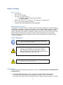
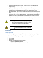
Punch Series Light
User Manual (IP20 Protection)
1
Table of Contents Before you Begin_________________________________________________ 3 What is Included_________________________________________________ 3 Unpacking Instructions_____________________________________________3 Symbol Definitions________________________________________________ 3 Safety Notes_____________________________________________________ 3 Introduction_____________________________________________________ 4 Product Description_______________________________________________ 4 Features________________________________________________________ 4 Quick Start______________________________________________________ 5 Rear Bulkhead Image______________________________________________6 A/C Power_______________________________________________________7 Control Selection_________________________________________________ 8 Operation_______________________________________________________8 UIM Operation___________________________________________________8 Functional Requirements___________________________________________9 Technical Specifications____________________________________________15 Limited Warranty_________________________________________________18 General Care, Maintenance & Contact Us______________________________19 2
Before You Begin What is Included •
•
•
•
•
•
User’s Manual
One (1) Punch Plus light
AC Power Input cable with plug
o USA voltage (120Vac), three-prong plug standard
o 1- 120/240V Adapter
o
o
o
Diffuser lens, three (3), 15 , 30 and 55 , 1 scrim bag and 1 doughnut frame
One (1) Yoke Pin with attaching hardware
External User Interface Module UIM ( Sold Separately)
Unpacking Instructions Immediately upon receipt of this light, carefully inspect the shipping packaging for any obvious signs of
damage from mishandling or exposure to the elements. If any is noted, please provide this information
to the shipper immediately so that the proper claims can be processed. Place packaging in upright
position (with labeling and markings in readable orientation) and open the top end of the carton. Verify
that all material shown above in the “What is included” section is present and in good condition.
Remove the light and associated material from the carton and place the light on a stable surface or
mounting configuration.
Symbol Definitions Note: This symbol indicates important information that should be
carefully considered and followed.
Note: This symbol indicates important safety information and
warnings. Special attention should be paid to reading,
understanding and heeding these warnings. Failure to
observe these warnings could result in damage to the fixture,
third-party equipment or harm to the user.
Note: This symbol indicates important information concerning the
operation or functions of this light.
Safety Notes The Punch Series light fixtures are for professional use only. Please Read Entire User Manual Before
Using Equipment.
•
•
•
This light is intended for indoor use only. The light is ETL & CE listed with IP20 protection.
Only qualified and certified personnel should perform installation, not for household use.
Punch Series light should always be installed/mounted in a stable and secure location or mounting.
3
Make sure that light is only used in dry location. Do not use light in or around falling water, wet
locations or moisture.
Always allow adequate ventilation of the light. Never cover or in any way obstruct the louvered
openings in the light.
If light is suspended either from above or below using yoke, make sure that a safety cable (not
supplied) is attached to the light and properly secured. The strength of the cable/chain should be
sized suitably to hold 6 times the weight the secured light. Note: Weight of fixture is 50 lbs.
When mounting the light, make sure that only hardware rated for the weight and size of the fixture is
used.
Never look directly into the light source while the fixture is turned on. Light source is very bright and
could cause damage to eyes.
Do not probe or touch any interior features of the fixture. This includes the LED sources inside the
barrel of the light. Doing so may cause damage to the fixture and/or may present a shock or burn
hazard.
Always make sure that the light fixture is connected to the proper power source with proper voltage
and current ratings. Also, make sure that adequate over current protection is provided for the circuit
as well.
•
•
•
•
•
•
•
Note: This light contains no user serviceable parts. Do not open
the light housing or attempt any repair or modification of the
light. Failure to observe this warning could result in damage
to the light, injury and/or voiding the limited warranty.
Warning! Inserting objects or fingers inside louvered openings
could result in a shock hazard/injury and damage to the
light.
Introduction Product Description The Punch series light is a professional grade, LED based, fixture which provides exceptional light
output and control. The light is capable of standalone, tethered remote, wired DMX, or wireless DMX
control and offers a full array of brightness settings as well as Strobe and Lightning functions.
Features •
•
•
Light Off Control
CIM/UIM Control
DMX control (Compatible with Slow and Fast speeds)
o Up to 500 selectable DMX addresses
o Daisy-chain operation of up to 32 lights in one string
o Controls Brightness, Fade, Strobe and Lightning modes
4
Setup Quick Start Remove the AAdyn light from its protective shipping packaging and place it in a safe and secure location for
setup or use.
Prior to proceeding further, make sure that light is resting on a stable surface or is
properly attached to a mounting location using the supplied yoke and yoke pin
mounting system.
Make note of the location of the inputs and outputs along with the light controls
found on the light’s rear bulkhead.
5
The 6’0” AC power cable for the Punch series light is located in a plastic bag under the diffuser kit.
•
Uncoil the black AC power cord from the holder and plug the blue female end into the AC Input
receptacle on the lower right portion of the housing.
6
Warning!
Lights operate on grounded 110Vac, 50/60Hz or 240Vac, 50/60Hz
AC Input. AC Supply Source must be sized properly and have
approved protection circuitry for safe operation. Take care to
observe all proper precautions when connecting power.
Warning!
Lights are intended for indoor operation and use only. Use in safe
and dry location only
•
•
Plug the male end of the AC power cord into an appropriate AC power source.
•
Turn on light by pressing the green power switch located in the upper right hand portion of the rear
bulkhead, as shown above.
•
Upon power up, the light will turn on immediately to its full brightness unless a specific “Power On”
Setting which has been previously programmed into the light. This “Power On” Setting will be
covered later in these instructions.
•
The Internal UIM (User Interface Module) is mounted on the bulkhead. The External UIM port is
located on the bottom of the bulkhead.
•
The display on the UIM will display the following Splash Screen message upon power up.
Aadyn Technology Remote Interface •
Using the Left/Right Arrow button, a desired brightness level can be selected. Other functions are
also available and can be viewed using the UIM by pressing the Up/Down arrow to the desired menu
function as detailed below in section 1.0, then pressing the (√) once a function has been selected.
All of these functions are covered later in these instructions.
•
The (X) button on the UIM is a non-latching douse switch which, when pressed, will momentarily
extinguish the light. Releasing the switch will allow the light to return to operation at its previous
setting.
AC Power Punch series lights operate on standard single phase AC power.
• Input voltage range: 100 – 277Vac
• Input frequency range: 50/60 Hz
7
Warning! Standard power cord supplied with Punch light is intended to
connect with standard, single-phase 110-120 Vac, 60 Hz USA circuit. Other
power cords for connection to other countries’ single phase circuits are
available as options. No other special adjustments or changes are required for
operation at international voltages.
Warning! Never connect Punch series lights to anything other than a singlephase circuit. Connection to three-phase power can/will cause serious damage
and/or bodily injury.
Control Selection The light can be controlled via three means of interface as shown below:
OFF
CIM/UIM
DMX (wired or wireless)
CIM/UIM Operation 8
1. Functional Requirements
The AAdyn Punch light is controlled by software (embedded firmware). In general the software shall control the
light and accept user inputs from multiple device types. Via the user inputs the light may be controlled and
various parameters may be saved in non-volatile memory.
The software shall monitor input from the following:
• CIM – an AAdyn proprietary Control Interface Module
• UIM – an AAdyn proprietary User Interface Module.
• DMX – a unidirectional digital network based on the DMX512 standard.
• Cancel (X) – which also referred to as the douse button, is a button that shuts off the light while it is
pressed.
The following sections provide all of the functional requirements for the AAdyn Punch Light Series.
1.1. Proprietary Control/User Interface Module Requirements
Note: Operation of the integral Control Interface Module (CIM) is identical to that of the User Interface
Module (UIM)
•
The CIM/UIM Remote Interface Controller has a backlit LCD display that the software shall control
and six user input keys. The keys shall provide the following functionality:
• UP/DOWN keys – select the parameter to be controlled.
• LEFT/RIGHT keys – adjust the value of the selected parameter.
• CHECKMARK (Enter) key – some parameters are only put into effect after the enter key is
pressed. It also causes savable values to be stored.
• Red ‘X’ (UIM remote douse) – shall cause the light to be extinguished while it is pressed.
•
The software shall display a menu of parameters on the UIM controller. The parameters listed below
shall be displayed in the order shown from top to bottom when the down key is pressed and shall
default to LIGHT CONTROL. When the up key is pressed the order will proceed from LIGHT
CONTROL to the bottom of the list, then upwards.
•
•
•
•
•
•
•
•
•
•
•
•
•
LIGHT CONTROL
UIM BRIGHTNESS
UIM FADE
UIM EFFECT SELECT
UIM EFFECT FREQUENCY
DMX BASE ADDRESS
DMX CHANNEL MODE
WIRELESS SHOW ID
MODEL NAME / SW VERSION / SN# / LIGHT UNIQUE ID / RADIO SW
RECALIBRATION HOURS / RESET FACTORY DEFAULT
POWER ON SETTING
SAVE CUSTOM
RECALL SETTING
Under each parameter, the software shall present settings pertaining to the parameter for the user to
select. The settings shall be:
• POWER ON SETTING
9
•
•
•
•
The software shall present individually sixteen startup profiles to the user: PRESET1,
PRESET2, PRESET3, CUSTOM1 through CUSTOM12, and OFF changing the choice
each time the right or left arrow button is pressed.
When a profile is selected by the user, the software shall save this choice to non-volatile
memory.
When power is applied to light the software shall determine which stored parameters will
be recalled and put into effect. If a startup profile has be previously set it will be used to
set the parameters.
If the POWER ON SETTING is set to OFF the software will restore the parameters that
were automatically saved the last time the light was in operation. The parameter recalled
are:
• LIGHT CONTROL
• UIM BRIGHTNESS
• UIM FADE
• UIM EFFECT SELECTION
• UIM EFFECT FREQUENCY
• DMX BASE ADDRESS
• DMX CHANNEL MODE
•
LIGHT CONTROL
• This parameter shall support four values: “UIM”, “Wired DMX”, “Wireless DMX” and
“OFF”.
• Selecting “UIM” shall allow the UIM button pad to control all functions of the light.
Selecting “DMX” shall allow the DMX controller to control all functions of the light.
Selecting “OFF” shall turn off the light The light shall turn on and the prior brightness
level shall be restored when “UIM” is selected again.
• The factory default for LIGHT CONTROL is UIM (CIM/UIM control).
• Note: In this mode, control is through either and/or both the integral CIM or
optional UIM.
•
UIM BRIGHTNESS parameter:
• Values from 0 to 100 percent that can be incremented or decremented in steps of 0.3,
0.7 and 1.0 on slow scroll. Medium and medium fast shall scroll by one and fast shall
scroll by five.
• Each setting value shall represent a brightness level where 0 percent is off and 100
percent is the maximum brightness of the light.
• The change from one brightness value setting to another positive value shall be as
smooth as possible. The built in smoothing delay shall be 250ms. If the DMX controlled
brightness level is changed from a positive value to 0, the software shall turn the light off
within one half second unless UIM FADE is non-zero.
• The factory default for the UIM BRIGHTNESS parameter shall be 100%.
•
DMX BASE ADDRESS
• This parameter shall range between 1 and 508 for 5 CHANNELS mode.
• This parameter shall range between 1 and 511 for 2 CHANNELS mode.
• This parameter shall range between 1 and 512 for 1 CHANNEL mode.
• It shall represent the DMX address on the network that is used to address the light.
• This parameter shall be meaningful only if the light control is set to “DMX”.
• The factory default for DMX BASE ADDRESS is 1.
•
DMX CHANNEL MODE
• There shall be three modes of operation when the light is under DMX control. These
modes are called: 1 CHANNEL, 2 CHANNELS, and 5 CHANNELS mode. Each mode is
described in section 3.3 below.
• The factory default for the DMX CHANNEL MODE shall be 5 CHANNELS mode.
10
•
RECALL SETTING
• The software shall present individually fifteen choices to the user: PRESET1, PRESET2,
PRESET3, and CUSTOM1 through CUSTOM12 changing the choice each time a right
or left arrow button is pressed. The CUSTOM settings are described below.
• The PRESET settings shall be hard coded into the software and not changeable by the
user. Preset values are described below.
• When the user presses the select (green check) button, the software shall set these
parameters with the saved settings from a CUSTOM or a PRESET, given the profile the
user has chosen:
o LIGHT CONTROL
o UIM BRIGHTNESS
o UIM FADE
o UIM EFFECT SELECTION
o UIM EFFECT FREQUENCY
o DMX BASE ADDRESS
o DMX CHANNEL MODE
•
•
The factory default for the RECALL SETTING parameter shall be PRESET1.
SAVE CUSTOM
• The software shall present individually twelve choices to the user: CUSTOM1 through
CUSTOM12 changing the choice each time the right or left arrow button is pressed.
• When the custom setting is selected (green check button) by the user, the software shall
save these parameters to non-volatile memory:
• LIGHT CONTROL
• UIM BRIGHTNESS
• UIM FADE
• UIM EFFECT SELECTION
• UIM EFFECT FREQUENCY
• DMX BASE ADDRESS
• DMX CHANNEL MODE
•
The factory default for the SAVE CUSTOM parameter shall be CUSTOM1.
•
MODEL NAME
• Current model names:
! Punch Plus
! Tungsten
•
SOFTWARE VERSION
• The software shall maintain and display the software version.
•
RECALIBRATION PT
• The software shall start at 25000 hours and count down to zero and then count
negatively if necessary to let the user know it is time to have the LED’s replaced. The
time shall count down based on hours of continuous use at a particular brightness
setting.
•
UIM FADE parameter:
• Values from 0 to 100 percent that can be incremented or decremented in steps of 0.3,
0.7 and 1.0 on slow scroll. Medium and medium fast shall scroll by one and fast shall
scroll by five.
• Each setting value shall represent a delay in the increase or decrease of the UIM
BRIGHTNESS parameter.
11
•
•
•
•
•
UIM EFFECT SELECT
• The software shall present individually thirteen choices for the UIM EFFECT SELECT
parameter:
• NONE (OFF) – Turn off any current effect
• STROBE,
• LIGHTNING1 SGL,
• LIGHTNING1 RPT,
• LIGHTNING2 SGL,
• LIGHTNING2 RPT,
• LIGHTNING3 SGL,
• LIGHTNING3 RPT,
• LIGHTNING4 SGL,
• LIGHTNING4 RPT,
• LIGHTNING5 SGL,
• LIGHTNING5 RPT,
• LIGHTNING CYCL
• The choice shall change by one each time a right or left arrow button is pressed.
•
•
•
•
•
•
•
•
0 shall indicate that the UIM BRIGHTNESS parameter change is to occur immediately
and 100 percent shall introduce a three second delay in changing the current parameter
value to the requested value.
At power on, the value of UIM FADE shall default to 0 percent if there is no power on
profile.
The factory default for the UIM FADE parameter shall be 0%.
The UIM FADE parameter is only active when UIM EFFECT is set to NONE (OFF).
STROBE shall make the LEDs emit pulses of light at a 30 percent on / 70 percent off
duty cycle and that are of a user designated frequency and brightness. These
parameters are UIM EFFECT FREQUENCY and UIM BRIGHTNESS.
LIGHTNINGx SGL shall make the LEDs emit pulses of varied length and brightness
based on internal parameters to simulate a lightning strike. SGL indicates that this
sequence shall be shown only once each time the Enter Key is pressed. The length and
brightness components of lightning shall be defined in the software. There shall be five
different sequences of lightning defined and designated by a number where the x is
located.
LIGHTNINGx RPT shall make the LEDs emit pulses of varied length and brightness
based on internal parameters to simulate a lightning strike. RPT indicates that this
sequence shall be shown repeatedly, with each sequence separated by a two second
off interval. The length and brightness components of lightning shall be defined in the
software. The same five single sequences defined above shall be used for the repeat
lightning.
LIGHTNING CYCL shall show each sequence in order with each sequence separated
by a two second off interval. At the end of the fifth sequence, the process shall be
repeated.
If a LIGHTNING effect has been started, it shall be completed even if the user disables
effects during the sequence.
At power on, the UIM EFFECT SELECT shall default to NONE(OFF) if there is no power
on profile.
The factory default for the UIM EFFECT SELECT shall be NONE.
UIM EFFECT FREQUENCY
• Values from 0 to 100 percent that can be incremented or decremented in steps of 0.3,
0.7 and 1.0 on slow scroll. Medium and medium fast shall scroll by one and fast shall
scroll by five.
• Each setting value shall represent how quickly the lightning and strobe effects operate.
Higher numbers represent a slower effect.
12
•
•
The factory default for the UIM EFFECT FREQUENCY parameter shall be 75%.
The preset values shall be set as follows:
• PRESET 1
! LIGHT CONTROL
! UIM BRIGHTNESS
! UIM FADE
! UIM EFFECT SELECTION
! UIM EFFECT FREQUENCY
! DMX BASE ADDRESS
! DMX CHANNEL MODE
•
•
PRESET 2
! LIGHT CONTROL
! UIM BRIGHTNESS
! UIM FADE
! UIM EFFECT SELECTION
! UIM EFFECT FREQUENCY
! DMX BASE ADDRESS
! DMX CHANNEL MODE
PRESET 3
! LIGHT CONTROL
! UIM BRIGHTNESS
! UIM FADE
! UIM EFFECT SELECTION
! UIM EFFECT FREQUENCY
! DMX BASE ADDRESS
! DMX CHANNEL MODE
=
=
=
=
=
=
=
UIM
100%
0%
NONE
0%
1
5
=
=
=
=
=
=
=
UIM
45%
0%
NONE
0%
1
5
=
=
=
=
=
=
=
UIM
25%
0%
NONE
0%
1
5
•
The custom profile shall default to these settings:
o LIGHT CONTROL
=
UIM
o UIM BRIGHTNESS
=
100%
o UIM FADE
=
0
o UIM EFFECT SELECTION
=
NONE
o UIM EFFECT FREQUENCY
=
75%
o DMX BASE ADDRESS
=
1
o DMX CHANNEL MODE
=
5
•
The software shall implement medium, medium fast and fast scroll where noted. If the Right or Left
Arrow button is held down for one half second, the values shall be medium scrolled on the display. If the
Arrow button is held down for two seconds the values shall be medium fast scrolled on the display. If the
Arrow button is held down for six seconds the values shall be fast scrolled by five on the display.
•
The software shall power the LED’s based on UIM settings and any saved profile described under
POWER ON SETTING before detecting the presence of a UIM (User Interface Module).
•
If a UIM cannot be detected at light startup, the software shall transmit the AADYN TECHNOLOGY
splash screen and check again next time through the main loop. If a UIM is attached after startup, the
software shall display the UIM BRIGHTNESS screen.
•
If the UIM is removed after startup, the software shall maintain the current settings. If the UIM is
reattached later, the splash screen shall show again and any value in the buffer shall be processed.
13
The software shall retain the menu state after the UIM is unplugged and remain on the same screen if
the UIM is reattached.
1.2. Douse Switch/Douse Button
•
The software shall separately detect and process a press and release of the red Cancel (X) button
from the UIM. On Cancel button press, the software shall turn off the LED’s immediately. On
Cancel button release, the software shall turn on the LED’s immediately if the Douse switch is not
being pressed.
1.3. Wireless DMX Operation- Special User Instructions Enclosed
•
•
•
The wireless transmitter/receiver of the Punch light is designed to communicate with City Theatrical
transmitters/ receivers.
The back panel of the Punch light has three LED indicator lights (red, yellow, green) that show
wireless signal strength/link.
When installing the Punch light, make sure to adjust wireless antenna for best signal reception.
1.4. DMX Controller Interface Requirements
•
•
The software shall accept input from the DMX512 controller that represents user requested values
for BRIGHTNESS, FADE, EFFECT, EFFECT FREQUENCY and EFFECT ACTIVATION.
The DMX input to the light is mapped as follows for each DMX MODE:
• 1 CHANNEL mode: Each DMX channel shall be used for BRIGHTNESS control.
• 2 CHANNELS mode: DMX channel 1 shall be used for BRIGHTNESS control. DMX
channel 2 shall be used for FADE control.
• 5 CHANNELS mode: DMX channel 1 shall be used for BRIGHTNESS control. DMX
channel 2 shall be used for FADE control. DMX channel 3 shall be used for EFFECT
SELECTION control. DMX channel 4 shall be used for EFFECT FREQUENCY control.
DMX channel 5 shall be used for EFFECT ACTIVATION control.
• When the mode is set for more than one channel, BRIGHTNESS will be at the DMX BASE
ADDRESS, FADE will be at DMX BASE ADDRESS + 1, etc.
• DMX BRIGHTNESS parameter shall range between 0 and 255. 0 means the light is off and
255 means the light is 100% bright.
• DMX FADE parameter shall range between 0 and 255. 0 means that fade is completely off
and 255 means that a three to four second fade is present.
• DMX EFFECT SELECTION parameter shall range between 0 and 255. The selections shall
be as follows:
0:
No Effect Selected
1 – 40:
Lightning 1 Selected
41 – 80: Lightning 2 Selected
81 – 120: Lightning 3 Selected
121 – 160: Lightning 4 Selected
161 – 200: Lightning 5 Selected
201 – 255: Strobe Selected
• DMX EFFECT FREQUENCY parameter shall range between 0 and 255. 0 means that the
effect frequency is at a maximum. 255 means that the effect frequency is at the minimum.
• DMX EFFECT ACTIVATION parameter shall range between 0 and 255. 0 means that he
effect is off. 1 through 255 means that the effect is activated. An effect shall be reactivated
only if channel 5 is brought to 0 and then made positive again.
14
GENERAL SPECIFICATIONS:
15
PUNCH PLUS
16
PUNCH TUNGSTEN
17
Limited Warranty AADYN TECHNOLOGY, LLC
LIMITED WARRANTY
AAdyn Technology, LLC (“AAdynTech”) products are covered by a limited warranty against
manufacturing defects for two (2) years from the date of purchase by the original purchaser.
AAdynTech’s liability is limited, at AadynTech’s option, to repair or replacement of the product with
the same or an equivalent product and does not include installation costs, removal costs, or
transportation costs. AAdynTech reserves the right to determine whether the AAdynTech product is
defective. Damage due to normal wear and tear, incorrect installation, misuse, abuse, accident, or any
cause other than a manufacturing defect is not covered by the warranty. AAdynTech disclaims any
liability for damage to products, adapters, other property, or personal injury resulting in whole or in
part, from improper installation or use of its products. Components not manufactured by AAdynTech
are subject to the warranty or guarantee set forth by the manufacturer thereof, and then only to the
extent AAdynTech is able to enforce the warranty or guarantee.
In order to make a warranty claim, you must notify AAdynTech in writing within sixty (60)
days after your discovery of the defect, obtain from AAdynTech an RMA, then provide proof of
purchase, such as the invoice, and promptly return the product to AAdynTech or its authorized service
provider, freight prepaid.
THE FOREGOING WARRANTY PROVISIONS ARE EXCLUSIVE AND ARE GIVEN
AND ACCEPTED IN LIEU OF ANY AND ALL OTHER WARRANTIES, WHETHER EXPRESS
OR IMPLIED, INCLUDING WITHOUT LIMITATION ANY WARRANTY AGAINST
INFRINGEMENT AND ANY IMPLIED WARRANTIES OF MERCHANTABILITY OR FITNESS
FOR A PARTICULAR PURPOSE.
IN NO EVENT SHALL AADYNTECH BE LIABLE FOR INCIDENTAL,
COMPENSATORY, CONSEQUENTIAL, DIRECT, SPECIAL OR OTHER DAMAGES.
AADYNTECH’S AGGREGATE LIABILITY WITH RESPECT TO A DEFECTIVE PRODUCT
SHALL IN ANY EVENT BE LIMITED TO THE REPAIR OR REPLACEMENT OF THAT
DEFECTIVE PRODUCT OR, AT AADYNTECH’S OPTION, THE REIMBURSEMENT OF THE
PURCHASE PRICE THEREFOR.
This warranty is effective for purchases of AAdynTech’s product on or after the effective date
set forth below. AAdynTech reserves the right to modify this warranty from time to time. Any
modification of this warranty shall be effective for all orders placed with AAdynTech on or after the
effective date of such revised warranty.
Effective Date: November 11, 2014
All prices and specifications are subject to change without notice.
18
General Maintenance and Care This light is intended for indoor use only. When not in use, the light should be stored in a generally dry
and dust free area. General maintenance and care consists of making sure that the light always has
good ventilation and that nothing is obstructing free air flow through and around the light. Do not use
chemicals to clean light. Any cleaning of the light, especially the LED optics should be with a damp, not
wet, soft cloth that is non-abrasive.
Contact Us AAdyn Technology, LLC
80 Route 4 East, Suite 120
Paramus, NJ 07652
201-368-2800
www.aadyntech.com
19