1
AVBIS 3000 Operation Manual
(3000M, 3000C, 3000P)
VERSION 9 AND HIGHER
AVID Corporation
222 International Drive / Suite 105
Portsmouth, NH 03801
Copyright © 2010
1
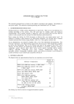
Table of Contents
3 - Neck Finish Diagram
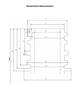
51 - Bottle Measurements Guide
4 - Quick Reference – Program Setup
79 - Calibration Guide
5 - Quick Reference – Motion Setup
87 - Common Error Messages
7 - Control Screen
89 - Troubleshooting
8 - System Controls
95 - Software Conflicts
9 - Part Buttons
10 - Stage Controls
11 - Data Setup: Data DisplayTab
96 - Returning Equipment for Repair or
Replacement
Appendix A – In-Depth Bottle Programming
Guide
12 - Data Setup: Data Setup Tab
Appendix B – Bottle Wall Thickness Module
13 - Data Setup: Measurement Setup Tab
15 - S Types
23 - Data Setup: Allowed Data Types Tab
24 - Data Setup: Excel Setup Tab
25 - CAD Setup
27 - Basic Setup: Wall Tab
28 - Basic Setup: Bore Gauge Tab
31 - Basic Setup: Measure Tab
32 - Basic Setup: Camera Tab
33 - Basic Setup: System Tab
34 - Basic Setup: Autofeed Tab
35 - Basic Setup: Conveyor Tab
36 - Basic Setup: Misc Tab
37 – Basic Setup: Concentricity Tab
43 - Basic Setup: Advanced Options
47 - Feeder Controls
49 - Using Bladder Restrictor Collar
50 - Dimensional Measurement Requisites
2
Neck Finish Dimensions
Quick Reference
Programming a New Bottle/Preform For Measurement
PROGRAMMING SHOULD ONLY BE CONDUCTED BY A SYSTEM PROGRAMMER
1)
Press the NEW BOTTLE button. Press the CREATE button. Save the new bottle profile as a new file with a name that will
identify the bottle.
2)
Assign your new profile to a Part Button. The assigned button will highlight green.
3)
Place the bottle (or preform in a fixture) at the center of the rotary stage.
4)
Press the DATA SETUP button.
5)
Using the red arrow buttons at the bottom of the screen, scroll to or click on the ALLOWED DATA TYPES tab.
6)
Enable those dimensions to be measured. If multiple measurements of the same dimension are needed (e.g. width
dimensions at different heights, or H at different shoulder locations), press the green up arrow button to enable extra
measurements. Note that certain dimensions require that another dimension is enabled and being measured (see
Requisites section of the manual). SAVE your selections to the created bottle file.
7)
Using the red arrow buttons at the bottom of the screen, scroll to the DATA SETUP tab.
8)
Enter Nominal and Tolerance values for each dimension by pressing on the individual cell you wish to change and enter the
new value on the pop-up keypad (values for “Left” dimensions will automatically be copied to the “Right” of that dimension).
If you need to enter a Y Position (for example, ID depth or width heights), enter a Y Position value accordingly.
9)
Turn the dimensions ON or OFF at the angles you do or do not wish the AVBIS to measure at. If you wish to add or change
an angle to measure at, press the cell in the Angle column and enter in the angle on the pop-up keypad. Note, HghtLEFT
and HghtRight MUST be ON on ALL rows in which any other cell is turned ON. (Example, if F is ON at angle 65, HghtLeft
and HghtRight must be ON at angle 65). Also note that if you wish to use the thread start search, T and E must be enabled
at zero (0) (see Requisites section of the manual). Also, ensure that a zero (0) angle is setup in the first row, as this will be
the first set of measurements.
10) Using the red arrow buttons at the bottom of the screen, scroll to the MEASUREMENT SETUP tab. Enable necessary
searches, fields, offsets and S Type by pressing the corresponding on/off cells or entering the value. If the bottle is a wide
mouth (ID is greater than 2”) variety, 2 measurement fields will be necessary. SAVE your selections. Press HIDE. (see the
Measurement Setup section for further information.)
11) Press the CAD SETUP button in the System Controls menu. Press the first dimension along the top of the screen to check
limits and field for correct positioning and measurement. Adjust limits and fields if necessary (see CAD SETUP section for
further definitions). When you are satisfied with setup, press HIDE. SAVE your changes when prompted. (if no changes
were made in CAD Setup, the AVBIS will not prompt to SAVE.)
12) With the bottle on the rotary stage, press RUN. Observe the crosshairs on the video display as measurements are made.
When complete, make any necessary changes in CAD Setup or Data Setup. SAVE any changes. The Bottle Profile is now
complete.
- Note: For bottles with similar characteristics (e.g. bottles with the same neck finish dimensions, but different heights), program
one bottle completely as instructed above. For the next bottle, press NEW BOTTLE in System Control, but press MODIFY when
prompted. The system will then ask if you wish to use an existing profile as a template. Select the existing profile and OPEN.
The system will then prompt you to Save As another filename. The new file will contain the same setup (including loading,
unloading and data export links). Change the appropriate values in DATA SETUP / CAD SETUP.
- Obviously, different bottles will have different setups. An HDPE snap-cap “pill” bottle will have a different method of
measurement than a PET salad dressing bottle. The same AVBIS is capable of measuring both bottles, however, there is no
“golden standard” of how to program them. Practice and experimentation as well as some trial and error will yield bottle
programs that measure the desired dimensions in the desired locations, regardless of operator.
- This reference guide is NOT a substitute for formal training at AVID and coverage by the AVID support contract.
4
Programming A New Bottle for Conveyor Loading and Unloading (AVBIS 3000C)
PROGRAMMING SHOULD ONLY BE CONDUCTED BY A SYSTEM PROGRAMMER
1)
Follow instructions for Programming a New Bottle for Measurement.
2)
Ensuring that the bottle part button desired is highlighted, press the BASIC SETUP button in the System Controls menu. Place the
matching bottle on the conveyor, close to -- but not at --the load position. Press the CONVEYOR tab.
3)
Press the NEXT BOTTLE button. The rotary stage will lower so the laser reflector is in the correct position. The conveyor will move the
bottle until it cuts the laser beam. In the Stages menu, press the INPUT CONVEYOR button and advance the bottle using the on-screen
arrow buttons until the bottle is positioned correctly in front of the loading “jaw.” Press the SET button under the Next Bottle button. Press
YES to associate this setting to the bottle file.
4)
Press the Load Pos GO button. The load arm will move the bottle to a default position on the rotary stage. If the bottle moves too quickly or
too slowly, increase or decrease the LOAD SPEED setting. In the Stages menu, press the LOAD ARM button and move the bottle until it is
centered on the rotary stage. You will have to hold the bottle against the arm when moving the arm backwards. Once centered, press the
Load Pos SET button. Press YES to associate this setting to the bottle file.
5)
Press the Unload Pos GO button. The rotary stage will move to the exit position and the load arm will push the bottle from the rotary stage
onto the weight scale. In the Stages menu, press the LOAD ARM button and move the bottle until it is positioned on the weight scale. Press
the Unload Pos SET button. Press YES to associate this setting to the bottle file.
6)
Press the Eject Pos GO button.
7)
a.
Load Arm Only System - The load arm will push the bottle from the weight scale off the system. In the Stages menu, press
the Load Arm button and move the bottle until it is off the weight scale. Press the Eject Pos SET button. Press YES to
associate this setting to the bottle file. Press SAVE. Save the changes to the appropriate bottle file. Press HIDE.
b.
System With Eject Arm – The eject arm will slide out and push the bottle off the weight scale onto the output conveyor, or
receptacle. In the Stages menu, press the Eject Arm button and move the bottle until it is off the weight scale. Press the
Eject Pos SET button. Press YES to associate this setting to the bottle file. Also enter in an Eject Distance for the output
conveyor (if equipped) to move after the bottle has been placed there. Press SAVE. Save the changes to the appropriate
bottle file. Press HIDE.
Place several bottles on the input conveyor. Press the FEEDER button in the System Controls menu. Select the number of bottles on the
input conveyor by left clicking pressing the appropriate number, THEN right clicking the appropriate number. Press the CLEAR DATA
button. Press YES when prompted. Press RUN. Observe the loading and unloading procedures. When complete, make any necessary
changes in the Basic Setup / Conveyor tab. SAVE any changes.
5
Programming A Preform or Bottle for Pickup Arm Loading and Unloading (AVBIS 3000P)
PROGRAMMING SHOULD ONLY BE CONDUCTED BY A SYSTEM PROGRAMMER
1)
Follow instructions for Programming a New Bottle for Measurement.
2)
Load the preform template into the tray and load the preforms into the grid slots, starting with slot 1. If measuring bottles, load the bottle
centering grid into the tray and load the bottles into the grid, starting in the top left slot.
a.
In order to program correctly, a preform MUST be placed in the top left slot. This is the “first on tray” position, regardless of
number written on the slot.
3)
Ensuring that the correct bottle part button desired is highlighted, press the BASIC SETUP button in the System Controls menu. Press the
AUTOFEEDER tab.
4)
Lining up with the Rotary Stage - Press the 1st ON TRAY button. In the Stage Control menu, press the BOTTLE TRAY button. Advance the
tray until the first preform/bottle is in-line with the center of the rotary table. Press the TRANSPORT ARM button. Move the Transport Arm
until the pickup tool is directly over the preform / bottle. Press the PICKUP ARM button. Lower the pickup arm until the pickup tool is just
inside / just over the first preform/bottle on the tray. Adjust the tray position or transport arm if necessary by retracting the pickup arm
slightly and moving the tray or transport arm. When the first preform / bottle is lined up, press the SET button.
5)
Setting the Pick Up Height – Press the PICK HEIGHT button. Press the PICKUP ARM button in the Stage Control menu. Lower the Pickup
Arm the tool is to an appropriate depth in the preform/bottle. Press the SET button.
6)
Setting the Lift/Transport Height - Press OPEN GRIPPER button. Adjust the air pressure, if necessary, by clicking on the air “pressure”
display and raising or lowering the pressure. Press the LIFT HEIGHT button. Press the PICKUP ARM button in the Stage Control menu.
Raise the pickup arm until the bottom of the preform/bottle is higher than the rotary stage or fixture on the rotary stage, and above the other
preforms/bottles in the tray. Press the SET button. If in doubt, raise the pickup to its highest point and click set.
7)
Setting the Rotary Center – Press the ROTARY CENTER button. Press the TRANSPORT ARM button in the System Control menu. Move
the transport arm until the preform/bottle is centered over the rotary table/preform holder/bottle fixture. Press the Pickup Arm button. Lower
the preform/bottle until it is in the holder/fixture or until the bottle rests on the center of the rotary table. (if the preform/bottle was not
centered correctly, raise the arm slightly, press the TRANSPORT ARM button, and center the preform/bottle over the holder/fixture/rotary
stage center. Press the SET button.
8)
Setting the Drop Height – Press the DROP HEIGHT button. Press the PICKUP ARM button. Lower the preform/bottle until it is just seated
in the holder/fixture or until the bottle is placed on the rotary stage. Press the SET button.
9) If your system is equipped with a weight scale or concentricity option, follow the above steps to set appropriate positions for each.
10) Setting Grid Spacing – Calculate or measure the center to center distance between preforms/bottles in the tray. Enter the horizontal
distance between preforms/bottles in X and the vertical distance in Y. (Systems with enclosures do not have this option.)
11) Testing – Press the STEP THROUGH button. The system will now walk through all the loading and unloading positions of the autofeeder.
At each point, the system will query the operator to OK the position. If the position is incorrect, and the operator presses the NO button, the
system will stop the walk through at that position so the operator may correct the location. When complete, press SAVE.
6
Standard Operating Procedures (SOP)
AVBIS 3000 Manual Vision Measurement System
1) Click the part button associated with the bottle or part you will be measuring. This will load the program.
2) The system may query you to load parts or fixtures a certain way onto the rotary stage, and/or verify that the correct bottle or
part is has been selected/loaded, and/or load a particular fixture onto the system. Confirm that you have read and will follow the
instructions by clicking on the OK button.
FAILURE TO FOLLOW THE INSTRUCTIONS MAY RESULT IN IMPROPER MEASUREMENT OF PARTS OR DAMAGE TO
THE SYSTEM!
3) Press the Run With Feeder button.
7
Enter the number of total parts you will be measuring. Enter the pause time (in seconds) for the system to wait between the
switching of parts (generally 4-10 seconds). Place the first part on the rotary table. Click the Run button. The part will be run.
When the part is finished, the system will prompt the operator to remove the part. Remove the part. The system will now prompt
the operator to place a new part onto the rotary stage. When a new bottle is detected, the timer (pause time) will begin. Once it
reaches 0, the system will begin measuring the next part.
Faults
STOP BUTTON (Non-emergency situations)
If for any reason the STOP button is clicked while the system is running, the system will produce a fault and stop moving at the
next available “halt” position. Check that nothing is jammed and click RESET. Stages will reset and home. After homing, Hide
from the Feeder window, select the proper bottle file, and continue as normal.
EMERGENCY STOP SWITCH (Emergency situations ONLY)
In the event of an emergency, press in the EMERGENCY STOP switch on front of the machine. This will immediately cut all
power to the stages and motion devices. When you have cleared out the problem, pull the emergency stop out and press the
Blue RUN button on the front of the computer box (if applicable). Click on the Reset button and allow the stages to reset and
home. Return to regular routine.
8
Standard Operating Procedures (SOP)
AVBIS 3000 Conveyor Vision Measurement System
1) Click the part button associated with the bottle or part you will be measuring. This will load the program.
2) The system may query you to load parts a certain way onto the conveyor, and/or verify that the correct bottle or part is has
been selected/loaded, and/or load a particular fixture onto the system. Confirm that you have read and will follow the instructions
by clicking on the OK button.
FAILURE TO FOLLOW THE INSTRUCTIONS MAY RESULT IN IMPROPER MEASUREMENT OF PARTS OR DAMAGE TO
THE SYSTEM!
3) FOR PREFORMS – If measuring preforms, the system CANNOT be run using the Feeder! Each preform must be loaded and
unloaded by hand into a fixture on the rotary stage. Be sure to setup the fixture properly before running the preform.
FOR BOTTLES – Load the bottles in order of cavity number from left to right onto the conveyor. Make sure that the first bottle
(left most) is not blocking the laser beam.
9
4) PREFORMS – Load the first preform into the fixture on the rotary stage. Press the Test 1 Rotary button.
The preform will be run automatically. At the end of the measurement routine, the system will return to the main screen. If the
measurements all passed specifications set in the AVBIS, DATA PASSED will be displayed. DATA FAILED will be displayed if
any measurements were out of tolerance. Press the SEND DATA button to send the measured data to Excel. Repeat step 4a
until all preforms are measured.
BOTTLES – Press the Run with Feeder button. This will open the Feeder window.
Count the total number of bottles loaded onto the conveyor and enter this number in the Number of Bottles box by touching the
box and entering the total number on the pop-up keyboard and pressing the Enter button on the keypad.
A number of yellow balls will appear in the feeder window equal to the number of bottles you selected.
10
Press the RUN button in the feeder window. The system will home all stages before commencing measurement.
After homing the system will measure the bottles. After measurement, each bottle will be weighed and then ejected off the
system. Data from each bottle will be automatically sent to the Excel file after it is ejected from the system. Bottles that are within
programmed tolerances will be marked with a green ball. Bottles outside of programmed tolerances will be marked with a red
ball.
When the system has finished measuring and the STOP button switches to RUN, press the Hide button in the feeder window to
return to the main screen.
13) If sending data to Excel, open the Excel Worksheet in the Windows Taskbar (bottom of screen). Click on File Save As….
Save the file to the appropriate network location with an appropriate file name. Close Excel by clicking File Exit.
Faults
STOP BUTTON (Non-emergency situations)
If for any reason the STOP button is clicked while the system is running, the system will produce a fault and stop moving at the
next available “halt” position. Check that nothing is jammed and click RESET. Stages will reset and home. After homing, Hide
from the Feeder window, select the proper bottle file, and continue as normal.
11
EMERGENCY STOP SWITCH (Emergency situations ONLY)
In the event of an emergency, press in the EMERGENCY STOP switch on front of the machine. This will immediately cut all
power to the stages and motion devices. When you have cleared out the problem, pull the emergency stop out and press the
Blue RUN button on the front of the computer box (if applicable). Click on the Reset button and allow the stages to reset and
home. Return to regular routine.
12
Standard Operating Procedures (SOP)
AVBIS 3000 Picker Vision Measurement System
1) Click the part button associated with the bottle or part you will be measuring. This will load the program.
2) The system may query you to load parts a certain way onto the system, and/or verify that the correct bottle or part is has been
selected/loaded, and/or load a particular fixture onto the system. Confirm that you have read and will follow the instructions by
clicking on the OK button.
FAILURE TO FOLLOW THE INSTRUCTIONS MAY RESULT IN IMPROPER MEASUREMENT OF PARTS OR DAMAGE TO
THE SYSTEM!
3) Run with Feeder button. This will open the Feeder window.
Count the total number of parts loaded onto the tray and enter this number onto the display grid by first left-clicking on the grid,
then right-clicking on the total number. Individual tray cells can be turned off individually by right-clicking on them.
13
Press the RUN button in the feeder window. The system will home all stages before commencing measurement.
After homing the system will measure the parts. Data from each part will be automatically sent to the Excel file after it is ejected
from the system. Parts that are within programmed tolerances will be marked with a green square. Parts outside of programmed
tolerances will be marked with a red square.
When the system has finished measuring and the STOP button switches to RUN, press the Hide button in the feeder window to
return to the main screen.
13) If sending data to Excel, open the Excel Worksheet in the Windows Taskbar (bottom of screen). Click on File Save As….
Save the file to the appropriate network location with an appropriate file name. Close Excel by clicking File Exit.
Faults
STOP BUTTON (Non-emergency situations)
If for any reason the STOP button is clicked while the system is running, the system will produce a fault and stop moving at the
next available “halt” position. Check that nothing is jammed and click RESET. Stages will reset and home. After homing, Hide
from the Feeder window, select the proper bottle file, and continue as normal.
14
EMERGENCY STOP SWITCH (Emergency situations ONLY)
In the event of an emergency, press in the EMERGENCY STOP switch on front of the machine. This will immediately cut all
power to the stages and motion devices. When you have cleared out the problem, pull the emergency stop out and press the
Blue RUN button on the front of the computer box (if applicable). Click on the Reset button and allow the stages to reset and
home. Return to regular routine.
15
Control Screen
The control screen displayed at system start up is divided into three regions.
System Controls (top right)
- Permits access to setup and data screens and controls for frequently used functions.
Video Image (top left)
- The image display shows both live and stored images of the bottle as well as graphic displays of points measured
on the bottle.
Part Buttons (bottom)
- The Part Buttons section allows quick selection of commonly measured bottles, and displays the bottle file
currently active.
16
System Controls
(Note: Version 8 software has removed the Saved
Bottle and Reset buttons)
New Part #
The new part button is used when a new bottle or preform is
to be programmed. By pressing this button, the operator can
either create an entirely new bottle or preform profile, modify
a pre-existing bottle or perform template and save the new
values into a new bottle or preform profile, or call up a saved
bottle or preform profile for use.
Data Setup
Displays the menus for dimension selection, dimension
nominal and tolerance entry, measurement setup. Excel
setup and Feeder Setup.
CAD Setup
Displays an interactive menu and video screen, which permits
the operator to view and adjust measurement points and
dimensions selected in Data Setup.
Manual
Displays this manual in Microsoft Wordviewer®.
Basic Setup
Displays a new menu (at bottom of screen) with controls to
system hardware.
Stages
Pressing the Stages button will bring up a stage control
window, allowing control of each individual motion device.
Pressing this button also allows the operator to return all or
selected motion devices to their individual home limit
switches, move a single axis or place a device at its start
position.
Reset
Re-links and homes all stages.
Thickness / Concentricity (if equipped)
Switches screen to the wall thickness (no longer available as an option to the AVBIS 3000) or concentricity program (if equipped).
Send Data
The send data button is automatically activated after a bottle is measured. Data from the current bottle is stored in the measurement file and
may be viewed with the ‘View Data’ button, but is not stored to permanent data files until the ‘Send Data’ button is pressed. This permits the
operator to re-measure a bottle if required prior to saving the data. After sending data bottle data may be updated by changing the bottle count
and re-measuring the appropriate bottle. (Data cells in the Excel file will be overwritten with the new data. Other data storage files will be
appended with the bottle number and new data.)
Clear Data
The clear data button will reset the bottle count to ‘0’ and clear the stored data file that is used by external data analysis software such as ‘Excel
®’ or other statistical program.
View Data
Allows data gathered from last bottle or selected bottle (in Picker Feeder) to be viewed.
Exit to Windows
Exit will move the stages to home, close the program properly and then shut down the bottle program. To completely turn off power, shut down
the Windows operating system. Press the power button on the uninterrupted power supply (UPS) after the system shuts down.
Run Feeder
Displays the auto”picker”/conveyor control menu and associated feeder command buttons.
Bottle #
Current number of bottles that have been measured.
Test 1
The Test 1 button will execute the measurement program for the bottle highlighted in the part buttons area. Note, the bottle MUST be present on
the rotary stage before pressing this button. If the system is enclosed, the system will check if a door has been opened and reset and home the
stages if necessary.
17
Part Buttons
The Part Buttons area of the Control Screen permits the selection of different bottle inspection routines with the press of a single
button. This simplifies system operation when it is used by plant operators who might be unfamiliar with system setup. When a
button is selected it will turn green and the associated bottle part template file and setup parameters (including conveyor or
autofeeder setups) will be automatically loaded. The Y stage will also move to accommodate the bottle (puts the neck finish of
the bottle in view of the camera).
To clear a button of its’ assigned bottle profile, right-click on it and erase the part number. To overwrite a button, assign a new
bottle profile to the desired button. Overwriting the button does not overwrite the bottle profile it is linked to. Therefore, it is
possible to have many more bottle profiles than buttons.
18
Stage Control
The Stage Control window allows the operator to control all
motion devices from one central menu location. Note, only
those motion axis included on the system will be displayed.
Motion Axis
Pressing a motion axis button allows the operator to select
the desired motion device.
“LED” Indicators
If the stage is powered, it will indicated with a green LED. If
the stage is unpowered (due to an open door, or fault), the
stage will be indicated red.
Move Stage
Allows the positioning of the selected motion device within it
travel limit. Pressing the speed button in the center adjusts
the speed the device will move.
Reset All
Resets the motor if a door was opened, or the Emergency
Stop button was pressed.
If this button is pressed, the Home All button should
also be pressed after power to the stages is restored
(LEDs turn green).
Controls
Go to Start
Sends the selected motion device to its’ start position.
Set Park
Sets the current position of the selected motion device as the “park” position.
Home Selected
Homes the selected motion device.
Home All
Homes all motion devices. Should be pressed when system is RESET or when a fault occurs.
NOTE: MOVING STAGES MANUALLY IN STAGE CONTROL DISABLES MOST FAILSAFES.
PAY ATTENTION TO STAGE POSITIONS WHEN MOVING STAGES.
19
Data Setup:
Data Display Tab
The data from the last bottle measured is displayed
for each angle measured along with the nominal and
tolerance values entered during bottle setup.
Data that is out of tolerance will be highlighted in red
(however, width and weight measurements are
never highlighted).
Press the green up down buttons to view extended
(“layered”) data (multiple widths, IDs, etc.)
Only the data types ENABLED and turned ON in
Data Setup will be displayed.
Incorrectly entered nominal or tolerance values may
be corrected by clicking on the appropriate cell and
entering the new value on the pop-up keypad. Be
sure to press SAVE after correcting.
The Data Display Sheet can also be viewed by
pressing View Data in the System Control menu,
however, changes to nominals and tolerances
cannot be saved from View Data.
20
Data Setup:
Data Setup Tab
Note: the data settings window will only display
options for dimensions ENABLED in the
Allowed Data Types tab.
Nominal Values
The nominal value is normally the value of the
dimension (the “target” dimension), which may
be obtained from a bottle drawing or “spec
sheet”. Click the value and enter a new one
using the number pad that appears. Note that
entries made on “Left” dimensions will
automatically be transferred to the “Right” for
that same dimension (if ENABLED).
Tolerance Values
The total tolerance band value of the nominal
dimension. Click the value and enter a new
one using the number pad that appears. Note
that entries made on “Left” dimensions will
automatically be transferred to the “Right” for
that same dimension (if ENABLED).
Angles
Click an angle cell to enter a rotary stage angle for bottle measurement (up to 10 angles of measurement are currently possible
on the AVBIS). Note, most programs REQUIRE measurements at 0. It is generally a good idea to program angles in sequential
order, as this allows the AVBIS to measure more efficiently, and makes programs easier to troubleshoot in the event of a
problem.
On/Off
Click on any cell that says ON or OFF to toggle the enabled state for measurement of a particular data type at a particular
rotation angle.
Xpos / Ypos
The X and Y offsets for data types (ex. D, X, K) may be entered manually. Most users will use the ‘CAD’ set up for rough
positioning then enter the offsets values from drawings after the bottle has been set up. (Note: The X-axis is left and right, the
Y-axis is up and down). ID Y Pos will place the ID tips the Y Pos depth from the bottle sealing surface. Width Y Pos will place
the width nominal position the Y Pos from the bottle foot. Users of older AVID-affiliated vision systems will recognize the Xpos
/Ypos as X/Y Offsets.
Save
Click to be prompted to save all settings to a bottle part file template.
Sheet Buttons
Use the Red arrow buttons to move among the different setup sheets.
Use the Blue arrow buttons to move within the displayed sheet
Use the Green arrow buttons to view additional data types (ex. T1-T25) on the same sheet.
21
Data Setup:
Measurement Setup Tab
Click any method value cell to begin changing it.
Neck in Single Field
The AVBIS 3000 was designed to quickly measure the neck dimensions of bottles by capturing an image of the entire neck region, and making
measurements based on that image. Therefore, neck measurements are limited to the field of view of the camera.
The neck dimensions of bottles or preforms with a T dimension greater than 2 inches (51mm) will generally not be measured effectively by the
AVBIS if the measurements are taken within a single field of view due to distortion towards the edges of the lens and/or the neck simply does
not fit in the field of view of the camera.
If a bottle neck finish is too large and does not completely fit in the video display, Neck in Single Field should be turned OFF. When
measurements are taken, the bottle will offset from the centerline a value EQUAL to the T dimension of the bottle to the left and then right,
allowing the AVBIS to see both sides of the neck finish and then calculating the distance. Note, if Neck In Single Field is turned OFF, the
program MUST have a T and E dimension enabled and ON at Zero.
Only the left side of the neck finish will be viewable in CAD setup and horizontal measurements will not be displayed. In order to ensure that
setup is correct, RUN the bottle, and pay attention to where the measurements are taking place (indicated by the red Xs). Adjust as necessary.
Find Thread Start - Thread Start Search
Understanding Thread Start as a Datum Point
When measuring bottles, a datum (zero) rotational position is needed. If the bottle were simply placed on the stage and no searches
(lug or thread start search) were enabled, the position it was placed in would be called “zero” by the system, and angles of
measurement would be from the angle of original placement.
22
While this approach may be necessary for certain bottle types and/or finishes, manual placement tends to lack repeatability and
accuracy. A bottle code that relies heavily on the operator to place the bottle correctly is likely to produce poor measurements unless
care is taken.
Therefore, searches are used to locate a known point on the bottle will ALWAYS appear IN PROFILE on the bottle. At this time, the
AVBIS can use either the “thread start” or the “lug/tab” as a point of reference.
Because the AVBIS was designed to measure bottles with a known thread start, the thread start search is the most reliable and
common way to find datum point to measure from.
Thread Start search is used to find and provide a consistent rotational datum point from which other measurement positions can be
determined. These other measurement positions are defined as angles in Data Setup (i.e., “angles” defined in Data Setup are angles
FROM the thread start (unless Data Offset is entered))
To operate the thread start search, the following are required:
- E dimension must be ENABLED
- E dimension nominal value (MUST BE CORRECT)
- E dimension MUST be turned ON at the ZERO angle
- T dimension must be ENABLED
- T dimension nominal value (MUST BE CORRECT)
- T dimension MUST be turned ON at the ZERO angle
- End Offset Value in Measurement Setup (explanation below)
- Scan Speed Value (typically between 8 and 12)
Thread Start Search can be tested in CAD Setup, if S is ENABLED and turned ON at ZERO. Otherwise, it will only function in the
RUN mode.
Bear in mind that bottles formed by 2-stage production (preform to bottle) typically do NOT have a consistent datum point relative to
the body (i.e., the thread start moves around in relation to the body).
NOTE: The S dimension, usually (BUT NOT ALWAYS!) found at the thread start, is NOT RELEVANT to the thread start search. However,
measuring the S is often useful for determining the End Offset (explanation to follow).
How Thread Start Search Works
1)
2)
3)
4)
The bottle is rotated clockwise at the Scan Speed until the thread (T) projection on the LEFT side of the neck finish drops below ½ of
the T nominal value. The rotation stops.
The bottle is rotated counter-clockwise at ½ the Scan Speed, until ½ of the thread (T) is visible projecting from the sidewall (E) on the
left side of the neck finish. The rotation stops.
The bottle is rotated counter-clockwise in degrees equal to the End Offset value. End Offset is therefore is equal to the # of degrees of
neck rotation from ½ of the thread start “lead-in” to the position of interest (usually the position where S can be measured).
After rotating the End Offset, the rotational position is SET as zero (unless a Thread Datum Offset is entered, see below). All
measurement angles will be referenced from this position.
END OFFSET IS GENERALLY NOT NOTED ON BOTTLE DRAWINGS. THEREFORE, EXPERIMENTATION OR APPROXIMATION WILL BE
NEEDED TO FIND THE PROPER END OFFSET FOR EACH BOTTLE.
The ½ value of T stated in Step 2 can be changed by adjusting the Thread End Projection value in Measurement Setup. For example, if the
thread end projection were set at 0.75, the bottle would rotate until ¾ of the thread disappeared. The bottle would then be rotated counterclockwise until ¾ of the thread was visible projecting from the sidewall. The End Offset value, therefore, would be less than if the Thread End
Projection were set to 0.5.
Assume that all bottles are different, despite similar neck finishes. Therefore, there is no “golden” standard or template that all bottles will adhere
to. Just as the molds and processes that produce each bottle are unique, each bottle program should be unique to the bottle.
Flat Thread
Thread profiles that are “flattened,” (i.e., the thread (T) does not form a point or radius at its tip) will not measure effectively with the Thread Start
Search as there is no “maximum T” for the AVBIS to track on. Turning Flat Thread ON allows the AVBIS to handle these unusual thread
finishes.
The Flat Thread option was designed for 63mm PET blow/stretch finishes after the moil is removed.
End Offset
For most AVBIS users in the plastic packaging industry, End Offset is the number of degrees between ½ full thread position and the position of
S. The End Offset will vary with the taper of the end of the thread. This offset can be found in the bottle’s mold drawing or by approximation (trial
and error).
How Is End Offset Determined? (Recommended “S” Method)
Since the End Offset is typically NOT noted on bottle drawings, and is not consistent between different bottles finishes, it must be
determined through experimentation and/or trial and error. The easiest way to determine the End Offset is to first make an educated
23
approximation of the angle from ½ of the thread start to the point where the thread reaches its zenith (usually between 8 and 20
degrees; the sharper the “lead-in,” the smaller the angle). Enter this approximation into the End Offset in Measurement Setup.
Next, go to CAD Setup. Measure the S dimension and run the Find S procedure. “Find S” is actually the Thread Start Search. When
the thread start search is complete, measure S again (making sure the S Type and S Offset are appropriate for the profile you are
measuring). Now, change the End Offset in CAD by clicking on the End Offset number. Repeat the Find S procedure. Remeasure S.
Repeat this process of adjusting the End Offset, performing the thread start search and measuring S until End Offset yields a number
where the S is smallest.
Sample Points
Allows operator to gather several values for S (if the rotational position of S is unknown, approximate or changes due to poor mold consistency).
The system will gather a number of sample points (number selected by the operator are the degrees surrounding the end of thread) and then
select the smallest of these samples as the S value.
AVID DOES NOT ADVISE USING MORE THAN 1 SAMPLE POINT UNLESS ABSOLUTELY NECESSARY. AVID RECOMMENDS
ADJUSTING THE ANGLE OF THE END OFFSET IN ORDER TO FIND THE SMALLEST S.
Scan Speed
(Generally Set Between 20-50)
The scan speed adjusts the speed of the rotary table during the Thread Start Search. Slower speeds may be desired if the search is for a gap in
a snap top or other feature. The slower the scan speed, the AVBIS can measure S with higher repeatability, at the cost of time. Very slow
speeds have been known to create errors during the measurement routine, particularly on bottles with very long thread “lead-ins” (End Offset >
20). Very high scan speeds have been known to create errors on bottles where the difference between T and E is very small.
S Type
Several Different methods can be employed to measure the S dimension depending upon the shape of the thread and E wall above the S. The
S Offset value is used differently for each S Type.
S Type = 0
Two points on the top of the thread and two points above the thread on
the E wall are measured to provide points from which lines are
constructed. The intersection of the lines is the S position. The S offset
number (in pixels) provides a ‘dead band ‘. The intersect point will be
shifted to the first point within the dead band where the lines could
intersect to avoid an intersection within the thread -E wall radius.
Use: Bottles with straight and clean sidewall and thread surfaces and
sharp (non-rounded) intersects (such as glass and specific PET
finishes)
AVID DOES NOT RECOMMEND THE USE OF S TYPE 0 FOR MOST
PLASTIC BOTTLES.
24
S Type = 1
(S Offset = 5)
The slope created by two points on the top of the thread is
calculated (the slope is calculated in pixels). The top is then
examined towards the E wall until the change in the slope is
greater then the pixel value of S-offset.
Use: Bottles with straight and clean thread surfaces with a
relatively constant slope to the sidewall. (such as HDPE and
specific PET finishes)
Note, “striker” cuts that create a “step” close to the intersect
point may cause problems in measuring S with S Type 1.
Note the above CAD Setup screens above. The sidewall above the intersect slants slightly and is short; therefore S Types 0, 2, 3 are not ideal
for the finish. Also note the lack of a sharp intersect; S will be measured inside a radius and measurements MAY range.
25
S Type = 2
(S Offset = varies)
Measures the S by locating a point on the E sidewall above the thread via an
upper search limit line, and then calculating the first point on the thread that is S
offset out from the E wall.
Use: Bottles with “flat-top” threads (little or no slope, such as a 28mm CSD
finish), artifacts on sidewall, “striker steps” (such as “rough cut” HDPE and other
problematic finishes)
(Note: S Type 2 requires that the operator set an “upper search limit” (USL) for
the S measurement in CAD setup. The USL will be the position along the
sidewall that S offset “steps away from.”)
On the finish to the right, the USL has been set
to intersect the sidewall above the thread. An
offset of 8 has been entered, therefore the
AVBIS will step out 8 pixels from the intersect of
the USL and the sidewall and measure down to
the thread.
Note that the thread profile is flat at the intersect.
Therefore, S Types 0, 1, 3 and 4 would not work
since they rely on the slope of the thread for
calculation.
On the finish to the right, the USL has been set to
intersect the sidewall above the “cutter step” above the
thread. An offset of 11 has been entered; therefore, the
AVBIS will step out 11 pixels from the intersect of the
USL and the sidewall and measure down to the thread.
If the measurement down to the cutter step were
desirable, and smaller S offset could be entered,
reducing the number of pixels to step out.
Theoretically, S Type 1 could also be used for this
finish.
26
S Type = 3
(S Offset = 1)
S Type 3 is essentially the same as S Type 0 except that all points between an upper and
lower search limit (set by operator) are used to calculate a line intersect.
All points on the top of the thread between 25% and 75% of nominal thread projection
and all points on the E wall between search limits are measured to provide points from
which best fit lines are constructed. The intersection of the lines is the S position. The S
offset number (in pixels) provides an accept band. The intersect point will be shifted to the
first point within the accept band where the lines could intersect to avoid an intersection
within the thread -E wall radius.
Use: Bottles with straight and clean sidewall and thread surfaces (mainly PET products or
clean injection molded finishes).
Note, in both of the CAD Setup
screens to the right, the sidewall
above the thread is very straight
And long, allowing many points to
Be gathered between the USL and
LSL.
Also note the constant slope of the
thread profiles.
27
S Type = 4
(S Offset = 4 - 7)
S Type 4 is the reverse of S Type 1. S Type 4 scans the sidewall below the
operator placed search limit for a change slope greater than the S Offset value.
Typically, an offset of 4 is used on most bottles.
Use: Bottles with a straight sidewall that remains mostly straight until the thread
slope intersect. S Type 4 is also the ONLY S Type that can be used on rounded
thread profiles.
Note the rounded thread (nonconstant slope) of the thread profile to
the right. S Types 0,1, 2, and 3 would
not work on this bottle finish.
Also note that the USL has been set
on a straight “spot” on the sidewall.
28
S As Datum
If S as Datum is turned ON, the Thread Start Search will run as normal. However, after turning the End Offset value (and measuring S, if
enabled and turned ON at 0), the bottle will then turn from this position a value equal to the S Datum value. Both negative and positive values
can be used (Positive values will turn the bottle counter-clockwise, negative values will turn the bottle clockwise). This offset position from the
thread start will be set as ZERO for all NECK FINISH measurements. The offset position will NOT be set as zero for Panel (Width)
measurements.
Typically, S As Datum is used to rotate from S to one parting line or the other (the one before the thread start, or after). See drawing below.
Panel Setup
S-to-Panel Offset
S-to-Panel Offset applies to the body panel offset from the S rotational position. Panel Offset is useful for determining a specific rotational
position for the first width measurement (the zero angle for width). S-to-panel Offset is one of two ways to set up specific orientation of the bottle
for measuring bottle body widths.
Width in Single Field
When body dimensions are less than 51mm (2”) the panels may be measured in a single field of view, speeding measurement and simplifying
min searches. Width in Single Field is turned ON and then may be selected for individual panels in the CAD setup.
Panel Searches
The system may be configured to search for the panel to ensure that it is parallel to the axis of the camera when measuring. Bottles that are not
parallel with the camera may yield incorrect panel measurements. Min/Max Searches should be used if the panel’s degree of offset (Panel
Offset) from the thread start position is unknown, or if the offset is too difficult to determine, or if the offset varies due to the manufacturing
process (2-stage preform-to-bottle production).
29
Max Search
Oval bottles should utilize a maximum panel search, if the
thread start search / lug search cannot yield a constant datum
point.
During a max search the bottle will be rotated 90 degrees
from the starting position to search for the approximate
maximum width (within an arc defined by the panel steps, at a
height determined by width search height).
Min Search
Rectangular bottles should utilize a minimum panel search, if the
thread start search / lug search cannot yield a constant datum point.
The bottle will be rotated in steps (within an arc defined by the panel
steps, at a height determined by width search height). This will be
set as the 0 or “start” rotational position for the panel measurements.
It is crucial to understand that the AVBIS does NOT distinguish between “widths” and “depths.” This is because the AVBIS cannot be
programmed to understand the difference between a bottle that is cylindrical and one that is oblong. Therefore, widths and depths are simply
widths taken at different angles from (1) the thread start or (2) each other.
Using Min and Max Width Searches
1)
2)
3)
4)
Turn Panel as Placed ON.
Turn either Max Width Search OR Min Width Search ON.
Enter the Panel Offset you desire.
a. (MIN: From the placed position, the bottle will offset counterclockwise this number of degrees, then search from this
position clockwise to the same number of degrees BEYOND the placed position for the minimum width at the specified
search height)
b. (MAX: From the placed position, the bottle will rotate 90° counterclockwise, then offset counterclo ckwise this number of
degrees, then search from this position clockwise to the same number of degrees BEYOND the placed position for the
maximum width at the specified search height)
Search Height – Height you wish to search for the min or max.
Measure Panel as Placed / Min-Max Width Searches
The Panel as Placed feature in Measurement Setup returns the bottle to its original position on the rotary stage (i.e., how the operator placed the
bottle on the stage) and sets this position as ZERO for width measurements.
30
Note, the system ASSUMES that when Panel as Placed has been selected, the bottle is being loaded with the parting line facing the camera
(i.e., along the axis of the camera)
Measure Panel As Placed
Enabling this feature will return the bottle to its ORIGINAL placement position for the measurement of widths (ie., how the bottle was placed on
the rotary stage by the operator, conveyor arm or autofeeder).
Panel Offset
Adjusts the arc length the AVBIS will search through for the min or max width search.
Options
Preform
Disables the “search” feature of the ID measurement. USE ONLY WITH PREFORMS IN A FIXTURE / HOLDER.
Image Store
Stores bottle images from the monitor during RUN. Images are saved to C:\ProgramFiles\AVID\Bottle\Images in .bmp format.
Lug Search
Searches for a bottle “lug” to provide a reference point on snap-cap style pharmaceutical bottles.
Lug Offset
The degree offset from the leading edge of the “lug” to the center of the “lug.”
Using LUG SEARCH
1)
2)
3)
4)
5)
6)
7)
8)
Program the Bottle as normal.
Add “Z” and “B” to the Allowed Data Types. Z is the bead diameter dimension. B is the neck diameter beneath Z.
Determine the approximate Z and B nominal values (use calipers if necessary). If these measurements are not critical, set large
tolerances so they are not flagged as out of tolerance by the system.
Turn ON Lug Search.
Determine the negative lug offset value. (this typically requires trial-and-error).
Set the SCAN SPEED at 8 or less.
In CAD Setup, set the Z search area on the bead. Set the B search area beneath the Z in the area that the LUG will appear.
SAVE.
During RUN, the bottle “lug” should face in the general direction of the camera. The system will search for the lug first. When AVBIS detects a
remarkable change in the difference between the Z and B (ie, the camera sees the edge of the lug), the rotary table will stop. The rotary table
will then turn the negative offset value to the center of the lug. AVBIS now sets this rotary position as 0. All measurements will be taken at
angles FROM the center of the lug.
Thread End Projection (USUALLY SET AT 0.50)
Effects how the AVBIS finds the thread start in Thread Start Search. Changing the value adjusts the equation used by the AVBIS to find locate
the Thread Start. See Appendix for further explanation.
31
Data Setup:
Allowed Data Types Tab
Click on any cell labeled Enabled or Disabled to determine whether an associated data type should ever be available for measurement or
displayed. These settings override any other enable settings on the Data Setup tab.
Each Data type is available as up to 25 multiple measurements. (e.g. Z1-Z25 ) by pressing the green up down arrow. However, certain data
types cannot be measured beyond the first “level” despite being listed (e.g., S, SU, K, Weight, Cavity, Lean1, Lean2, E, T, etc.)
The same Data Types exist for all AVBIS systems, however, not all can be run on every AVBIS system. For example, an AVBIS not equipped
with a weight scale cannot measure weight, although it appears on the Allowed Data Types screen.
For an explanation of each dimension, see the Dimensions section of this manual.
CLEAR
Pressing this button will DISABLE ALL dimensions. This may be useful when attempting to undo changes made without operator knowledge.
32
Data Setup:
Excel Setup Tab
Extended analysis, graphing, and storage of the data can be handled by external SPC programs or standard programs such as Excel. Data is
stored in a text file that is imported into the data analysis program. The user may modify the analysis program to provide customized data
analysis.
When the Excel button is selected the Excel spreadsheet program will run on systems that have it installed. The data file created during bottle
measurement will be imported into Excel automatically.
1) Create or load a spreadsheet file for use as a template with the bottle profile you desire. Load it onto the AVBIS or onto the local network into
a location of your choice that will not be changed.
2) Select bottle profile you wish to enable for data output by selecting the appropriate part button. Press the Basic Setup button in the System
Controls menu. Select the System Tab. Press the Worksheet File button. Select the spreadsheet file you loaded or wish to use.
3) If the spreadsheet is organized by rows (most common) select the By Rows option in the setup.
If it is organized by column, select the By Column option. Determine the starting row or column number for data entry, and put that number in
First On Sheet. (Note: make sure that in Excel the columns and rows are labeled by number and not by letters. If there are letters, go to Tools,
Options, click the General tab and check the R1C1 Reference Style box. Save the Excel file with this change.)
4) On the System Tab, press SAVE. Save it to the bottle profile. Now, everytime the bottle pa rt button is selected it will automatically open the
Excel spreadsheet as well. Be sure to go into Excel and Save As a different filename otherwise the AVBIS will overwrite your template with data!
5) With the desired bottle button highlighted, Press the Data Setup button in the System Controls menu. Using the red arrow buttons scroll over
to Excel Setup. Select the appropriate cells for the data and angle combination that corresponds with the correct cell number on the
spreadsheet. Once entered press SAVE. All data collected during measurement will go into the appropriate cells on the spreadsheet when the
Send Data button is pressed in System Controls. Data is sent automatically when using the Feeder option. Data cells that do not need to be sent
to Excel should be set at 0. Therefore, it is possible to “ignore” data that the AVBIS needs for measurements, but are not necessary to officially
report.
33
CAD Setup
CAD Setup permits the operator to select setup tools and then apply them by clicking on the image.
The top row of buttons displays the measurements that have been enabled and turned on in Data Setup. When a measurement button is
selected the system will perform the measurement, display the measurement points and values, and display the offsets relevant to the
measurement. (Dimensions that are extrapolated and not actually measured will NOT be displayed if selected (lean, flash, weight, etc.)
The side column of controls permits modification of the offsets and measurement positions. Only those buttons that are relevant to the selected
measurement will be active.
Min/Max Buttons
The min or max button will cause the system to search for a min or max point within the upper and lower search limit positions. The min max
buttons will become enabled during the set up of body panels ONLY..
Upper/Lower Limit
The upper and lower limit buttons permit the operator to define the area in which the measurement will be performed. The upper and lower
limits may be adjusted independently, in relation to the inspection point. The search limits are relative to the measurement point, so they will
move when the measurement point is moved. The position of the limits may be adjusted with the arrow buttons or by clicking the desired
location on the video screen.
Left Right / Up Down
The left right / up down buttons adjust the offset position of the measurement. If the measurement point has an upper and lower search limit, the
search limits will move with the measurement point. The position of the measurement point may be adjusted with the arrow buttons or by clicking
the desired location on the video screen.
34
Rotary
The left or right rotary buttons will index the rotary table to the next rotary position. The panel dimensions must be set up independently at each
rotary position.
(Note: If the ‘S’ measurement is selected, i.e. green, in the upper horizontal menu, these buttons will change to “Find S.”
Find S
When the S dimension is selected in CAD setup, the Rotary Buttons switch to Find S buttons. Pressing either Find S button will start the Find
Thread Start search (if enabled).
Panel Left Right
The left right panel buttons will move the vertical and horizontal stages to bring the panel measurement point (1-8) into the field of view. The
measurement point, min max, and search windows will be displayed. Measurement points are unique to each rotary position.
If the image is ‘clicked’, the point selected will be moved to the center of the video image. (Clicking the image is a rapid way to jog the system to
the desired measurement location.)
Set All
Pressing this button after establishing upper, lower and nominal limits for one side of a width measurement in CAD Setup will copy those limit
locations to the opposite side of the bottle and to all other angles associated with that width location.
Center
Moves the center of the rotary stage to the center of the video field.
Align Cursor
Runs cursor alignment program. (Note, cursor alignment in CAD should be done with the mouse. Align mouse cross-hairs with the on-screen
cross-hairs)
Display Numbers (Top, Left and Right)
Show the Position of the Cursor on the CAD “grid.”
Display Number (Bottom, above the AutoPanel button)
Shows the current End Offset Value. Clicking on the value allows the operator to change the number (useful during
initial setup).
Auto Panel
Pressing this button assigns all enabled width and thickness measurements to operator designated (Y Position in Data Setup) locations along
the height of the bottle. The operator can then fine tune these locations by selecting the individual widths along the top bar.
Zoom
Pressing this button overlays a separate video window onto the screen that allows the operator to zoom in on points of interest, or to precisely
place limit and nominal points. Also useful for determining if the system has a focus problem by examining the gray level “haze” around a bottle.
35
Basic Setup:
Wall Tab
Allows the user to make position changes for the stages used by the thickness program. Also allows calibration of the thickness sensor.
Thickness Gauge
GO to….
Each button sends stages to their set positions for the
corresponding system position.
Rotary Speed
Speed setting for the rotary during thickness measurements.
Set Rotary Center
Sets the position of X Stage such that the center of the rotary plate
is centered under the center of the light tube.
Calibration
Light
Determines the raw level of light being emitted from the light tube
at the sensor.
Set Probe Extension
Sets the position of the Bore X Stage such that the light tube is
centered over the center of the rotary plate.
Sensor
Determines the multiplier factor of a PET resin based on a
measured thickness of a given sample. (see Calibrating for Resin)
Set Probe Height
Sets the position of the Bore Y Stage such that the light beam is
centered on the center of the thickness sensor. Changing this
position requires checking the alignment of optics in the
thickness software.
Standard Thickness Value
Thickness of a sample point measured with a secondary calibrated
device such as a ball micrometer or Magna-Mike. Used to
determine the multiplier factor. (see Calibrating for Resin)
Set Min Stage Height
Sets the position of the Y Stage such that the light tube will not
collide with surface of the rotary plate during measurements.
However, this will NOT prevent the light tube from contacting
the bottle push-up if a program is improperly setup in the
thickness software.
Measurement Value
Measured thickness of a PET sample based on the value entered
in Standard Thickness Value.
Thickness Gauge
Show Thickness
Displays current thickness reading.
Position Values
Stage position value for each of the corresponding positions.
Probe Down
Lowers the light tube to the probe height.
Mirror Offset Value
Distance between the bottom of the light tube and the center of the
mirror directing light to the thickness sensor.
Measure
Measures the wall thickness of the object currently in front of the
probe.
36
Basic Setup:
Bore Gauge Tab
The bore gauge tab sets up and calibrates the bore gauge.
Go to Rotary
Extends and lowers the bore gauge tips to the center of the rotary
platform, but does not open the tips.
Home
Returns the Bore Gauge to the home position.
Extend Probe:
Extends the Bore Gauge over the rotary stage.
Lower Probe:
Lowers the Bore Gauge tips towards the rotary stage.
Open Probe:
Opens the Probe Tips to their maximum open position.
Standard
If supplied with a ring standard, this tool allows for standard
measurement setup.
Height:
Pressing the height display allows permits entry of the height of the
calibration gauge, from the base to the top of the ring.
ID:
Pressing the ID display allows the user to enter in the inner diameter
of a standard on the pop-up keypad.
Probe Length:
Probes of different length and shapes may be used with the bore
gauge. The length of the probe from the bottom of the support block
to the probe contact point must be entered prior to measurement or
calibration.
Find:
System automatically locates the contact point and measures the
length of the probe to that point.
Select:
Allows the operator to manually locate the probe contact points.
Bore Stage Controls
Allows the user to set the default positions of the bore gauge.
Set Down:
Sets the current Y (up-down) position of the bore gauge as the “down”
position. The bore gauge should be moved down until the probes
begin to open. Select ‘Set Down’ to set the down position
Set Open:
Sets the current bore gauge tip position as the “open” position. The
bore gauge should be moved down until the probes are fully open.
Select ‘Set Open’ to set the open position
Set Center:
Sets the current position of the bore gauge as the “center” (of the
rotary stage) position. The bore gauge should be moved right or left
until it is directly over the center of the rotary table. Select ‘Set
Center’. The present probe position will be set as the bore gauge
center of the rotary table.
BORE STAGE CONTROLS (SET DOWN, SET OPEN, SET
CENTER) SHOULD NOT BE CHANGED UNLESS INSTRUCTED TO
DO SO BY AN AVID TECHNICIAN OR AN AVID TRAINED
OPERATOR.
Bore Tip Calibration
Allows the user to calibrate bore gauge
tips.
Probe Tip Offset:
Allows the user to enter in tip offset
values. Tip offset is the width of both of
the contact tips, from the outside edge of
the pin to the contact point.
Meas Point:
The point along the outside edges of the
bore gauge pins that the AVBIS uses to
calculate ID. The probe measurement
point is displayed (in pixels). This is the
vertical position on the probes where the
system will measure the distance
between the probes. The Meas Point
should be adjusted to be just below the
support blocks and is displayed as
Yellow crosses after the measurement.
Stage Center:
The distance from the bore gauge’s home position to the center of the
rotary stage.
Calibrate Button: Pressing this button calibrates the bore gauge
against a ring standard.
37
Bore Gauge – Probe Diagram
38
SWITCHING PROBE TIPS
The bore gauge tips are changeable to accommodate different style bottles. When tips are changed the system must be re-calibrated to
measure the diameter and position of the tips.
1)
Remove the tips from the ID probe by loosening the screws holding the pins into the blocks.
2)
Insert the new probes into the blocks and gently retighten the screws.
3)
Place the Calibration Ring onto the rotary stage, centered on the index hole.
4)
Press Basic Setup in the System Control menu. Press the Bore Gauge tab. Press the Find button to determine the probes length. If
the system incorrectly locates the tips, press the Select button to manual locate the probe tips by pressing the left mouse button.
Press the Right mouse button to exit. Enter the Calibration Ring standard’s height (measure with calipers) and ID (written on ring
gauge) into the appropriate displays. Press SAVE.
5)
Press the Calibrate button.
The system will move the tips to the camera field of view and close the gripper. The vision system will measure the distance between probe
rods, and then the bottom position of the support block. The probe will then be automatically moved to the center of the calibration ring. The
system will use the probe to scan through the nominal center of the calibration ring to calculate a measurement offset and the center of the
rotary table.
6)
The calculated value of the probe tip diameter is displayed as probe tip offset. Press SAVE.
39
Basic Setup:
Measure Tab
The Measure Tab allows the operator to calibrate the AVBIS 3000.
(Note: only an operator trained in system calibration should access
and make changes to this tab as improper calibration will result in
incorrect measurements.)
Auto Measure
The Automeasure permits the measurement of objects larger then the
field of view.
1)
Place the object at the center of the rotary table.
Measure Width
Permits the measurement of objects within the field of view.
2)
Select the ‘Nominal’ box and enter the object dimensions (height
or width).
Manual:
Pressing this button will cause a full field image to appear. The
operator may use the cursor to select a point to be measured. The
system will perform a horizontal and vertical measurement within the
field and display the values in Pixels, Inches, and Millimeters.
3)
Press the Width or Height button. The system will automatically
measure the height or width and display the measurement.
At Center:
Pressing this button measures the width of the part in the field from
the rotary stage center.
Nominal:
The number displayed is the nominal dimension of the part or
standard to be measured.
Pixels / MM / Inch:
Displays the values for the measured object in the field.
Home Vertical
If for any reason the vertical offset needs to be changed (radical
change in environment temperature, unusual height readings, etc),
the Home Vertical button can be used to reset the Vertical Home
Offset. Place a vertical gauge block at the center of the rotary stage,
enter the height nominal of the block and press Home Vertical. The
system will measure the block and recalculate the vertical home
offset. The system will prompt the operator to save following homing.
Weight
Allows the user to interact with the scale readout.
Read: Displays the current weight reading on the weight display.
Show: Opens the weight scale window to permit weight scale tuning.
Hide: Hides the weight scale window.
Minimize: Minimizes the weight scale window into the Windows
taskbar.
40
Basic Setup:
Camera Tab
The Camera tab is used to check and adjust the video camera. (Note: only an operator trained in camera calibration should access this tab as
improper calibration will result in incorrect measurements.)
Alignment
Camera L
Measures a square to perform camera vertical alignment. (+/- 0.0080 is generally acceptable)
Auto Center
Automatically centers a vertical pin and sets the centerline of the Rotary table. The pin should utilize a .375” dowel pin to ensure accuracy. Once
centered, the operator should SAVE.
Ball Measure
Utilizes two steel balls to adjust the perpendicularity of the rotary table. (+/- 0.005 is generally acceptable)
Back Light Test
The brightness of areas within the video image may be measured to determine the shading within the illumination system. This is of concern if
background (shading) correction is not used. When the test button is pressed the system will acquire a new image and measure nine points to
indicate gray levels in a 3 X 3 matrix covering the video image. The gray level values of each point will be displayed.
Adjusting the light source if background correction is not utilized may eliminate heavy shading.
Image
Clear Image
Clears the present image of any graphics that have been super imposed. If a stored image is displayed it will remain displayed.
Auto Exposure
Auto exposure resets the camera exposure to zero and then gradually increases the exposure until an acceptable gray level (or brightness) is
detected. This may take about 20 seconds to complete. This feature should be utilized if the image is too dark.
Back Ground Correction
When the system starts up it stores an image of the shading in the real image, (for this reason a bottle must not be in the image during startup)
or when the background correct button is pressed. When background correction is executed the shading is removed from the image causing the
background to appear white. This correction permits the system to be used over a wide range of illumination conditions.
41
Basic Setup:
System Tab
The system tab controls basic configuration settings.
Excel
Excel spreadsheets may be used for data collection and analysis. The system will automatically insert data into the spreadsheet. The worksheet
must be selected and will be identified with the particular bottle, so multiple worksheets may be used for different bottles. Data will automatically
be indexed by row or column (depending upon the worksheet layout) each time a bottle is measured and the data is sent to the worksheet. The
‘First on sheet’ box permits the entry of the first cell (Row or Column) for bottle #1.
The Data-Cell assignments are entered in ‘Data Setup’ menu, under the Excel Setup tab.
Data File
Allows the operator / IT to select a remote file to export bottle data information into. The Data Delimiter allows the operator to select how the
data is organized for compatibility with various SPC programs. (Note: This option should ONLY be accessed by trained operators or IT)
Inspection System Values
Rotary Center:
Permits recentering along the AVBIS’ X stage axis. This should not be adjusted unless instructed by an AVID technician.
Rotary Home Offset (if equipped):
Permits operate to enter a degree offset from the rotary stage’s home position.
Vertical Home Offset:
Permits adjustment of the Y-Axis Home Offset position. This should only be adjusted by a trained operator as aroubleshooting tool.
The touch screen may be aligned when this symbol is selected. A new screen will be displayed which prompts the user to touch
several points for alignment
Miscellaneous
Format:
Allows the operator change how many decimal point positions are displayed in all text boxes. (Note, adjustments will NOT effect measurement
data accuracy)
Password Reset:
Relocks system to prevent access to Data Setup and Basic setup screens.
42
Basic Setup:
Auto Feed Tab (AVBIS 3000P ONLY)
The auto feed tab controls the positions of the autofeeder (“picker”).
Positions
Allows the operator to set or go to the following pickup arm positions:
Go
Goes to the selected position.
1st On Tray
Position of the pickup head/bladder so the bottle/preform is over the
first bottle/preform in the tray.
Step Through
Steps through all autofeeder positions and heights, and queries the
operator following each position for corrections. Note, this button is
best used as a setup tool to test the pickup arm with a new
bottle/preform profile.
Pick Height
Height of the pickup head/bladder over the bottle/preform to pick it
from the tray.
Lift Height
Height of the pickup head/bladder for transporting bottles/preforms to
and from the rotary table. Note, the lift height should be set high
enough for the bottom of the bottle/preform to clear the rotary table.
Rotary Center
Position of the pickup head/bladder so the bottle/preform is over the
center of the rotary table.
Drop Height
Height of pickup head/bladder over the rotary table to drop the
bottle/preform onto its center.
Push Up Center(if equipped)
Position of the pickup head/bladder over the push up sensor.
Push Up Height (if equipped)
Height of the pickup head/bladder on the push up sensor. Note, the
push up height should be set so the bottle is pressed firmly against
the push up sensor.
Scale Center (if equipped)
Position of the the pickup head/bladder so the bottle/preform is
centered over the scale.
Scale Height (if equipped)
Height of the pickup head/bladder so the bottle/preform is on the
scale.
Set
Sets the current position of the axes (after being moved in the Stage
Control menu) to the highlighted position button.
Pick Offset
Bottle Spacing (unenclosed systems only)
The space between the bottles or preforms placed on the tray. The
operator must enter these values for the autofeeder to function.
X
Horizontal spacing (from the center to center) between preforms /
bottles placed in the tray.
Y
Vertical spacing (from the center to center) between preforms / bottles
placed in the tray.
Prev/Next Row/Column Buttons
Moves the pickup tool to the next or previous column or row on the
grid array (Note, 1st On Tray position must be setup before using
these controls to prevent crash.)
Air Test
Time
Delay time of air pressure.
Pressure
Amount of air pressure used to inflate the bladder or pickup tool.
Heavier bottles (or bottles filled with water) should use more pressure
(MAX 30psi).
Open / Close Gripper
Opens/Closes pickup bladder / tool.
Open / Close Clamp
Opens/closes concentricity clamp.
43
Basic Setup:
Conveyor Tab (AVBIS 3000C ONLY)
The conveyor tab allows the operator to control the bottle conveyors and loading “arms.”
Move Conveyor
Allows the operator to setup the bottle loading point for the input
conveyor.
Next Bottle
Pressing this button will advance the next bottle until it reaches the
electric eye / laser. Pressing this button will also call up the stage
control window and automatically highlight the input conveyor. The
operator can then advance the bottle to the proper loading position.
Set
Pressing this button sets the amount of movement required to move
the bottle from the electric eye to the load arm.
Go
Pressing this button will advance the next bottle until it reaches the
electric eye, then to the load position.
Load – Unload Arm
Allows the operator to setup the loading, unloading and ejecting arms.
Load Pos Set / Go
Allows the operator to set the loading position of the loading arm. (i.e.,
pushes the bottle from the load point on the input conveyor until it is
centered over the center of the rotary table.)
UnLoad Pos Set / Go
Allows the operator to set the unloading position of the loading arm.
(i.e., pushes the bottle from the center of the rotary table to the
scale/output conveyor.)
Eject Pos Set / Go
Allows the operator to set the ejecting position of the loading or
ejecting arm. (i.e., pushes the bottle from the scale to the output
conveyor or collection bin.)
Rotary Stage Positions
Allows the operator to adjust the load, unload and reflector levels for
the rotary table.
ROTARY STAGE POSITIONS SHOULD NOT BE CHANGED
UNLESS INSTRUCTED TO DO SO BY AN AVID TECHNICIAN OR
AN OPERATOR TRAINED BY AVID.
Rotary Load Set / Go
Allows the operator to set and place the rotary table into the “load
position” to accept bottles from the input conveyor.
Rotary Unload Set / Go
Allows the operator to set and place the rotary table into the “unload
position” to eject bottles onto the scale and/or output conveyor.
Limit Height Set / Go
Allows the operator to set the height of the reflector switch for the
autofeeder. (Note, the reflector MUST be raised every time the input
conveyor advances a bottle to the loading arm.
Settings
Load Speed
Adjusts the speed of the load/unload arm (1 being the slowest).
Eject Speed
Adjusts the speed of the eject arm (if equipped).
Exit Distance
Adjusts the distance the output conveyor moves after the bottle is
placed on it by the eject arm (if equipped).
44
Basic Setup:
Miscellaneous Tab
Settings
Custom Message
Allows the creation of a custom message that will pop-up whenever the program is selected.
Creating a Message
Enter the message you wish to pop-up in the space. Then press Create Message. Press Save Part and select the
program.
Deleting Message
Clear the Message by clicking on Create Message, then Create Message. Press Save Part and select the program.
Fixture Height
If a fixture is necessary to measure a particular bottle/preform, the fixture height should be entered. The AVBIS will then subtract
this offset amount from height measurements.
Note: Fixture height should ONLY be used if the height measurement (Hght Left/Right) is a CRITICAL measurement. If not, add
the fixture height value to the height nominal value in Data Setup.
45
Basic Setup:
Concentricity Tab (AVBIS 3000P ONLY)
Allows the Concentricity Sensor to be Setup and Tested.
Test
Get Preform 1
Picks a preform from slot 1 and moves it to the concentricity position. ENSURE THAT THE POSITION IS SET IN THE
AUTOFEED TAB BEFORE USING!
Return Preform 1
Returns the preform from the concentricity position to slot 1. ENSURE THAT THE POSITION IS SET IN THE AUTOFEED TAB
BEFORE USING!
Regression Graph
Maximizes the concentricity regression graph.
Measure
Measures a preform loaded in the concentricity position.
Rotate
Rotates a preform loaded in the concentricity position.
Laser Graph
Maximizes the Laser Sensor signal graph. Useful for testing or setting the distance of the laser sensor.
Setup
Max Height
Allows the user to set the Maximum distance the pickup will drop at the Concentricity position. Useful for preventing damage to
the pickup arm or laser.
46
Understanding Concentricity
Below is a diagram of the laser-concentricity module on both AVBIS 3000P and APTIS 1000 systems.
Distance Adjustment Arm
Allows the laser sensor to be moved closer to / further from the preform sidewall. Should only be altered with preforms of very
different body diameters.
Height Adjustment Arm
Allows the laser sensor to be moved to different heights. Should not require changing by operator.
Laser Sensor
Ruby red laser sensor for measuring preform sidewall thickness.
Drive Belt
Transfers power from the drive motor dear to the drive rollers.
Drive Rollers
Drive the preform around when clamped.
Clamping Rollers
Hold the preform against the drive rollers when measuring concentricity. Clamping rollers should spin freely when not pressed
against a preform.
Inflow Adjustment
Adjusts the speed of closure of the clamping rollers. Does NOT adjust force (pressure) exerted against the preform.
Closing Air-In
Air supply to close the clamp.
Opening Air-In
Air supply to open the clamp.
47
Concentricity
Setting Up
1) Setup preform for all other measurements (vision, etc.). Preform CANNOT be
setup for concentricity only. Some vision tests must be made prior to moving to
the concentricity test station.
2) Apply a strip of semi-transparent tape to the preform, near the transition to the
cap as photographed below. Without the tape, it will be difficult to see the laser dot
striking the preform.
3) Setup preform for feeding into all other positions except CONCEN CENTER
and CONCEN HEIGHT.
4) Click on Concen Center. Move the transport arm and the pickup until the
preform side-wall just touches the drive rollers. The correct position of the preform
(before clamping) is just touching the two rollers near the laser emiiter/receiver.
The preform should not be tilted due to pressure against the rollers, but remain
vertical. SET the CONCEN CENTER to this position. See illustration below-left.
4) With the pickup arm, adjust the height of the preform such that the laser dot hits just above the transition point to the cap. It should be placed
such that the laser gathers thickness measurements near the transition between the cap of the preform (blue) and the body (yellow). See
illustration above-right. If satisfied, SET the CONCEN HEIGHT to this position. Be sure to SAVE your positions. Discard the preform with the
tape on it (adhesive residue can influence measurement).
5) In the illustration below, the drop height has been setup incorrectly. The laser “dot” has been placed on the preform cap. Because the laser
beam is hitting the preform on a curve, it is reflecting at an angle to deep to be detected by the emitter/receiver. No information (“peaks”) will be
received by the concentricity module. This would also be the case if there is a transition band along the inner wall of the preform at the position
of measurement. Concentricity measurement with the laser concentricity sensor is not possible in these bands.
48
Concentricity
Understanding the Laser Graphs
1) After setting the positions you think appropriate for concentricity
measurement, load a preform into slot 1, click to the Concentricity tab and
click Get Preform 1. The system will automatically select the preform from
slot 1 and move it to the concentricity position to be clamped.
2) Once clamped, click on laser graph. A window will open in the top right of
the screen showing the returns from the laser striking the two walls (outer
and inner) of the preform. The “peak” on the left is the outer wall, while the
“peak” on the right is the inner wall. A GOOD signal will appear similar to the
right. In this case, a good signal (tall yellow and blue peaks) is seen for both
the inner and outer walls and the two peaks are roughly in the center of the
graph.
Problem Signals
1) Weak Signal From Inner Wall
Problems can appear if the graph if the preform is too heavily tinted to allow the signal to
return from the inner wall as seen below. This could also be caused by a transition band in
the detection area of the laser. Try moving the preform down so the laser hits an area
higher from the transition point to the cap.
2) No Return From Inner Wall
If the preform is near opaque or green, no laser signal will be received from the inner wall
of the preform. Preforms that return no inner wall signal cannot be measured with the
concentricity module.
49
3) Laser Sensor Too Close to Preform
If the laser sensor is too close to the preform sidewall (preform diameter is large), the two
peaks will not be centered in the graph (they will be far to the left of center). Turn the
distance adjustment arm until the peaks are centered in the graph. Inform your operators,
or create a message that informs users that the distance must be adjusted to run this
particular preform.
4) Laser Sensor Too Far From Preform
If the laser sensor is too far from the preform sidewall (preform diameter is small), the two
peaks will not be centered in the graph (they will be far to the right of center). Turn the
distance adjustment arm until the peaks are centered in the graph. Inform your operators,
or create a message that informs users that the distance must be adjusted to run this
particular preform.
If the peaks always appear unusual on all preforms, this may be an indication of an alignment problem. Contact AVID to schedule a service.
50
Concentricity
Understanding the Regression Graphs
After a preform is measured at the concentricity station, a regression graph will appear. This graph illustrates the thicknesses the sensor
measured as the preform was turned in front of it.
The points along the green line are average thickness points around the preform. The number of points to be averaged is determined by the
“period” display at the bottom of the window.
In the above pictured window, each point along the green line is an average of 8 actual measurements around the preform. If the operator
adjusted the period lower, more “spiking” would appear as less averaging would take place.
The black line displays the average linear regression of the points. The average of the regression points is set by the “order” display at the
bottom of the window.
In the above pictured window, each point along the black line is an average of 8 averages around the preform. If the operator adjusted the order
lower, the line would appear flatter as fewer averages were being calculated.
In the graph to the right, we see a preform with potential concentricity problems. The
points actually form a curve themselves.
51
Basic Setup:
Advanced Options
System Options Tab
These settings should remain unchanged unless instructed to make adjustments by AVID.
Setup Options
Conveyor
Allows the AVBIS 3000 to recognize the conveyor devices and
associated controls (Auto Feeder must be checked) (AVBIS 3000C).
Metric
Converts AVBIS 3000 to be setup and measure in metric. (System
restart required).
Scale
Allows the AVBIS 3000 to recognize the weight scale and associated
controls.
Concentricity
Allows the AVBIS 3000 to recognize the concentricity add-on and
associated controls.
Thickness
Allows the AVBIS 3000 to recognize the thickness add-on and
associated controls (no longer offered or supported).
Push-Up
Allows the AVBIS 3000 to recognize the push-up tester and
associated controls.
Bore Gauge
Allows the AVBIS 3000 to recognize the bore gauge devices and
associated controls.
Auto Level
Allows the AVBIS 3000 to automatically adjust for light conditions.
Auto Feeder
Allows the AVBIS 3000 to recognize the “pick and place” devices and
associated controls (AVBIS 3000P).
Windows File Dialogs
Allows the AVBIS to recognize Windows’ menu and font size settings.
Y Stage Up
Allows the AVBIS to be configured with the Y Stage oriented above
the AVBIS 3000.
Rotary Limit
Allows the AVBIS 3000 to recognize the limit switch on the rotary
table.
Barcode
Allows the AVBIS 3000 to recognize the barcode reader device and
associated controls.
AutoFeeder
Allows the AVBIS 3000 to be configured as an AVBIS 3000P.
Auto Home Vertical
Automatically Homes Vertical (Y) Stage after a feeder RUN cycle.
52
Graphics Enable
Enables the view of the Thread Start Search during RUN. Slows down
the search routine.
Password
Allows the Data Setup, CAD Setup and Basic Setup buttons to be
password protected. Contact AVID for master password. Only ONE
password can be set.
Check for Height Error
Will prevent ID from running if bottle height is significantly out of spec
to prevent damage.
Single Data Out
Allows the AVBIS to send data in a single string that will be
overwritten after every bottle is measured. If not selected, strings will
be added, not replacing.
Brake Motor
Allows the AVBIS to utilize a brake motor on the Bore Y Stage (no
longer offered or supported).
Change Password
Allows the Password to be changed. Note, AVID Corporation is NOT
responsible for lost or forgotten passwords!
Restrict Scan
Restricts the view of the Thread Start Search during RUN, allowing
the search to run faster.
Database Server
Allows data to be exported into database server setup by AVID.
Data Status
Allows the AVBIS 3000 to display “Data Passed” or “Data Failed” after
measurements.
Run ID
Allows bottle programs to be identified to Gainseeker SPC program.
Block Data
Allows data to be sent as a block, in lieu of a string.
Show Servers
Hides or displays the AVID Vision System and other modules in the
Windows taskbar.
Show Tool Tips
Shows or hides tooltips.
Excel Protection
Enables Excel Protection on ALL programs. The AVBIS will send a
command to Excel after every bottle data send to engage sheet
protection. This prevents accidental or intentional changing of data in
the worksheet by operators.
PASSWORDS
If a password has been set, the system will request that a password be entered when the following
buttons are pressed:
-
-
Data Setup
CAD Setup
Basic Setup
Advanced Basic Setup
Once “unlocked” the system will remain without protection until:
1) Another bottle program is selected (re-engages the password)
2) Password Reset is pressed in Basic Setup / System Tab.
53
Basic Setup:
Advanced Options
Stage Settings Tab
These settings should remain unchanged unless instructed to make adjustments by AVID.
Assignment
Assigns motor numbers to particular motion devices.
(AVBIS 3000P Settings)
Transport = 7
PickUp = 8
Tray = 6
(AVBIS 3000C Settings)
In Conveyor = 7
Out Conveyor = 0 (unless specified)
Load Arm = 6
Unload Arm = 0 (unless specified)
Thickness = 0 (unless specified)
(Bore Gauge Settings)
BoreX = 4
Bore Y = 5
Motor Speed 1-10
Sets motor speed. (DO NOT ADJUST UNLESS INSTRUCTED TO DO SO BY AVID).
Polarity
Sets polarity of motor. (DO NOT ADJUST UNLESS INSTRUCTED TO DO SO BY AVID).
Misc Settings
Bore Open
Sets open speed for bore gauge.
54
Basic Setup:
Advanced Options
Misc Tab
These settings should remain unchanged unless instructed to make adjustments by AVID.
Align
H Pixels – Length of horizontal crosshair (in pixels).
V Pixels – Length of vertical crosshair (in pixels).
Camera Settings
Clock
Clock speed for the camera.
Rate
Image grab rate for the camera.
Exposure
Exposure rate for the camera.
Gain
Gain setting for the camera.
Cycles
Number of cycles camera will run during an autoexposure test.
55
Feeder Controls
AVBIS 3000M
The AVBIS 3000M does not have an automated feeder in the traditional sense. However, using the “feeder” mode of the 3000M allows the
operator to simply load and unload the bottles without having to press Send Data after each bottle. The system will wait after the bottle is
removed from the stage for the next part. Once placed, the AVBIS will perform a countdown and then begin measuring the next part. The data is
exported (if enabled) automatically to Excel or to the SPC software.
Bottles Arrows
Increases/Decreases the number of bottles to be run of the specific
bottle type.
System Status Display
Displays current status of machine as measuring, failed, passed,
faulted or reset.
Pause Arrows
Increases/Decreases the pause time between bottle loading and
measurement start, allowing the operator greater or lesser time to
remove a measured bottle and load a new bottle.
RUN Button
Starts “automated” mode of AVBIS 3000M.
Disable Data Output
Prevents the AVBIS from sending data to Excel or to the network.
Useful when testing a set of preforms for movement and data is not
required.
Pause Button
Pauses measurement routine. When paused, no other buttons may
be pressed.
Part # is….
Displays the current bottle program being run.
Hide Button
Closes Manual Feeder Window.
AVBIS 3000C
PREFORMS SHOULD NEVER BE MEASURED FROM THE FEEDER CONTROL SCREEN ON THE AVBIS 3000C. SERIOUS SYSTEM
DAMAGE CAN OCCUR!
Part # is….
Feeder Grid
Displays the current bottle program being run.
Allows operator to view how many bottles to be measured. Operator
RUN Button
can select more or less bottles by first left clicking on the number
(turning the cursor into a crosshair), then right clicking on the number
Starts the automated mode of the AVBIS 3000C. The system will only
(enabling that number of bottles). Also allows operator to select a
measure the number of bottles selected. If the system is enclosed, the
specific bottle in order to view data (after the bottles have been run).
system will check if a door has been opened and reset and home the
stages if necessary.
RESET Button
HIDE Button
Clears all bottle data saved in the individual Feeder Grid cells and
resets the bottle count to 1.
Closes the Feeder Window.
56
AVBIS 3000P
Feeder Grid
Allows operator to view how many bottles to be measured. Operator can select more or less bottles by first left clicking on the number (turning the cursor
into a crosshair), then right clicking on the number (enabling that number of bottles). Also allows operator to select a specific bottle in order to view data
(after the bottles have been run) or to load it and inspect it specifically.
Get # Button
Loads the preform/bottle selected in the feeder grid from the tray to the rotary stage..
Inspect # Button
Inspects bottle currently on the rotary stage (used after pressing the Get # button).
Return # Button
Unloads bottle currently on rotary stage back to the appropriate location on the tray.
Run # Button
Performs loading procedure, measurement routine and unloading procedure for bottle selected in the Feeder Grid only.
Clear Data Button
Clears all bottle data saved in the individual Feeder Grid cells and resets the start grid to 1.
Disable Data Output
Prevents the AVBIS from sending data to Excel or to the network. Useful when testing a set of preforms for movement and data is not required.
Ready / Measuring Display
Displays the current status of the AVBIS 3000P.
Part # is….
Displays the current bottle program being run.
Grid
Displays the current grid type being used by the AVBIS 3000P.
RUN Button
Starts the automated mode of the AVBIS 3000P. The system will only measure the number of bottles selected in Feeder Setup in the Data Setup
screen. If the system is enclosed, the system will check if a door has been opened and reset and home the stages if necessary.
HIDE Button
Closes the Feeder Window.
Cells / Pattern Tabs
Allows setup of Cells and Patterns based on the grid format the 3000P is equipped with.
57
Using Bladder Restrictor Collar
(Option for AVBIS 3000P using bladder pick-up tools)
Certain “choked-neck” preforms are simply too narrow for the smallest available bladder to enter fully, particularly. The
use of the restrictor collar allows the preform to be picked up squarely by the bladder.
1) Loosen thumbscrew on bladder so collar slides over rubber bladder onto grooved metal surface of bladder fixture.
Tighten thumbscrew
2) When programming the feeder, set the Pick Height such that the base of the restrictor collar just touches or is
slightly above the sealing surface of the preform to be picked up.
When the air pressure (air test) is turned on, the restrictor forces only the bottom third of the bladder to inflate (inside the
neck finish of the preform). The restrictor also prevents the preform from “cocking” during inflation and pick-up, as the
preform sealing surface will contact the flat of the restrictor base.
Take care not to overinflate bladder with too much air pressure. Because only the bottom third of the bladder is
actually inflating, limit air pressure to 20psi.
58
Dimensional Measurement Requisites
Certain dimensions require the measurement of another bottle feature in order to be measured. Be aware that although a specification
sheet or bottle drawing does not require a certain measurement, the AVBIS may require that measurement for proper dimensioning.
Dim.
Requirement
HghtL &
HghtR
Required at ALL angles of interest
T
E
E at same angles
T at same angles
S
HT
X
HZ
HF
Nck
Straight
Left/Right
D
W
SU
K
HTRight,
XRight,
DRight,
etc.
T and E at same angles
T and E at same angles
Z at same angles
Z at same angles
F at same angles
A at same angles
Z at same angles
X Left AND Right at same angles
A at same angles
L at same angles
T and E at same angles
T and E at same angles
HghtRight at the same angle is required for ANY “right side”
measurement
Process Requirements
Certain processes will only work, or will work more efficiently, when certain other dimensions or elements are enabled or included.
Process
Thread Start Search
Lug Search
Width
ID
Requires
T and E turned ON at the ZERO angle, Scan Speed above 0, End Offset Set (usually
between 8 and 15 degrees.
Z and B ENABLED and turned ON at the ZERO angle. Lug Offset is nearly always a
NEGATIVE value. Scan speed should be set to 10.
Y Position set at the height from the base where width should be measured. Press
AutoPanel in CAD after checking Width(1). Adjust as necessary.
Y Position set at the depth from the sealing surface where ID should be measured.
59
Bottle Measurements
Descriptions of Standard System Measurements
A
aka:
“Pilfer Band,”
“Tamper Evident Bead”
Definition of Measurement
- Max Diameter of Tamper Evident Bead.
- Can be used to measure ANY bead diameter, or
maximum diameter.
Data Setup Entry
- Nominal Value
- Tolerance Value
- Y Offset Value from the top of bottle (optional)
CAD Setup Entry
- Select Up Down
- Select Point (Nominal Position)
- Adjust Upper and Lower Limit
Measured
- Maximum diameter detected within search window
the A - Y offset down from top of finish.
- Multiple “A’ dimensions may be used to search for maximum bead diameters.
60
B
Measurement
- Min Diameter of Tamper Evident Recess
- Can be used to measure ANY minimum diameter.
Data Setup Entry
- Nominal Value
- Tolerance Value
- Y Offset Value from the top of bottle (optional)
CAD Setup Entry
- Select Up Down
- Select Point (Nominal Position)
- Adjust Upper and Lower Limit
Measured.
- Minimum diameter detected within search window the
B - Y offset down from top of finish .
- Multiple ‘B’ Dimensions may be utilized to search for
minimum finish diameters.
61
D Left / D Right
aka:
“Pilfer Height,”
“Tamper Evident Height”
Measurement
- Height of Tamper Evident Bead Measured from the top of
finish to a gauge point under the bead.
- Can be used to measure the height from the top of finish
to a gauge point under ANY bead specified as A.
Data Setup Entry
- Nominal Value
- Tolerance Value
- “A” Dimension enabled and turned ON at SAME angles
- X Offset from the Max projection of the Bead (Gauge
Point) (optional)
CAD Setup Entry
- Select “A” dimension and setup position and limits before
selecting D
- Select Left/Right
- Set Gauge Line Under the left side of Bead (“A”) at desired
point
Measured
- First point detected which is X - distance from the Bead Max projection. The Y coordinate of this point is subtracted from the Top of finish Value to give
'D'
62
E
aka:
“Thread Sidewall Diameter”
Measurement
- Min Diameter above or below thread
Data Setup Entry
- Nominal Value
- Tolerance Value
- “T” Dimension ENABLED and turned ON at SAME angles.
- Optional: Y Offset from the 'T' max thread projection. The
Y offset may be positive or negative.
- Y offset = 0. When the Y offset is set to '0' the system will
locate the first thread then search under the thread for the
minimum diameter. The search will end if another thread is
detected.
- Y offset > 0. When the Y offset is set greater then '0' the
system will search from the maximum thread projection 'T',
below the first thread the distance specified as Y offset. The
system will report the minimum diameter detected in this
search area.
- Y offset < 0. When the Y offset is set less then '0' the
system will search from the maximum thread projection 'T',
above the first thread the distance specified as Y offset.
The system will report the minimum diameter detected in
this search area.
CAD Setup Entry
- Optional: Move search limit above or below first thread.
Measured
- Minimum point detected above or below the first thread on the left and right side of the bottle. Distance between X coordinates is 'E'.
- Multiple ‘E’ dimensions will reference the matching ‘T’ dimension. (eg. T1-E1, T2-E2)
E Search
Limit
BELOW
1st
Thread
E Search
Limit
ABOVE
1st
Thread
63
F
aka:
“Flank”
Measurement
- Neck Diameter
- Can be used to be measure ANY point-to-point diameter.
Data Setup Entry
- Nominal Value
- Tolerance Value
- Optional: Y Offset from the Top of Finish.
CAD Setup Entry
- Move F offset limit to desired location.
Measured
- Minimum point detected Y offset below Top of Finish on the left and right side of the bottle. Distance between X coordinates is 'F'.
- Multiple ‘F’ dimensions may be performed to measure finish diameters at a fixed distance from the top of finish
64
HT Left / HT Right (SPI “H”)
aka:
“H” – SPI Standard
“H” – ISBT Standard
“Closure Height”
Measurement
- Clearance Height for Closure on the Left or Right Side of the
Neck finish
Data Setup Entry
- Nominal Value
- Tolerance Value
- Ensure that H is ENABLED and turned ON at desired angles.
- “T” dimension is ENABLED and turned ON at SAME angles.
- “E” dimension is ENABLED and turned ON at SAME angles.
- X Offset from the 'T' max projection. The X offset may be
used to shift the measurement point left or right from the
measured 'T' position.
CAD Setup Entry
- Optional: Position gauge point to desired X offset location
from the left T projection.
Measured
- Distance from Top of Finish to point on the right or left finish
tangent to the 'T' projection.
- Multiple ‘H’ measurements may be made at different offsets
from the first ‘T’. (Note all multiple ‘H’ positions are relative to
‘T 1’)
HT setup incorrectly. Gauge point must be ABOVE actual position.
65
HZ Left / HZ Right (SPI “H”)
aka:
“H” – “Husky” Method
Measurement
- Clearance Height for Closure on the Left or Right Side of the Neck finish, down to the top of the NSR (Z).
Data Setup Entry
- Nominal Value
- Tolerance Value
- Ensure that H is ENABLED and turned ON at desired angles.
- “Z” dimension is ENABLED and turned ON at SAME angles.
- OPTIONAL X Offset from the 'Z' max projection. The X offset may be used to shift the measurement point left or right from the measured 'Z' position.
CAD Setup Entry
- Z dimension setup correctly prior to setting up HZ.
- HZ is setup very similar to X, except the gauge line measures to the TOP of the NSR, not underneath.
- Optional: Position gauge point to desired X offset location from the left Z projection.
Measured
- Distance from Top of Finish to point on the NSR left or right finish offset from maximum 'Z' projection.
66
Height Left / Height Right
Measurement
- Overall Height of the container
Data Setup Entry
- Nominal Value
- Tolerance Value
- Height Left must be turned ON at ALL angles there is a
finish dimension to be made.
- X - offset - Distance in from edge to measure height
(cannot be a negative number)
- Y- offset - Distance down from top edge to establish edge
for X offset (cannot be a negative number)
CAD Setup Entry
- Optional: Set gauge point X/Y offset manually. (Set light
blue crosshair just BELOW the point you wish to capture
height.)
Measured
- Height of bottle is measured X offset from the left or right
top edge
67
Discussion:
Height Measurement
Understanding the search method employed to measure height is critical to establishing a starting point for finish dimensions.
1) The system first searches down to find the top of the bottle at point #1
2) From point # 1 the system moves down ‘Y offset’ to locate point # 2
3) From point # 2 the system ‘looks’ left to find the side wall at point # 3
The ‘Y offset entered to establish # 2 is important. The offset should establish point # 2 where a repeatable side wall (point # 3) can be located. ( In this
case below the top radius.) The ‘Y offset’ cannot be negative because this would cause the system to try and locate the starting point above the top of
the bottle.
4) Once the side wall is located the system moves in from point # 3 the ‘X offset’ to locate point # 4.
5) From point # 4 the system measures up to the top of the bottle to locate point # 5.
Offsets can be manually entered in the Data Setup menu.
Typical offset numbers:
X offset = 0.04”
Y offset = 0.02”
68
K
aka:
“S1”
Measurement
- Height from Top of Finish to Point under start
of first thread
Data Setup Entry
- Nominal Value
- Tolerance Value
- “T” Dimension ENABLED and turned ON at
SAME angles.
- “E” Dimension ENABLED and turned ON at
SAME angles.
- X Offset (from T)
CAD Setup Entry
- Optional: set X Offset manually
Measured
- First point detected which is X - offset distance
from the Thread Max projection ('T'). The Y
coordinate of this point is subtracted from the
Top of finish Value to give 'K'.
- 'K' is only measured once on the left side
during first scan
- 'K' is only measured after 'S' which is used to
determine the start of the thread
69
L Left / L Right
Measurement
- Height from Top of Finish to Top of Bead
Data Setup Entry
- Nominal Value
- Tolerance Value
- X offset to Create gauge point from Max projection of bead.
CAD Setup Entry
- Establish upper and lower search limits for bead below ‘L’
- Establish a gauge line (X offset) from the edge of bead.
Measured
- Distance from Top of Finish to Top of the bead.
- Sometimes used in lieu of H when measuring down to the top of the tamper
bead or NSR)
evident
70
W Left / W Right
(see L Drawing on Preceding Page)
Measurement
- Height (Width) of Bead
Data Setup Entry
- Nominal Value
- Tolerance Value
- Ensure that “L” dimension is ENABLED and turned ON at SAME angles.
CAD Setup
- None.
Measured
- Height of Bead
- The’ W’ is always measured when the ‘L’ dimension is enabled, but the data is displayed only when ‘W’ is enabled. The ‘W’ dimension is performed
at the the same X offset as the ‘L’
71
Lean 1
Measurement
- Offset of the centerline of One finish diameter Measurement from the Centerline of another diameter measurement.
Data Setup Entry
- Nominal Value
- Tolerance Value
- In Measurement Setup, select the diameters lean will be determined by (for example, Width 1 and E). Ensure that those diameters are ENABLED and
turned ON at the SAME angles.
CAD Setup Entry
- None. Because Lean is an extrapolation from data collected during the RUN routine, it cannot be measured in CAD.
Measured
- System calculates the offset in system units (English or Metric) between the two centerlines. The Polarity (+ or -) of the offset indicates the direction of
lean. The lean data is displayed as linear offset ( inches / millimeters) not in degrees.
72
Lean 2
(AKA “Loreal Lean”)
Measurement
- Offset of left edge at top of bottle from bottom left
Data Setup Entry
- Nominal Value
- Tolerance Value
- In Measurement Setup, select Width and top finish dimension. Ensure that these dimensions are ENABLED and turned ON at the SAME angles.
CAD Setup Entry
- None. Because Lean is an extrapolation from data collected during the RUN routine, it cannot be measured in CAD.
Measured
- System calculates the offset in system units (English or Metric) between the two left edges. The Polarity (+ or -) of the offset indicates the direction of
lean.
73
T
aka:
“Thread Diameter”
Measurement
- Diameter of thread
Data Setup Entry
- Nominal Value
- Tolerance Value
- “E” dimension is ENABLED and turned ON at SAME angles.
CAD Setup Entry
- Upper search limit for the T Dimension. MUST BE ABOVE THE FIRST FULL THREAD.
Measured
- Max Diameter of the first thread
- Multiple ‘T’ may be measured. The system will start at the last ‘T’ and search down for the next ‘T’
74
X Left / X Right
aka:
“Finish Height”
Measurement
- Height from Top of Finish to bottom of support ring
- Can be used to measure ANY vertical height to the underside of the Z bead.
Data Setup Entry
- Nominal Value
- Tolerance Value
- X offset from greatest projection of support ring towards the ‘E’ wall
- Z dimension is Required (ENABLED and turned ON at SAME angles)
CAD Setup Entry
- Manually position gauge line for X under the left bead “Z”.
Measured
- Distance from Top of Finish to the bottom of the support ring in X offset from the edge
75
Z
aka:
“Neck Support Ring”
“NSR:
Measurement
- Diameter of support ring.
- Can be used to measure ANY maximum diameter (similar to A), but NOT above the T dimension.
Data Setup Entry
- Nominal Value
- Tolerance Value
- Y offset from top of finish to nominal position of support ring
CAD Setup Entry
- Position Upper and Lower search limits above and below support ring.
Measured
- Max Diameter of Support ring
- Multiple ‘Z’ measurements may be used to measure max diameters
76
SU
aka:
“S1”
Measurement
- Height from Top of Finish to Intersect Point of Base of Thread Start and sidewall.
Data Setup Entry
- Nominal Value.
- Tolerance Value.
- “T” dimension is ENABLED and turned ON at SAME angles.
- “E” dimension is ENABLED and turned ON at SAME angles.
CAD Setup Entry
- Upper and Lower Search limits under the first T projection.
77
A Radius
aka:
“Tamper Radius”
Measurement
- Radius of the tamper evident bead “underhang.”
Data Setup Entry
- Nominal Value
- Tolerance Value
- “A” dimension is ENABLED and turned ON at SAME angles.
CAD Setup Entry
- Position gauge line for A Radius manually under the bead.
Measured
- Radius of A underhang.
78
ID
Measurement
- Inner Diameter of Neck
Data Setup Entry
- Nominal Value
- Tolerance Value
- Y offset (Y Pos) from top of finish to nominal position. THIS HEIGHT CANNOT BE GREATER THAN THE LENGTH OF THE PROBE! ENTERING A
VALUE LARGER THAN THE PROBE LENGTH CAN SEVERELY DAMAGE THE SYSTEM!
CAD Setup Entry
- None. Pressing the ID button in CAD will run the ID measurement routine. After measuring ID and retracting the probes from the bottle neck, the
system will pause. Wait until the monitor displays a live image of the bottle neck finish before continuing.
Measured
- Max Inner Diameter
- Multiple ID measurements can be taken at multiple Y positions and at different angles
79
HF Left / HF Right
Measurement
- Clearance Height for closure, NOT based upon “T”
Data Setup Entry
- Nominal Value
- Tolerance Value
- F is ENABLED and turned ON at SAME angles.
- X Offset from the 'F' projection. The X offset may be used to shift the measurement point left or right from the measured 'F' position.
CAD Setup Entry
- Position the gauge line for HF using the same method for H.
Measured
- Distance from Top of Finish to point on finish tangent to the 'F' position.
80
Tmax
Measurement
- Max Diameter of thread profile.
Data Setup Entry
- Nominal Value
- Tolerance Value
CAD Setup Entry
- Position search window (upper
and lower search limits) over
thread area.
Measured
- Max Diameter of the threads
within search area
- Multiple ‘T’ may be measured.
The system will start at the last
‘T’ and search down for the next
‘T’
81
UI - Upper Intersect
Measurement
- Height from Top of Finish to operator defined intersect point on neck finish
Operator Entry
- Nominal Value
- In CAD, operator positions a right angle tool that opens onto the two planes and the intersect point as shown below. The system plots the points along
each plane until they reach an intersect point.
Note: UI is useful for calculating non-standardized dimensions.
UI Width - Upper Intersect Width
Measurement
- Width from the UI position on the left side of the bottle to the UI position on the right side
Operator Entry
- Nominal Value
- Note: UI must be enabled and turned on to calculate UI Width. Similar to Width, UI Width values will not be displayed in CAD.
82
LI - Lower Intersect
Measurement
- Height from Top of Finish to operator defined intersect point on neck finish
Operator Entry
- Nominal Value
- In CAD, operator positions a right angle tool that opens onto the two planes and the intersect point as shown below. The system plots the points along
each plane until they reach an intersect point.
- Note: LI is useful for calculating non-standardized dimensions.
LI Width - Lower Intersect Width
Measurement
- Width from the LI position on the left side of the bottle to the LI position on the right side
Operator Entry
- Nominal Value
- Note: LI must be enabled and turned on to calculate LI Width. Similar to Width, LI Width values will not be displayed in CAD.
83
Width
Measurement
- Width of bottle from body panel to opposite body panel
Data Setup Entry
- Nominal Value (because there is no “depth” measurement, the width nominal should equal the largest width or depth dimension)
- Tolerance Value (however, because the AVBIS does not distinguish between cylindrical and oblong bottles, the system will not flag out of tolerance
measurements)
- Y Position (height from bottle base to location where width measurement should take place)
CAD Setup Entry
- Press the Width 1 button. After it completes the search, press the AutoPanel button. The system will automatically go to each of the selected Y
positions for each width measurements and determine the width search areas. The AVBIS will measure the MAX width within a 1/8th inch search area
above and below the specified Y position. This search area can be changed by clicking the desired width button and moving the upper and lower search
limits. The search can be changed to a MIN search by clicking the desired width button and pressing the MIN button.
84
PHght-L / PHght-R
Measurement
- Vertical Measurement from base of bottle to the position of the Width measurement).
Data Setup Entry
- Allowed Data Types – Select the PHght L/R that corresponds the Width you are interested in. For example, if you are interested in the height where
Width 3 is measured, Enable PHght-L 3 and PHght-R 3
- Nominal Value = 0 (because there is no “depth” measurement, the width nominal is irrelevant)
- Tolerance Value = 0 (see above)
CAD Setup Entry
- Set up the Widths properly. PHght will not measure in CAD, but data will appear during the Run.
85
FLASH
Measurement
- Value of T at the Parting Line.
Data Setup Entry
- T Dimension ENABLED and turned ON at 0
- E Dimension ENABLED and turned ON at 0
- Nominal Value (0)
- Tolerance Value (max allowable flash)
- ANGLE of Parting Line from thread start, as determined from a drawing or approximation.
CAD Setup Entry
- Setup T and E as normal.
- Flash cannot be measured in CAD.
Process
- Unlike most other dimensions measured by the AVBIS, FLASH is a calculation. After measuring the other neck finishes, the bottle/preform will turn 10
degrees off of the angle of the parting line (determined from a drawing or approximation). The rotary stage will turn an additional 20 degrees in 1 degree
increments (or “steps”). The AVBIS will measure the T dimension at each of these incremements. The smallest T measured (“T Min”) is subtracted from
the largest T measured (“T Max”).
Measured
- Absolute Value of (T Max – T Min)
Flash Measurement Scan As It Appears in RUN mode
NOTE: FLASH IS A MEASUREMENT OF THE VARIANCE IN “T” OVER A 20 DEGREE ARC AROUND THE PARTING
LINE. BECAUSE THE AVBIS IS MEASURING “T”, THE AVBIS CANNOT DETERMINE ON WHICH SIDE(S) OF THE
NECK FINISH THE FLASH IS PRESENT ON. FURTHER INSPECTION WILL BE NECESSARY.
86
Neck Straightness (Nck Left, Nck Right)
Measurement
- Vertical measurement from bead area under main neck support ring (“Z”) to shoulder.
Data Setup Entry
- X Left AND X Right dimensions ENABLED and turned ON at same angles as Nck Left and Nck Right
- A dimension ENABLED and turned ON at same angles as Nck Left and Nck Right
- Nominal Value
- Tolerance Value
CAD Setup Entry
- Place “A” dimension upper and lower search limits ONLY around the “bulge” below the main neck support ring (“Z”) as shown below. Nck Left and
Neck Right will reference this bead.
- Setup the “X” Dimension gauge point underneath the support bead (“Z”). Neck straightness will be calculated from this point vertically.
- Setup the Nck Straight Dimension gauge point on the left shoulder offset from the A dimension setup earlier. See below.
87
Discussion: Avoiding Bottle “Flash”
Bottle @ Thread Start
Bottle @ Parting Line (note flash)
Due to the molding process, bottles typically have excess material located on the parting line. While trimmers and cutters limit this material, even trace
amounts of flash can be detected by the AVBIS. Because the AVBIS views this material as part of the bottle, it can cause faulty horizontal and vertical
measurements if not taken into account during bottle programming.
Non-PET bottle manufacturers typically cannot avoid producing flash, and must therefore ignore it during measurement.The easiest way to ignore bottle
flash is measure at a location offset of the parting line. However, customer and tooling specifications often request a measurement at or near the parting
line, and 90 degrees (perpendicular) from the parting line. Meeting this requirement can be achieved by altering the angles of measurement.
For example, let us assume a bottle with an S dimension located 90 degrees from the parting line. Typical bottle setups will provide a measurement at 0
degrees (the rotary position of the S) and at 90 degrees from the S (the parting line). However, if this bottle has flash at the parting lines, those
measurements at 90 degrees will include any flash projections.
In this scenario, go to Data Setup and change the 90 degree angle of measurement. Depending on the amount of flash, up to 25 degrees of change may
be needed to provide good measurements. Typically, Non-PET bottles require 15 degrees or more of offset.
88
Calibration Guide
These instructions are for BASIC calibration and auditing purposes ONLY. Major system calibrations should be performed only by AVID
technicians, under the direction of AVID technicians or AVID trained technicians. Improper calibration can result in improper measurements
or damage to the system. Follow instructions carefully.
Note, steps 1-4 use tools provided with the AVBIS 3000; the 1.0000” Gauge Pin, the 1.0000” Ring Gauge, and the machinist square.
Prior to Calibration a light check should be performed.
1) Press the Basic Setup button in the System Control menu. Access the Camera tab.
2) Ensure that there is nothing in view of the camera. Lower the Y Stage out of view of the camera.
3) Press the Test Light icon.
a) If OK is seen, press the Background Correction button to continue.
b) If “Light Level too High” or Light Level too Low” appears press the AutoExposure icon. A taskbar will appear and the light level will reset. If
problems persist, or this does not correct the message, contact AVID for assistance.
STEP 1 - Measurement Calibration
Tool Required
1.000” Gauge Pin
Explanation
Ensures that measurements within the field (T, E, H, S, A, Z, F, etc.) are
accurate.
Action:
a)
b)
c)
d)
Place the 1.00” diameter Gauge Pin into the index hole at the center of
the rotary stage.
Press the Basic Setup button in the System Control menu. Raise the Y
Stage until the Gauge Pin is roughly centered in the Video Image screen.
Click on the Measure Tab. Enter “1.0000” under the words ‘Standard
Width.’
Press the Calibrate button.
= CALIBRATE BUTTON
e)
Press SAVE.
Step 2 - Rotary Center Calibration / AutoCenter
Tool Required
1.000” Gauge Pin
Explanation
Ensures that the center of the rotary stage is lined up with the
center of the camera field. Also ensures rotary stage center will
line up with ID probes.
Action:
a)
b)
Perform the Measurement Calibration in Step 1. Keep the 1.00”
diameter Gauge Pin on the rotary stage.
Press the Camera Tab. Press the Auto-Center button. The stage
will move slightly and the Pin will move to the center of the
Video Image screen. A pop-up window will ask if you wish to set
the current position as the rotary center. Press the Yes Button.
Press SAVE. Remove the Gauge Pin from the rotary stage.
89
Step 3 - Perpendicularity Adjustment
Tool(s) Required
Machinist square, hex wrenches
Explanation
Ensures that the surface of the
rotary stage and the apparent
angle
of
the
camera
are
perpendicular.
Action:
a)
b)
Place the precision square on the
rotary table. The right angle should
be at the center of the table, and
should appear as an “L” shape on
the image monitor.
Press Basic Setup. Lower the
rotary table (Y Stage) so that only
the square appears. Press the
Camera Tab. Press Camera L.
If the number is greater than +/- 0.0080”, the
camera may need to be adjusted.
a) Ensure that the camera is secured
tightly to the telecentric lens by
turning camera clockwise.
b) Loosen, but do not remove, the
set-screws securing the lens in the
front and rear lens collars (there is
one set-screw in each collar).
c) If the number was negative, slowly
turn the Postive Adjustment
Screw. If the number is positive, slowly turn the Negative Adjustment Screw. Press Camera L frequently while turning the Adjustment Screws
to check progress. Only very small adjustments with the Adjustment Screws are required to adjust perpendicularity. Once zeroed
(perpendicular), tighten the Front Lens Collar set-screw with a hex wrench.
d) Press Camera L. The tightening of the lens collar set-screws tends to shift the camera slightly. If the camera lost perpendicularity, remember
the value of error. Loosen the Front Lens Collar set-screw. Compensate for that error value by turning the Negative or Positive Adjustment
Screws accordingly. Tighten Front Lens Collar set-screw. Tighten Rear Lens Collar set-screw. Press Camera L. If camera lost
perpendicularity, remember the value of error. Loosen both Front and Rear Lens Collar set-screws. Compensate for that error value by turning
the Negative or Positive Adjustment Screws accordingly. Tighten Front and Rear Lens Collar set-screws. Press Camera L.
(Note: Very small adjustments (<.001) can be made with the Positive and Negative Adjustment Screws while the Lens Collar set-screws are tightened.)
IF PERPINDICULARITY IS ADJUSTED, ENTIRE SYSTEM MUST BE RECALIBRATED.
90
STEP 4A - ID Probe Calibration
Tool(s) Required
1.0000” Ring Gauge; hex wrenches (if changing tips or realigning)
Explanation
Ensures that ID is measured properly.
Action:
a)
b)
c)
d)
e)
f)
ID Probe should only be calibrated after Steps 1-3 have been completed. The bore gauge tips are changeable to accommodate different style
bottles. When tips are changed or adjusted, the system MUST be re-calibrated to measure the diameter and position of the tips.
Press Basic Setup in the System Control menu. Press the Bore Gauge tab. If the tips have a ball, bulb or point type contact, the tip length will
have to be established. Press the Extend Probe button, then the lower probe button. Press the Find button under the Probe Length heading.
The system will determine the measurement (contact) point. If the point is not satisfactory, the contact point can be manually positioned by
pressing the Select button and clicking on the correct position. If the probe tips are too long to be measured automatically, measure the
distance manually using calipers.
If the tips are straight (no ball, bulb or point), press the Select button, and manually position the contact point.
Press SAVE.
Enter the Calibration Ring standard’s height and ID into the appropriate displays. Place the Calibration Ring onto the rotary stage, centered on
the index hole.
Press the Calibrate button.
The system will move the tips to the camera field of view and close the gripper. The vision system will measure the distance between probe rods, and
then the bottom position of the support block. The probe will then be automatically moved to the center of the calibration ring. The system will use the
probe to scan through the nominal center of the calibration ring to calculate a measurement offset and the center of the rotary table. Do not jar the
system during this procedure.
91
The calculated value of the probe tip diameter is displayed as probe tip offset. This number may be adjusted by selecting the text box to fine tune the
probe tip diameter.
g) Press SAVE when calibration is complete (ID probes will pull out of ring and the stages will return to their parked positions.)
92
STEP 4B - ID MISALIGNMENT
The following instructions are to realign the ID probes and stages in the event of a crash. Only AVID trained operators should attempt to
realign the ID probes or stages. Only perform the alignment if the probes are misaligned!
Tools Required
Hex Wrenches
Action:
a)
b)
c)
Press Basic Setup in the System Control menu. Press the Bore Gauge tab. Press the Extend Probe button. Allow the Bore X stage to slide out
so the probes are up over the rotary table. Press the Y Stage button. Lower the Y Stage to 8.0000 so there is no possibility of a crash.
Press the Lower Probe button. The probes should appear in the vision monitor. Press the Camera Tab. Press the blue crosshair icon.
The vertical line of the crosshair should be between and parallel to the probe tips and shown below.
d)
If the probes appear as below, the entire ID stage module must be shifted.
e)
Loosen (but do not remove!) the four bolts securing the ID unit to the top of the frame. See image below.
93
f)
While observing the image on the screen, move the entire ID assembly backwards or forwards until the probes are centered on the vertical
blue crosshair. Retighten the four bolts. Retightening may change position of ID probes. If so, loosen bolts and continue to adjust until
crosshair lines up.
g)
If the probes appear as below, the tip assembly needs to be aligned.
h)
Slightly loosen one of the hex bolts behind the probe blocks. Grasp the horizontal rail and twist the probes until they are parallel with the blue
crosshair on the image monitor. Retighten the bolt. After aligning, perform the ID calibration procedure (Step 4A).
94
STEP 5 - Vertical Home Offset Calibration
Tools Required:
Y Blocks (2.0000”, 4.0000”, and/or 6.0000” are ideal)
Explanation
Ensures that proper height measurements are being made.
Action:
a)
b)
c)
Press the Basic Setup button. Press the Measure tab. Place a standard vertical block at the center of the rotary table, wide side facing the
camera.
Enter the height of the standard in the Nominal box. Press the Home Vertical button. The system homes itself around the standard height.
After homing, the system will prompt to set the offset. Press Yes. Press SAVE.
Check height using several Y Blocks. Enter the correct nominal height for each block and press the Height button under Auto-Measure.
STEP 6 - Width Calibration
Tools Required:
X Blocks (available through AVID)
Explanation
Ensures that width and two-measurement field measurements are being properly measured. Note, measurements made utilizing a twomeasurement fields will be less repeatable than those made in a single field due to the nature of motor and stage errors.
Action:
a)
b)
c)
d)
Place the X blocks provided by AVID on the rotary stage. One must be on top of the other.
Move the Y-Stage until the top block is visible in the center of the video field.
Press the Measure Tab. Enter in the nominal value for the top block. Press the Width button under the AutoMeasure heading.
Reverse the blocks. Enter the proper nominal and measure the width.
Width variances greater than 0.0015” of nominal indicate a potential step size problem. Call AVID for support.
STEP 7 - Rotary Table Level Adjustment
Tools Required:
Ball leveling tool; 2x 1.2500” steel balls (available through AVID Corporation)
Explanation – Ensures that the rotary table is parallel to the camera axis and ensures an accurate measurement across the top of the bottle.
Action:
a)
Place the stage alignment tool on the rotary table at a slight angle to the
camera.
b)
Raise the table until the balls are visible using the Y Stage controls in
Stage Controls.
c)
Select the Ball Measure button in the Camera Tab.
The difference in height between the two balls will be displayed below the button.
The difference should be less than 0.005” (0.1mm)
If the height difference between the balls is greater than 0.007” the stage should be leveled, as this indicates that
physical crash or accident may have occurred. Contact AVID for instructions.
95
STEP 8 - Light Source Alignment (ONLY PERFORM IF SUGGESTED BY AVID)
Tools Required:
Hex Wrenches
Explanation
The light source must be concentric and parallel to the camera lens assembly.
Action:
a)
b)
Darken the room the AVBIS is in. Place a piece of white paper in front of the camera lens. The light shining on the paper should be centered
over the lens.
Move the Light until the projected light is centered over the lens.
c)
Tighten the light mounting screws.
d)
Close the Aperture (F-Stop) at the back of the lens. This will cause the aperture to appear as a spot of light in the image. The aperture should
be at the center of the field of view and circular (NOT OVAL).
e)
Align the light with the adjustment screws at the rear of the light source to center the light in the camera field of view
96
Common Error Messages
I. Smartmotor Initialize Error Message
This message is sometimes seen during system startup or when homing stages. Check to
make sure the emergency stop button is not pressed in and that all motors cables are plugged
in to the motors and into the back of the driver box.
II. Illumination Error Message
This message is sometimes seen during bottle program startup. It is
caused by an obstruction between the light source and camera. Check to
make sure that a bottle, camera cap, or an artifact is not obstructing the
path of light from the light source to the camera.
III. Component Request Pending Message
This message is seen at various times during the operation of the AVBIS. It
is caused by trying to open too many applications within the AVBIS bottle
program at one time or performing actions in too rapid succession.
Remember, that while the AVBIS bottle program resembles a Windows
program, it is NOT multitasking capable. Allow the AVBIS to go through the
motion routines required before clicking on the next button.
IV. Excel Open Error Message
This message is seen when opening a bottle file,
or pressing a bottle part button. It is caused when
the Excel file the bottle file was linked to has been
removed, renamed or moved. If the Excel file is
being stored on a network location or shared
drive, check to make sure the drive and file is
accessible to the AVBIS.
V. Path Error Message
This message is sometimes seen when selecting a part
button. It is caused by selecting a Saved Bottle from
one folder location, and then pressing a part button that
links to a bottle file in another folder location. In other
words, the AVBIS links to the folder the last bottle file
was run from. Go to the Saved Bottle button, and select
the file you wish to run. The AVBIS will then link to that
folder location.
97
VI. Setup Error - T – E Error Message
This message is seen in both CAD Setup and the RUN
routine. It is caused by improper setup of the T and E
dimensions in reference to S and/or the Thread Start
Search. In order to measure S or run the Thread Start
Search, T and E must be enables and turned on at zero
(and at any other angles S is to be measured at).
VII. Bad Parameter Call Message
Typically seen in CAD Setup or during the RUN routine of a bottle, this error is caused by an improperly setup S measurement. Make sure the correct S
nominal has been entered in Data Setup, and that the correct S Type and S Offset are set.
VIII. Data Error Message
This message appears in the dialogue box of the Feeder window or in the video image box (if run in Manual Mode). The error is caused if the AVBIS
detects a Height, T or E dimension that is far from the nominal tolerance. The AVBIS assumes that the incorrect bottle type has been placed on the
rotary stage. The error will stop the bottle measurement routine (and if in Feeder Mode, return the bottle to the tray, or push the bottle from the rotary
stage). Check to make sure that correct bottle is being run on the AVBIS. If so, check to make sure there is no excess flash, dirt or hairs on the neck
finish that the AVBIS may be detecting.
IX. Bad Parameter Cell
This message appears in CAD and during RUN if S is setup incorrectly. Click on OK until the message disappears and review the setup for S (nominal,
T, E, S Type, S Offset and setup in CAD.)
X. Load Arm Jammed
This message can appear at any time the load arm on an AVBIS 3000C is attempting to move. If the message is seen, press the emergency stop and
move the arm slowly back to the start position. Pull the emergency stop out and restart the AVBIS. If this message is seen frequently, it may be
indicative of a problem with the load arm or load arm motor. Contact AVID for instructions.
XI. Incorrect ‘T – E’ Value
This message appears while saving in Data Setup if the T and E values are not possible. T must ALWAYS
be larger than E.
XII. Doors Opened- System Interrupt Error
This message appears when a RUN is attempted but the doors have been opened or the
emergency stop has been pressed, and/or the system has not been reset.
XIII. Stages Resetting
This message will appear if the reset button is pressed and will remain up until
stages/motors have relinked.
XIV. Clear Fault
Message appears if emergency stop has been pressed during RUN. Address
system problem.
98
Trouble Shooting
If your plant is enrolled in a support program with AVID Corporation or Pressco Technologies, please feel free
to contact AVID or Pressco for assistance. Contact your supervisor to find out which company is providing
support to your system.
Background Calibration / Bottle Image is Red/Gray/Not Black
•
Background calibration will be incorrect if a bottle or sample is left on the rotary table during startup. To set a new background;
remove the bottle, select Basic Setup from the System Controls area, the Camera tab and press Background Correction.
•
If this fails, remove bottle or sample from rotary table, select Basic Setup, select the Camera Tab and press Auto Adjust. The
system will cycle through the light settings until it has found an OK light setting. When complete, press Background Correction and
then SAVE.
T not found
•
Check the Height Y offset. The thread is recognized as a projection from the top of the bottle. If the top edge of the bottle is located
in a position that is far from the real E wall the calculated projection may be incorrect. Typically an offset of 0.5mm is acceptable
unless a large radius is present.
T is measured at incorrect position/incorrect distance in CAD Setup
•
Check the nominal values for T and E in Data Setup. T should ALWAYS be larger than E.
•
Check the upper search limit for T in CAD Setup.
S being measured at incorrect position on thread profile
•
Check the S Type being used to make sure the correct method is being used and that it is setup correctly in CAD Setup.
S being measured at incorrect rotational position
•
Check the nominal values for T and E in Data Setup. T should ALWAYS be larger than E. T and E are used to find the end of the
thread (S position).
•
Check the position of T and E in CAD setup.
•
Check the End Offset value in Measurement Setup in Data Setup. The End Offset value is typically between 7-15 degrees.
•
If the bottle has interrupted threads, orient the bottle so S is facing the rear of the machine.
ID measurement is incorrect / measured at wrong position / tips are not centered in the bottle neck
•
Check Y Position of ID in Data Setup.
•
Recalibrate ID gauge with ring standard. SAVE.
•
Check if bore gauge is centered by going to the Bore Gauge tab in Basic Setup. Extend and lower the probe. Go to the System Tab
and press the image of the blue crosshair. The vertical line of the crosshair should lie between the pins of probe on the image
monitor. Call AVID tech support if it is out of alignment.
•
Check stage centering by placing a one inch gauge pin in the rotary stage and pressing Basic Setup then Camera Tab and press
Auto-Center. Recalibrate ID gauge with ring standard. SAVE.
Data Entry Error
•
Data entry error messages are usually encountered when entering values in Data Setup with the number pad window. The most
common error is the entry of two decimal points when modifying an existing value. Check the value cells carefully for unintended
values.
Width Measurements at Wrong Position
•
Check the Rotary positions that are enabled.
•
Check the Stage positions for each Rotary position.
Stages / Axis not moving
•
Check if motor switch is turned on and illuminated on the front of the computer box
•
If emergency stop button was depressed, it must be pulled out again. Emergency stop cuts power to all motion devices. After pulling
out the emergency stop button, the AVBIS must be rebooted.
•
Check that all motors have a green light on them. If not, contact AVID for support.
The AVBIS 3000’s weight scale is providing inaccurate measurements due to factory vibrations / drafts (AVBIS w/ scale option).
•
While the AVBIS 3000 is not designed for use in locations of high vibrations / air movement, the weight scale can be adjusted to
compensate for unstable conditions.
1) Press and hold the SAMPLE button on the scale itself until bASFnc appears.
2) Press the PRINT button once - Cond will appear with a blinking digit
3) Press the RE-ZERO button until the digit becomes a 2
4) Press the PRINT button once - ENd will appear, followed by CL AdJ
5) Press the CAL button - scale will return to the standard gram
readout, with the the "Response" and "Slow" illuminated. Now, the
weight value will have a slower response time (thus, ignoring the fast
changes in weight values)
6) Press and hold the SAMPLE button until bASFnc appears.
7) Press PRINT button once - Cond will appear with a blinking digit
8) Press SAMPLE button once - St-b will appear with a blinking digit
99
9) Press the RE-ZERO button until the digit becomes a 2
10) Press the PRINT button once - ENd will appear, followed by CL AdJ
11) Press the CAL button - scale will return to the standard gram
readout, with the the "Response" and "Slow" illuminated. Now, the
scale will ignore slight fluctuations in the weight value.
Bottles tip or fall over while being loaded onto or off the rotary stage (AVBIS 3000C).
•
If the rotary table is not level with the load / unload positions, the resulting “ridge” or “gap” between the rotary stage and the
conveyor adapter plate can cause bottles to tip over while being moved.
•
Check the Rotary Load and Unload Positions and feel for any ridge or gap with your fingers or by pushing a bottle across by hand.
Adjust the positions if required.
Load Position Problem:
•
Press the Basic Setup button in the System Control menu. Press the Conveyor tab. Press the Stages button in the System Control
menu. Press the Y Stage or X Stage button and SLOWLY move it until it is level with the conveyor adapter plate. Press Rotary Load
Set. Press SAVE.
Unload Position Problem:
•
Press the Basic Setup button in the System Control menu. Press the Conveyor tab. Press the Stages button in the System Control
menu. Press the Y Stage or X Stage button and SLOWLY move it until it is level with the conveyor adapter plate. Press Rotary
Unload Set. Press SAVE.
Bottles tip or fall over while being moved by the load arm (AVBIS 3000C).
•
Check that the load arm is set at the appropriate height for the bottle being moved. It can be moved by sliding it up and down on it
mount.
•
Check the speed settings of the load arm in the Basic Setup / Conveyor Tab.
•
Some bottles may be too light to be moved over the surface of the conveyor belt, or experience friction and topple.
Not all bottle neck finishes appear in the CAD setup screen / Image Monitor.
•
If the bottle neck is very long, certain neck finishes may not appear in the field
•
In Data Setup, decrease the nominal value for height and SAVE. This system will assume the bottle is shorter and bring the Y stage
up, bringing the neck finishes into view.
•
Note, that the height data collected will be flagged by the AVBIS as out of specification due to the lower height nominal that was
entered into Data Setup. Increasing the tolerance will prevent flagging.
•
If difficulties persist, call for AVID technical support. A bottle sample may be requested by AVID technicians for testing.
•
Note, that the height data collected will be flagged by the AVBIS as out of specification due to the lower height nominal
Saving taking a long time.
•
Check hard drive space in Windows Explorer. If hard drive becoming full, contact AVID for recommended course of action.
•
Check that antivirus suite or protection software is not scanning hard drive during system saving. Code files are large data files that
do no need be scanned by an antivirus software program.
Probes “sticking” or opening unevenly / jerking when ID measurements are taken
•
Ensure that bearing rails are clean (see picture). Use a cotton swab and alcohol / brake cleaner / acetone to clean slide grooves. Do
not use oil or lubricants as these attract dust and can worsen sticking.
•
Contact AVID for further assistance.
100
I need to install a new motor / gear reducer / coupler.
•
See the below diagrams for stage parts and assembly.
101
102
103
I need to remove the ID probe housing to gain access to the Deltron Slide.
•
ID probe crashes can result in damage to the Deltron slide. In order to access the Deltron slide, the ID probe, rod and probe “box”
must be removed.
104
Removing Light Source for Return to AVID
Tools Required:
- Metric hex wrenches (Robotunit frames)
OR
- small Flat Head Screwdriver (Maytec frames)
- Light Duty Wire cutters (“snips”)
1) Shutdown the AVBIS software by exiting to
the Windows desktop. Shut Windows down by
clicking on Start Turn Off Computer Turn
Off. When the monitor goes black, turn the
power off to the system at the uninterrupted
power source (Tripp-Lite or APC power supply).
The AVBIS should remain powered off until the
light source is reinstalled.
2) Remove the panel behind the light source (if
applicable). If the AVBIS frame is a Robotunit
design, you will need a metric hex wrench to
remove the panel clips. If the AVBIS frame is a
Maytec design, you will need a small flathead
wrench to “pop-off” the panel clips.
3) Loosen the thumbscrew at the rear of the
black light source tube. This will allow you to pull
the entire backing plate off the light tube.
4) The backing plate has a yellow cable supplying power to the LED. Follow the cable back to the
computer, cutting it away from the frame by snipping the cable ties holding it in place. At the
computer, unscrew the cable end at the connection.
5) Carefully pack the entire assembly you removed into a box with bubble wrap. Ship to AVID.
105
SOFTWARE CONFLICTS
•
AVID CORPORATION ONLY PROVIDES AND SUPPORTS SOFTWARE FOR THE AVBIS 3000
AND PERIPHERALS INCLUDED WITH THE SYSTEM.
•
PERFORMANCE ISSUES CAUSED BY NON-AVID SOFTWARE INSTALLED BY THE CUSTOMER
FOLLOWING SYSTEM DELIVERY ARE THE RESPONSIBILITY OF THE CUSTOMER,
REGARDLESS OF WARRANTY STATUS AND/OR SOFTWARE ORIGIN.
•
USE OF 3RD PARTY SOFTWARE THAT PREVENTS AVID CORPORATION FROM
SUPPORTING/SERVICING THE AVBIS 3000 MAY RESULT IN SUPPORT CONTRACT
TERMINATION.
•
AVID CANNOT PROVIDE UPDATES TO ACCOMMODATE 3rd PARTY SOFTWARE ON THE AVBIS
3000.
•
AVID DOES NOT RECOMMEND THE FOLLOWING SOFTWARE/HARDWARE BE INSTALLED ON
THE AVBIS 3000:
“ACTIVE SCANNING” ANTIVIRUS SOFTWARE
EMAIL CLIENTS
“AUTOMATICALLY UPDATING” PROGRAMS
ANALYSIS SOFTWARE
GAMES
PRINTERS AND PRINTER DRIVERS
USB DEVICES / DRIVERS
SERIAL DEVICES
AUDIO CLIENTS
PASSWORD PROTECTED SCREENSAVERS
106
RETURNING AVBIS EQUIPMENT FOR REPAIR OR REPLACEMENT
!
DUE TO THE FRAGILE NATURE OF AVID EQUIPMENT, EXTREME CARE MUST BE TAKEN IN
REMOVING, HANDLING, PACKAGING AND SHIPPING COMPONENTS OF AVID SYSTEMS.
!
FAILURE TO COMPLY WITH INSTRUCTIONS WILL RESULT IN DELAY AND/OR CHARGE FOR
REPAIR/REPLACEMENT REGARDLESS OF WARRANTY STATUS.
ELECTRONICS (COMPUTERS, MONITORS, STAGES, MOTORS, SCALES, ETC.)
WRAP COMPONENT COMPLETELY IN BUBBLE-WRAP. PACK IN AN APPROPRIATE BOX WITH
PACKING MATERIALS (STYROFOAM PEANUTS, CRUMPLED NEWSPAPER, ETC.) SO
COMPONENT CANNOT SLIDE IN BOX.
$
UP TO $3000.00 CHARGE FOR IMPROPERLY PACKED ELECTRONICS
CAMERAS
PLACE PACKING TAPE OVER OPEN END OF CAMERA, SEALING DUST AWAY FROM OPTICS.
WRAP IN BUBBLE-WRAP. PACK TIGHTLY IN SMALL BOX WITH PACKING MATERIALS.
$
UP TO $5000.00 CHARGE FOR IMPROPERLY PACKED CAMERAS
LENSES / OPTICS / LIGHTING SOURCES
WRAP COMPONENT CAREFULLY IN BUBBLE-WRAP. PACK IN AN APPROPRIATE BOX WITH
PACKING MATERIALS.
SHIPPING ADDRESS:
AVID CORPORATION
ATTN: REPAIRS
222 INTERNATIONAL DRIVE
SUITE 105
PORTSMOUTH, NH
03801
PLEASE CALL AVID CORPORATION FOR MORE INFORMATION REGARDING RETURNING SYSTEM
COMPONENTS.
107
Appendix A
An In-Depth Guide to Programming a New Part on the AVBIS
This guide will teach you how to program preforms or single-step bottles.
Preforms (or bottles made by the following processes: single-step injection, extrusion blow, single-step stretch blow) all have a single
parting line spanning vertically from the top of the neck finish down to the base, bisecting the part into two halves. This parting-line is
formed by the two halves of the mold coming together.
When measuring a standard dimension on a bottle or preform, quality technicians typically make the initial measurement at (or just off)
the parting-line. This measurement is said to be made “AT ZERO” or “AT PARTING-LINE.” Any diameter measured at this position is
also known as “PARTING-LINE TO PARTING-LINE” or “SEAM-TO-SEAM.”
Following the initial measurement (0), quality technicians make a second measurement of the same dimension 90° from the partingline. This measurement is said to be made “at 90” or “90° to PL.”
The goal for taking measurements at the parting-line and then at 90° to the parting-line is to:
1) Detect dimensional ovality (in the case of diameters)
2) In the event of dimensional problems, the measurements provide the plant tooling department with measurements that
can be understoon (tooling departments generally work in 2 directions.)
Performing these measurements by hand with calipers is relatively intuitive because you can see parting-line and position the calipers
properly based on its location.
The trick is to have the AVBIS 3000 measure the bottles/preforms in this same fashion. However, the AVBIS 3000 is unable locate the
parting-line through visual detection, as the vision system is examining the profile, not the surface, of the bottle/preform. The partingline does not “project” from the finish, and cannot be seen repeatably in profile. Therefore, a different methodology must be employed.
Threaded preforms/bottles have typically one or two thread leads, and therefore have one or two positions for the measurement of S
(for the moment, let us ignore finishes with 3 or more leads).
On a properly made set of molds, this position(s) of the S is constant to the parting-line of the preform / bottle. The AVBIS is
capable of locating this (these) S positions through use of the thread start search. Since the AVBIS can locate the S, then locating the
parting-line is simply a matter of offsetting from the position where the AVBIS measures S.
Step 1:
Press the NEW BOTTLE button. Press the CREATE button. Save the new bottle profile as a new file with a name that will identify the
bottle. Assign your new profile to a Part Button. The assigned button will highlight green. Place the bottle (or preform in a fixture) at the
center of the rotary stage.
Step 2:
Press the DATA SETUP button. Using the red arrow buttons at the bottom of the screen, scroll to or click on the ALLOWED DATA
TYPES tab. Enable those dimensions to be measured. If multiple measurements of the same dimension are needed (e.g. width
dimensions at different heights, or HT at different shoulder locations), press the green up arrow button to enable those extra
measurements. Note that certain dimensions require that another dimension is enabled and being measured (see the requisites section
of the manual). SAVE your selections to the created bottle file.
To properly setup the Thread Start Search so you can then offset to the parting-line, ensure that you have enabled HghtL & HghtR, S,
T, and E.
Step 3:
Using the red arrow buttons at the bottom of the screen, scroll to the DATA SETUP tab. Enter Nominal and Tolerance values for each
dimension by pressing on the individual cell you wish to change and enter the new value on the pop-up keypad (values for “Left”
dimensions will automatically be copied to the “Right” of that dimension). If you need to enter a Y Position (for example, ID depth or
width heights), enter a Y Position value accordingly.
Turn the dimensions ON or OFF at the angles you do or do not wish the AVBIS to measure at.
Most preforms and single-step bottles can be setup with the following angles: 0° (the parting-line), 1 0° or 15° (10° 15° off the partingline to avoid potential flash), and 90° (90° from t he parting-line).
If you wish to add or change an angle to measure at, press the cell in the Angle column and enter in the angle on the pop-up keypad.
Note, HghtLEFT and HghtRight MUST be ON in ALL rows in which any other cell is turned ON. (Example, if F is ON at angle 65,
HghtLeft and HghtRight must be ON at angle 65).
If you wish to use the thread start search, S, T and E must be enabled at zero (0) (see the Requisites section of the manual). You will
also need to enable S at zero to setup the thread start search properly. It can be disabled later if it unnecessary to report.
108
Also, ensure that the zero (0) angle is setup in the first row, as this will be the first set of measurements.
Step 4:
Using the red arrow buttons at the bottom of the screen, scroll to the MEASUREMENT SETUP tab.
If the bottle finish fits within the field of view of the camera (T dimension is < 2.300”), turn ON Neck in Single Field.
Turn the Thread Start Search ON.
Set the End Offset at 15. (This will likely be changed in CAD Setup)
Set Sample Points to 1.
Set the S Type and S Offset values appropriate to the finish profile. (see the manual for descriptions of S Types and S
Offsets).
Set the Scan Speed between 10 and 40. (10 is slower, but very repeatable. 40 is faster, but isn’t as repeatable)
Set S as Datum ON.
Estimate the S Datum Offset.
o To estimate, look at the finish from overhead. Locate the S. Now mentally calculate the number of degrees from the
position of S to the parting-line you wish to label 0. If you calculated counter-clockwise from S (i.e., the parting-line
BEFORE the S), your S Datum Offset is NEGATIVE. If you calculated clockwise from S (i.e., the parting-line AFTER
the S), your S Datum Offset is POSITIVE. See drawing below for help. There is a shortcut to this that we will discuss
later….
On single step bottles and preforms, the Panel Offset value is equal to the S Datum Offset value.
-
SAVE your selections to the created bottle file. Press HIDE. The bottle/preform will be positioned at the correct height in front
of the camera (assuming you entered the correct height in HhghtL / HghtR.
Step 5:
Press the CAD SETUP button in the System Controls menu. Press HghtL. Setup HghtL to your preference.
Skip S for the moment and check T and E and ensure they are measuring in the correct places. Adjust the search limits for T and E if
required.
Press S. Press EITHER of the Find S buttons on the right side of the screen. This will begin the Thread Start Search.
5)
6)
7)
The bottle is rotated clockwise at the Scan Speed until the thread (T) projection on the LEFT side of the neck finish drops
below ½ of the T nominal value. The rotation stops.
The bottle is rotated counter-clockwise at ½ the Scan Speed, until ½ of the thread (T) is visible projecting from the sidewall (E)
on the left side of the neck finish. The rotation stops.
The bottle is rotated counter-clockwise in degrees equal to the End Offset value. End Offset is therefore is equal to the # of
degrees of neck rotation from ½ of the thread start “lead-in” to the position of S.
Press S again. Set up the limits (if required) for the S Type you have selected. Press S again if you changed any of the limits. Record
the value measured. Change the End Offset value greater OR less than 15 by clicking on the End Offset value in CAD Setup (see
illustration below.)
109
Press Find S again. When finished, press S again. Did the value get larger or smaller? If smaller, you are going in the correct direction
when you changed the End Offset. Continue in that direction until the S gets larger again.
When you have reached a value of End Offset that yields the smallest S, you can continue and setup other dimensions in CAD Setup.
Adjust limits and fields if necessary (see CAD SETUP section for further definitions). When you are satisfied with setup, press HIDE.
SAVE your changes when prompted.
Step 6:
Before setting up the autofeeder (if equipped), place the bottle on the rotary stage and press RUN.
Observe carefully. The Thread Start Search will run and locate the S dimension. Then, BEFORE any other values are measured, the
bottle/preform will turn the value you set in S Datum Offset in Measurement Setup (Step 4). This SHOULD have put the parting-lines
perfectly (by eye) perpendicular to the camera. The AVBIS will measure here (0° is Scan 1), then turn 10° and measure again (10° is
Scan 2), then turn an additional 80° and measure ag ain (90° is Scan 3).
If the parting-lines did NOT line up at 12 and 6 o’clock at Scan 1, then you will need to adjust the S Datum Offset in Measurement
Setup. Adjust the S Datum Offset and RUN again. Adjust until the S Datum Offset yields a Scan 1 where the parting-lines are
perpendicular to the camera.
However, there IS a shortcut to this….
Position the preform or bottle on the rotary stage such that the parting-lines are perfectly at the 12 and 6 o’clock positions (facing the
back and front of the machine) and the S dimension (or one of the S dimensions) is somewhere between 6 and 12. Go to CAD.
Click on S and press Find S. The Thread Start Search will run as normal. After completing, a value will appear to the left of the ”Set
Zero” button. If everything was done properly, this value (generally negative) is equal to the number of degrees between the S
dimension and the parting-line that WAS at 12. You can now use this value to properly setup the S Datum Offset.
Example, if the value is -82, that means that there are 82° between the S and the parting-line AFTER t he S. If you wish to set the
parting-line AFTER the S as 0, then the S Datum Offset (and generally Panel Offset) should be set to 82. If you wish to set the partingline BEFORE the S as 0, then the S Datum Offset should be -98 (180 - 82).
After all this is finished, the preform or bottle should be RUN again to ensure all the measurements look good and there are no
problems with the data that can be attributed to incorrect programming. If you are satisfied with the program, the bottle / preform can
then be programmed with the autofeeder and setup for data output to Excel or the network.
110
Appendix B – Wall Thickness Module
AVID Corporation no longer offers the ABTIS / WTS add-on modules as an option to AVBIS 3000 series systems due to difficulties
experienced with training, programming, flexibility and speed. This appendix is for those customers whose systems still have the WTS
option.
AVID encourages customers still using the WTS option to consider trading in their WTS module for a discount on a standalone ABTIS 1000
bottle wall thickness system.
Preface PLEASE READ
The ABTIS / WTS add-on systems are designed as “slave” systems to the AVBIS 3000 series systems. Therefore, the ABTIS / WTS system and thickness software must be
regarded as a separate entity from the AVBIS 3000 and bottle software.
Each “bottle program” will have a “thickness program” attached to it (if Thick is ENABLED) with the EXACT same filename. Only ONE thickness program can be linked to a
particular bottle program. You cannot associate a different thickness file to the bottle file.
For example, if you create a bottle file called “Boston Round”, and enable thick, it will create a thickness file called “Boston Round.” Every time the “Boston Round” file is
called up in the AVBIS software, the “Boston Round” thickness file will also be called up.
Therefore, if you want a bottle program with a vertical thickness program AND a rotary thickness program, you will need to create TWO bottle programs with different
filenames, one with a vertical thickness program and one with a rotary thickness program, for example “Boston Round Rotary” and “Boston Round Vertical”.
Limitations
-
Due to the type of sensor filters used, the ABTIS / WTS systems are designed to measure the wall thickness of PET bottles only. The wall
thickness of other materials cannot be measured.
-
The ABTIS / WTS cannot measure wall thickness lower than the push-up height of the bottle. Heel and/or foot thickness measurements are
not possible.
-
The ABTIS / WTS cannot measure the wall thickness of opaque bottles. If the light emitted from the light tube cannot pass through the PET
with enough intensity to be detected by the sensor, thickness cannot be ascertained.
-
Due to the differences in the absorption of light by different PET resins, different multipliers may be needed to measure wall thickness
accurately for different bottles.
111
Control Screen
The control screen displayed at system start up is divided into three regions.
System Controls (top right)
- Permits access to setup and data screens and controls for frequently used functions.
Data Readout (top left)
- Displays height and angle settings and the thickness data gathered from the last bottle measured,
Tube / Lamp Status (bottom)
- Displays the status of the wall tube and lamp. Also displays the number of bottles run.
112
Control Screen:
System Controls
Setup Button
Pressing this button opens the Setup Window to change bottle or data handling settings.
Send Data Button
Pressing this button sends data to Excel if in a Manual Mode. Usually disabled (grayed out) unless testing for data handling.
Clear Data
Pressing this data erases data collected in the data readout screen and resets the bottle count to zero (0). Note, when a new bottle part
file is selected in the AVBIS bottle software, this action is taken automatically to prevent data mishandling. Pressing this button does
not clear data from the Exel worksheet.
Exit
Pressing this button returns the user to the AVBIS bottle program. Pressing this button does not shut down the wall thickness software.
Refresh
Resets and refreshes the light tube and light levels.
Thickness
Read
Presents the thickness of the PET material between the light tube and the sensor. Not typically used by the operator.
Poll
Presents a “live” thickness reading of the PET material between the light tube and the sensor. Not typically used by the operator.
Program Display
Displays the bottle thickness file currently being utilized by the ABTIS / WTS and the AVBIS.
113
Control Screen:
Data Readout
The data readout displays the thickness settings for the current bottle thickness file, and the thickness data collected from the last bottle
measured.
Enbl Row
Displays those angles at which the ABTIS / WTS is collecting data. Angles can be enabled or disabled by clicking on the ON/OFF
toggle.
Enbl Column
Displays those heights at which the ABTIS / WTS is collecting data. Heights can be enabled or disabled by clicking on the ON/OFF
toggle.
Height Column
Displays those heights selected for measurement. By clicking on a height number, it can be changed to value close to the original (< +/0.05”).
Angle Column
Displays those angles selected for measurement. Only angles at 5° increments may be toggled ON or OFF.
Data Grid
Displays the thickness data collected. Data falling outside tolerance ranges is highlighted in red.
114
Setup:
Data Tab
The Data Tab allows user to establish data output settings and data display settings.
Note: All settings in the Data Tab are file specific.
Excel
Excel spreadsheets may be used for data collection and analysis.
Thickness data MUST be sent to a DIFFERENT worksheet file than
the data collected by the AVBIS bottle software (i.e., the AVBIS and
ABTIS cannot share the same worksheet file.)
The system will automatically insert data into the spreadsheet. The
worksheet must be selected and will be identified with the particular
bottle, so multiple worksheets may be used for different bottles.
Thickness data from individual bottles will automatically sent to the
worksheet file as a “block” each time a bottle is measured, organized
by height or angle headings, and separated by two lines in the Excel
file.
Enable for Data Input
Displays if bottle thickness file is linked to an Excel file.
By Height / Angle
Toggles output headings by height or angle.
First Row / Column
Allows the user to identify the initial cell the data “block” will be placed.
Worksheet File
Allows the user to select an individual worksheet file for data collection.
If checked, displays all unused heights in the data readout screen.
Usually disabled after initial setup.
Pass- Fail by Rows
If checked, displays the Enable / Tolerance rows in the data readout
screen, and allows the highlighting of failing cells. Usually disabled.
Pass-Fail by Columns
If checked, displays the Enable / Tolerance columns in the data
readout screen, and allows the highlighting of failing cells. Usually
disabled.
Display Metric
If checked, converts variables to metric.
Pass higher than nominal data
If checked, passes those thickness readings greater than the nominal
setting. Thicknesses less than the nominal are highlighted.
Show Data Settings
If checked, displays all data settings set by the user. Usually enabled,
but can be disabled for a “data only” presentation.
Data File
Multipliers
Data Delimiter
Allows the user to choose the delimiter to the data output stream.
Wall Tube
Displays the multiplier factor being used for the particular bottle PET
resin. Most PET resins utilize a multiplier of approximately 0.02850.
Data File
Allows the user to select a destination file for thickness data, usually
for use by SPC software. Usually linked to a .dat or .txt file.
Show Unused Heights
If checked, displays all unused heights in the data readout screen.
Usually disabled after initial setup.
Exit
Closes the Setup Tab window.
Save Part
Saves changes. Operator must select correct file to associate changes
to.
Show Unused Angles
115
Setup:
Bottle Tab
The Bottle Tab allows the operator to modify the height, height limit settings, and scanning method for the bottle file.
Bottle Height
Displays the nominal height of the bottle. Clicking on the
number allows the height to be changed. This value MUST be
correct!
necessary to gain the greatest search area without colliding
with the push-up. Contact with the push-up could cause
measurement problems or damage even with the built-in failsafes.
Measured Height Limits
Method
Maximum
Displays the maximum height along the bottle sidewall that
thickness data will be gathered at. Thickness points ABOVE
this limit will not be measured.
Minimum
Displays the minimum height along the bottle sidewall that
thickness data will be gathered at. Thickness points BELOW
this limit will not be measured.
IMPORTANT NOTE!
Because the tip of the light tube cannot drop below the pushup
height of the bottle, and because the light emitter is not actually
at the bottom of the tube, the user should set the Minimum
Height Limit slightly higher than the actual pushup height to
allow for clearance and prevent damage to the system.
For example, if a bottle has a pushup of 1.25”, the minimum
height limit should be set at approximately 1.35” to allow the
light tube to clear the pushup. Experimentation may be
Rotary
If selected, the ABTIS / WTS will perform a 360° ro tational
scan of thickness at the heights turned ON in the data readout
screen.
Vertical
If selected, the ABTIS / WTS will perform a vertical (profile)
scan between the maximum and minimum search limits setup
in the bottle tab, at the angles turned ON in the data readout
screen.
Exit
Closes the Setup Tab window.
Save Part
Saves changes. Operator must select correct file to associate
changes to.
116
Advanced Setup Controls:
General Tab
Allows modifications to be made to stage and light settings used for thickness calculations. Changes should only
be made by AVID technicians, operators trained by AVID, or under instructions from AVID.
Rotary Axis
Gear Ratio
Displays the gear ratio used on the rotary stage (usually 5:1).
Vertical Axis
Gear Ratio
Displays the gear ratio used on the Y stage (usually 10:1).
Screw Pitch
Displays the screw pitch of the lead screw of the Y Stage.
Clock Divisor
Displays the clock divisor of the Y Stage and thickness sensor.
Lighting
Lamp Timeout
Displays the timeout setting for the halogen lamp. The lamp will automatically turn off if not used within the timeout
period. The lamp will automatically turn on when in use.
Align Optics
Pressing this button opens the thickness sensor window displaying raw data values to allow for alignment of the light
source to the sensor. Should not be changed unless instructed do so by an AVID technician.
Misc.
Error Text
Displays the error message that will inserted into cells if a thickness problem is encountered (usually a point where
thickness cannot be measured).
NOTE: ALL OTHER ADVANCED CONTROL TABS SHOULD NOT BE ACCESSED.
Programming
1)
In the AVBIS bottle program, create a bottle file as normal. Do not Enable Thick! When completed, run the bottle program to ensure
that the AVBIS is measuring the bottle as desired.
2)
Program the conveyor load position / picker rotary center position such that the loading results in the bottle (and neck finish)
PRECISELY centered on the rotary stage. Use the hole at the center of the rotary stage as a guide for centering, if necessary.
3)
Ensure that T and E have been enabled and the correct values have been entered. Similar to the AVBIS ID centerline search, the
AVBIS uses these setting to conduct a thickness centerline search in order to drop the tube inside the neck of the finish.
4)
Return to Data Setup / Allowed Data Types tab and ENABLE Thick.
5)
Go to the Data Setup / Data Setup tab and turn Thick ON at zero (0). Do not enter any nominal or tolerance data for Thick.
6)
Press Save. Upon saving, the following
message will appear: “Thickness
Gauge File not found. Creating a
New File for this Bottle. File must be
edited before using.”
This message is to indicate that
because no thickness file yet exists for
the bottle, a new thickness file (with the same filename as the bottle) is being created in the C:\Program Files\AVID\ABTIS\Codes
directory with default settings. These settings will need to be changed before it can be used.
7)
Go to the Data Setup / Measurement Setup Tab. In the lower right are settings for Thickness.
If you wish the ABTIS / WTS system to set “zero” at the same “zero” reference position as the AVBIS, turn Panel As Placed OFF and
set the Panel Offset for 90. The AVBIS will use the found Datum position and rotate counter-clockwise by 90° so the angles displa yed
in the ABTIS / WTS software correspond to the angles displayed by the AVBIS.
OR
If you wish the ABTIS / WTS system to set “zero” at the same position the bottle was placed in, turn Panel As Placed ON and set the
Panel Offset for 90. The AVBIS will use the bottle’s “placed” position as the Datum, and rotate counter-clockwise 90° so t he angles
displayed in the ABTIS / WTS software correspond to the bottle’s placed position. (This method is typically used in situations where
Panel as Placed is turned ON in Panel Setup.)
8)
Return to the bottle main screen by pressing HIDE and press the Thickness button.
9)
In the thickness main screen, press the Setup button. Go to the Bottle Tab. Enter in the nominal height of the bottle by clicking on the
display and entering the appropriate height on the on-screen keypad.
10) Enter the Maximum height limit (the highest height that thickness will be measured by the ABTIS / WTS) from the dropdown menu.
11) Enter the Minimum height limit. Ideally, the minimum would be zero. However, because the bottle push-up and mirror offset prevent
this, enter in a minimum height limit that will prevent the light tube from contacting the push-up.
12) Check the box for the Method of thickness scan to be used. Rotary scans will measure thicknesses around the circumference of the
bottle at selected heights. Vertical scans (a.k.a. “wall profiles”) will measure thicknesses vertically of all selected heights at selected
angles.
13) Go to the Data Tab. Check the boxes for Show Unused Heights and Show Unused Angles. Typically, Pass-Fail by Rows and PassFail by Columns are left unchecked unless nominal and tolerance data is desirable.
14) Press the Save Part button. Save the changes to the correct filename (the filename will already exist, as it was created earlier.)
15) Press the Exit button on the tab.
16) ROTARY: If conducting a rotary thickness scan, turn ON the heights to conduct the scans at. If only certain angles are of interest, turn
ON the angles of interest only. If all angles are of interest, turn ON all angles.
OR
VERTICAL: If conducting a vertical (profile) thickness scan, turn ON all the heights that vertical scan should measure. Turn ON the
angles the profile scan should take place at.
17) When complete, press the Setup button. Press the Data tab. Uncheck the boxes for Show Unused Heights and Show Unused
Angles. All unused cells will disappear.
18) If sending thickness data to a pre-created Excel worksheet, press the Worksheet File… button. Locate the worksheet file desired and
Open it.
Due to the different data export methodologies of the AVBIS and ABTIS/WTS, the two systems cannot share the same Excel
Worksheet files! Each system must be linked to a unique Excel Worksheet.
Choose the appropriate starting Row and Column number. Press the Save Part button and save to the correct file when done. Press
the Exit button on the Measurement Setup window.
19) To test if data is being sent to the Excel worksheet file correctly, press the word Test on the top of the Data Readout screen, and select
the Random Data option. The selected cells will fill with random data, the bottle count will index to 1, and the data will be sent to Excel
in the selected format. Check the worksheet for problems and correct as necessary. Press the Clear Data button when complete.
20) EXIT back to the bottle program. Test the program by running the bottle program. Make any changes as necessary.
Calibrating For Resin
The ABTIS / WTS is set to use a multiplier factor of 0.02850 as a default. AVID Corporation has found that most PET resins used
in bottles have a refractive index (the ratio of the speed of light through air versus the speed of light through the material) that is
compatible with or extremely close to this multiplier.
However, there are some PET resins that require the multiplier to be changed. From a chemical standpoint these resins may be
no different than other resins using the normal multiplier, however, light transfers differently through these materials.
While manual changes to multiplier are possible, the time required for trial and error in order to acquire the correct multiplier is
often not available. The AVBIS / ABTIS features an automatic calibration feature to determine this multiplier.
1)
Draw a small circle (1/8” diameter) on a relatively flat portion of the bottle sidewall with a permanent marker.
2)
Using either a ball micrometer or CALIBRATED Hall Effect pen (“Magna-Mike”), measure the thickness of the plastic at
the center of this circle. Record this number.
3)
In the AVBIS software, access the file you wish alter the multiplier for by pressing the part button.
4)
Go to the Basic Setup / Wall Tab. Remove any bottle from the rotary stage. Under the Calibration heading, press the
Light button. The light tube will extend and drop down to the sensor height and the ABTIS / WTS will calibrate the raw
dark level. The light will turn on and the raw light level will be calibrated. The probe will pull up and retract.
5)
Under the Thickness Gauge heading, press the Probe Down button. The rotary stage will shift over to the thickness
inspection position. The light tube will again extend and drop to the sensor height.
6)
Go to the Stage Control Menu and press the Y Stage button. Move the stage down until there is enough space so you
can put the bottle under the tip.
7)
With the tip now in the bottle, move the Y Stage up until the square of light is at the center of the circle you drew on the
bottle. Make sure the bottle is correctly lined up so the “light beam” is striking the plastic straight on (not angled).
8)
Under the Calibration heading, click on the Standard Thickness value. Enter in the thickness you measured with the
micrometer on the pop-up keypad.
9)
Under the Calibration heading, press the Sensor button. The ABTIS / WTS will now calculate the multiplier required to
acquire the thickness you measured. The measured thickness will appear under Measurement.
10) Press HIDE. The light tube will retract and the rotary stage will return to the center position.
11) Press the Thickness button in the System Controls menu.
12) Press the Setup button and click on the Data tab.
13) The new calculated multiplier will appear. Press the Save Part button and save to the correct filename. The new
multiplier is now saved to the bottle thickness file.
Appendix C – CE and Systems with Doors
Systems ordered after January 1, 2010 are equipped with CE compliant safety controllers and doors. These safety controllers
prevent access to the system by removing power and communication with the motors and motion devices while the system is
powered on.
E-Stop Light – Indicates that the emergency stop button has been pressed in.
Door 1, 2, 3 Lights – Indicate that doors 1-3 are open.
Reset Button – Resets the safety controller.
Run Button – Indicates the status of the controller. If lit, indicates that connection from the controller to the motors has been
interrupted.
ByPass Key Switch – Key protected bypass switch allows safety controller to be bypassed for 30 minutes. Doors may be opened
without loss of power or communication. After 30 minutes, controller will shutdown power to the motors.
Power Switch – Powers on/off the safety controller, motors and safety devices. System will not function in power off state.
Intentional bypassing or modifying the safety controllers is done so at the customers risk.
AVID is not liable for injuries or damage caused by modified systems.
SC106 System Controller
Technical Guide
This manual contains:
Revision 1.0 August 2010
Complete information on using the SC106 System Controller, as well
as safety, maintenance, and troubleshooting information.
Table of Contents
1. Overview ...................... 127
2. Operator Controls ........ 128
2.1 E-Stop Lamp ............. 128
2.2 Door 1, Door 2, Door 3 Lamps ........................................................................................................................ 128
2.3 Reset Button ............ 128
2.4 Run Button ............... 129
2.5 Bypass Key Switch .. 129
2.6 Power Switch ........... 129
3. Operation ..................... 130
3.1 Normal System Startup130
3.2 Commissioning, Periodic and Daily Safety System Check ......................................................................... 130
4. Connections ................. 132
4.1 AC Input .................... 132
4.2 PWR 1, COM 1, PWR 2, COM 2 ....................................................................................................................... 132
4.3 Computer .................. 132
4.4 EPO ........................... 132
4.5 Door 1, Door 2, Door 3132
4.6 I/O Power .................. 133
4.7 Lamp Power ............. 133
4.8 Lamp On/Off ............. 133
4.9 Camera LED ............. 133
5. Internal Component Layout134
6. Circuit Function Description ................................................................................................................................. 136
7. Internal Calibration and Checks .......................................................................................................................... 147
8. Parts List ...................... 148
1. Overview
The model SC106 System Controller controls power distribution to the system servo motors on all motorized
stages, to the attached I/O block device used to operate hardware such as solenoid valves and sensors, and to the
halogen lamp in infrared measurement equipped systems. Internal power supplies provide 48 volts DC for the
motors, 24 volts DC for the I/O hardware and 12 volts DC to the halogen lamp. An additional 24 volt DC power
supply is dedicated to the internal safety control circuits and is also used for powering an illumination LED on
imaging equipped systems.
Additionally, the System Controller incorporates a Banner Engineering SC22-3 safety controller module to monitor
an emergency-stop button and one to three safety door switches. A full description of the SC22-3 module and all
relevant safety warnings and safety standard compliance declarations are available in the Banner Engineering
“Safety Controller Models SC22-3 and SC22-3E Instruction Manual”. Most any machine state or fault that might be
unsafe is neutralized by removing power from the system motors and any attached I/O hardware. Lamp and
camera power are not disabled as part of a safety shutdown.
WARNING!
All servicing of the System Controller is to be performed by Qualified Service Personnel
only.
No user/operator adjustments inside the System Controller are necessary or recommended
by the manufacturer. Modification of the System Controller can result in a loss of safety
monitoring and serious hazards to operator personnel.
WARNING!
Always disconnect power from the System Controller and the guarded machine before
making any connections or replacing any system component. Use extreme caution to avoid
electrical shock at all times. Serious bodily injury or death could result.
WARNING!
The commissioning, periodic and daily safety system checks (see section 3.2) must be
performed by appropriate personnel at the appropriate times in order to ensure that the
safety system is operating as intended. Failure to perform these checks may create a
potentially dangerous situation which could lead to serious injury or death.
WARNING!
Verify that the guarded area is clear of personnel and unwanted materials (such as tools)
before applying power to the guarded machine. Failure to do so could result in serious
bodily injury or death.
2. Operator Controls
Fig. 1 Front Panel Controls
2.1 E-Stop Lamp
Amber colored and when illuminated indicates that the emergency stop button has been activated. Power to the
motors and I/O hardware is removed.
2.2 Door 1, Door 2, Door 3 Lamps
Green colored and when illuminated indicate that a corresponding guard door 1,2 or 3 is open. Power to the motors
and I/O hardware is removed.
2.3 Reset Button
Red colored illuminated pushbutton. Resets the safety controller module. This will only light in the event of a
serious internal malfunction such as welded or stuck safety relay contacts or failure of the safety controller module
itself. A “soft” error may correct itself by actuating the button.
WARNING!
If the red Reset button light stays on the system must not be used and the Power Switch
should be rotated to the Off position. Alert the Safety Officer of the situation.
2.4 Run Button
Blue colored illuminated pushbutton. When lit indicates that the system controller is ready to be activated. Then
pressing the button will enable the motor and I/O hardware power outputs.
WARNING!
When performing the system run operation, it is the user’s responsibility to make sure that
all potential hazards are clear and free of people and unwanted materials (such as tools)
that could be exposed to the hazard. Failure to do so could result in serious bodily injury or
death.
2.5 Bypass Key Switch
Key operated bypass switch that allows unrestricted guard door operation for testing and maintenance purposes by
Qualified Service Personnel only for up to a maximum of 30 minutes. Doors may be opened without loss of
power to the motors and I/O hardware. The emergency stop button remains fully operational. After 30 minutes, if
any guard door has been previously opened power to the motors and I/O hardware will be removed. Normal full
safety monitoring is enabled. The switch should normally be in the Off position at all times. The switch keys
should be kept in the sole possession of the responsible Safety Officer.
2.6 Power Switch
Powers the system controller On and Off. When rotated to Off all power outputs are shut down.
3. Operation
3.1 Normal System Startup
1. To turn on the system the operator should first check that all guard doors are closed and that the
emergency stop button is not actuated.
2. Then rotate the Power switch to the On position.
3. Wait for the blue Run button to light. No other indicator should be lit. Observe all warnings cited in
section 2.
4. Press the Run button momentarily.
5. The blue Run button light should extinguish and power will be applied to the motors and I/O hardware.
6. To turn off the system controller, rotate the Power switch to the Off position at any time.
3.2 Commissioning, Periodic and Daily Safety System Check
1. Turn on the system as described in section 3.1 above.
2. Activate the system E-Stop switch. Verify that the front panel E-Stop indicator lamp is lit. Verify that motor
power is removed by checking that both LED’s on each system servo motor are extinguished. Verify that
I/O power is removed by checking that all LED’s on the system I/O block are extinguished.
3. Deactivate the system E-Stop switch. Verify that the front panel E-Stop indicator lamp is extinguished. The
blue Run button should light. Press the Run button momentarily. The blue Run button light should
extinguish and verify that power is applied to the motors and I/O hardware.
4. Repeat steps 2 and 3 using in turn each guard door switch and corresponding front panel door indicator
instead of and identically to the E-Stop switch and E-Stop front panel indicator.
2
Commissioning Checkout : A Qualified Person must perform the safety system commissioning procedure above
before the safeguarded machine application is placed into service and after the internal Safety Controller module
configuration is created or modified.
2
Periodic (Semi-Annual) Checkout : A Qualified Person must also perform a safety system re-commissioning
semiannually (every 6 months) or at periodic intervals based on the appropriate local or national regulations.
1
Daily Operational Checks : A Designated Person must also check the effectiveness of the protective devices
each day that the safeguarded machine is in service.
WARNING!
The commissioning, periodic and daily safety system checks must be performed by
appropriate personnel at the appropriate times (as described above) in order to ensure that
the safety system is operating as intended. Failure to perform these checks may create a
potentially dangerous situation which could lead to serious injury or death.
WARNING!
If all of these checks cannot be verified, do not attempt to use the safety system that
includes the System Controller and the guarded machine until the defect or problem has
been corrected. Attempts to use the guarded machine under such conditions could result in
serious bodily injury or death.
WARNING!
Verify that the guarded area is clear of personnel and unwanted materials (such as tools)
before applying power the guarded machine. Failure to do so could result in serious bodily
injury or death.
1. Designated Person :
A person or persons identified and designated in writing, by the employer, as being
appropriately trained and qualified to perform a specified checkout procedure.
2. Qualified Person :
A person who, by possession of a recognized degree or certificate of professional
training, or who, by extensive knowledge, training and experience, has
successfully demonstrated the ability to solve problems relating to the subject
matter and work.
4. Connections
Fig. 2 Back Panel Connectors
4.1 AC Input
Unlabelled and located to the extreme lower left on the back panel as shown in Fig. 2. Mains power is applied to
the male IEC320-C13 connector portion of this combination AC input module with a compatible power cord. A
removable fuse drawer is just above the connector containing two 5 amp 250 volt 5 X 20 mm fast acting fuses
(Littlefuse 217005H or equivalent). The power source must be 100-240 VAC single phase at 50 or 60 Hz with
ground pin.
4.2 PWR 1, COM 1, PWR 2, COM 2
PWR 1 is a female 7 pin combination D-Dub connector that is connected to the PWR connector on the Motor
Fanout Panel. 48 volt DC power is supplied to the system servo motors on the 2 large pins. This power is removed
during safety shutdowns. Three small pins are jumped to the COM 1 connector to provide bidirectional serial
RS232 communications to the motors as well. The COM 1 female 9 pin D-Sub connector is in turn cabled to the
“Com 1” port of the system computer. An optional second bank of motors may be implemented with another Motor
Fanout Panel and using the similar PWR 2 and COM 2 connectors.
4.3 Computer
This is a female “B” type USB connector used with a standard USB 2.0 compatible cable to connect the internal
safety controller module to the system computer. Support software on the computer can be used to configure the
safety controller module and to monitor it’s operating state.
4.4 EPO
This female 4 pin M12 connector connects the external emergency stop switch to the internal safety controller
module. The switch must have 2 poles of normally closed contact pairs.
4.5 Door 1, Door 2, Door 3
These female 4 pin M8 connectors attach to the system guard door switches. Magnetically coded switches are
used, each with a normally closed and a normally open pair of coordinated reed switch contacts.
4.6 I/O Power
This female 5 pin “7/8 inch” connector provides 24 volt DC power at up to 60 watts to attached general purpose
input/output hardware. An intelligent I/O block with compatible connector is normally used, which communicates
with the system computer over an Ethernet link using the Modbus /TCP protocol. This module is then attached to
various product-specific control components as needed, such as air or water solenoid valves, relays, sensors, etc.
This power is removed during safety shutdowns.
4.7 Lamp Power
This female 4 pin M12 connector connects to an external halogen lamp in infrared measurement equipped
systems. 12 volt DC power at up to 30 watts is provided on two separate wire pairs.
4.8 Lamp On/Off
This male 3 pin M8 connector is normally attached to an IR controller in infrared measurement equipped systems.
Only 2 of the 3 pins are used to apply a 3 to 32 volt DC control signal to a solid state relay in the system controller
that connects and disconnects power to the Lamp Power connector.
4.9 Camera LED
This female 3 pin M8 connector is normally attached to an illumination LED on imaging equipped systems. Only 2
of the 3 pins are used to apply 24 volt DC power to the LED through an included 1K ohm current limiting resistor.
5. Internal Component Layout
Refer to figures 3 and 4 for the layout and identification of the major system controller components.
Back panel
connectors
Terminal
block TB1
24 VDC 60 W I/O
power supply PS2
Fig. 3 Internal Components
SC22-3
safety
controller module SC1
12 VDC 30W lamp
power supply PS3
48 volt servo motor
power supply PS4
Lamp On/Off
relay K4
Relay board
Front panel
controls
12 VDC Fan
AC line
LED1
Safety relay K1
Camera LED
current limiter R5
Fig. 4 Relay Board
K1 is on
LED3
Safety relay K2
24 VDC 40 W Safety controller
power supply PS1
K2 is on
LED4
24 VDC
power LED2
Fan
regulator U1
6. Circuit Function Description
Figures 5a, 5b,5c and 5d show the complete system controller circuitry.
The Banner Engineering model SC22-3 safety controller labeled as SC1 in Fig. 5c has outputs SO1A and SO1B
wired to JCoil that drive force-guide safety relay coils K1 and K2 respectively on the relay board shown in Fig. 5a.
K1 and K2 each have 2 poles in a DPST configuration. These contacts are wired in tandem from the AC line input
at JACin to the JACmotors connector (line output to power supply PS4) and to the JACIO connector (line output to
power supply PS2). Servo motor power from power supply PS4 and I/O power from power supply PS2 will
therefore only be enabled when both of K1 and K2 are activated.
Normally closed contacts from K1 and K2 are wired to SC1 pins S20 and S21 through JFault. These contacts are
monitored by SC1 to determine whether the K1 and K2 relays are functioning properly with undamaged contacts. If
not, then SC1 will remove power from both the K1 and K2 coils. SC1 will then light the front panel Reset button with
an output from pin O6. Pressing the Reset button will then activate SC1 pin SR and SC1 will recheck to see if the
malfunction has been cleared.
SC1 also monitors up to three system guard door switches at pins S5 through S13 that are connected directly to
the back panel door switch connectors. These are 3-wire connections to allow for a normally closed and normally
open contact in each switch to be monitored. In a similar way, pins S1 to S4 monitor the system DPST normally
closed contacts of the E-Stop switch by direct wiring to the back panel E-Stop connector. Activating any of these
switches causes K1 and K2 to deactivate and outputs at SC1 pins O1 through O4 will light the appropriate status
indicator lamp on the front panel. When all safety switches have been subsequently deactivated SC1 will light the
front panel Run pushbutton with the output pin O5. Pressing the Run button will signal SC1 at pin S22 to reactivate
K1 and K2.
The front panel DPST normally open contacts of Bypass keyswitch are connected to SC1 pins S14 to S17 to
monitor the selected bypass state.
SC1 is powered by 24 VDC power supply PS1 on the relay board with a connection to JSC24V.
Additional normally open contacts on K1 and K2 are wired in series between the RC and RCG shutdown pins of
motor power supply PS4 by means of JRC of the relay board. Contact opening disables motor power with a much
faster decay than the sole removal of line input power by K1 and K2.
U1 of the relay board provides optional 12 VDC power for the system fan at JFan. One of JP24V or JP12V are
shorted to select 24 VDC or 12 VDC respectively for power to the fan.
Camera LED power is output at JCam, line power input for the halogen lamp power supply PS3 is at JACLamp,
and front panel control 24 VDC power is at JFP24V. Relay K4 switches line power to PS3 on and off by means of a
3-32 volt DC control signal from the rear panel Lamp On/Off connector.
Relay board LEDs LED3 and LED4 show the on/off state of K1 and K2 respectively, LED 1 is lit when AC
line power is at JACin, and LED2 monitors onboard 24 VDC power from power supply PS1.
Figures 6a through 6d show a pictorial representation of all internal point-to-point wiring according to
subsets of function and wire gauge.
Figure 7 was generated from the Banner Engineering “Safety Controller PC Interface” program which is installed on
the system computer. It shows a simplified schematic of the system controller connections to the SC22-3 safety
module. Different labels are used in that diagram for some of the controls and outputs. Use the SC22-3 pin number
names as a correspondence guide.
Figure 8 provides a summary of the detailed functionality that has been programmed into the SC22-3 safety
module. This was also generated from the Banner Engineering “Safety Controller PC Interface” program. Symbol
names are matched to those in figure 7.
Fig. 5a Relay Board schematic
Fig. 5b Power distribution schematic
Fig. 5c Safety circuitry schematic
Fig. 5d Motor Power/COM board schematic
Fig. 6a AC wiring
Fig. 6b Ground wiring
Fig. 6c Low voltage wiring
Fig. 6d Signal, control and external power output wiring
Fig. 7 Safety controller simplified schematic
Fig. 8 Safety controller configuration summary
7. Internal Calibration and Checks
1. Remove the chassis top cover by removing the 4 topmost screws on the side rails (2 on each side). Then
pull the cover to the rear about ½ inch and then up and away. Refer to figures 3 and 4 for the layout and
identification of the internal system controller components.
2. Power up the controller in the normal run mode as per section 3.
3. Adjust the DC output voltage of power supply PS4 to 46.0 volts (down from the nominal 48.0 volts).
4. Activate Lamp On/Off relay K4. Adjust the DC output voltage of power supply PS3 to 11.0 volts (down from
the nominal 12.0 volts).
5. Adjust the DC output voltage of power supply PS2 to 24.0 volts.
6. Confirm that all 4 LEDs are illuminated on the relay board. Check for 24 +/- 0.5 volts DC at JSC24V on the
relay board. With JP12V jumpered and JP24V open on the relay board check for 12 +/- 0.5 volts DC at
JFan. Move the jumper to JP24V if the fan is 24 volt.
7. Momentarily jump either pin of JFault on the relay board to R5 on the end closest to JCoil. LED3 and LED4
should extinguish. Relays K1 and K2 should deactivate. The power LEDs on PS2 and PS4 should also
extinguish. The red Reset pushbutton on the front panel should light and stay lit. Press the Reset button
and its lamp should extinguish. Repeat the previous with the other pin of JFault jumped to R5.
8. Parts List
Description
Chassis
Cabinet, rack mount, 4U
Panel, back
Panel, base adapter
Panel, base
Panel, front
Panel, laser blank
Fan guard, 60mm
DIN rail, 35mm, 1M long
Fan, 12VDC, 120 X 120 X 25 mm
Screw, flat head, M3 X 6mm, SS
Screw, flat head, M4 X 6mm, SS
Screw, flat head, M4 X 20mm, SS
Screw, flat head, 8-32, 5/16", SS
Screw, socket, 1/4-20, 5/16" SS
Screw, socket, 8-32, 1/4" , oxide
Screw, socket, 8-32, 5/8" , oxide
Screw, phil, 6-32, 3/8" , SS
Screw, phil, 6-32, 3/8" , SS+oxide
Screw, phil, 8-32, 3/8" , SS
Screw, phil, 8-32, 3/4" , SS
Bracket, 11/16"x1"x1/2", steel
Standoff, 8-32, F-F, 1/2", 3/8" hex
Washer, #10, thick, oxide
Washer, #10, SS
Washer, M4, SS
Washer, split lock, M4, SS
Nut, hex, M4, SS
Nut, hex, #6, tooth washer, SS
Nut, hex, #10, tooth washer, SS
Mfr. Part #
Mfr.
SL-CASE-R4U
SuperLogics
Controller_Back_R2.fpd
AVID
Controller_Base_Adapter_R1.fpd AVID
Controller_Base_R2.fpd
AVID
Controller_Front_R2.fpd
AVID
Controller_Laser_Blank_R0.fpd AVID
Qty.
1
1
1
1
1
1
1
1
1
4
4
1
3
6
3
1
13
2
6
1
1
3
3
1
1
1
1
2
1
CE
Data Source
DF121225BM
Dynatron
Yes Data Sheet
Power Supplies
Power supply, 12 VDC, 2.5 A, 30W PS5R-SC12
Power supply, 24 VDC, 2.5 A, 60W PS5R-SD24
Power supply, 48VDC, 10A
PFC500W-48
IDEC
IDEC
Animatics
1
1
1
Yes Data Sheet
Yes Data Sheet
Yes Data Sheet
Safety Controller
Safety Controller
SC22-3
Banner
1
Yes Instruction Manual
Front panel controls
Switch, head, short lever, 2 pos.
Switch, 3 position clip
Switch contact block, SPST, NO
L21KA03
333E
33E10
BACO Controls 1
BACO Controls 1
BACO Controls 1
Yes Catalog
Yes Catalog
Yes Catalog
Switch contact block, SPST, NO
Switch, head, key, 2 pos.
Switch, 3 position clip
Switch contact block, SPST, NO
Switch contact block, SPST, NO
Switch, head, round, mom., red
Switch, 3 position clip
Switch contact block, SPST, NO
Switch, LED block, red
Switch, head, round, mom., blue
Switch, 3 position clip
Switch contact block, SPST, NO
Switch, LED block, blue
Indicator LED, 13mm, green
Indicator LED, 13mm, amber
33E10
L21LA00
333E
33E10
33E10
L21AH10
333E
33E10
33EARL
L21AH60
333E
33E10
33EABL
13SBLG24ST-13GNF
13SBLG24ST-13GNF
BACO Controls
BACO Controls
BACO Controls
BACO Controls
BACO Controls
BACO Controls
BACO Controls
BACO Controls
BACO Controls
BACO Controls
BACO Controls
BACO Controls
BACO Controls
C3 Controls
C3 Controls
1
1
1
1
1
1
1
1
1
1
1
1
1
3
1
Wiring
Wire duct, slotted, PVC, 1/2" X 1"
Screw clamp block, 6mm, yellow
Screw clamp block, 6mm, black
End section, gray
End stop
Cable, USB 2.0, 3 ft
M4/6
M4/6
FEM6
BAM2
USB2HAB3
Entrelec
Entrelec
Entrelec
Entrelec
StarTech
1
1
1
1
3
1
Relays
Relay, SSR, SPST, 10A, 280VAC
861SSR210-DC-1
Magnecraft
1
Relay Board
Relay Board PC board
Relay, 4PST, 6A, 24VDC coil
Socket, relay, PCB mount
Power supply, 24 VDC, 40W
Terminal block, 2-pin
Terminal header, 2-pin
Terminal block, 3-pin
Terminal header, 3-pin
Resistor, carbon film, 1K, 5%, 2W
Resistor, carb film, 100K, 5%, 1W
Regulator, 12V, 1 A, SIP
Capacitor, 10uf, 20V, tantalum
Capacitor, 47uf, 35V, tantalum
Diode, 600V, 1A
LED, red, short lens, diffused
LED, amber, short lens, diffused
LED, green, short lens, diffused
Resistor, 4.75K, 1/4W, 1%, m. film
Capacitor, .1uf, 50V, ceramic
Header, 2-pin, dual row
AVSCRB Rev. 1.0
G7SA-3A1B-DC24
P7SA-10P
RAC40-24SA
1840366
1844210
1757022
1757255
ON1025E
OM1045E
R-78B12-1.0
TAP106K020SCS
TAP476K035CCS
1N4005-E3/54
SSL-LX3044ID
SSL-LX3044AD
SSL-LX3044GD
MFR-25FBF-4K75
SR155E104MAR
PBC01DFAN
AVID
STI
STI
Recom
Phoenix
Phoenix
Phoenix
Phoenix
Ohmite
Ohmite
Recom
AVX
AVX
Vishay
Lumex
Lumex
Lumex
YAGEO
AVX
Sullins
1
2
2
1
7
7
4
4
1
1
1
1
1
3
1
2
1
3
2
2
Yes
Yes
Yes
Yes
Yes
Yes
Yes
Yes
Yes
Yes
Yes
Yes
Yes
Yes
Yes
Catalog
Catalog
Catalog
Catalog
Catalog
Catalog
Catalog
Catalog
Catalog
Catalog
Catalog
Catalog
Catalog
Data Sheet
Data Sheet
Yes Data Sheet
Data Sheet
Data Sheet
Yes Data Sheet
Data Sheet
Data Sheet
Data Sheet
Data Sheet
Data Sheet
Jumper
Back Panel Connectors
Connector, USB, panel mount
Connector, M8, 3-pole, F
Connector, M8, 3-pole, M
Connector, M8, 4-pole, F
Connector, M12, 4-pole, F, dual key
Connector, M12, 4-pole, F, one key
Connector, 7/8, 5-pole, F, one key
Cable, USB 2, 1 ft, A-male B-male
Motor Connector Board
Jackscrews, 4-40, 3/16" thd length
Connector, PC, D-sub, 9 pin female
Connector, PC, D-sub mixed female
Terminal block, 2-pin
Power Entry module
Fuse drawer
Fuse, 5A/250V, 5X20mm, fast act
1
PX0842/B
4R3P00A27C300
4R3P06A27C300
4R4P00A27C300
7R4A00A19A120
8R4A00A18A120
1R5004A20A120
USB2HAB1
AVJOIN
Bulgin
Brad-Harrison
Brad-Harrison
Brad-Harrison
Brad-Harrison
Brad-Harrison
Brad-Harrison
StarTech
AVID
MD9F3S600X-929.2
CBD7W2F35S600X
1714955
4303.0001
4303.2401
217005H
Positronics
Positronics
Phoenix
Schurter
Schurter
LittleFuse
1
1
1
3
1
1
1
1
1
8
2
2
1
1
1
2
Data Sheet
Data Sheet
Data Sheet
Data Sheet
Data Sheet
Data Sheet
Data Sheet
Catalog
Catalog
Data Sheet
Data Sheet
Data Sheet
Data Sheet
System Components
Configuration Guide
This manual contains:
Revision 1.0 August 2010
Information on the major System Components, as well as
connection, and identification information.
Table of Contents
1. System Block DiagramError! Bookmark not d
2. Computer Connections ...................... 154
3.
SC106
System
Controller
Connections.155
4. Motor Fanout Panel Connections ...... 156
5. I/O Block Connections ....................... 157
6. Computer Front Panel ........................ 158
7. Parts List ............................................ 159
1. System Block Diagram
1
PWR
Motors
PWR 1
RS232
48 VDC
COM 1
RS232
9
Motor Fanout Panel
Door 1
Guard Door 1 Switch
Guard Door 2 Switch
Door 2
Guard Door 3 Switch
Door 3
E Stop
Switch
-
EPO
12 VDC
Halogen Lamp
Lamp Power
3-32 VDC
IR Controller Lamp On/Off
Lamp On/Off
20 ma
Camera LED
Line In
Camera LED
24 VDC
I/O Power
Computer
I/O Block
PWR
RS
US B
8 24 V Outputs
Solenoid valves,
Sensors, etc.
Computer
8 24 V Inputs
Link
"A"
Ethernet
USB
Camera
Ethernet
Network
RS232
Auxiliary Gauge
RS232
Weight Scale
USB
IR Controller
USB
"W"
USB
RJ45
"T"
"S"
USB
Touchscreen
VGA
Video
VGA
"U"
Line In
Serial I/O
RS232
"M"
PS2
Mouse
PS2
Line In
RS
Keyboard
UPS
Battery
Battery
Backed Out Backed Out
AC Line Power
Rack Safety Switch
Line In
EPO
Serial I/O
Bypassed Out
2. Computer Connections
“T” – DB9 serial cable connection
to auxiliary hardware
“A” – DB9 serial cable
connection to the SC106
system controller COM 1
“S” – DB9 serial cable
connection to the weight scale
VGA DB15 cable connection
to the touchscreen monitor
Customer RJ45 ethernet cable
connection for the network
IEC 320-C13 AC line
input cord to a UPS
battery backup outlet
USB connectors
“M” – DB9 serial cable
connection to the touchscreen
monitor
PS2 type keyboard and mouse
connectors
“U” – DB9 serial cable
connection to the UPS
“W” – RJ45 ethernet cable
connection to the I/O Block
3. SC106 System Controller Connections
IEC 320-C13 AC line input
cord to a UPS non-battery
backup outlet
3-pin female M8
cable
connection to
the camera
illumination LED
7-pin female mixed Dsub
cable connection to the
motor fanout panel PWR
input connector
DB9 female serial cable
connection to the computer “A”
DB9 connector
USB “B” cable connection to
any computer USB port
Three female 4-pin
M8 cable
connections to the
system guard door
switches
4/5-pin female single-key M12
cable connection to the E-Stop
switch
3-pin male M8 cable
connection to the IR
Controller Lamp On/Off
4-pin dual-key female M12
cable connection to the IR
system halogen lamp
5-pin female 7/8” mini cable
connection to the I/O block
24 VDC power input
4. Motor Fanout Panel Connections
7-pin male mixed Dsub cable
connection to the SC106
System Controller at PWR 1
Nine 7-pin female mixed Dsub
cable connections to the servo
motors
7-pin male mixed Dsub cable
connection to one-of-nine
motor fanout panel connectors
Unused
COM
connector
5. I/O Block Connections
7/8” mini male cable power
input connection to the System
Controller power output at I/O
Power
Eight 4-pin female M12 cable
connections for 8 input and 8
output 24 VDC general
purpose I/O ports
Two 4-pin female M12
ethernet cable connectors
– connect either one to the
computer “W” RJ45
ethernet port
6. Computer Front Panel
The two RAID 1 configured hard drives should only be removed with the computer powered off. To remove a hard
drive rotate the barrel key lock counter-clockwise ¼ turn on the drive drawer. Then lift up on the drawer handle and
pull the drive out. To insert the drive push it in until it begins to engage and then lower the handle to complete the
entry. Only gentle force is required. Then rotate the barrel key clockwise ¼ turn on the drive drawer and remove the
key.
Reset switch
Power switch
Lower removable hard drive
bay. Drive 1 in the RAID 1
array.
USB connectors
Status LEDs
Upper removable hard drive
bay. Drive 0 in the RAID 1
array.
DVD ROM or R/W drive
7. Parts List
Description
Mfr. Part #
Mfr.
Qty. CE
Data Source
Computer
Power supply
Motherboard
Hard drive
DVD RAM drive
Serial I/O Board, 4 port, PCI
Ethernet board, 10/100, PCI
Graphics board
Fan, 12VDC, 120 X 120 X 25 mm
FSP550-60PLG
DP43BF
ST380815AS
SH-223L
QUATTRO-PCI
F5D5000
512-P3-1213-LR
DF121225BM
Sparkle Power Inc.
Intel
Seagate
Samsung
Lava
Belkin
EVGA
Dynatron
1
1
2
1
1
1
1
1
UPS
UPS
SMX500RT1U
Tripp-Lite
1 Yes Data Sheet
Motors
Servo Motor, 1-stack, 2000 count
SM2315D
Animatics
9 Yes Catalog
Yes
Yes
Yes
Yes
Yes
Yes
Yes
Yes
Data Sheet
Data Sheet
Data Sheet
User Guide
Data Sheet
User Manual
Data Sheet
Data Sheet