1
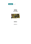
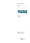
PMGrabber
Hardware Manual
Revision 1A
Revision History
Revision
1A
Changes
First Edition,
valid for Hardware revision 1A,
Date
03.01.2000 AR
WARNING ! This equipment generates and can radiate radio frequencies. If not
installed in accordance with the instruction manual, it may cause interference to radio
communications. The equipment has not been tested for compliance with the limits for
class A computing devices, pursuant to subpart J of part 15 of FCC rules, which are
designed to provide reasonable protection against such interference, but temporary
usage is permitted as per regulations. Operation of this equipment in a residential area
is likely to cause interference, in which case the user, at his own expense is required to
take whatever measures may be required to shield the interference.
DISCLAIMER! The information in this document has been carefully checked and is
believed to be entirely reliable. However, no responsibility is assumed for inaccuracies.
ELTEC reserves the right to make changes to any products to improve reliability,
function or design. ELTEC does not assume any liability arising out of the application or
use of any product or circuit described in this manual; neither does it convey any license
under its patent rights nor the rights of others. ELTEC products are not authorized for
use as components in life support devices or systems intended for surgical implant into
the body or intended to support or sustain life. Buyer agrees to notify ELTEC of any
such intended end use whereupon ELTEC shall determine availability and suitability of
its product or products for the use intended.
ELTEC points out that there is no legal obligation to document internal relationships
between any functional modules, realized in either hardware or software, of a delivered
entity.
This document contains copyrighted information. All rights including those of translation,
reprint, broadcasting, photomechanical or similar reproduction and storage or
processing in computer systems, in whole or in part, are reserved.
EUROCOM is a trademark of ELTEC Elektronik AG. Other brands and their products
are trademarks of their respective holders and should be noted as such.
(c) 1999 ELTEC Elektronik AG, Mainz
Table of Contents
User's Manual
Table of Contents
1
Specification........................................................................... 1—1
1.1
Main Features.................................................................... 1—1
1.2
Technical Details ............................................................... 1—2
2
Connectors............................................................................. 2—1
3
Control LED............................................................................ 3—1
4
Configuring the PMGrabber ................................................... 4—1
4.1
II
Testpoints .......................................................................... 4—2
PMGrabber
User's Manual
Table of Contents
List of Tables
Table 2-1: PMC Connector X 101, X102 ........................................ 2—2
Table 2-2: DigitalOut connector X201 ............................................ 2—3
Table 2-3: Power Connector X602 ................................................. 2—3
Table 2-4: MIN-D connector X601.................................................. 2—4
Table 4-1: Solder Jumper J601, J602 ............................................ 4—1
Table 4-2: Jumper J603.................................................................. 4—1
PMGrabber
III
Table of Contents
User's Manual
List of Figures
Figure 1-1: Block Diagram .............................................................. 1—2
Figure 2-1: Jumper and connector locations .................................. 2—1
Figure 3-1: PMGrabber Frontpanel ................................................ 3—1
Figure 4-1: Testpoints TP601 - TP605 ........................................... 4—2
IV
PMGrabber
User's Manual
Table of Contents
PMGrabber
V
Specification
Specification
User's Manual
1 Specification
1.1 Main Features
•
Two b/w camera inputs for CCIR 625, EIA 525 and non-standard
cameras
•
PixelClock input
•
Opto-decoupled trigger input
Camera control outputs for camera restart and shutter
•
8 Bit look-up table
•
Real-time aquisition of images or image sequences directly into main
memory of host computer
•
8 Bit DigitalOut, intended for use with PMViewer
•
Single size PMC module
•
Power supply for cameras (5V/12V)
•
PCI 2.1 compliant
•
General Description
The PMGrabber is designed to work on a BAB740 (V-BAB.-740) with
additional PMC Carrier (V-PMCE-740) . At this time no further
platform is specified. Please contact ELTEC for more information.
PMGrabber
1—1
Specification
User's Manual
Specification
1.2 Technical Details
The PMGrabber is a Framegrabber for a PCI Mezzanine Card system. The
Grabber based on the PC_EYE®4, and is intended for use with the BAB740
board with additional PMC Carrier (PMCE740).
Figure 1-1: Block Diagram
Camera
Connector
MIN-D
DigitalOut
Video1
Video2
MUX
SyncSeperator
Video
DAC
Color LUT
256 x 8 Bit
Hor. + vert.
Scaler
FIFO
ext. sync
Sync & clock
processing
camctrl
PCI DMAController
5V/12V
Camera
control
PCI-Bus
MultimediaBridge
Cameras are connected via the 15pol.MIN-D connector X601 at the front of
the module. The connector provides all video signals, including camera
control and power.
An input multiplexer permits the use of up to two cameras. The input signal
is separated into sync- and videodata, so the sync- and clock signals for
videoprocessing can be processed to handle a variety of cameras.
The videodata are digitized in an 8-bit A/D-converter and converted by a
LUT with 256 8-bit entries. A small videoprozessor inside the Multimedia
Bridge SAA 7146 permits hardware scalling. Videodata are transfered
1—2
PMGrabber
Specification
directly into the main memory of the host computer. With the optional
PMView graphic module, the digitized data can also be transfered into the
graphics memory via the DigitalOut Connector without loss in performance.
The framegrabber does not have an own image memory apart from a FIFO to
decouple the videostream from the DMA transfer.
The PMGrabber is capable of generating horizontal and vertical or composite
sync signals or up to five programmable control signals (up to two signals at
the MIN-D connector). For this purpose the on-board sequencer is used to
generate control sequences for camera restart, shutter and flash control.
An opto-coupled trigger input can be used to synchronize the acquisition and
the transfer of image data to external events.
PMGrabber
1—3
Specification
User's Manual
Specification
User's Manual
Specification
1—4
PMGrabber
User's Manual
Connectors
2 Connectors
J601
on solderside
J602
DigitalOut
X601
Testpoints
PMC Connectors
X101
X102
MIN-D Connector
X601
D601 SyncDetect
D602 Active
J603
X602
Power Supply
PMGrabber
2—1
Connectors
Figure 2-1: Jumper and connector locations
Connectors
User's Manual
Table 2-1: PMC Connector X101, X102
Connectors
Pin#
1
3
5
7
9
11
13
15
17
19
21
23
25
27
29
31
33
35
37
39
41
43
45
47
49
51
53
55
57
59
61
63
2—2
X101
Signalname
Signalname
nc
-12V
Ground
INTA#
nc
nc
nc
+5V
nc
nc
Ground
nc
CLK
Ground
Ground
GNT#
REQ#
+5V
V(I/O)
AD[31]
AD[28]
AD[27]
AD[25]
Ground
Ground
C/BE[3]#
AD[22]
AD[21]
AD[19]
+5V
V(I/O)
AD[17]
FRAME#
Ground
Ground
IRDY#
DEVSEL#
+5V
Ground
nc
nc
nc
PAR
Ground
V(I/O)
AD[15]
AD[12]
AD[11]
AD[09]
+5V
Ground
C/BE[0]#
AD[06]
AD[05]
AD[04]
Ground
V(I/O)
AD[03]
AD[02]
AD[01]
AD[00]
+5V
Ground
nc
Pin#
2
4
6
8
10
12
14
16
18
20
22
24
26
28
30
32
34
36
38
40
42
44
46
48
50
52
54
56
58
60
62
64
Pin#
1
3
5
7
9
11
13
15
17
19
21
23
25
27
29
31
33
35
37
39
41
43
45
47
49
51
53
55
57
59
61
63
Signalname
+12V
nc
nc
Ground
nc
nc
RST#
3.3V
nc
AD[30]
Ground
AD[24]
IDSEL
+3.3V
AD[18]
AD[16]
Ground
nc
Ground
PERR#
+3.3V
C/BE[1]#
AD[14]
Ground
AD[08]
AD[07]
+3.3V
nc
nc
Ground
nc
Ground
PMGrabber
X102
Signalname
nc
nc
Ground
nc
nc
+3.3V
nc
nc
Ground
AD[29]
AD[26]
+3.3V
AD[23]
AD[20]
Ground
C/BE[2]#
nc
+3.3V
STOP#
Ground
SERR#
Ground
AD[13]
AD[10]
+3.3V
nc
nc
Ground
nc
nc
+3.3V
nc
Pin#
2
4
6
8
10
12
14
16
18
20
22
24
26
28
30
32
34
36
38
40
42
44
46
48
50
52
54
56
58
60
62
64
User's Manual
Connectors
Table 2-2: DigitalOut connector X201
Signalname
DataOut(0)
DataOut(2)
DataOut(4)
DataOut(6)
Reserved (D8)
Reserved (D10)
Reserved (D12)
Reserved (D14)
Ground
HSyncOut
Ground
VSyncOut
Ground
Reserved
Reserved
X201
Signalname
DataOut(1)
DataOut(3)
DataOut(5)
DataOut(7)
Reserved (D9)
Reserved (D11)
Reserved (D13)
Reserved (D15)
Ground
Ground
PixClkOut
Ground
Reserved
Reserved
Reserved
Pin#
2
4
6
8
10
12
14
16
18
20
22
24
26
28
30
Connectors
Pin#
1
3
5
7
9
11
13
15
17
19
21
23
25
27
29
The DigitalOut Port is only for connection with a PMViewer, no further
use allowed.
Table 2-3: Power Connector X602
Pin#
1
3
Signalname
+5V
Ground
X602
Signalname
Ground
+12V
Pin#
2
4
If you intend to supply your camera from the PMGrabber, the internal floppy
type connector X602 has to be used. Use the cable (H-PMGR-800A) coming
with the module to establish a connection with the appropriate connector on
the PMC Carrier. With Jumper J603 (see next chapter) you can select either
5V or 12V as power supply on Pin 15 of the MIN-D camera connector.
PMGrabber
2—3
Connectors
User's Manual
Table 2-4: MIN-D connector X601
Connectors
Pin#
1
3
5
7
9
11
13
15
Signalname
Video1 IN
nc
Ground
Ground
Trigger IN +
Trigger IN Out1 *)
5V/12V OUT
X601
Signalname
Video2 IN
nc
Ground
Ground
Ground
PixelClock IN
Out2 OUT
Pin#
2
4
6
8
10
12
14
* Please refer to Table 4-1
The connector X601 has the same mechanical apperance as an VGA
video output connector. It should not be confused with the latter. To
avoid damage to the hardware, do not connect a VGA monitor to X601.
On Pin 15 of X601 either +5V or +12V are delivered to power the video
camera. The current that can be drawn from this pin is limited by a PTC
resistor ( Imax ca. 500mA). Be sure not interchange 5V an 12V output,
this may cause damages of PMGrabber or video camera.
2—4
PMGrabber
User's Manual
Control LED
3 Control LED
The PMGrabber has two LED that show activation of PMGrabber and the
existence of a sync signal at the camera input.
The LED ACT is controlled bei software. The software activate this LED
with the first access to PMGrabber and has to deactivate it with the last
access.
Control LED
The SYNC LED shows activity on the internal vsync line, if the grabber is
activated. So you have a easy way to control the camera video output and the
use of the right input channel.
VIDEO
SYNC
ACT
Figure 3-1: PMGrabber Frontpanel
PMGrabber
3—1
Control LED
User's Manual
Control LED
3—2
PMGrabber
User's Manual
Configuring the PMGrabber
4 Configuring the PMGrabber
The PMGrabber has 3 jumper for configuring the module for your special
purpose. There are one jumper (J603) for the power supply of the camera and
two solder jumper (J601,J602) to control the function of the dual purpose
Pins 13 (Out1) und 14 (Out2) on the camera connector (X601). The
PMGrabber is capable of generating different video syncronisation signals
and timings. With these jumpers you can either select one of the
programmable sync generator (Hsync, CVSync) outputs or one of the
sequencer controlled output to be routed on the appropriate dualpurpose pin
on the camera connector. Default setting allows the use of the 2 sync
generator outputs at the MIN-D Connector.
Table 4-1: Solder Jumper J601, J602 (Dual purpose pins on MIN-D)
1-2
2-3
J601
MIN-D Pin 14
Hsync
CameraControl 1
1-2
2-3
J602
MIN-D Pin 13
CVSync
CameraControl 2
Table 4-2: Jumper J603 (Power for camera, max . 500mA)
1-2
2-3
J603
MIN-D Pin 15
no power
+12V
+5V
PMGrabber
4—1
Configuring
the PMGrabber
It is not recommended to replace these jumpers. Damages of board may
occur.
Configuring the PMGrabber
User's Manual
4.1 Testpoints
Figure 4-1: Testpoints TP601 - TP605
CameraControl 1
CameraControl 2
CameraControl 3
CameraControl 4
CameraControl 5
Configuring
the PMGrabber
For testing purpose you can use the TP1 - TP5 pads for a soldered connection
of the five sequencer controlled outputs. It is not recommended to use these
pads for permanent connections. Please contact ELTEC if you want to use
this outputs.
4—2
PMGrabber
Configuring the PMGrabber
Configuring
the PMGrabber
User's Manual
PMGrabber
4—3
Germany:
Great Britain:
ELTEC Elektronik AG
Galileo-Galilei-Straße 11
Postfach 42 13 63
D-55071 Mainz
Phone
+49 (6131) 918-0
Fax
+49 (6131) 918-195
ELTEC International PLC 84a
High Street
Stony Stratfort
GB-Milton Keynes, MK111AH
Phone
+44 (1908) 56 22 88
Fax
+44 (1908) 56 39 91
France:
USA:
ELTEC International SARL
1, Allée des Garays
F-91872 Palaiseau Cedex
Phone +33 (1) 64 47 18 77
Fax
+33 (1) 64 47 09 33
American ELTEC, Inc.
101, College Road East
Princeton Forrestal Center
USA-Princeton, NJ 08540-6601
Phone
+1 (609) 4 52 15 55
Fax
+1 (609) 4 52 73 74