1
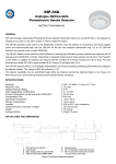
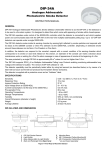
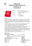
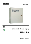
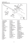
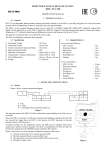
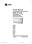
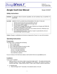
ADDRESSABLE RESETTABLE MANUAL CALL POINT
IPR 513-3PAM
INSTRUCTION MANUAL
1 TECHNICAL DATA
1.1 General
IPR 513-3PAM Addressable Resettable Manual Call Point (hereinafter referred to as the call point or the IPR 513-3PAM) is to be used in fire
alarm and fire extinguishing systems in order to trigger a fire alarm manually or to initiate a fire suppression system.
The call point is to operate under control of a Signal-10 panel in one of its Fire Threshold Addressable Alarm Loops (Type 14). Up to ten call
points (with individual addresses 1 to 10) can be connected to a single alarm loop of the Type 14, each call point being capable of sending the
following messages to the panel: Fire Alarm, Norm, and Trouble. To have more information about operating the call point in the addressable mode,
please refer to the Signal-10 User’s Manual.
The protective transparent flip cover of the call point can be sealed.
The firmware version of the call point is v.1.00. The call point is intended for round-the-clock operation.
1.2 Specifications
1) Alarm Loop Voltage
2) Consumed Current
3) Pre-operation Time
4) Ingress Protection Rating
5) Operating Temperatures
6) Relative Humidity
7) Transportation and Storage Temperatures
8) Overall Dimensions
9) Weight
10) Average Lifetime
-
27 V max
300 uA max
20 s max
IP41
Minus 30°C to +55°C
Up to 93% at 40°C
Minus 50°C to +55°C
95 mm × 91 mm × 33 mm
0.15 kg max
10 years min
1.3 Standard Delivery
For an individual delivery:
– IPR 513-3PAM Manual Call Point
– Instruction Manual
– Special Key
– Woodscrew
– Wall Plug 8×30
– Package
-
1 pc.;
1 pc.;
1 pc.;
2 pcs.;
2 pcs.;
1 pc.
For a group delivery:
– IPR 513-3PAM Manual Call Point
– Instruction Manual
– Special Key
– Woodscrew
– Wall Plug 8×30
– Package
– Group package
-
10 pcs.;
1 pc.;
10 pcs.;
20 pcs.;
20 pcs.;
10 pcs.;
1 pc.
2 OPERATION INSTRUCTIONS
2.1 Wiring
Figure 1 shows a typical schematic for wiring the call point.
Figure 2 shows the view of the call point (without the protective flip cover).
If the call point has been open, a Tamper Alarm message is generated but a Fire Alarm
message cannot be sent.
Figure 1
2.2 Mounting
The call point is to be mounted using the two screws provided to a flat vertical
surface in accordance with your applicable local standards, codes, regulations, and
ordinances.
The wires which pass under the call point should not be clamped by the call point
case.
Figure 2 shows the view of the call point (without the protective flip cover):
1: The hole to insert the key to reset the activated call point;
2: The holes to insert the key to open the call point case;
3: The special key to reset the activated call point and to open its case;
4: The tamper switch of the call point;
5: The button to activate a fire alarm;
6: The place to apply a seal.
2.3 LED Indication
Table 1 describes indication of the operation modes of the call point.
Figure 2
Table 1
LED Behavior
Flashing once per 8 seconds
Double flashing once per 8 seconds
Triple flashing once per 8 seconds
Triple flashing (blinking) once per 2 seconds
Four-time flashing once per second
Condition (Event)
Norm
Fire Alarm
Tamper Alarm or Trouble
In an addressable alarm loop non-programmed (factory) address is indicated
Connecting to a non-addressable alarm loop or dc voltage.
Waiting for assigning an address
2.4 Programming a Call Point Address
For operation, the call point has to be assigned to an address in the range of 1 to 10.
The call point is delivered with no address. If a call point with non-assigned address is wired into an addressable alarm loop, the LED indicator
blinks once per two seconds.
Assigning an Address. Connect the call point with its cover removed into a disarmed alarm loop of the Type 1 of the Signal-10 panel or to a
10 V to 12 V power supply. In 6 s four-time flashing of the LED once per second means that the call point is ready to receive an address. Press the
tamper switch and hold until the LED is lit steady, then release the tamper switch. Press the tamper switch again so many times as the relevant
address is (one to ten times). In 5 s the LED shall flash the number of times equal to the assigned address and light for a half of a second.
Auto Assigning to a First Vacant Address of a Loop. Connect the call point with its cover removed into an addressable alarm loop of the
Signal-10. In 20 s press on the button which activates fire alarms. In about 6 s the LED switches on for 1 s and then switches off. The address has
been assigned.
Requesting for the Address. Connect the call point with its cover removed into a disarmed alarm loop of the Type 1 of the Signal-10 panel or to
a 10 V to 12 V power supply. In 6 s four-time flashing of the LED once per second means that the call point is ready to receive an address. Press the
tamper switch and hold until the LED is lit steady, then release the tamper switch. In 5 s the LED shall flash the number of times equal to the
assigned address and light for a half of a second.
2.5 Routine Testing
2.5.1 Before testing the call point, please disconnect executive outputs of all system devices and modules that can release an extinguishing
agent or activate light and sound alarms. Notify the proper authorities that the system is undergoing maintenance.
2.5.2 Arm the alarm loop of the Signal-10 with the connected call point, the last one being indicating its Norm status by flasing once per 8 s.
2.5.3 Activate the call point by pressing the key. The Signal-10 shall indicate the fire alarm for the given address, the call point LED double
flashing every 8 s.
2.5.4 Reset the call point to its Norm state by inserting the special key provided. Ensure the call point LED starts flashing once per 8 s. From
the console or PC issue a command to cancel the alarm from the call point.
If the Fire Alarm message is not received by the console or PC, the call point is unhealthy and must be replaced.
2.5.5 Repeat steps 2.5.2 – 2.5.4 mimimum three times.
2.5.6 After testing verify that the call point is ready to operate properly. Then restore operability of all the system components disconnected
before testing and notify the proper authorities that the system is back in operation.
2.5.7 Test the call point operability at least once per three months.
All the equipment used in testing must be known functioning.
ZAO NVP Bolid, 4 Pionerskaya Str., Korolev 141070, Moscow Region, Russia
Phone/fax: +7 495 775-7155
Email: [email protected]
Technical Support: [email protected]
http://bolid.ru