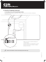
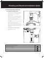
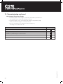
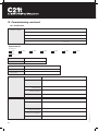
1
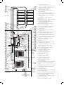
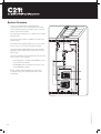
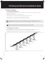
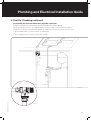
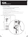
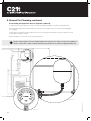
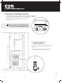
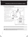
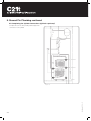
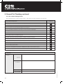
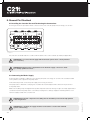
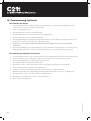
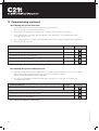
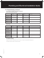
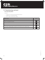
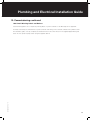
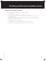
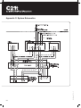
Part Number 10120—01
Plumbing and Electrical Installation Guide
For new build only, to commence after installation of the C21t tiles.
This guide must be left with the property owner after installation.
Issue: 02:December 08
© Solarcentury 2008
1 C21t Solar Thermal Roof Tile
3
1
4
2
5
2 Compression Straight Coupling,15 mm x 15 mm
3 Compression, Equal Tee Coupling 15 mm
4 Compression Straight Coupling,
15 mm x 0.5 in BSP Female
5 Sensor Pocket, Brass-chromed 60 mm
x 0.5 in BSP Male
7
6 Collector Temperature Sensor (FRP6)
7 Collector Temperature Sensor (FKP6) Black
8 Collector Sensor Connection Box with Over Voltage Protection
Loft void
9 Flow Meter 0.6 – 2.4 Litres Per Minute
Range 15 mm
10 Expansion Vessel 18 Litre, 10 Bar, 120 Degrees C
9
11 Compression Straight Coupling
15 mm x 0.75 in BSP Male with High Temperature Sealing Ring
8
12 Pre-assembled Single Line Pump Station (Flowcon A – Deltasol BS/3)
11
25
26
27
18
3
12
14 Pressure Relief/Safety Valve Supplied
on Pump Station
14
15 Filling and Flushing/Drain Valve Supplied
on Pump Station
13
16 Solar Thermal Pump Supplied on Pump Station
27
18 Integrated Differential Temperature Controller (Deltasol BS/3) Supplied on Pump Station
20
21
43
22
13 Pressure Gauge Supplied on Pump Station
15
17 Flow Meter Supplied on Pump Station
19 Compression Straight Coupling 22 mm x 0.75 in BSP Male with High Temperature Sealing Ring. Sensor Pocket, Brass-chromed 60 mm x 0.5 in BSP Male
20 Flexible Hose
24
10
23
16
42
17
36
15
24 Vertical Solar Deaerator 10 Bar, 180ºC,
22 mm x 22 mm
34
19
25 Pressure Relief/Safety Valve, High Temp
0.5 in x 0.75 in BSP, 6 Bar
38
6
26 Compression Straight Coupling,
15 mm x 0.5 in BSP Male
40
30
22 Compression, Stop End 15 mm
23 Compression, Reducing Set 22 mm to 15 mm
27 Compression Straight Coupling,
22 mm x 0.75 in BSP Male
Boiler
primary
heating
circuit
29
21 Isolating Valve with Handle 15 mm x 15 mm
28 Tundish 0.75 in
29 Compression Reducing Tee
22 mm x 22 mm x 15 mm
31
30 Compression Straight Coupling,
15 mm x 0.5 in BSP Female
32
31 Sensor pocket, Brass-chromed
60 mm x 0.5 in Male
37
32 Heat Quantity Temperature Sensor (FKP6) Black
28
35
41
33 Drain Valve, 15 mm Plain Shank MT Plug Type A
34 Upper Store/Cylinder Temperature Sensor (FRP6)
35 Lower Store/Cylinder/Return Temperature Sensor (FRP6)
Cylinder
Cupboard
PRV (vented
to comply
with local
plumbing
regulations)
Lower floor
Cold
Water
feed
Hot
Water
Supply
36 Junction Box x 10-way
37 Twin Coil Unvented Stainless Steel Cylinder Kit
38 Sensor Grommet (Grey)
39 Solar Hot Water System Fluid (Concentrate) (10L)
40 Two Port Valve (Solar Energy Cut Out Valve) (may be supplied in cylinder)
41 Dual Thermostat (may be supplied in cylinder)
42 Switched Fused Spur 5A
2
43 Expansion vessel servicing coupling
Part Number 10120—01
33
Plumbing and Electrical Installation Guide
This guide provides a step-by-step overview for the installation
and commissioning of the plumbing and electrical components
of a standard C21t solar thermal roof tile (solar hot water /
SHW) system.
8.3 Installing the Expansion Vessel
(Cylinder cupboard)................................................ 24
It is intended for systems of up to 32 C21t tiles connected to an
unvented mains pressure cylinder.
8.5
8.6 Installing the Drain Cock (Cylinder cupboard)......... 26
For other system configurations please consult Solarcentury.
8.7 Installing the Deaerator (Cylinder cupboard)........... 27.
8.8 Completing the Cylinder Connections
(Cylinder cupboard)................................................ 28
Contents
Symbols and Notification Used.......................................... 4
1. Health and Safety Considerations................................ 5
2. General Guidance........................................................... 6
2.1 System Overview..................................................... 6
2.2 Skills Required......................................................... 7
3. Quick Installation Guide................................................ 8
Installing the Energy Cut-out Valve........................ 26
8.9 Flushing the System............................................... 29
8.10 Pressure Testing the Complete Solar Circuit........... 29
8.11 Pre-commissioning Checks.................................... 30
9. Second Fix: Electrical................................................... 31
9.1 Installing the Sensors and Connecting to the
Solar Controller...................................................... 31
4. Installation Checklist..................................................... 9
9.2 Installing the Junction Box and Terminating
the Connections..................................................... 32
4.1 Solarcentury Parts Supplied..................................... 9
4.2 Tools Required....................................................... 10
10. Commissioning............................................................ 33
4.3 Consumables Required.......................................... 10
10.1 Confirming Pre-commissioning Checks.................. 33
4.4 Optional Items........................................................ 10
10.2 Hydraulic Commissioning Procedure...................... 33
9.3 Connecting the Mains Supply................................. 32
5. First Fix: Plumbing....................................................... 11
10.2.1 Volume of Fluid and Flow Rates............... 33
5.1 Solar Circuit and Connection.................................. 11
10.2.2 Pre-filling Checks..................................... 33
5.2 Tile Connections and Checks................................. 11
10.2.3 Connecting the Jet pump filling unit.......... 34
5.3 Connecting the Flow Meters (Roof void)................. 14
10.2.4 Wet Pressure Testing the System at 6 Bar... 35
5.4 Connecting the Tile Temperature Sensor
Assembly (Roof void).............................................. 15
10.2.5 Venting the System.................................. 36
5.5 Running the Pipe Work to the Cylinder Cupboard.... 16
10.2.7 Venting the System Pump........................ 37
5.6 Installing the Pressure Relief Valve
(Cylinder cupboard)................................................ 17
10.2.8 Setting the System Flow Ratess............... 38
5.7 Installing the Pressure Testing Filling Assembly
Cylinder cupboard)................................................. 18
10.3 Electrical Commissioning Procedure..................... 39
5.8 Pressure Testing the Solar Array
(Cylinder cupboard)................................................ 19
10.3.2 Control Thermostat Testing...................... 40
6. First Fix: Electrical......................................................... 20
6.1 Installing the 5A fused spur.................................... 20
6.2 Installing the collector temperature sensor
extension kit........................................................... 20
Part Number 10120—01
8.4 Installing the Heat Quantity Meter Sensor Pocket
(Cylinder cupboard)................................................ 25
7. Cylinder Installation...................................................... 21
8. Second Fix: Plumbing................................................... 22
8.1 Installing the Pump Station (Cylinder cupboard)...... 22
8.2 Installing the Pressure Relief Valve and Tundish
(Cylinder cupboard)................................................ 23
10.2.6 Venting the Individual Tile Columns.......... 36
10.2.9 Setting the System Cold Fill Pressure....... 38
10.3.1 Sensor Testing......................................... 39
10.3.3 Setting the Control Unit Parameters......... 41
10.3.4 Checking the Delta t Operation................ 42
10.4 System Testing....................................................... 43
10.5 Insulating the Pipe Work . ...................................... 44
10.6 Attaching Warning Labels and Notices .................. 45
10.7 Certification............................................................ 46
Appendix A: Basic System Troubleshooting Guide.............. 48
Appendix B: Draining the System........................................ 49
Appendix C: System Schematics........................................ 50
3
Symbols and Notification Used
The following symbols are used throughout this document:
A triangle with an exclamation mark indicates a general warning. The text adjacent to the symbol will
contain important information relating to safety or refer to a procedure that should be followed to prevent
risk of injury or damage to any part of the installation.
A triangle with the ‘HEAT’ symbol indicates a warning relating to a heat hazard—
e.g. a risk of burn or scald.
A triangle with the ‘FLASH’ symbol indicates a warning relating to an electrical hazard—
e.g. a risk of electrical shock.
This symbol indicates that a warning label should be applied at this stage.
A circle with an ‘i’ indicates that further information is available in the manufacturers’ manuals or other
documentation supplied with the system.
A tick indicates a tip that could make installation easier.
4
Part Number 10120—01
Sections 8 to 10 MUST be completed by the Installer/Commissioning Engineer.
Plumbing and Electrical Installation Guide
1. Health and Safety Considerations
IMPORTANT—READ THIS SECTION FIRST
Solar thermal collectors and systems are not always readily identifiable within a building structure or heating system and can
represent a significant risk of burns and heat damage if not treated properly.
The collector array should be accessible to competent persons only.
Solar absorbers and their pipe connections are capable of reaching temperatures approaching 200°C.
Installation and operating instructions must be read and understood before conducting any work on the system.
Always take care. If you have any queries, ask an experienced solar installer or engineer for guidance.
Temperature
Severe burns can result from contact with the surfaces of some elements of the C21t system:
• Metal parts left in direct sunlight can reach temperatures of up to 80°C.
• The absorber surface within a C21t tile can reach temperatures approaching 200°C.
• Conduction heat transfer will cause other parts of the C21t tile and pipe work to reach similar high temperatures.
Conversely, in cold weather, metal components can become very cold.
Pressure
The C21t system should not pose a risk to users as long as it has been installed correctly. However, if it is installed incorrectly,
there is a risk that severe burns or scalds could result from contact with liquid and/or vapour escaping from the system.
• When the solar hot water circuit is filled and pressurised, the heat transfer liquid may be heated to its boiling point
and vaporise.
• Improper system design or installation may lead to discharges from pressure relief valves, faulty couplings or joints. System Fluid
The system fluid is non-toxic when diluted to its correct mix of 40% glycol antifreeze and 60% water.
WARNING: Do not mix system fluids from different manufacturers.
Access
A safe means of access and a safe working environment, including protection from falls, should be established before any work
is carried out on the system.
2. General Guidance
About this Guide
• Provides the information to enable a competent plumber or solar installer, who is already familiar with the basic system components, to undertake the installation of the plumbing and solar controller components.
• Provides a suitably qualified plumber with guidance for connecting to the mains pressure hot water cylinder.
• Provides a fully qualified electrician with guidance for connecting the AC mains supply.
Part Number 10120—01
WARNING: Check that the C21t tiles already installed comply with the system design guide.
If they do not, seek advice from the system designer before proceeding.
5
System Overview
The C21t solar thermal tiles and related system
components form a solar hot water (SHW) system that
collects thermal energy from sunlight and uses it to heat
water in the hot water cylinder.
The system uses a heating coil in a similar way to a typical
domestic boiler.
Hot water from the cylinder is supplied to the taps in the
normal manner.
The system can be supported with other sources of heat
such as a gas, oil or an electrical immersion heater.
The system works independently alongside the existing
heating/hot water systems, but uses the same vessel for
heat storage.
The rooftop SHW tiles, can be treated much like any other
source of heat, such as a boiler:
• The FLOW refers to the pipe work FROM the source of the heat TO the cylinder.
• The RETURN refers to the pipe work TO the source of heat FROM the cylinder.
Use the cylinder cupboard template to ensure there
is sufficient space in the cylinder cupboard for all the
components.
6
Part Number 10120—01
Diagram 1
Plumbing and Electrical Installation Guide
IMPORTANT: All connections in the solar circuit MUST be made using compression fittings.
Solder connections are unsuitable because the solar circuit reaches temperatures significantly higher
than traditional plumbing.
Silver solder does meet the temperature requirements. However, the use of flux necessitates additional
thorough flushing of the system prior to commissioning.
Skills Required
All components must be installed by competent persons suitably qualified and trained.
Components should be installed in accordance with the system schematic supplied and also with the relevant British Standards
and Codes of Practice.
Installers should be trained in ‘Safe Working at Height’ and ‘Safe Ladder Use’.
Plumbing, solar controller components and cabling should be undertaken by a competent plumber or UK Registered
SHW Installer.
Mains pressure unvented hot water cylinder installation must be undertaken by a plumber trained to the Part G3 regulations.
For the AC mains fuse spur installation, the cabling and connection to the pump station must be undertaken by an electrician
qualified to Part P regulations.
Final system commissioning should be undertaken by a UK Registered SHW Installer, ideally trained to BPEC, Corgi or IPHD.
WARNING: The internal parts of an SHW tile will get hot when the tile is exposed to direct sunlight.
During very hot weather, the flexible steel hoses may get hot even before the system is fully connected.
When the SHW system is filled and pressurised the heat transfer liquid may be heated to its boiling
point and vaporised. Improper system design or installation could lead to discharges from pressure relief
valves, faulty couplings and pipe work leaks. Severe burns may result from contact with the escaping
liquid or vapour.
Part Number 10120—01
The standards for installation quoted in this guide are correct at the time of printing. Always refer to the latest
relevant standards.
7
3. Quick Installation Guide
The installation process can be viewed as four stages:
• First Fix (Plumber and Electrician)
• Cylinder Installation (Plumber)
• Second Fix (Plumber and Electrician)
• Commissioning (Plumber and Electrician)
First Fix: Plumber
First Fix: Electrician
• Join the C21t tiles into columns
• Join the columns of tiles into the final array
• Install the collector temperature sensor
extension kit
• Fit the column flow meters and sensor pocket assembly to complete the solar array
• Run cable for the fused spur to the cylinder cupboard
• Bring flow and return pipe work to the
cylinder cupboard
• Fit the supplied pressure relief valve and pressure testing filling assembly
• Pressure test the tile array (using either air or
solar fluid)
• Drain the system (reclaiming the fluid for use
at a later stage)
Second Fix: Plumber
Second Fix: Electrician
• Install the pump station
• Install the expansion vessel
• Install the four system sensors and run the
collector sensor cable to the cylinder cupboard
• Install the heat meter sensor pocket
• Install the energy cut-out valve
• Install the drain cock
• Install the deaerator
• Make the cylinder connections
• Terminate the pump station and solar
controller connections
• Terminate the 5A fused spur
• Pressure test the complete circuit and drain
down the system (reclaiming the fluid for use at
a later stage)
• Pre-commissioning checks
• Hydraulic commissioning
• Electrical commissioning
• System test
• Pipe work insulation
• Attach warning labels and notices
• Return a copy of the Commissioning Certification
to Solar Century.
8
Part Number 10120—01
Commissioning
Plumbing and Electrical Installation Guide
4. Installation Checklist
Before proceeding with the installation:
• Check that you have all the required parts supplied by Solarcentury.
• Check that you have the necessary tools and consumables required for the installation.
Depending on the location of the cylinder cupboard, you may need to order additional items from Solarcentury.
Solarcentury parts supplied
The following items are supplied:
Pack, C21t Loft Box
Item #
Description
Quantity 1
Sensor pocket, RESOL brass-chromed 60 mm X 0.5” BSP
1
2
Compression equal tee 15 mm
1
3
Compression straight coupling, 15 mm X 0.5” BSP female
1
Part Number 10120—01
Pack, C21t System Box
4
SHW system fluid, (concentrate) 10 L
1
5
Exansion vessel wall bracket and hose (for 10225-01)
1
6
Expansion vessel, 18 L 10 BAR 120°C
1
7
Pumpstation, RESOL flowcon A—DeltaSol BS/3
1
8
Deaerator, Sprirovent vertical 10 BAR 180°C 22 mm X 22 mm
1
9
C21t Cylinder cupboard template
1
10
C21t Laminated system schematic (GB)
1
11
C21t Laminated wiring control schematic (GB)
1
12
Home operation and maintenance guide (GB)
1
13
C21t Plumbing installation guide (GB)
1
14
Sensor grommet (grey)
1
15
Junction box, RESOL (including over-voltage protection)
1
16
Junction box, Honeywell 10-way
1
17
Temperature sensor, RESOL FRP6 with 2.5 m cable
3
18
Temperature sensor, RESOL FKP6 with 2.5 m cable
1
19
Cable, temperature sensor extension (10 m)
1
20
Pressure relief valve, high temperature 0.5” X 0.75” BSP 6 BAR
1
21
Tundish 0.75” BSP
1
22
Compression straight coupling, 22 mm X 0.75” BSP male
2
23
Compression straight coupling, 15 mm X 0.5” BSP male
1
24
Compression reducing tee, 22 mm X 22 mm X 15 mm
1
25
Drain valve, 15 mm plain shank MT plug type A
1
26
Sensor pocket, RESOL brass-chromed 60 mm X 0.5” BSP
1
27
Compression straight coupling, 15 mm X 0.5” BSP female
1
28
Compression isolating valve, 15 mm with handle
1
29
Compression stop end, 15 mm
1
30
Compression reducing set, 22 mm to 15 mm
1
31
Compression equal tee, 15 mm
1
32
Compression straight coupling, 22 mm X 0.75” BSP male with high temperature seal
1
33
Compression straight coupling, 15 mm X 0.75” BSP male with high temperature seal
1
9
4. Installation Checklist continued
The components listed above remain the same for all system configurations up to and including 32 C21t tiles.
The number of couplings that connect the tiles, the amount of high temperature insulation and the number of flow meters
supplied can be calculated as follows:
C21t tiles (t)
12
16
20
24
28
32
Array columns (c) x rows (r)
2 x 6
2 x 8
4 x 5
4 x 6
4 x 7
4 x 8
Tile hose insulation
Column flow meters
lengths (metres)
24
2
32
2
40
4
48
4
56
4
64
4
Hose couplings (C) C=t-1+c
13
17
23
27
31
35
Tools required
• Standard set of plumbing tools.
• Air pump with Schrader valve connection (a foot pump or cycle track pump is ideal)
• Either a dry test kit with Schrader valve and 15 mm push fit fitting or a wet pressure test kit
• Jet pump filling unit
Consumables required
• 5A switched, fused spur
• Ø15 mm / Ø22 mm copper pipe for fitting the connection between the roof and cylinder location
• Metal pipe clips (not plastic)
• PTFE (Teflon) tape
• High temperature pipe insulation (rated to at least 150˚C) for the pipe work between the roof, pump station and cylinder
• Suitably rated compression fittings for the pipe runs.
Optional items
Depending on the location of the cylinder cupboard relative to the C21t tiles, and the space available in the cylinder cupboard,
you may need to purchase the following additional items:
• Fittings for remote location of the expansion vessel
• Additional sensor cable
• Manual air vents
• Additional high temperature pipe insulation
• Suitable twin coil cylinder (this is only required if you have not purchased a hot water cylinder with the Solarcentury system)
10
Part Number 10120—01
Please contact Solarcentury if additional components or spares are required.
Plumbing and Electrical Installation Guide
5. First Fix: Plumbing
5.1 Solar Circuit and Connection
The C21t solar thermal roof tiles are connected together in series to form columns using pre-fitted flexible hoses and suitably
rated brass compression fittings.
All multiple columns installed are connected together in parallel.
The flow and return are connected back to the pump station and cylinder within the building.
If required, PTFE tape is recommended instead of paste on fittings and connections.
Note that compression coupling manufacturers state that no tape or paste is required.
WARNING: Failure to follow this guidance may cause damage to equipment or injury to installers or users.
Refer to the Solarcentury system schematic and wiring control schematic provided.
5.2 Tile Connections and Checks
When completing the C21t solar thermal roof top installation, the roofer feeds the inlet and outlet hose from each C21t tile
through membrane collar. These hoses are left hanging in the roof void for connection by the plumber
For further details about the roof installation processes refer to the C21t Solar Thermal Roof Tile—On Roof Installation Guide.
Blue
Red
Blue
Red
Blue
Red
Blue
Red
Blue
Red
Blue
Part Number 10120—01
Red
Diagram 2
11
5. First Fix: Plumbing continued
5.2 Tile Connections and Checks continued
There are two hoses for each tile; one flow and one return.
The hoses are fitted with plastic end caps to protect the stub and prevent dirt or debris entering the end of the hose.
The end of each FLOW hose will be marked with a RED end cap.
The caps can now be removed.
For each column of tiles:
• The flow and return from each tile should be connected in series with the tile above and below.
• The flow from each tile should point upwards to connect with the return of the tile above.
• For each column of C21t tiles, there should be an unconnected flow hose at the top and an unconnected return hose
at the bottom.
For the system configurations included in this guide, there are a maximum of eight and a minimum of five C21t tiles
per column.
Before the hoses are connected, check:
• That there are the correct number of hoses entering the loft void.
• Ensure the membrane collar is seated correctly. The neck of the collar should point upwards to prevent penetration of water.
• Which are the flow and return for each C21t tile.
• That none of the hose ends have been damaged during installation (do NOT proceed with installation until any damage
has been remedied).
• Check that the high temperature insulation hoses are installed and pushed up far enough to meet the roof membrane.
Use the compression fittings supplied to connect the tiles in series.
12
Part Number 10120—01
Diagram 3
Plumbing and Electrical Installation Guide
5. First Fix: Plumbing continued
5.2 Tile Connections and Checks continued
Leave the flow and return hoses at the top and bottom of each column un-connected.
Diagram 4
WARNING: Avoid forming kinks or using excessive force to bend the hoses during connection and
installation because it could strain a plumbing connection within the C21t tile or rip the roofing membrane
or membrane collar, both of which could cause a roof leak.
Part Number 10120—01
WARNING: Care should be taken when manipulating the hoses to make connections.
There is a risk that the hoses may spring back and cause damage or injury.
13
5. First Fix: Plumbing continued
5.3 Connecting the Flow Meters (Roof void)
Within the roof void, fit a flow meter on the return pipe work in an easily accessible position (diagram 5).
The flow meter may be connected directly to the tile hose.
Ensure that the flow direction arrow on the body of the flow meter points towards the tile (diagram 5a).
Check that the flow meters are set to fully open setting. Adjust if necessary.
Diagram 5
A
B
D
F
D
A
B
2 .4
2
1 .5
1
0 .6
flow
Diagram 5a
14
Part Number 10120—01
TIP: If the location of the lowest tile means that the flow meter cannot be easily read, the tile hose can
be extended with 15 mm pipe work so that the flow meter is located in a visible position. The number of
compression fittings supplied allows for this (Diagram 5).
Plumbing and Electrical Installation Guide
5. First Fix: Plumbing continued
5.4 Connecting the Tile Temperature Sensor Assembly (Roof void)
Fit the collector temperature sensor assembly at the top of the first column of tiles using brass compression fittings.
The first column is the one on the far right (or far left if this helps reduce the cable run to the solar controller) when
viewed from within the loft void.
Diagram 6
Diagram 6a
TIP: Fit the assembly only.
The sensor will be fitted during the second fix electrical installation (see 9.1).
Part Number 10120—01
Refer to the Solarcentury system schematic provided for connection details.
WARNING: Solder joints must NEVER be used in the loft void due to increased fire risk.
All joints in the loft void MUST be brass compression fittings.
Solder joints cannot withstand the high temperatures of the solar circuit.
15
5. First Fix: Plumbing continued
5.5 Running the Pipe Work to the Cylinder Cupboard
Connect the columns of tiles in parallel to a common flow and return.
It is recommended that all flow and return pipe work is 15 mm diameter copper.
Flow and return pipe work should fall steadily from the tiles back to the cylinder location.
If this is not possible, ensure that manual air vents are fitted to vent any trapped air during commissioning.
Diagram 7
16
Part Number 10120—01
WARNING: All joints in the loft void MUST be brass compression fittings.
Solder joints cannot withstand the high temperatures of the solar circuit.
Plumbing and Electrical Installation Guide
5. First Fix: Plumbing continued
5.6 Installing the Pressure Relief Valve (Cylinder cupboard)
A 6 bar pressure relief valve must be fitted from the flow pipe within the cylinder cupboard.
This will allow the pressure test to be completed and then vented to a drain as part of the first fix installation.
Compression connections to threaded BSP adaptors are supplied for connecting the valve into the solar circuit:
• The 15 mm fitting allows connection from the 15 mm flow pipe.
• The 22 mm fitting allows connection to the 22 mm vent pipe.
Part Number 10120—01
Diagram 8
Diagram 8a
17
5. First Fix: Plumbing continued
5.7 Installing the Pressure Testing Filling Assembly
Install the pressure testing filling assembly within the cylinder cupboard. Use the 15 mm equal tee, isolating valve
and end stop provided.
Diagram 9
All pipe work must be secured with metal pipe clips
to avoid movement.
Diagram 9a
The clips should be spaced at approximately one meter
intervals. This leaves space for insulation to be fitted
following commissioning.
18
Part Number 10120—01
TIP: Do not fit insulation to the flow and return pipe work at this stage.
Plumbing and Electrical Installation Guide
5. First Fix: Plumbing continued
5.8 Pressure Testing the Solar Array (Cylinder cupboard)
Check the tile circuit connections with either a dry (air) or
wet (solar fluid) pressure testing kit.
The flow and return pipe work will need to be temporarily
capped for the pressure testing (the system kit does not
include stop end couplings for this purpose).
The tile connection circuit should be pressure tested to
6 bar (determined by the pressure relief valve).
If wet pressure testing:
• Ensure that only the supplied Glycol-Antifreeze solar fluid
is used. This must be diluted in a 40:60 mix with water.
• Ensure that the whole solar circuit is drained after testing
and left open.
Any connections that fail should be checked in detail to
identify and then remedy the fault (the most common fault
is a poorly tightened fitting, which can be easily rectified).
Diagram 10
WARNING: All pressure testing MUST satisfy the local health and safety legislation.
WARNING: Failure to undertake a pressure test or to take heed of a pressure test failure could result in
failure of the system at a later stage.
Part Number 10120—01
TIP: If wet pressure testing, you may wish to save the diluted solar fluid when draining the system so that
you can use it in the next phase of installation.
19
6. First Fix: Electrical
6.1 Installing the 5A fused spur
A 13A 2.5 m twin and earth cable needs to be spurred from the ring main to the cylinder cupboard.
This will feed the 5A fused spur installed during the second fix.
6.2Installing the collector temperature sensor extension kit
The collector temperature sensor is supplied as standard with a 1.5 m cable.
On the assumption that the 1.5 m cable may not reach the solar controller on the pump station, an extension kit has
been supplied consisting of a junction box (Diagram 11), which has integrated over-voltage protection, and a 10 m
extension cable.
When installing the extension kit:
• The sensor cable should be fitted with and follow the same route as the flow and return pipe work back to the pump
station location.
• The cable can be tied to the outside of the INSULATED return pipe work (it must not be tied directly to
non-insulated pipe work).
• The junction box should be fixed at a convenient secure location on a rafter or joist in the loft void.
20
Part Number 10120—01
Diagram 11
Plumbing and Electrical Installation Guide
7. Cylinder Installation
The following guidance provides a general overview for cylinder installation. If your cylinder has not been provided by
Solarcentury, you must refer to the separate instructions provided by the cylinder manufacturer for specific details.
It is usual to locate the cylinder, pump station and the expansion vessel together in a dedicated cylinder or
airing cupboard within the building.
Fix the supplied cylinder cupboard template to the wall of the installation area. This will indicate the relevant position of
all the components of the solar system that must be located in the cupboard in addition to the cylinder itself.
The system designer will have decided the suitability of the installation using the C21t System Design Guide, however,
before proceeding with the cylinder installation, you should confirm that:
• The proposed system design is indirect; water is heated via a heat exchange coil within an unvented water heating cylinder.
• The vertical distance between the cylinder location and the top of the C21t tiles is less than 8 m.
• There is sufficient room to install the cylinder.
• There is sufficient room to make all the required connections once the cylinder is installed (this will reduce complicated
pipe runs).
• The cylinder contains two coils:
The solar flow and return must be connected to the lower coil.
The upper coil is used by the auxiliary heat source (e.g. the boiler).
• If the coils in the cylinder have a single helix:
The flow enters the cylinder at the upper inlet of the lower coil.
The return exits at the lower outlet.
• There is a suitable vertical surface adjacent to the cylinder to mount the pump station and the 18L expansion vessel.
Contact your system designer if you cannot confirm any of the above points or if you have any queries.
The expansion vessel can be fitted in the roof void if there is not enough room for it in the cupboard. Additional fittings
to those supplied with the system will be required to achieve this.
WARNING: Mains pressure unvented cylinders must be installed by a plumber qualified to
Part G3 regulations*.
Part Number 10120—01
Fit the cylinder in accordance with the instructions provided in the user manual supplied with the unit.
*Regulation quoted is correct at time of going to print.
21
8. Second Fix: Plumbing
The remaining solar circuit is completed in stages 8.1 to 8.9 as described in the following pages.
This process will finish with you making the connections to the cylinder and flushing the system.
8.1 Installing the Pump Station (Cylinder cupboard)
Compression to threaded BSP fittings are supplied for connecting the pump station into the solar circuit:
• The 22 mm fitting allows connection from the cylinder.
• The 15 mm fitting allows connection to the 15 mm return pipe to the tiles.
Be sure to use the high temperature sealing ring with the fittings supplied for both connections.
Position the pump station close to the cylinder in the cupboard so that the sensor cables and power cable can be run into it
without interfering with the cover when refitted.
Position the pump station to ensure that all the connections and the front face of the pump station are visible and easily
accessible for future maintenance.
Mount according to the instructions supplied with the pump station.
DN15
2
3
4
1
5
0
6
Diagram 12
Diagram 12a
22
Part Number 10120—01
l/min
13
11
9
7
5
3
1
Plumbing and Electrical Installation Guide
8. Second Fix: Plumbing continued
8.2 Installing the Pressure Relief Valve and Tundish (Cylinder cupboard)
There are two pressure relief valves. One was installed in section 5.6; the other is integral to the pump station.
Both need to be vented to a 28 mm or adequate diameter drain via a tundish.
Diagram 13a
DN15
2
3
4
1
Diagram 13b
5
0
6
Diagram 13
Part Number 10120—01
Diagram 13c
WARNING: A 22 mm pipe should be fitted from the pressure relief/safety valves to the vent pipe,
before the tundish, to comply with UK plumbing regulations.
23
8. Second Fix: Plumbing continued
8.3 Installing the Expansion Vessel (Cylinder cupboard)
Locate the position of the expansion vessel on the cylinder cupboard template to the right of the pump station.
Be sure that the pump station and the expansion vessel are close enough to allow for connection with the flexible
hose supplied.
Confirm and/or set the pressure in the expansion vessel to 1.5 bar before mounting the vessel. The expansion vessel
is normally pre-charged to 2.5 bar.
Mount the expansion vessel and connect to the pump station.
Specific pump expansion vessel mounting requirements vary from one model to another. The equipment
must be secured in accordance with the instructions provided in the user manual supplied with the unit.
DN15
2
3
4
1
5
0
6
Diagram 14
Diagram 14a
13
11
9
7
5
3
1
l/min
24
Part Number 10120—01
Diagram 14b
Plumbing and Electrical Installation Guide
8. Second Fix: Plumbing continued
8.4 Installing the Heat Quantity Meter Sensor Pocket (Cylinder cupboard)
Fit a temperature sensor pocket assembly in the 22 mm return just below the pump station.
The actual sensor will be fitted at a later stage (see section 9.1).
Having a temperature sensor fitted to the return pipe work is necessary to enable the
total thermal energy yield (kWh) to be recorded.
Diagram 15a
Part Number 10120—01
Diagram 15
25
8. Second Fix: Plumbing continued
8.5 Installing the Energy Cut-out Valve (Cylinder cupboard)
If required by your cylinder provider, the cut-out valve should
be fitted on the 22 mm return pipe between the cylinder
and the pump station.
The cut-out valve should be supplied with the
cylinder (if required). For installation instructions
refer to the user manual supplied with the unit.
Diagram 16
8.6 Installing the Drain Cock
(Cylinder cupboard)
The drain cock supplied should be fitted at the lowest
point closest to the cylinder in the pipe returning to the
pump station.
This will enable the whole system to be drained down,
if necessary, for maintenance (see appendix B).
26
Diagram 17a
Part Number 10120—01
15
Diagram 17
Plumbing and Electrical Installation Guide
8. Second Fix: Plumbing continued
8.7 Installing the Deaerator (Cylinder cupboard)
The solar circuit will contain a small amount of gas in the
form of air pockets and micro-bubbles even after
conventional air venting at commissioning.
The solar deaerator enables both free flowing air and microbubbles to be vented from the diluted solar fluid during
system operation. By doing so it:
• Helps optimise system performance.
• Enables quieter operation.
• Lengthens system component life.
The deaerator is fitted close to the
cylinder on a vertical section of
the flow pipe.
The flow pipe from the tiles is
15 mm diameter. Therefore a
22 mm to 15 mm reducing adaptor
is supplied to connect to the 22 mm
inlet of the deaerator. A 22 mm pipe
can then be used to connect from the
outlet of the deaerator to the
Diagram 18a
cylinder inlet.
An end cap needs to be fitted to the vent at the
top of the unit if the system is to be pressure tested with
air. This should be left in place until the whole solar circuit
has been pressure tested and then removed before final
commissioning with correctly diluted solar fluid.
Diagram 18
TIP: If the end cap is removed before the dry pressure test, the system will not hold pressurised air.
Part Number 10120—01
WARNING: The solar deaerator weighs approximately 2 kg and is supported by the pipe work it is
connected to. Therefore the pipe work either side of the solar deaerator must be properly secured,
using metal clips, to adequately support the deaerator’s weight.
27
8. Second Fix: Plumbing continued
8.8 Completing the Cylinder Connections (Cylinder cupboard)
Complete the solar circuit by making the final pipe work
connections to the cylinder.
28
Part Number 10120—01
Diagram 19
Plumbing and Electrical Installation Guide
8. Second Fix: Plumbing continued
8.9 Flushing the System (Cylinder cupboard)
It should not be necessary to flush the system providing that compression joints have been used throughout the solar circuit
and that they have been sealed with PTFE tape.
The commissioning procedure involves an element of system flushing through the jet pump filter. This will normally be adequate
to remove small amounts of excess flux or jointing paste if they have been used in small quantities.
WARNING: If numerous silver solder joints have been made, or if jointing paste has been used, the solar
system below the C21t tile array must be thoroughly flushed before proceeding.
The flow and return pipe work to the C21t tile array must be disconnected from the solar circuit before
flushing to prevent contaminants entering the array.
Drain the system completely after flushing and ensure that no liquid is left in any pipe work loops.
Reconnect the pipe work to the tile arrays.
Before filling the system, ensure that all waste discharges are safely disposed of in accordance with local regulations.
WARNING: Any contaminants that enter the C21t tile array can seriously reduce system performance
and may invalidate the warranty.
8.10 Pressure Testing the Complete Solar Circuit
The whole solar circuit should now be connected.
Prior to filling with diluted solar fluid (see section 10.2), use a dry or wet test kit to pressure test the system to 6 bar
(determined by the pressure relief valve rating).
A temporary end cap must be installed on the deaerator during air pressure testing.
WARNING: Air pressure tests are potentially dangerous because of the forces created by the compressed
air. Personal protective equipment, including goggles, should be worn and the building should be cleared
of all persons other than the solar installer.
Wet pressure tests must use correctly diluted solar fluid and the solar circuit must be drained after testing.
TIP: You may wish to collect the solar fluid mix after testing and use it to fill the system at commissioning.
Any connections that fail should be checked in detail to identify and then remedy the fault (the most common fault is a poorly
tightened fitting, which can be easily rectified).
Part Number 10120—01
WARNING: All pressure testing must satisfy the relevant local health and safety legislation.
29
8. Second Fix: Plumbing continued
8.11 Pre-commissioning Checks
Before beginning the full commissioning procedure, confirm that the following requirements have been met:
Pre-commissioning Checks
Tick when confirmed
All the system components and pipe work is complete and secure
The system pipe work has been flushed and drained if paste or soldered fittings have been used
Two hoses per C21t tile have been brought into the loft space
The roof membrane penetrations have been checked and remain weathertight
C21t solar tiles are installed in correct configuration (visual check)
Insulation checked
The collector sensor is secured in its pocket
System components have been installed according to the system schematic
The complete system has been pressure tested to 5.8 – 6 bar
System pressure testing results have been recorded in writing
The expansion vessel pressure has been checked at 1.5 bar
The secondary system is filled
The drain to waste pipe work has been completed / the drain to waste vessel is in place
The deaerator cap has been removed if fitted for air pressure testing
Certification
Plumber
Signature
Company Name
and Address
30
Name
Date checked
Part Number 10120—01
Plumbing and Electrical Installation Guide
9. Second Fix: Electrical
9.1 Installing the Sensors and Connecting to the Solar Controller
The four sensors need to be installed in the sensor pockets (Diagram 20) and the cables run back to the solar controller
on the pump station.
The four sensors are:
• Tile collector temperature sensor in the loft space (S1)
• Lower cylinder temperature sensor (S2)
• Upper cylinder temperature sensor (S3)
• Heat quantity meter sensor below the pump station (S4)
Wiring connections to the solar controller (Diagram 21) should be made in accordance with the details provided in the
control schematic.
Refer to the user manual provided with the pump station for the solar controller wiring instructions.
Diagram 20
Temp Sensor
Pt1000
S1
S2
S3
S4
1 2 3 4 5 6 7 8
12 13 14
R1 R2 N R1 N L
15 16 17 18 19 20
Part Number 10120—01
Diagram 21
31
9. Second Fix: Electrical
9.2 Installing the Junction Box and Terminating the Connections
A 10-way junction box is provided for mains connection of the solar controller, pump and solar energy cut-out valve.
Diagram 22
All connections should be made in accordance with the details in the control schematic provided (see Appendix C).
WARNING: Do not connect the 5A supply until the 5A fused spur has been correctly installed
(see section 9.3).
WARNING: All wiring must be completed before the AC mains supply connection is made
by a suitably qualified electrician
9.3 Connecting the Mains Supply
A 5A fused spur is required to supply the solar controller, pump and solar energy cut-out valve. This should be installed
at the cylinder location, adjacent to the pump station.
Fit the 5A fused spur and connect the power supply to the 10 way junction box.
If the pump station is fitted with a 13A plug, this should be removed and replaced with a cable from the junction box
to the pump station.
Make sure all cabling is tidy and clipped where possible. All power leads must be long enough to be neatly clipped and/or
contained. Check that the pump station cover is fitted, ensuring that no cabling is trapped or interfering with the cover.
Leave the supply isolated at the consumer unit.
WARNING: Once installed, the supply should be isolated at the consumer unit until final
system commissioning.
32
Part Number 10120—01
WARNING: All mains AC components and cabling must be installed by an electrician fully qualified
to Part P regulations.
Plumbing and Electrical Installation Guide
10. Commissioning
This section will guide you through the commissioning procedure, please fill in the relevant details required as you
pass through the procedure.
10.1 Confirming Pre-commissioning Checks
Before beginning the full commissioning procedure, confirm that the precommisiong checks in section 8.11 have been
completed and certified by the plumber.
WARNING: Before switching on the Resol control unit, check that all electrical wiring conforms to the
control schematic and that a permanent electrical supply is installed.
10.2 Hydraulic Commissioning Procedure
10.2.1 Volume of Fluid and Flow Rates
The table below shows the volume of liquid required to fill the system.
Figures are based on 40 m of Ø15 mm pipe work, 3 L fill volume in the heat exchanger coil and a 40% glycol
to 60% water system fluid mix.
WARNING: Incorrect mixing could compromise the fluid’s anti-corrosion properties and/or reduce
system performance.
WARNING: No other additives should ever be used in the solar fluid.
No of C21t
Tiles in
System
Approximate Volume
of Concentrated Solar
Fluid Required
Approximate Volume of
Water Required
Approximate Total
Volume of Diluted
Solar Fluid
12
4.1 L
6.1 L
10 L
1.8 L/min
16
4.2 L
6.4 L
11 L
2.4 L/min
20
4.4 L
6.6 L
11 L
3.0 L/min
24
4.6 L
6.8 L
11 L
3.6 L/min
28
4.7 L
7.1 L
12 L
4.2 L/min
32
4.9 L
7.3 L
12 L
4.8 L/min
Flow Rate
at Pump
Station
10.2.2 Pre-filling Checks
Make the following checks before filling the system:
• Physical and visual checks of all the compression joints.
Part Number 10120—01
• Pressure test the completed solar circuit (see section 8.9).
• Ensure that the pump rotating vane is not jammed and that the pump rotates freely. To do this:
1. Remove the pump vent plug.
2. Rotate the pump vane with a flat screwdriver.
3. Replace the vent plug.
• Be sure the drain cock is closed.
33
10. Commissioning continued
10.2.2 Pre-filling Checks continued
Pre-filling checks
Expansion vessel pressure set
All pipe work secure
6+ bar pressure test on C21t tile array BY OTHERS
6 bar pressure test on complete system BY OTHERS
Confirm pump rotating vane not jammed
10.2.3 Connecting the Jet Pump Filling Unit
Checked
1. Ensure the solar system control unit is switched off.
2. Connect the jet pump filling unit hoses to the pump station;
• FLOW from the jet pump filling unit to the TOP connection.
• RETURN to the jet pump filling unit to the LOWER connection.
Be sure the couplings are fully tightened.
3. Remove the jet pump filling unit reservoir screw cap.
4. Check that the system drain valve is closed.
5. Check that the expansion vessel gas pressure is 1.5 bar.
6. Close the system flow meter regulating screw within the pump station by setting the screw slot to horizontal.
7. Remove the control unit from the pump station assembly to access the non-return valve.
8. Open the non-return valve above the pump by setting the valve at 45˚.
9. On unvented cylinders, set the solar energy cut-out valve to manually open.
10. Check that all flow meters on the solar tile columns are fully open.
11. Fill the jet pump filling unit reservoir with 40% concentration anti-freeze and 60% water.
12. Open both filling valves on the pump station.
TIP: If possible, fill the system on a cloudy day and/or in the early morning.
This will reduce system temperatures and reduce the risk of scalding.
34
Part Number 10120—01
WARNING: Wear gloves and goggles to protect against scalding when filling the system. When the SHW
system is filled and pressurised the heat transfer liquid may be heated to its boiling point and vaporised.
Discharges are possible from the pressure relief valves, poorly connected couplings and joints. Severe
burns may result from contact with the escaping liquid or vapour.
Plumbing and Electrical Installation Guide
10. Commissioning continued
10.2.4 Wet Pressure Testing of the System at 6 Bar
1. Switch on the jet pump filling unit.
2. Allow the jet pump filling unit to circulate through the system for 5 minutes. Check that:
• There is a continuous return to the jet pump filling unit reservoir.
• The system flow meter indicator is at the maximum flow position (top)
3. With the pump still running and solar fluid still circulating through the system, close the lower valve connection
to the pump station.
4. Allow the system pressure to increase to 6 bar on the pump station pressure gauge
5. Close the top valve connection to the pump station when the system pressure reaches 6 bar.
6. Switch off the jet pump filling unit.
7. A minimum depth of 100 mm of anti-freeze/water MUST be maintained within the jet pump filling unit reservoir.
8. If the jet pump filling unit reservoir empties to the minimum depth of 100 mm, close the upper valve connection to the pump station and switch off the jet pump filling unit.
9. Re-fill the jet pump filling unit reservoir with the correct anti-freeze/water mixture.
10. Switch on the jet pump filling unit and then open the top valve connection to the pump station.
11. Close the top valve connection to the pump station when the system pressure reaches 6 bar.
12. Switch off the jet pump filling unit.
13. Inspect all the system pipe work and couplings for any possible leaks.
14. Monitor the system pressure gauge for 15 minutes. Check that there is no decrease in system pressure.
15. If the wet pressure test is successful, the commissioning procedure can be continued.
16. If the system pressure falls during the pressure testing, re-check the system pipe work and couplings for leaks.
17. The system will need to be drained-down if a leak cannot be sealed by tightening the coupling.
Instructions on draining the system are provided later (see appendix B).
Part Number 10120—01
18. Manually operate each pressure relief valve in turn and confirm discharge to the waste pipe.
Solar circuit pressure tests with jet pump
Anti-freeze concentration checked
Anti-freeze added 5+ bar wet pressure test All collector couplings checked All system couplings checked Drain cocks closed and tightened Operation of pressure relief valves checked Setting
Checked
40%
35
10. Commissioning continued
10.2.5 Venting the System
1. Open the system flow meter regulating screw by setting the screw slot to vertical and then returning the screw slot
to horizontal. This clears the air trapped in the flow meter.
2. Switch on the jet pump filling unit.
3. Open the upper valve connection to the pump station.
4. Immediately partially open the lower valve connection to the pump station.
5. Allow the system pressure to fall to approximately 3 bar.
6. With the jet pump filling unit circulating anti-freeze/water through the system, adjust the lower valve connection to the pump station to maintain a system pressure of approximately 3 bar.
7. BEWARE OF THE JET PUMP FILLING UNIT RESERVOIR OVERFLOWING WHEN THE SYSTEM PRESSURE
IS REDUCED.
8. Allow the jet pump filling unit to circulate through the system for five minutes. Check that there is a continuous return to the jet pump filling unit reservoir and that the system flow meter indicator is at the maximum flow position (top).
10.2.6 Venting the Individual Tile Columns
1. Check that the flow indicator on the column flow meters is at the maximum flow position (top) of the flow meter window.
2. If there is a restricted or zero flow through a column then close the flow meters on all the other tile columns.
3. Allow the jet pump filling unit to circulate through this single column.
The column flow meter should indicate maximum flow.
4. Open the flow meters on all the other columns and re-check the flow rate through the column under test.
5.
All the column flow meters should now show maximum flow.
6. Continue to circulate the anti-freeze/water mixture through the system for a further five minutes.
Maintain the system pressure at approximately 3 bar by adjusting the lower valve connection to the pump station.
7. After five minutes close the lower valve connection to the pump station.
8. Immediately close the upper valve connection to the pump station.
36
Part Number 10120—01
9. Switch off the jet pump filling unit.
DN15
Plumbing and Electrical Installation Guide
DN15
3
2
10. Commissioning continued
5
2
3
4
1
5
0
1. Restore the non-return valve above the pump by setting the valve to vertical (90˚) (see Diagram 23).
2. Replace the control unit onto the pump
station assembly.
3. Open the system flow meter regulating screw by setting the screw slot to vertical (see Diagram 24).
4. On unvented cylinders, return the solar energy
cut-out valve to automatic operation.
5. Set the system pump speed to its maximum setting —normally 3.
6. Switch on the solar control unit and set the system pump control to manual (HND 1 ON).
Allow the system pump to operate for five minutes. Check that there is system circulation at the pump station flow meter and through all the tile column
flow meters.
Diagram 23
8. Switch off the system control unit and vent the system pump by loosening the vent plug.
9. Replace and tighten the plug.
l/min
l/min
13
11
9
7
5
133
111
9
7
5
3
1
Part Number 10120—01
6
0
10.2.7 Venting the System Pump
7.
4
1
Diagram 24
Solar circuit pressure tests with jet pump
System circulation confirmed
C21t tile column circulation confirmed
Manual air vents cleared and closed
Pump vented and closed
Checked
37
6
10. Commissioning continued
10.2.8 Setting the System Flow Rates
1. Set the pump speed to minimum (see the Pump Station guide for details).
Switch on the solar control unit in manual operation.
2. Check that the calculated flow rate through the tile column flow meters is reached or exceeded.
3. If the column flow rate is exceeded, adjust the individual column flow meters to the calculated rate by partly
closing the regulator screw.
4. If the column flow rate is not reached, increase the pump speed to the next setting and repeat the procedure above.
5. Switch off the solar control unit.
Commissioning (hydraulics)
Pump speed set to system flow rate range
System flow rate recorded System pressure reduced to cold fill pressure C21t tile column 1 flow rate checked/set C21t tile column 2 flow rate checked/set
10.2.9 Setting the System Cold Fill Pressure
Setting
Checked
1. Reduce the system pressure to the cold fill pressure of 2.1 bar by opening the lower valve connection to the pump station and releasing anti-freeze/water from the system into the pump station reservoir.
Beware of the jet pump filling unit reservoir overflowing.
2. Disconnect the jet pump filling unit from the pump station and re-place the screw caps onto the upper and
lower pump station valves.
System commissioning
System pressure reduced to operating pressure
Fill and drain valves closed Jet pump disconnected and blanking caps replaced
Energy cut-out valve set to AUTOMATIC Setting
Checked
2 bar
38
Part Number 10120—01
This completes the hydraulic commissioning.
Plumbing and Electrical Installation Guide
10. Commissioning continued
10.3 Electrical Commissioning Procedure
Create a configuration record by completing this section as each procedure is finished:
Technician’s name:
Ensure that the hydraulic commissioning has been completed.
Then check that:
• All electrical wiring conforms to the control schematic.
• The system control unit is set to manual.
• The control thermostat is set to maximum.
• The energy cut-out valve is set to automatic.
• The pump speed has been set.
• The column flow meters have been set.
• The S2 sensor has been installed on the cylinder in the dual thermostat pocket.
• A 5A fuse has been fitted to the switched spur.
The Resol DeltaSol BS Controller is the priority control mechanism for C21t systems.
Switch on the solar control unit.
10.3.1 Sensor Testing
Sensor
Symbol
Function
Position
Collector
S1
High Δt (DTO & DTF)
Collector array flow coupling
Lower store sensor
S2
(return)
Low Δt (DTO & DTF)
Maximum store temperature
Pocket in lower section
of cylinder
Upper store sensor
(cylinder)
Customer information (EM)
Mid-height cylinder pocket
Heat quantity
S4
measurement sensor
Heat quantity measurement
(OHQM)
Return pipe work below pump station
S3
In turn, for each sensor:
1. With clean hands, take the sensor out of its pocket and hold it in your hand.
2. Check that the temperature reading for the sensor on the control unit display is around 37°C (this is the normal temperature of the human body). Refer to the Resol manual for details of how to display sensor temperatures.
Part Number 10120—01
3. Replace the sensor ensuring that it is properly fitted and retained in the correct sensor pocket.
39
10. Commissioning continued
10.3.2 Control Thermostat Testing
1. Check the operation of the energy cut-out valves by switching the system off and on.
This will enable you to observe valve opening and closing.
2. Check the operation of the control thermostat by setting it to the minimum setting.
When you do this the energy cut-out valve should close.
3. Set the control thermostat to its maximum setting (normally 65°C).
The energy cut-out valve should open.
Commissioning (electrics)
Correct fuse fitted to switch spur to solar controller
Sensor tested on controller
Operation of cylinder energy cut out valve checked
Operation of control thermostat checked and set
Operation of high limit thermostat
Part Number 10120—01
40
Checked
Plumbing and Electrical Installation Guide
10. Commissioning continued
10.3.3 Set the Control Unit Parameters
Set the Resol DeltaSol BS controller settings as shown below:
Part Number 10120—01
Parameter
Setting Function
Setting
Tick when
completed
TIME
Time
Hours & Minutes
SYSTEM
Single coil cylinder setting
ARR 1
OHQM
Heat quantity meter set on
ON
VMAX
System flow rate
0.15 L/min/tile
MEDT Heat transfer medium—propylene glycol
1
MED Percentage anti-freeze concentration
40%
DTO
Switch on differential
6 K
DTF
Switch off differential
4 K
DTS
Adjustment—Default
10
RIS
Adjustment—Default
2
SMX
Maximum hot water temperature in cylinder
60°C
EM
Collector limit temperature
140°C
OCX
System cooling
OFF
CMX Collector maximum temperature
120°C
OCN Minimum switch on temperature activated
ON
CMN Minimum switch on temperature setting
10°C
OCF
Frost protection setting without anti-freeze
OFF
OREC
Option re-cooling adjustment
OFF
OTC
Tube Collector Special Function
ON
nMm
Pump speed factory default
100
HND1
Relay one status—solar pump
AUTO HND2
Relay two status—not used
AUTO LANG
English, Spanish
EN
PROG Programme
82.3
VERS
Version
1
WARNING: The maximum hot water temperature in the cylinder (SMX) must be set lower than
the control thermostat setting.
41
10. Commissioning continued
10.3.3 Set the Control Unit Parameters continued
Commissioning (electrics)
Controller parameter settings checked
Relays set ON (HND 1 & HND 2)
Delta T operation checked
Controller cables clipped and tidy
10.3.4 Check the Delta t Operation
Checked
Observe the operation of the system in automatic mode.
Depending on the weather conditions it should switch on and off.
This test can be simulated by removing the collector or return sensor from its pocket.
Flow Meter Settings
Location
Recommended Flow Rate
Installation
Flow Rate
Units
Comments
Pump station system flow rate
Litres/minute
Tile column 1
Litres/minute
Tile column 2
Litres/minute
Tile column 3
Litres/minute
Tile column 4
Litres/minute
Tile column 5
Litres/minute
Tile column 6
Litres/minute
Dual Thermostat Settings
Recommended Setting
Control
65 (or SMX + 5)
°C
High limit
90
°C
42
Installation
Setting
Units
Comments
Part Number 10120—01
Plumbing and Electrical Installation Guide
10. Commissioning continued
10.3.4 Check the Delta t Operation continued
Pressure Component Settings
Recommended Setting
Expansion vessel pre-charge
1.5
Bar
Initial system working
2.0
Bar
System operating
range
2.0 – 4.0
Bar
Relief /safety
valves
6.0
Bar
Location
Recommended Setting
Units
Water
40.0%
%
Solar Fluid
Concentrate
60.0%
%
Installation
Setting
Comments
Solar Fluid
Your
Setting
Solar Fluid
Concentrate
Manufacturer/
Product details
Freezing point
-20.0
Total system
volume 25.0
Units
Comments
-
°C
Litres
Calculated
10.4 System Testing
Operate the system for several minutes and check for poor circulation and any potential weeping joints.
Part Number 10120—01
Check that the whole system is functioning correctly.
43
10. Commissioning continued
10.5 Insulate Pipe Work
Check that:
• All pipe work is insulated using high temperature insulation.
• All pipe work is secured with metal clips.
• All loose cable is tied down and contained.
Other elements
Earthing and equi-bonding
All heat carrying pipework insulated
All insulation secured
Heat meter installation System satisfies all statutory requirements regarding energy input to an unvented hot water storage vessel
as described in Building Regulations Approved Document G Section G3 Hot Water Storage Controller parameter settings checked 44
Checked
Part Number 10120—01
Plumbing and Electrical Installation Guide
10. Commissioning continued
10.6 Attach Warning Labels and Notices
Solar thermal regulations do not require any warning labels or system schematics to be fitted adjacent to equipment.
However, Solarcentury recommends that a system schematic and wiring control schematic is fitted at the cylinder location.
Part Number 10120—01
This installation guide, correctly completed, should be left for the home owner. Place it in the supplied zipped A4 bag and
attach it to the cylinder or pump station using the supplied cable tie.
45
10. Commissioning continued
10.7 Certification
Installation Address
Postcode
System Details
System Size
8 Tiles
12 Tiles
Other: ____ Tiles
No. of Columns
No. of Rows
Cylinder Manufacturer
Cylinder Model
Cylinder Size
Installed by
16 Tiles
Address
Installer Name
Installer Signature
Telephone
Commissioned by
24 Tiles
28 Tiles
32 Tiles
Company Name
Address
Commissioner Name
Commissioner Signature
Telephone
46
Company Name
20 Tiles
Part Number 10120—01
Plumbing and Electrical Installation Guide
Part Number 10120—01
10. Commissioning continued
10.7 Certification continued
Other Notes
The commissioning procedure is now complete.
Complete, sign and return the commissioning certification card in order to activate the Solarcentury warranty.
47
Problem
Possible Cause
Action
No power to the controller
Faulty/blown fuse in mains supply
Faulty/blown fuse in control unit
Circuit breakers/fuses tripped in house
Power cut
Check wiring and replace fuse if required
Check wiring and replace fuse if required
Check wiring and reset breaker
Wait until power is restored
Faulty sensor
Loose connection on sensor leads
Check/Change sensor
Check sensor wires for proper connection
Pump will not run
Mains/pump wiring faulty
Pump rotor jammed
System parameters CL CX exceeded
System parameters incorrectly set
CN and DO not satisfied
Check wiring at mains/pump
See pump manufacturer’s instructions
Reset from table
Correctly set parameters
No action required
HND1 setting incorrect
Reset HND1 to auto
No circulation in system
Pump isolating valves closed
Air lock at pressure relief valve
Air lock in the system
Pump is not running
No sun shining
Open valves
Twist cap at pressure relief valve and vent air
Clear manual air vents
See above
Wait until sun is out
Pressure drops in system
Leak in system
Drain down valve not closed
Pressure relief valve not fully closed
Check all joints and connections
Close fully
Close, clean and replace if necessary
Sensor fault indicated by
i) X symbol
ii) 888.8 displayed for sensor
iii) Operating control lamp
flashes RED
Pump runs continuously
General leaks
Various
If a leak occurs from the system and quick action is necessary to prevent damage,
drain the system.
Switch off the electricity to the controller;
Connect a garden hose to the drain cock
and lead to a suitable drain point (not a toilet) or bucket.
Open the drain cock and empty the system.
The leak can be repaired after the system
has been drained and fluid disposed of following local regulations.
48
Part Number 10120—01
Appendix A: Basic System Troubleshooting Guide
Plumbing and Electrical Installation Guide
Appendix B: Draining the System
Draining the system will only be required during commissioning or maintenance.
1. Switch off the jet pump.
2. Open the system flow meter regulating screw by setting the screw slot to vertical.
3. Open the lower valve connection to the pump station and release the anti-freeze/water mixture from the system
into the jet pump reservoir.
4. BEWARE OF THE JET PUMP RESERVOIR OVERFLOWING WHEN THE SYSTEM PRESSURE IS REDUCED.
5. Allow the system pressure to reduce to zero.
6. Open the upper valve connection to the pump station.
7. Fit a suitable hose to the system drain cock or position a container under the drain cock.
Part Number 10120—01
8. Open the drain cock and drain the remaining anti-freeze/water mixture into the container.
49
Appendix C: System Schematics
50
Part Number 10120—01
Part Number 10120—01
Plumbing and Electrical Installation Guide
51
For Customer Service support please
contact Solarcentury on 020 7803 0180
Part Number 10120—01
[email protected]