1
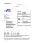
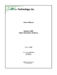
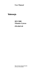
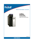
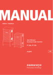
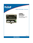
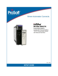
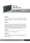
User's Manual
USB 2.0 Audio PCA
with 16 Bit I/O, 4 x 4 Audio Mixer
Part No: 10516
Document No: MAN10516
Revision: A
Date: 16SEP10
eMDee Technology, Inc.
www.emdee.com
eMDee Technology, Inc.
Document No: MAN10516
Table of Contents
1.0 Overview......................................................................................................................................................... 3
1.1 Block Diagram............................................................................................................................................ 3
1.2 Theory of Operation.................................................................................................................................... 4
1.2.1 USB Audio CODEC............................................................................................................................ 4
1.2.2 Microphone Pre-amplifiers.................................................................................................................. 4
1.2.3 Headphone/Speaker Amplifiers.......................................................................................................... 5
1.2.4 Audio Mixer......................................................................................................................................... 5
1.2.5 General-Purpose I/O (GPIO).............................................................................................................. 6
2.0 Hardware Configuration.................................................................................................................................. 7
2.1 Jumper Configurations................................................................................................................................ 7
2.1.1 Ground Connections (J1) Jumper Description....................................................................................8
2.1.2 Mic Bias Power (J7) Jumper Description............................................................................................ 8
2.1.3 Board Power (J8) Jumper Description................................................................................................ 8
2.1.4 Input Gain (J10, J13, J17, J22) Jumper Description...........................................................................9
2.1.5 Output Gain (J12, J18, J19, J20) Jumper Description........................................................................9
2.2 External Connectors................................................................................................................................. 10
2.2.1 J9, J14, J15, J16 Pinout................................................................................................................... 10
2.2.2 J5 Pinout........................................................................................................................................... 10
2.2.3 J11 Pinout......................................................................................................................................... 11
2.2.4 J21 Pinout......................................................................................................................................... 11
3.0 Software Drivers........................................................................................................................................... 12
3.1 Windows Audio Drivers............................................................................................................................. 12
3.2 Driver Installation...................................................................................................................................... 12
4.0 Software Interface......................................................................................................................................... 13
4.1 UsbI2COpen............................................................................................................................................. 13
4.2 UsbI2CClose............................................................................................................................................. 14
4.3 UsbI2CWrite............................................................................................................................................. 15
4.4 UsbI2CRead............................................................................................................................................. 18
4.5 UsbInputLevel........................................................................................................................................... 19
4.6 UsbOutputLevel........................................................................................................................................ 20
4.7 UsbOutputBalance.................................................................................................................................... 21
4.8 UsbGetInputLevel..................................................................................................................................... 22
4.9 UsbGetOutputLevel.................................................................................................................................. 23
4.10 UsbGetOutputBalance............................................................................................................................ 24
4.11 UsbGetBoardSchema............................................................................................................................. 25
5.0 Initialization Procedure.................................................................................................................................. 26
User's Manual, USB 2.0 Audio PCA with 16 Bit I/O, 4 x 4 Audio Mixer
Page 2 of 26
eMDee Technology, Inc.
Document No: MAN10516
1.0 OVERVIEW
This document describes the characteristics, configuration, and operation of eMDee Technology part number
10516: USB 2.0 Audio PCA with 16 Bit I/O and 4 x 4 Mixer. Sections 1 and 2 of this document describe the
hardware and its configuration. Sections 3, 4, and 5 describe the software drivers, API functions, and basic
initialization.
1.1 Block Diagram
Figure 1.1 shows a basic block diagram of the circuit board functionality. The main components of the board are
the USB audio CODEC, microphone pre-amplifiers, headphone/speaker amplifiers, mixer, and general-purpose
I/O (GPIO).
Figure 1.1: Block Diagram
User's Manual, USB 2.0 Audio PCA with 16 Bit I/O, 4 x 4 Audio Mixer
Page 3 of 26
eMDee Technology, Inc.
Document No: MAN10516
1.2 Theory of Operation
1.2.1 USB Audio CODEC
The main component of the circuit board is the Micronas UAC3576B CODEC. This CODEC provides a USB
interface, stereo audio input/ouptut, and an I 2C interface. The CODEC is compatible with the default Windows
audio drivers and appears as a USB sound device when connected to a Windows PC (Windows XP with Service
Pack 2 or higher is recommended).
1.2.2 Microphone Pre-amplifiers
The board has the capability to connect up to four microphones as independent audio inputs. The board's preamplifiers are compatible with dynamic microphones and electret-style microphones. When using electret-style
microphones, a bias voltage can be configured to power the microphone elements. Figure 1.2 shows a
simplified block diagram of one of the microphone pre-amplifiers on the board.
Figure 1.2: Microphone Input Block Diagram
When using a dynamic microphone, you connect the two wires from the microphone to the first stage of the preamplifier. This first stage has differential inputs and has a gain of +40dB. The connection between the first and
second stages of the pre-amplifier is not connected by default, so you will need to place a jumper between the
two stages when using a dynamic microphone (see Section 2.2.3 for connector pinouts).
When using an electret-style microphone, you connect the signal wire from the microphone to the second stage
of the pre-amplifier and the ground wire to analog ground. In this case, it is not necessary to physically connect
the first and second amplifier stages. If the microphone requires a bias voltage, there are several ways to
connect this voltage to the microphone signal line. Refer to Section 2.1.2 for details on configuring a bias
voltage.
The second stage of the pre-amplifier is a variable gain amplifier that is jumper-selectable from 0dB to +36dB.
Refer to Section 2.1.4 for details on setting the gain jumpers for the second amplifier stage.
Also provided in the microphone pre-amplifier is a push-to-talk (PTT) detection circuit for certain types of
microphones. The proper operation of this circuit will require an electret-style microphone that uses a bias
voltage to power the mic element – the PTT detection circuit will not work with any other type of microphone.
The PTT detection circuit monitors the voltage on the microphone signal line and generates a signal to the GPIO
when the bias voltage drops below a certain level (indicating that the microphone has been activated). In order
to read the PTT in this manner, you will also need to place jumpers (see Sec. 2.2.2 ) to route the signal from the
PTT detection circuit to the GPIO.
User's Manual, USB 2.0 Audio PCA with 16 Bit I/O, 4 x 4 Audio Mixer
Page 4 of 26
eMDee Technology, Inc.
Document No: MAN10516
1.2.3 Headphone/Speaker Amplifiers
The board has the capability to connect up to four headphones or speakers as independent audio outputs. Each
output has a power amplifier that is capable of producing up to 1.2W into an 8 ohm load. Figure 1.3 shows a
simplified block diagram of one of the output amplifiers on the board.
Figure 1.3: Headphone/Speaker Output Block Diagram
The output of the mixer is routed to a three pin connector that can be used for external volume control of the
output audio signal. Typically, a potentiometer is connected to the three pins to provide a voltage divider into the
input of the amplifier to vary the output signal. If no volume control is needed, you may also insert a jumper
between pins 1 and 2 of the connector to connect the full-scale signal to the amplifier. Refer to Section 2.2.1
for details on these connectors.
The output amplifier is also gain adjustable from 0 to +16dB. Refer to Section 2.1.5 for details on configuration
of the output amplifier gain jumpers.
The output of the amplifier can be connected to a headphone or speaker. The headphone is connected between
one half of the amplifier and ground while the speaker is connected to two bridged amplifiers to provide more
output power. Refer to Section 2.2.4 for details on connecting headphones and/or speakers to the board.
1.2.4 Audio Mixer
There is a 6 input/6 output mixer on the board that routes all of the audio to/from the inputs, outputs, and the
CODEC. This is a simple mixer and contains only on/off controls for inputs to outputs and does not provide for
individual volume control of the various mixer paths. It does, however, mix the audio signals together so that
more than one audio signal can be combined into an output.
The 6 inputs to the mixer are the 4 microphone inputs plus the left and right outputs of the CODEC. Note that
the outputs of the CODEC are connected to the inputs of the mixer. This enables audio that is played from the
CODEC to be sent to any of the mixer outputs.
The 6 outputs from the mixer are the 4 headphone/speaker outputs plus the left and right inputs of the CODEC.
Note that the outputs of the mixer are connected to the inputs of the CODEC. This enables audio from any of
the microphones to be sent to the CODEC.
The mixer is controlled through a software interface that enables/disables the various paths that connect inputs
to outputs within the mixer. Section 4.3 details a map of the controls that are available in the mixer and how to
call the API function to enable/disable the controls.
User's Manual, USB 2.0 Audio PCA with 16 Bit I/O, 4 x 4 Audio Mixer
Page 5 of 26
eMDee Technology, Inc.
Document No: MAN10516
1.2.5 General-Purpose I/O (GPIO)
A bank of discrete I/O pins are available on the board so that external devices can be connected to the board
such as an external PTT switch or selection switch. There are 16 GPIO bits, of which 12 can be used for
general-purpose and 4 are reserved for controlling the shutdown function for each of the output amplifiers. The
GPIO pins are configurable as inputs or outputs and each bit can be configured separately as an input or an
output.
Refer to Section 2.2.2 for details on connecting components to the GPIO pins. Also refer to Section 4.3 for
details on the software control of the GPIO.
User's Manual, USB 2.0 Audio PCA with 16 Bit I/O, 4 x 4 Audio Mixer
Page 6 of 26
eMDee Technology, Inc.
Document No: MAN10516
2.0 HARDWARE CONFIGURATION
This section describes how to configure the hardware for the various functions of the board and details the
connectors that are available to external components. Figure 2.1 shows the physical layout of the circuit board
identifying the jumper locations and external connector locations.
Figure 2.1: Jumper and Connector Locations
2.1 Jumper Configurations
Jumper
Function
J1
Ground Connections (see Sec. 2.1.1 )
J7
Mic Bias Power (see Sec. 2.1.2 )
J8
Board Power (see Sec. 2.1.3 )
J10
Input 1 Gain (see Sec. 2.1.4 )
J13
Input 2 Gain (see Sec. 2.1.4 )
J17
Input 3 Gain (see Sec. 2.1.4 )
J22
Input 4 Gain (see Sec. 2.1.4 )
J12
Output 1 Gain (see Sec. 2.1.5 )
J18
Output 2 Gain (see Sec. 2.1.5 )
J19
Output 3 Gain (see Sec. 2.1.5 )
J20
Output 4 Gain (see Sec. 2.1.5 )
User's Manual, USB 2.0 Audio PCA with 16 Bit I/O, 4 x 4 Audio Mixer
Page 7 of 26
eMDee Technology, Inc.
Document No: MAN10516
2.1.1 Ground Connections (J1) Jumper Description
Jumper J1 provides the ability to connect the circuit board ground planes. The three ground planes are:
•
Chassis Ground – USB connector shell and mounting screws
•
Analog Ground – Ground reference for all audio amplifiers and mixers
•
Digital Ground – Ground reference for USB CODEC and digital I/O
The following table shows the jumper pins with a description of each pin:
Chassis Ground
1
2
Digital Ground
Analog Ground
3
4
Digital Ground
not used
5
6
not used
2.1.2 Mic Bias Power (J7) Jumper Description
Jumper J7 (along with connector J6) provides the ability to configure the power source for the microphone bias
voltage that can be used to power electret-style microphones. The following table shows the jumper pins with a
description of each pin:
Mic Bias
1
2
Analog +5VDC
Analog Ground
3
4
n/c
This jumper/connector allows for several different modes of power the mic bias:
•
Leave all pins of J7 unconnected (open) and connect an external 12VDC power supply to J6 (in this
mode, DO NOT jumper any of the J7 pins)
•
Connect an external 12VDC power supply to pins 1 and 3 of J7 (in this mode, DO NOT connect anything
to J6)
•
Place a jumper between pins 1 and 2 to connect board power (+5VDC) to the mic bias (in this mode, DO
NOT connect anything to J6)
•
If no microphone bias voltage is needed, do not jumper or connect anything to J6 or J7.
2.1.3 Board Power (J8) Jumper Description
Jumper J8 provides the ability to configure the main source of power for the circuit board. The following table
shows the jumper pins with a description of each pin:
USB Power (+5VDC)
1
2
Board Power
Digital Ground
3
4
Board Power
User's Manual, USB 2.0 Audio PCA with 16 Bit I/O, 4 x 4 Audio Mixer
Page 8 of 26
eMDee Technology, Inc.
Document No: MAN10516
This jumper/connector allows for two different modes of powering the circuit board:
•
Place a jumper between pins 1 and 2 to power the board from the USB bus power (in this mode, DO
NOT connect a jumper between pins 3 & 4)
•
Connect an external +5VDC power supply to pins 3 and 4 (in this mode, DO NOT connect a jumper
between pins 1 and 2).
2.1.4 Input Gain (J10, J13, J17, J22) Jumper Description
The input gain jumpers (J10, J13, J17, J22) set the gain of the second amplifier stage (refer to Fig. 1.2.2) of the
microphone inputs. The gain can be set from 0dB to +36dB in +12dB increments. The following table shows the
jumper settings for the valid gain settings of the input amplifier:
Jumper Location
Gain
0dB
+12dB
+24dB
+36dB
2.1.5 Output Gain (J12, J18, J19, J20) Jumper Description
The output gain jumpers (J12, J18, J19, J20) set the gain of the output power amplifiers (refer to Fig. 1.3). The
gain can be set from 0dB to +16dB. The following table shows the jumper settings for the valid gain settings of
the output amplifier:
Jumper Location
Gain
0dB
+11dB
+16dB
User's Manual, USB 2.0 Audio PCA with 16 Bit I/O, 4 x 4 Audio Mixer
Page 9 of 26
eMDee Technology, Inc.
Document No: MAN10516
2.2 External Connectors
2.2.1 J9, J14, J15, J16 Pinout
The connectors J9, J14, J15, and J16 are provided for connection of a potentiometer to create a voltage divider
between the mixer output and amplifier input so that the output signal can be varied with an external control.
The potentiometer should be connected so that the wiper is connected to pin 2 and the ends of the
potentiometer are connected to pins 1 and 3 so that when the potentiometer is turned completely clockwise, the
resistance between pin 1 and 2 will be 0 ohms.
If no external volume control is needed, you can simply insert a jumper between pins 1 and 2 to connect the full
signal to the output amplifier.
Mixer Output
1
Amplifier Input
2
Analog Ground
3
2.2.2 J5 Pinout
GPIO Bit 0
1
2
GPIO Bit 1
GPIO Bit 2
3
4
GPIO Bit 3
Digital Ground
5
6
Digital Ground
GPIO Bit 4
7
8
GPIO Bit 5
GPIO Bit 6
9
10
GPIO Bit 7
Digital Ground
11
12
Digital Ground
PTT 1 Detect
13
14
GPIO Bit 8
PTT 2 Detect
15
16
GPIO Bit 9
Digital Ground
17
18
Digital Ground
PTT 3 Detect
19
20
GPIO Bit 10
PTT 4 Detect
21
22
GPIO Bit 11
Digital Ground
23
24
Digital Ground
User's Manual, USB 2.0 Audio PCA with 16 Bit I/O, 4 x 4 Audio Mixer
Page 10 of 26
eMDee Technology, Inc.
Document No: MAN10516
2.2.3 J11 Pinout
Dynamic Mic 1 Input
1
2
Electret Mic 1 Input
Dynamic Mic 1 Input (+)
3
4
Analog Ground
Dynamic Mic 1 Input (-)
5
6
Analog Ground
Dynamic Mic 2 Input
7
8
Electret Mic 2 Input
Dynamic Mic 2 Input (+)
9
10
Analog Ground
Dynamic Mic 2 Input (-)
11
12
Analog Ground
Dynamic Mic 3 Input
13
14
Electret Mic 3 Input
Dynamic Mic 3 Input (+)
15
16
Analog Ground
Dynamic Mic 3 Input (-)
17
18
Analog Ground
Dynamic Mic 4 Input
19
20
Electret Mic 4 Input
Dynamic Mic 4 Input (+)
21
22
Analog Ground
Dynamic Mic 4 Input (-)
23
24
Analog Ground
Headphone 1 Output (+)
1
2
Speaker 1 Output (+)
Analog Ground
3
4
Speaker 1 Output (-)
Un-amplified 1 Output
5
6
Analog Ground
Headphone 2 Output (+)
7
8
Speaker 2 Output (+)
Analog Ground
9
10
Speaker 2 Output (-)
Un-amplified 2 Output
11
12
Analog Ground
Headphone 3 Output (+)
13
14
Speaker 3 Output (+)
Analog Ground
15
16
Speaker 3 Output (-)
Un-amplified 3 Output
17
18
Analog Ground
Headphone 4 Output (+)
19
20
Speaker 4 Output (+)
Analog Ground
21
22
Speaker 4 Output (-)
Un-amplified 4 Output
23
24
Analog Ground
2.2.4 J21 Pinout
User's Manual, USB 2.0 Audio PCA with 16 Bit I/O, 4 x 4 Audio Mixer
Page 11 of 26
eMDee Technology, Inc.
Document No: MAN10516
3.0 SOFTWARE DRIVERS
The following sections detail the procedures for installing the Windows multimedia drivers and the specialpurpose board drivers. These procedures should be followed before attempting to use the board.
3.1 Windows Audio Drivers
When the USB audio device is plugged in, Windows will automatically detect the USB CODEC and will load
default sound drivers for it.
3.2 Driver Installation
After the USB device has been plugged in and Windows has detected the presence of the audio device, you will
need to finish the installation of the special-purpose drivers to finish your installation. The drivers are provided
with your USB device. You will need to run INSTALL.EXE to start the automatic installation of the drivers.
Once the drivers have been installed, you will need to unplug the USB device, wait a few seconds, and the replug the device (or you can hold the reset button down for 2 to 3 seconds). This will reboot the device with the
newly installed drivers.
To verify the proper installation of the special-purpose drivers, open the Device Manager in Windows and verify
that a device named eMDee Composite USB-Device 0 is listed under Universal Serial Bus controllers.
To verify the proper installation of the audio drivers, open the Sounds and Audio Devices Properties Control
Panel window and verify that eMDee Audio 0 is available as one of the sound devices in your system.
To finalize the driver installation and setup, you will need to copy the file uac2.dll into your Windows System
folder. At this point the USB device is ready for communication. The following section details how to interface to
the USB device through your own customized software application.
User's Manual, USB 2.0 Audio PCA with 16 Bit I/O, 4 x 4 Audio Mixer
Page 12 of 26
eMDee Technology, Inc.
Document No: MAN10516
4.0 SOFTWARE INTERFACE
The following sections detail the software interface, or API, that is available for this board. All of these functions
are available in the dynamically linked library (DLL) named UsbI2C.dll. Prototypes for each function are
provided in a header file named UsbI2CInterface.h.
For proper operation, the USB device drivers must be loaded properly (see Section 3.1) and the files uacb.dll
and uac2.dll must be in the Windows system directory.
4.1 UsbI2COpen
UAC_HANDLE UsbI2cOpen(int devAddress);
Return Value
If successful, this function returns a handle to an open USB device that will be used as a reference in
subsequent function calls. If not successful, this function returns NULL.
Parameters
devAddress
Physical address of the USB device. The physical address of this board is always '0'.
Remarks
Use this function to open a USB device and retrieve a handle to it.
User's Manual, USB 2.0 Audio PCA with 16 Bit I/O, 4 x 4 Audio Mixer
Page 13 of 26
eMDee Technology, Inc.
Document No: MAN10516
4.2 UsbI2CClose
void UsbI2cClose(HANDLE devHandle);
Return Value
None.
Parameters
devHandle
Handle of an open USB device (retrieved from UsbI2COpen).
Remarks
Use this function to close the USB device and release the driver.
User's Manual, USB 2.0 Audio PCA with 16 Bit I/O, 4 x 4 Audio Mixer
Page 14 of 26
eMDee Technology, Inc.
Document No: MAN10516
4.3 UsbI2CWrite
int UsbI2cWrite(UAC_HANDLE devHandle, unsigned short address, char *data, unsigned short length);
Return Value
Macro
Value
Description
UACI2C_OK
0
Successful
UACI2C_NOT_CONNECTED
1
Device not connected
UACI2C_GENERAL_ERROR
2
Undefined/Generic error
UACI2C_BUSY
3
Device is busy
UACI2C_TIMEOUT
4
Device timed out
UACI2C_NO_ACK
5
No response from device
UACI2C_NO_DATA
6
No data from device
Parameters
devHandle
Handle of an open USB device (retrieved from UsbI2COpen).
address
Address of the I/O bank to write to. Each I/O bank contains two 8-bit bytes. Refer to the Remarks
section for details of the valid I/O banks for this board.
data
A pointer to two 8-bit bytes of data that will be written to the I/O bank.
length
The number of bytes that are allocated in the data array (for this board, the value should always be 2).
Remarks
Use this function to write to the general-purpose I/O (GPIO) and mixer control. The I/O arrangement for this
board is 3 I/O banks, each with 16 bits. The table below shows the assignment of each bit within the I/O banks:
Address
Byte
Bit
Function
20h
0
0
GPIO Bit 0 (J5, pin 1)
1
GPIO Bit 1 (J5, pin 2)
2
GPIO Bit 2 (J5, pin 3)
User's Manual, USB 2.0 Audio PCA with 16 Bit I/O, 4 x 4 Audio Mixer
Page 15 of 26
eMDee Technology, Inc.
Address
Document No: MAN10516
Byte
1
21h
0
1
22h
0
Bit
Function
3
GPIO Bit 3 (J5, pin 4)
4
GPIO Bit 4 (J5, pin 7)
5
GPIO Bit 5 (J5, pin 8)
6
GPIO Bit 6 (J5, pin 9)
7
GPIO Bit 7 (J5, pin 10)
0
GPIO Bit 8 (J5, pin 14)
1
GPIO Bit 9 (J5, pin 16)
2
GPIO Bit 10 (J5, pin 20)
3
GPIO Bit 11 (J5, pin 22)
4
Channel 1 Output Amplifier Shutdown
5
Channel 2 Output Amplifier Shutdown
6
Channel 3 Output Amplifier Shutdown
7
Channel 4 Output Amplifier Shutdown
0
Mixer Control - Input 1 to Output 1
1
Mixer Control - Input 2 to Output 1
2
Mixer Control - Input 3 to Output 1
3
Mixer Control - Input 4 to Output 1
4
Mixer Control - Input 1 to Output 2
5
Mixer Control - Input 2 to Output 2
6
Mixer Control - Input 3 to Output 2
7
Mixer Control - Input 4 to Output 2
0
Mixer Control - Input 1 to Output 3
1
Mixer Control - Input 2 to Output 3
2
Mixer Control - Input 3 to Output 3
3
Mixer Control - Input 4 to Output 3
4
Mixer Control - Input 1 to Output 4
5
Mixer Control - Input 2 to Output 4
6
Mixer Control - Input 3 to Output 4
7
Mixer Control - Input 4 to Output 4
0
Mixer Control – CODEC Left Output to Output 1
1
Mixer Control – CODEC Right Output to Output 1
2
Mixer Control – CODEC Left Output to Output 2
3
Mixer Control – CODEC Right Output to Output 2
4
Mixer Control – CODEC Left Output to Output 3
User's Manual, USB 2.0 Audio PCA with 16 Bit I/O, 4 x 4 Audio Mixer
Page 16 of 26
eMDee Technology, Inc.
Address
Document No: MAN10516
Byte
1
Bit
Function
5
Mixer Control – CODEC Right Output to Output 3
6
Mixer Control – CODEC Left Output to Output 4
7
Mixer Control – CODEC Right Output to Output 4
0
Mixer Control – Input 1 to CODEC Left Input
1
Mixer Control – Input 2 to CODEC Left Input
2
Mixer Control – Input 3 to CODEC Left Input
3
Mixer Control – Input 4 to CODEC Left Input
4
Mixer Control – Input 1 to CODEC Right Input
5
Mixer Control – Input 2 to CODEC Right Input
6
Mixer Control – Input 3 to CODEC Right Input
7
Mixer Control – Input 4 to CODEC Right Input
User's Manual, USB 2.0 Audio PCA with 16 Bit I/O, 4 x 4 Audio Mixer
Page 17 of 26
eMDee Technology, Inc.
Document No: MAN10516
4.4 UsbI2CRead
int UsbI2cRead(UAC_HANDLE devHandle, unsigned short address, char *data, unsigned short length);
Return Value
Macro
Value
Description
UACI2C_OK
0
Successful
UACI2C_NOT_CONNECTED
1
Device not connected
UACI2C_GENERAL_ERROR
2
Undefined/Generic error
UACI2C_BUSY
3
Device is busy
UACI2C_TIMEOUT
4
Device timed out
UACI2C_NO_ACK
5
No response from device
UACI2C_NO_DATA
6
No data from device
Parameters
devHandle
Handle of an open USB device (retrieved from UsbI2COpen).
address
Address of the I/O bank to write to. Each I/O bank contains two 8-bit bytes. Refer to the Remarks
section for details of the valid I/O banks for this board.
data
A pointer to two 8-bit bytes of data that will receive the data from the I/O bank.
length
The number of bytes that are allocated in the data array (for this board, the value should always be 2).
Remarks
Use this function to read from the general-purpose I/O (GPIO). On this board, there are 12 bits of GPIO. Each
of these bits can be configured as either input (read) or output (write). To configure a bit as an input, you must
first write a '1' to that bit to enable it as an input bit. These bits will be latched in, there is no need to re-write the
bits before each read.
For example, to configure GPIO bits 0, 3, 6, and 9 as inputs, use UsbI2CWrite to send 49h (0100 1001b) and
02h (0000 0010b) to the I/O bank at address 20h. Then perform a UsbI2CRead to read from the same I/O bank
to get the value of the bits configured as input. Since the inputs are active low, an input that is connected to
ground will read back as a '0' on that bit.
Note that bits 4 – 7 of byte 1 are reserved for shutdown control of the amplifiers. These bits must always be
written as '0' when configuring the GPIO. A '1' written to these bits will put the amplifier in “shutdown” mode.
User's Manual, USB 2.0 Audio PCA with 16 Bit I/O, 4 x 4 Audio Mixer
Page 18 of 26
eMDee Technology, Inc.
Document No: MAN10516
4.5 UsbInputLevel
int UsbInputLevel(UAC_HANDLE devHandle, float level, int leftOrRight);
Return Value
Macro
Value
Description
UACI2C_OK
0
Successful
UACI2C_NOT_CONNECTED
1
Device not connected
UACI2C_GENERAL_ERROR
2
Undefined/Generic error
UACI2C_BUSY
3
Device is busy
UACI2C_TIMEOUT
4
Device timed out
UACI2C_NO_ACK
5
No response from device
UACI2C_NO_DATA
6
No data from device
Parameters
devHandle
Handle of an open USB device (retrieved from UsbI2COpen).
level
A normalized value from 0.0 to 1.0 that represents the volume level of the input. A value of 0.0 will be
minimum volume and a value of 1.0 will be maximum volume.
leftOrRight
Writes level to the left or right channel based on the following values:
0 = Left CODEC channel
1 = Right CODEC channel
Remarks
Use this function to set the input volume level of the audio CODEC. This function can be used to control the
overall level of the audio signals that will be captured by the CODEC.
User's Manual, USB 2.0 Audio PCA with 16 Bit I/O, 4 x 4 Audio Mixer
Page 19 of 26
eMDee Technology, Inc.
Document No: MAN10516
4.6 UsbOutputLevel
int UsbOutputLevel(UAC_HANDLE devHandle, float level);
Return Value
Macro
Value
Description
UACI2C_OK
0
Successful
UACI2C_NOT_CONNECTED
1
Device not connected
UACI2C_GENERAL_ERROR
2
Undefined/Generic error
UACI2C_BUSY
3
Device is busy
UACI2C_TIMEOUT
4
Device timed out
UACI2C_NO_ACK
5
No response from device
UACI2C_NO_DATA
6
No data from device
Parameters
devHandle
Handle of an open USB device (retrieved from UsbI2COpen).
level
A normalized value from 0.0 to 1.0 that represents the volume level of the output. A value of 0.0 will be
minimum volume and a value of 1.0 will be maximum volume.
Remarks
Use this function to set the output volume level of the audio CODEC. This is the overall volume level of both
channels of the CODEC. This function, in combination with UsbOutputBalance can be used to set the level of
the left and right output channels of the CODEC.
User's Manual, USB 2.0 Audio PCA with 16 Bit I/O, 4 x 4 Audio Mixer
Page 20 of 26
eMDee Technology, Inc.
Document No: MAN10516
4.7 UsbOutputBalance
int UsbOutputBalance(UAC_HANDLE devHandle, float fPan);
Return Value
Macro
Value
Description
UACI2C_OK
0
Successful
UACI2C_NOT_CONNECTED
1
Device not connected
UACI2C_GENERAL_ERROR
2
Undefined/Generic error
UACI2C_BUSY
3
Device is busy
UACI2C_TIMEOUT
4
Device timed out
UACI2C_NO_ACK
5
No response from device
UACI2C_NO_DATA
6
No data from device
Parameters
devHandle
Handle of an open USB device (retrieved from UsbI2COpen).
fPan
A normalized value from -1.0 to 1.0 representing the balance, or pan, of the output. A value of -1.0 will
pan the output completely to the left channel and a value of 1.0 will pan the output completely to the right
channel. The value is continuous between -1.0 and 1.0 with a value of 0.0 being the center (equal
volume to both left and right channels).
Remarks
Use this function to set the output balance of the audio CODEC. This is the “pan position” for the audio signals
being sent from the audio CODEC. This function, in combination with UsbOutputLevel can be used to set the
level of the left and right output channels of the CODEC.
User's Manual, USB 2.0 Audio PCA with 16 Bit I/O, 4 x 4 Audio Mixer
Page 21 of 26
eMDee Technology, Inc.
Document No: MAN10516
4.8 UsbGetInputLevel
float UsbGetInputLevel(UAC_HANDLE devHandle, int leftOrRight);
Return Value
The input level that is currently set for the audio CODEC.
Parameters
devHandle
Handle of an open USB device (retrieved from UsbI2COpen).
leftOrRight
Reads the input level from the left or right channel based on the following values:
0 = Left CODEC channel
1 = Right CODEC channel
Remarks
Use this function to retrieve the input volume level of the audio CODEC. This function can be used to read the
default levels of the CODEC after initialization, or to verify the value written from a call to UsbInputLevel.
User's Manual, USB 2.0 Audio PCA with 16 Bit I/O, 4 x 4 Audio Mixer
Page 22 of 26
eMDee Technology, Inc.
Document No: MAN10516
4.9 UsbGetOutputLevel
float UsbGetOutputLevel(UAC_HANDLE devHandle);
Return Value
The output level that is currently set for the audio CODEC.
Parameters
devHandle
Handle of an open USB device (retrieved from UsbI2COpen).
Remarks
Use this function to retrieve the output volume level of the audio CODEC. This function can be used to read the
default level of the CODEC after initialization, or to verify the value written from a call to UsbOutputLevel.
User's Manual, USB 2.0 Audio PCA with 16 Bit I/O, 4 x 4 Audio Mixer
Page 23 of 26
eMDee Technology, Inc.
Document No: MAN10516
4.10 UsbGetOutputBalance
float UsbGetOutputBalance(UAC_HANDLE devHandle);
Return Value
The output balance that is currently set for the audio CODEC.
Parameters
devHandle
Handle of an open USB device (retrieved from UsbI2COpen).
Remarks
Use this function to retrieve the output balance of the audio CODEC. This function can be used to read the
default value of the CODEC after initialization, or to verify the value written from a call to UsbOutputBalance.
User's Manual, USB 2.0 Audio PCA with 16 Bit I/O, 4 x 4 Audio Mixer
Page 24 of 26
eMDee Technology, Inc.
Document No: MAN10516
4.11 UsbGetBoardSchema
int UsbGetBoardSchema(UAC_HANDLE devHandle);
Return Value
The value of the board schema (see Remarks).
Parameters
devHandle
Handle of an open USB device (retrieved from UsbI2COpen).
Remarks
Use this function to retrieve the schema value of the circuit board hardware. This value is hard-wired as '1' and
represents the current (and only) revision level of the hardware. This function is provided so that the same
software can be used for different versions of hardware.
User's Manual, USB 2.0 Audio PCA with 16 Bit I/O, 4 x 4 Audio Mixer
Page 25 of 26
eMDee Technology, Inc.
Document No: MAN10516
5.0 INITIALIZATION PROCEDURE
To initialize the board and get it ready for use:
1. Call UsbI2COpen and save the returned value as the handle to the open device
2. (optional) Call UsbGetInputLevel to retrieve the CODEC left and right channel input volume settings
3. (optional) Call UsbGetOutputLevel and UsbGetOutputBalance to retrieve the CODEC output volume
and pan settings
4. Call UsbI2CWrite to address 0x20 with bytes FFh and 0Fh. This will enable the four output amplifiers
and configure GPIO bits 0 through 12 as inputs (refer to the UsbI2CRead documentation in section 4.4
for details on configuring the GPIO bits as outputs).
The board is now ready for general use. You can record from and playback to the CODEC device just as you
would any standard Windows audio device. Refer to the UsbI2CWrite documentation in section 4.3 for details
on how to route and mix the CODEC audio to the outputs and the audio inputs to the CODEC.
Before exiting your application, call UsbClose with the handle to the open device to release the driver.
User's Manual, USB 2.0 Audio PCA with 16 Bit I/O, 4 x 4 Audio Mixer
Page 26 of 26