1
Gill Instruments Ltd
_____________________________________________________________________________________________________________
4. PRE-INSTALLATION
4.1.
and
and
and
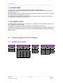
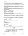
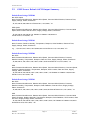
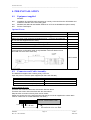
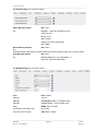
Equipment supplied
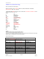
MaxiMet
Installation kit (1405-PK-069) comprising of a 9 way connector kit and 3 off M5 bolts and
washers to bolt the unit to a mounting pole.
MaxiMet User Manual and MetSet Software on a CD in the MaxiMet box (this manual).
Product Test Report.
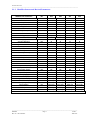
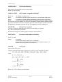
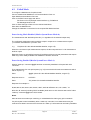
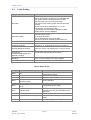
Optional Extras:
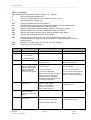
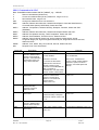
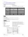
Item
Cable 3 Pair twisted and Shielded wires, 24awg, per metre.
Part Number
026-02660
Cable 4 Pair twisted and Shielded wires, 24awg, per metre.
Cable 15 metres (4 pair twisted and shielded 24 awg – connector pins attached
to one end and stripped wires the other).
9 way connector and 3 mounting bolts (1 supplied with the unit)
0.5 Metre x 50mm Aluminium Support Tube tapped for MaxiMet Mounting bolts
026-03156
50cm Lanyard
MaxiMet 1.8 Metre RS232 to USB converter including 5v dc power and
communication configuration cable (9 way MaxiMet connector fitted one end
and USB connector at the other end).
1405-10-080
1405-PK-069
1405-30-056
026-05335
1957-10-065
4.2.
Connector and Cable Assembly.
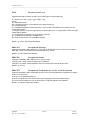
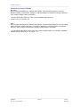
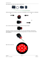
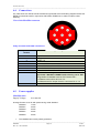
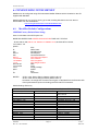
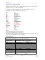
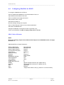
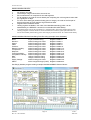
The MaxiMet is supplied with a mating 9 way connector.
Open the pack of connector parts supplied (Gill Part 1405-PK-069).
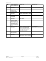
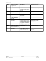
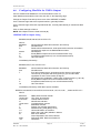
Part Name
Souriau Clipper Part Number.
Connector 9 way
CLF1201
Backshell
CL101021
Solder bucket contacts (9 required)
CM10SS10MQ
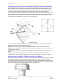
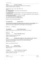
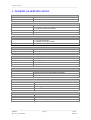
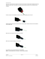
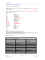
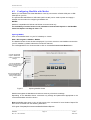
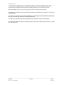
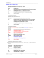
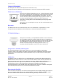
Arrange Backshell Parts.
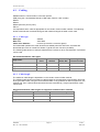
Trim back the screened cable outer and screen sleeves 40mm.
Trim back the screen drain wires flush with the outer sleeve.
Strip back the connection wires by 5mm and tin solder.
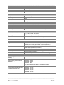
Solder the contact pins to the wires (please note that the connector supplies the correct strain
relief for cables with an outside diameter of 6-12mm).
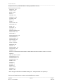
Screen Twisted Pair Cable
5 mm
40 mm
Screen drain wires cut flush
________________________________________________________________________________________________
MaxiMet
Page 18
Issue 2
Doc. No. 1957-PS-000x
June 2015