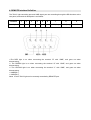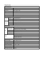
1
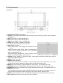
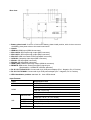
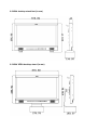
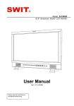
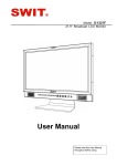
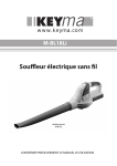
·Rear view
⑴ Battery plate Install: V-mount or Gold mount battery plates install position, with a hole to connect
the battery plate power wires to the main board inside.
⑵ Handle
⑶ HDMI-IN: HDMI input (HDMI-A connector)
⑷ SDI-LOOP2: SDI loop through output (BNC connector)
⑸ SDI-LOOP1: SDI loop through output (BNC connector)
⑹ SDI-OUT: HDMI converted to SDI output(BNC connector)
⑺ CVBS-IN: Composite video input (BNC connector)
⑻ SDI-IN1: SDI input (BNC connector)
⑼ SDI-IN2: SDI input (BNC connector)
⑽ HDMI-LOOP: HDMI loop through output (HDMI-A connector)
⑾ REMOTE: DB9 socket, external controlling signal input.
(See details in “4.REMOTE interface definition”)
⑿ DC IN 11V-17V BACK UP: Connect with 4-pin XLR power adaptor (Pin 1: Negative, Pin 4: Positive)
⒀ DC IN 11V-17V MAIN: Connect with 4-pin XLR power adaptor (Pin 1: Negative, Pin 4: Positive)
⒁ VESA installation position: standard 10×10cm VESA thread
·Input Formats
Input
Supported formats
CVBS
PAL / NTSC
480I / 576I / 480P / 576P
1080i (60 / 59.94 / 50)
HDMI
720p (60 / 59.94 / 50)
1080p (60 / 59.94 / 50 / 30 / 29.97 / 25 / 24 / 23.98)
SMPTE-274M
SDI
1080i (60 / 59.94 / 50)
1080p (30 / 29.97 / 25 / 24 / 23.98)
SMPTE-RP211
1080psf (30 / 29.97 / 25 / 24 / 23.98)
SMPTE-296M
720p (60 / 59.94 / 50)
SMPTE-125M
480i (59.94)
ITU-R BT.656
576i (50)