1
Hart Scientific
5944/5945/5946/5947
Mini Metal Fixed Point Cells
User’s Guide
Rev. 6C0601
Limited Warranty & Limitation of Liability
Each product from Fluke Corporation, Hart Scientific Division ("Hart") is warranted to be free from defects in material and workmanship under normal use and service. The warranty period is one year for the
Mini Metal Fixed Point Cell. The warranty period begins on the date of the shipment. Parts, product repairs, and services are warranted for 90 days. The warranty extends only to the original buyer or end-user
customer of a Hart authorized reseller, and does not apply to fuses, disposable batteries or to any other
product, which in Hart's opinion, has been misused, altered, neglected, or damaged by accident or abnormal conditions of operation or handling. Hart warrants that software will operate substantially in accordance with its functional specifications for 90 days and that it has been properly recorded on
non-defective media. Hart does not warrant that software will be error free or operate without interruption. Hart does not warrant calibrations on the Mini Metal Fixed Point Cell.
Hart authorized resellers shall extend this warranty on new and unused products to end-user customers
only but have no authority to extend a greater or different warranty on behalf of Hart. Warranty support is
available if product is purchased through a Hart authorized sales outlet or Buyer has paid the applicable
international price. Hart reserves the right to invoice Buyer for importation costs of repairs/replacement
parts when product purchased in one country is submitted for repair in another country.
Hart's warranty obligation is limited, at Hart's option, to refund of the purchase price, free of charge repair, or replacement of a defective product which is returned to a Hart authorized service center within
the warranty period.
To obtain warranty service, contact your nearest Hart authorized service center or send the product, with
a description of the difficulty, postage, and insurance prepaid (FOB Destination), to the nearest Hart authorized service center. Hart assumes no risk for damage in transit. Following warranty repair, the product will be returned to Buyer, transportation prepaid (FOB Destination). If Hart determines that the
failure was caused by misuse, alteration, accident or abnormal condition or operation or handling, Hart
will provide an estimate or repair costs and obtain authorization before commencing the work. Following
repair, the product will be returned to the Buyer transportation prepaid and the Buyer will be billed for
the repair and return transportation charges (FOB Shipping Point).
THIS WARRANTY IS BUYER'S SOLE AND EXCLUSIVE REMEDY AND IS IN LIEU OF ALL
OTHER WARRANTIES, EXPRESS OR IMPLIED, INCLUDING BUT NOT LIMITED TO ANY IMPLIED WARRANTY OF MERCHANTABILITY OR FITNESS FOR A PARTICULAR PURPOSE.
HART SHALL NOT BE LIABLE FOR ANY SPECIAL, INDIRECT, INCIDENTAL. OR CONSEQUENTIAL DAMAGES OR LOSSES, INCLUDING LOSS OF DATA, WHETHER ARISING FROM
BREACH OF WARRANTY OR BASED ON CONTRACT, TORT, RELIANCE OR ANY OTHER
THEORY.
Since some countries or states do not allow limitation of the term of an implied warranty, or exclusion or
limitation of incidental or consequential damages, the limitations and exclusions of this warranty may not
apply to every buyer. If any provision of this Warranty is held invalid or unenforceable by a court of competent jurisdiction, such holding will not affect the validity or enforceability of any other provision.
Fluke Corporation, Hart Scientific Division
799 E. Utah Valley Drive • American Fork, UT 84003-9775 • USA
Phone: +1.801.763.1600 • Telefax: +1.801.763.1010
E-mail: [email protected]
www.hartscientific.com
Subject to change without notice. • Copyright © 2005 • Printed in USA
Rev. 6C0601
Table of Contents
1 Before You Start . . . . . . . . . . . . . . . . . . . . . . . . . . 1
1.1
1.2
Symbols Used . . . . . . . . . . . . . . . . . . . . . . . . . . . . 1
Safety Information . . . . . . . . . . . . . . . . . . . . . . . . . . 2
1.2.1
1.2.2
1.3
Warnings . . . . . . . . . . . . . . . . . . . . . . . . . . . . . . . . . . . . . 2
Cautions . . . . . . . . . . . . . . . . . . . . . . . . . . . . . . . . . . . . . 2
Authorized Service Centers. . . . . . . . . . . . . . . . . . . . . . 3
2 Introduction . . . . . . . . . . . . . . . . . . . . . . . . . . . . 5
3 Specifications and Environmental Conditions . . . . . . . . . . 7
3.1
3.2
Specifications . . . . . . . . . . . . . . . . . . . . . . . . . . . . . 7
Environmental Conditions . . . . . . . . . . . . . . . . . . . . . . 7
4 Construction . . . . . . . . . . . . . . . . . . . . . . . . . . . . 9
5 Care and Handling Guidelines . . . . . . . . . . . . . . . . . 11
6 Realization of the Fixed Point . . . . . . . . . . . . . . . . . . 13
6.1
6.2
Background Information . . . . . . . . . . . . . . . . . . . . . . 13
Vertical Temperature Gradient and Controller Accuracy Adjustment
20
6.2.1
6.2.2
Vertical temperature gradient adjustment. . . . . . . . . . . . . . . . . . . . 20
Controller display accuracy adjustment. . . . . . . . . . . . . . . . . . . . . 21
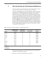
6.3
Procedure for Realizing the Freeze . . . . . . . . . . . . . . . . . 21
6.4
6.5
Procedure for Realizing the Melting Point . . . . . . . . . . . . . 22
Special notes for freezing point of aluminum . . . . . . . . . . . . 23
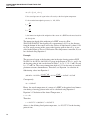
7 The Correction for the Pressure Difference . . . . . . . . . . 25
i
Figures
Figure 1
Figure 2
Figure 3
Figure 4
Figure 5
Figure 6
Figure 7
ii
The metal-cased freezing point cell.. . . . . . . . . . . . . . . . . . . . 6
The Model 5944/5945/5946/5947 metal-cased fixed-point cell . . . . . 10
Freezing curve comparison of one cell. . . . . . . . . . . . . . . . . . 14
Typical freeze point cell design showing the liquid-solid interfaces. . . 16
9114 Furnace Interior with Freeze Point Cell, Cross Sectional View. . . 17
9260 furnace interior with freeze point cell, cross sectional view.. . . . 19
A typical freezing curve for the Zinc Cell.. . . . . . . . . . . . . . . . 22
Tables
Table1
Table 2
Table 3
Table 4
Table 5
Table 6
Table 7
International Electrical Symbols . . . . . . . . . . . . . . . . . . . . . 1
The defining metal freezing points of the ITS-90, pressure constants,
and resistance ratios.. . . . . . . . . . . . . . . . . . . . . . . . . . . . 5
Some sub-ranges of the ITS-90 and freezing points required
for calibration. . . . . . . . . . . . . . . . . . . . . . . . . . . . . . . . 6
Specifications . . . . . . . . . . . . . . . . . . . . . . . . . . . . . . . 7
Summary of the 1st Cryoscopic Constants and the Estimated
Effects of Impurities . . . . . . . . . . . . . . . . . . . . . . . . . . . 14
The furnaces for fixed points and their temperature uniformity.. . . . . 20
Coefficients for the Pressure Difference of Some Defining
Fixed Points. . . . . . . . . . . . . . . . . . . . . . . . . . . . . . . . 25
iii
1 Before You Start
Symbols Used
1
1.1
Before You Start
Symbols Used
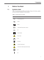
Table 1 lists the International Electrical Symbols. Some or all of these symbols
may be used on the instrument or in this manual.
Table1 International Electrical Symbols
Symbol
Description
AC (Alternating Current)
AC-DC
Battery
Complies with European Union directives
DC
Double Insulated
Electric Shock
Fuse
PE Ground
Hot Surface (Burn Hazard)
Read the User’s Manual (Important Information)
Off
On
1
5944/5945/5946/5947 Fixed Point Cell
User’s Guide
Symbol
Description
Canadian Standards Association
Australian EMC Mark
OVERVOLTAGE (Installation) CATEGORY II, Pollution Degree 2 per IEC1010-1 refers to
the level of Impulse Withstand Voltage protection provided. Equipment of
OVERVOLTAGE CATEGORY II is energy-consuming equipment to be supplied from the
fixed installation. Examples include household, office, and laboratory appliances.
The European Waste Electrical and Electronic Equipment (WEEE) Directive
(2002/96/EC) mark.
1.2
Safety Information
Use this instrument only as specified in this manual. Otherwise, the protection
provided by the instrument may be impaired.
The following definitions apply to the terms “Warning” and “Caution”.
“Warning” identifies conditions and actions that may pose hazards to the user.
“Caution” identifies conditions and actions that may damage the instrument being used.
1.2.1
Warnings
To avoid possible personal injury, follow these guidelines.
• DO NOT use this instrument for any application other than calibration
work.
• DO NOT use this instrument in environments other than those listed in the
user’s guide.
• Follow all safety guidelines listed in the user’s guide
• Calibration Equipment should only be used by Trained Personnel.
1.2.2
Cautions
To avoid possible damage to the instrument, follow these guidelines.
• Read the section entitled, Care and Handling Guidelines, before removing
the fixed point cell from the case. Incorrect handling can damage the cell.
• The fixed point cell must be kept in a vertical position. Placing the cell in
a horizontal position can damage the cell and void the warranty.
• DO NOT place the fixed point cell upside down
2
1 Before You Start
Authorized Service Centers
1.3
Authorized Service Centers
Please contact one of the following authorized Service Centers to coordinate
service on your Hart product:
Fluke Corporation, Hart Scientific Division
799 E. Utah Valley Drive
American Fork, UT 84003-9775
USA
Phone: +1.801.763.1600
Telefax: +1.801.763.1010
E-mail: [email protected]
Fluke Nederland B.V.
Customer Support Services
Science Park Eindhoven 5108
5692 EC Son
NETHERLANDS
Phone: +31-402-675300
Telefax: +31-402-675321
E-mail: [email protected]
Fluke Int'l Corporation
Service Center - Instrimpex
Room 2301 Sciteck Tower
22 Jianguomenwai Dajie
Chao Yang District
Beijing 100004, PRC
CHINA
Phone: +86-10-6-512-3436
Telefax: +86-10-6-512-3437
E-mail: [email protected]
Fluke South East Asia Pte Ltd.
Fluke ASEAN Regional Office
Service Center
3
5944/5945/5946/5947 Fixed Point Cell
User’s Guide
60 Alexandra Terrace #03-16
The Comtech (Lobby D)
118502
SINGAPORE
Phone: +65 6799-5588
Telefax: +65 6799-5588
E-mail: [email protected]
When contacting these Service Centers for support, please have the following
information available:
• Model Number
• Serial Number
• Complete description of the problem
4
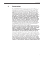
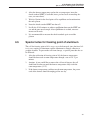
2 Introduction
2
Introduction
The International Temperature Scale of 1990 (ITS-90) is based on a series of
defining fixed points. At temperatures above 273.16 K, most of the fixed points
are the freezing points of specified pure metals. Pure metals melt and freeze at
a unique temperature through a process involving the absorption or liberation
of the latent heat of fusion. A metal freezing point is the phase equilibrium between the liquid phase and solid phase of a pure metal at a pressure of one standard atmospheric pressure (101,325 Pa). The freezing points of indium, tin,
zinc, aluminum, silver, gold, and copper are the defining fixed points of the
ITS-90. The temperature values of these freezing points assigned by the
ITS-90, the pressure effect constants and the resistance ratios at these fixed
points according to the ITS-90 SPRT reference function are listed in Table 2.
Table 2 The defining metal freezing points of the ITS-90, pressure constants, and
resistance ratios.
Pressure Effect of
Fixed Points
dt/dP
(10-8K/Pa)†
dt/dh
(10-3K/m)
Wr (T90)
dWr/dt
( x 0.001)
Fixed Point
Assigned Temperature
T90 (K)
t90 (°C)
FP In
429.7485
156.5985
4.9
3.3
1.60980185
3.801024
FP Sn
505.078
231.928
3.3
2.2
1.89279768
3.712721
FP Zn
692.677
419.527
4.3
2.7
2.56891730
3.495367
FP Al
933.473
660.323
7.0
1.6
3.37600860
3.204971
FP Ag
1234.93
961.78
6.0
5.4
4.28642053
2.840862
FP Au
1337.33
1064.18
6.1
10
--
--
FP Cu
1357.77
1084.62
3.3
† Equivalent to millikelvins per standard atmosphere.
2.6
--
--
All of these fixed points are intrinsic temperature standards according to the
definition of the ITS-90. Under controlled conditions these freezing points are
highly reproducible. The variance among different realizations of a freezing
point should be well within 1.0 mK for the freezing points of indium, tin and
zinc; and within a few millikelven for the freezing points of aluminum, silver,
gold, and copper. For your convenience Hart has developed a sealed cell design
and new technique for the realization of the freezing points, which has made it
easy to realize these fixed points.
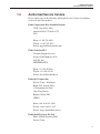
Model 5944/5945/5946/5947 metal-cased fixed-point cells are members of the
Hart fixed-point cell family (see Figure 1). The 5944/5945/5946/5947
fixed-point cells not only retain the merit of the lowest uncertainties of Hart
fused silica fixed-point cells (590X and 591X), but also provide a much stronger, more durable case. You will never worry about breaking the cell case
5
5944/5945/5946/5947 Fixed Point Cell
User’s Guide
again. The new cell can be shipped by conventional carrier eliminating the inconvenience of hand-carrying the cell from one place to another.
Figure 1 The metal-cased freezing point cell.
These freezing points are indispensable for the calibration of a standard platinum resistance thermometer (SPRT). Different sub-ranges require different sets
of freezing points, as summarized in Table 3.
Table 3 Some sub-ranges of the ITS-90 and freezing points required for calibration.
Subrange
0°C–961.78°C
0°C–660.323°C
0°C–419.527°C
0°C–231.928°C
0°C–156.5985°C
6
Freezing Points Required
FP Sn, FP Zn, FP Al, and FP Ag
FP Sn, FP Zn, and FP Al
FP Sn and FP Zn
FP In and FP Sn
FP In
3 Specifications and Environmental Conditions
Specifications
3
3.1
Specifications and Environmental
Conditions
Specifications
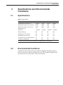
Table 4 Specifications
Model Number
5945
5946
5947
ITS-90 Assigned Temperature (°C)
156.5985
231.928
419.527
660.323
Expanded Uncertainty (°C) k=2, Cell Itself
0.0006
0.0008
0.001
0.002
Expanded Uncertainty (°C) k=2, Used in
9260, Melting Curve
0.0012
0.0016
0.002
0.004
Metal Purity
> 99.9999%
> 99.9999%
> 99.9999%
>99.9999%
Quantity of Metal (g)
660
655
648
200
Outer Diameter of the Cell (mm)
41.3
41.3
41.3
41.3
Overall Height of the Cell (mm)
222
222
222
222
Inner diameter of the Re-entrant Well (mm)
7.8
7.8
7.8
7.8
Total Immersion Depth† (mm)
156
156
156
156
†The
3.2
5944
distance from the bottom of the re-entrant well to the upper surface of the pure metal.
Environmental Conditions
Although the instrument has been designed for optimum durability and trouble-free operation, it must be handled with care. The instrument should not be
operated in an excessively dusty or dirty environment.
7
4 Construction
4
Construction
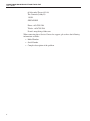
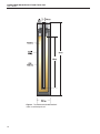
The 5944/5945/5946/5947 metal freezing point cell is shown in Figure 2. An
appropriate quantity of metal (See Table 4, Specifications, on page 7 for details) with a purity of 99.9999+% is melted into a graphite crucible with a
graphite lid and re-entrant well. The impurity in the graphite is less than 5
PPM. All of the graphite parts are subjected to a high-temperature, high-vacuum treatment before loading the metal sample. It is important to avoid any
possible contamination to the surface of the graphite parts during the manufacturing process. The assembled graphite crucible, with the high-purity metal, is
then enclosed in a metal-cased outer case and connected to a high vacuum system. The cell is drawn down to a proper pressure at a temperature near the
freezing point for several days. During this period the cell is purged with high
purity argon repeatedly to remove any contaminants. Finally, the cell is filled
with 99.999% pure argon and permanently sealed at the freezing point. The
pressure of the argon in the cell at the freezing point is closely adjusted to
101,325 Pa and the actual value of the pressure recorded. A small temperature
correction for the pressure difference can be made using the information in
Section 7, The Correction for the Pressure Difference.
The metal-cased cell is design to be used not only in primary fixed-point furnace (Model 9114), but also in small portable furnace (Model 9260). The total
depth of a portable furnace is only about 270 mm (10.6 inch), allowing short
probes to be calibrated by fixed point. On the top (the space above the
fixed-point cell) of the furnace a minimum of fifty-mm of thermal insulation is
required to maintain good vertical temperature uniformity in the cell. That
means that the total length of the cell is limited to about 220 mm. Therefore a
total immersion depth into the pure metal is 156 mm (Figure 2). The total immersion depth (156 mm) is a slightly more than is available in the 591X quartz
glass cell (140 mm), but less than that of 590X quartz glass cell (195 mm). We
pay special attention to decreasing, or eliminating thermal conduction error
during calibration at fixed points. Very thin metal tubing (0.01 inch thickness)
as the re-entrant well decreases the conductivity along the well to a minimum.
The tight match between the metal well and the graphite well improves thermal
conductivity in the radial direction, and decreases the thermal conduction error.
9
5944/5945/5946/5947 Fixed Point Cell
User’s Guide
Figure 2 The Model 5944/5945/5946/5947
metal-cased fixed-point cell
10
5 Care and Handling Guidelines
5
Care and Handling Guidelines
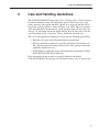
The 5944/5945/5946/5947 fixed-point cell is a delicate device. Great care must
be taken in handling, using and transporting the cell. The metal case is very
sturdy, however, the graphite crucible is brittle. It is suggested that the cell be
kept in the vertical position as shown in Figure 2 for safety. However, putting a
cold cell in horizontal orientation for a short period of time will not cause any
damage. Up side down orientation might damage the cell. Store the cell in the
vertical position and in a safe place. Always handle the cell with care.
The cell can be shipped by commercial carrier with the following preparation:
• Keep the cell in the vertical direction during transportation
• Put the cell into the wooden case specially designed for fixed-point cell
first, and then place the wooden cell case into a large package with foam
around the wooden cell case.
• Avoid bumping, shock and strong vibration during transportation. Utilize
Shock Watch and Tilt Watch indicators.
If the instructions in this manual are carefully followed, the Model
5944/5945/5946/5947 fixed-point cell will provide many years of accurate use.
11
6 Realization of the Fixed Point
Background Information
6
Realization of the Fixed Point
As was mentioned in Section 2, Introduction, it is not difficult to realize a
freezing point by using a Hart completely sealed metal freezing point cell. In
order to get the highest possible accuracy, a general understanding of the freezing process of an ideal pure metal is helpful.
6.1
Background Information
Theoretically the melting and freezing temperatures for an ideal pure metal are
identical. However, with the introduction of impurities in the metal, the melting
and freezing equilibrium points are usually slightly lower. The freezing plateau
of an ideal pure metal is conceptually flat. The only exception is during the
supercool. Impurities in the metal generally introduce a slightly negative slope
to the plateau. Most of the different types of impurities will cause a drop in the
freezing plateau e.g., gallium impurities in tin will cause a drop in the freezing
plateau. A few of the types of impurities can cause an increase in the plateau
e.g., gold impurities in silver will cause the freezing plateau to increase. An extremely high purity metal, 99.9999% or higher, behaves very closely to an ideal
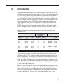
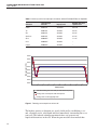
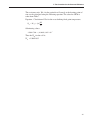
pure metal. Figure 3 shows the difference between a freeze of an ideal pure
metal and a high-purity metal. The approximate effect of the impurity on the
equilibrium point can be calculated using the first cryoscopic constant. This
calculation is discussed in the Guidelines for Realizing the International Temperature Scale of 1990 (ITS-90). For general uncertainty comparisons, the first
cryoscopic constant, the metal purity requirement, and the difference in the
liquidus point are outlined in Table 5. In a modern temperature standard laboratory using a SPRT, a temperature change as low as 0.01 mK (0.00001 °C) can
be detected. Therefore, the best technique for realizing the freezing point with a
real sample is one that measures a temperature nearest to the freezing point of
the ideal pure metal. The beginning of the very slow freezing curve of a high
purity metal is the closest temperature to the ideal freezing point which can be
obtained in a modern temperature standard laboratory. A so-called slow induced freezing technique was found to fit the purpose best (The detail of the
technique will be described a little later). A very slow freeze allows enough
time to calibrate a number of SPRTs in the beginning part of a single freeze.
13
5944/5945/5946/5947 Fixed Point Cell
User’s Guide
Table 5 Summary of the 1st Cryoscopic Constants and the Estimated Effects of Impurities
Substance
1st Cryoscopic
Constant
Impurity Level
Deviation from Pure
Liquidus Point
Indium
0.00732/K
99.99999%
-0.01 mK
Tin
0.00329/K
99.9999%
-0.3 mK
Zinc
0.00185/K
99.9999%
-0.5 mK
Aluminum
0.00149/K
99.9999%
-0.7 mK
Silver
0.000891/K
99.9999%
-1.1 mK
Gold
0.000831/K
99.9999%
--
Copper
0.000857/K
99.9999%
--
660.38
660.36
Temperature (°C)
660.34
660.32
660.30
660.28
660.26
660.24
660.22
0
2
4
6
8
10
12
14
16
18
20
Time (hours)
Theoretical freezing curve of an ideal pure metal without supercool
Freezing curve of an ideal pure metal with supercool
Freezing curve of a real high-purity metal
Figure 3 Freezing curve comparison of one cell.
The highest accuracy realizations are greatly facilitated by establishing a second, essentially static, solid-liquid interface immediately surrounding the re-entrant well. The induced technique mentioned above can generate two
liquid-solid interfaces in the cell. When the pure metal has been melted thor14
6 Realization of the Fixed Point
Background Information
oughly, maintain the furnace at 2°C above the freezing point overnight. The
next morning, decrease the furnace temperature to about 2°C below the freezing point at a rate of 0.5°C per minute. A SPRT inserted into the cell is used to
monitor the pure metal temperature. As soon as the recalescence (indicated
temperature stops to decrease and starts to rise) occurs, take the SPRT out of
the furnace and insert two cold quartz glass rods into the cell in succession,
each rod remains in the cell for about two minutes. Set the furnace to a temperature of about 0.5°C below the freezing point. The cold quartz glass rods absorb heat from the pure metal, and a thin film of pure metal is frozen around
the re-entrant well immediately. A continuous liquid-solid interface, as nearly
as is practical, encloses the sensor of the SPRT being calibrated. Another liquid-solid interface is formed on the wall of the graphite crucible. In this a situation, the outer interface advances slowly as the liquid continues to solidify.
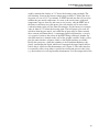
Ideally this generates a shell that continues to be of uniform thickness completely surrounding the liquid, which itself surrounds the inner liquid-solid interface that is adjacent to the thermometer well (Figure 4). The inner interface
is essentially static except when a specific heat-extraction process takes place;
e.g. the insertion of a cool replacement thermometer. It is the temperature of the
15
5944/5945/5946/5947 Fixed Point Cell
User’s Guide
inner liquid-solid interface that is measured by the thermometer. Sometimes the
inner liquid-solid interface is called the defining temperature interface.
Shell
Graphite Crucible
Liquid Sample
Solid Sample
Reentrant Tube
Melting State
Freezing State
Figure 4 Typical freeze point cell design showing the liquid-solid interfaces.
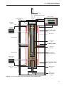
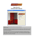
It is extremely important for the process described here that there is a very uniform, stable and controlled temperature environment enclosing the fixed-point
cell. We have developed several designs of fixed-point furnaces to satisfy these
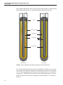
requirements. The Model 9114 furnace has three independent heaters and controllers designed to be used for a temperature range up to 680 °C as shown in
Figure 5.
16
6 Realization of the Fixed Point
Background Information
SPRT
Thermal Guard Assembly
Main Controller
SPRT Equilibration
Block
PRT Sensor
419.03 C
SET
DOWN
UP
EXIT
Top Zone
Heater
Top Zone
Controller
419.03 C
SET
DOWN
UP
TOP END ZONE
EXIT
Main Heater
Differential TCs
Freeze-Point
Cell
PRIMARY ZONE
Cell Support
Container
Differential TCs
Thermal Block
(3 zone subdivision)
Bottom Zone
Controller
419.03 C
SET
DOWN
UP
EXIT
BOTTOM END ZONE
Bottom Zone
Heater
Water Cooling
Coils
Supercooling
Gas Supply
(Argon)
Figure 5 9114 Furnace Interior with Freeze Point Cell, Cross Sectional View.
17
5944/5945/5946/5947 Fixed Point Cell
User’s Guide
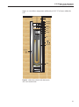
The 9260 small portable fixed-point furnace is much shorter than traditional
furnaces and can easily be used on a table or bench (Figure 6). The furnace has
a total height of 489 mm and an outer diameter of 209 mm, and it weights
about 17 kg. The 9260 permits simplified realization of either freezing or melting curves. Probes shorter than 430 mm (17") cannot be calibrated in the 9114
furnace. Probes at least 220 mm (9") in length can be calibrated in the 9260
furnace. Three heaters are used to obtain uniform temperatures around the
fixed-point cell. The main heater covers the furnace’s entire length, while the
top and bottom zone heaters cover only the upper and lower parts of the furnace, respectively. Only one controller is used in 9260. Software within the
unit’s controller is used to adjust the ratios of the three heaters. Using this tech-
18
6 Realization of the Fixed Point
Background Information
nique, we can achieve temperature uniformity of ±0.1°C or better within the
cell.
Top Insulation
Thermal Block
Thermal Shunt
Insulation
Basket Cover
Insulation
Basket
Sealed Cell
Heaters
Insulation
Thermal Well
Temperature
Control
Sensor
Cell Pad
Figure 6 9260 furnace interior with freeze point
cell, cross sectional view.
19
5944/5945/5946/5947 Fixed Point Cell
User’s Guide
Table 6 The furnaces for fixed points and their temperature uniformity.
Fixed Point
The Equipment Used
The freezing point of indium
Model 9114 furnace, three zones
Temperature Uniformity
± 0.01°C
The freezing point of tin
Model 9114 furnace, three zones
± 0.015°C
The freezing point of zinc
Model 9114 furnace, three zones
± 0.02°C
The freezing point of indium
Model 9260 furnace, three zones
± 0.05°C
The freezing point of tin
Model 9260 furnace, three zones
± 0.08°C
The freezing point of zinc
Model 9260 furnace, three zones
± 0.10°C
The cell should be put into the cell containment vessel before insertion into any
furnace. Ideally each cell would be kept in its own unique vessel. Fiber ceramic
insulation is placed in the bottom of the cell basket to protect the cell. Insulation is also placed on top of the cell for protection and to reduce heat loss.
6.2
6.2.1
Vertical Temperature Gradient and Controller
Accuracy Adjustment
Vertical temperature gradient adjustment
The vertical temperature gradient has to be within the required specification before a fixed point cell sample is melted. Otherwise, the cell may break. Therefore, the vertical temperature gradient should be measured each time the cell is
installed in a furnace, and checked at least every six months. The Model 9114
and 9260 Furnaces are three-zone furnaces, and their temperature gradient can
be adjusted through the top zone and the bottom zone heater.
Vertical temperature gradient test method
Set the furnace temperature 5°C below the melting point of the sample. For example, the melting point temperature of Zinc is 419.527°C; the furnace temperature should be set to 414.5°C. Maintain the temperature for at least 4 hours
(stabilizing) after the display temperature of the furnace reaches the set point
temperature. The SPRT is moved up 120 mm from the bottom of the thermometer well and then back to the bottom. The SPRT was moved in 40 mm increments and measurements taken at each depth. After every move and before
each measurement, a two-minute stabilization period was allowed.
The vertical temperature should meet the specification of the furnaces. Ideally
the temperature uniformity of 9114 and 9260 should meet the uniformity listed
in Table 6. If the furnace does not meet the requirement, the vertical temperature gradient should be adjusted through the top and bottom heater.
20
6 Realization of the Fixed Point
Procedure for Realizing the Freeze
6.2.2
Controller display accuracy adjustment
The absolute accuracy of the instrument might change after adjusting the temperature gradient, therefore it is important to check it after performing the vertical gradient adjustment. The offset in accuracy should be considered or
corrected during the realization of fixed points. The controller accuracy should
be checked after the sample is fully melted in every realization of a fixed point.
Please refer to the respective furnace Users Guide for a calibration procedure.
A calibrated SPRT should be used to measure the controller accuracy.
6.3
Procedure for Realizing the Freeze
All of the freezing points of metal-cased cells are realized manually in a similar
way.
1.
Insert the cell with the cell containment vessel carefully into the furnace.
Place as much thermal insulation material as possible onto the top of the
fixed-point cell (in the cell containment vessel and on the top of the
vessel).
2.
Set the temperature of the furnace about 5°C higher than the freezing
point. Allow all of the metal to melt completely.
3.
After all metal is completely melted, the furnace is set at a stable temperature about 2°C above the freezing point overnight.
4.
The next morning, the furnace temperature is decreased slowly (about
0.1°C per minute). In order to monitor the pure metal sample temperature, a SPRT is inserted into the cell. The temperature of the metal sample decreases to less than the freezing point before recalescence. The
amounts of supercool are different from metal-to-metal.
5.
After recalescence remove the thermometer from the furnace immediately and insert two cold (room temperature) quartz rods or tubes into the
fixed point cell one by one, keep each rod in the cell for two minutes.
6.
Set the furnace at a stable temperature of 0.5°C below the freezing point.
7.
Insert the preheated SPRT to be calibrated into the cell. Preheat the
SPRTs to be calibrated at a temperature of about 2°C above the freezing
point for thirty minutes before inserting them into the cell.
8.
It will take 30-40 minutes to get equilibrium between the SPRT sensor
and pure metal sample. After equilibrium reached you can start
measurements.
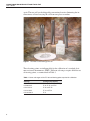
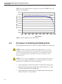
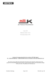
This procedure provides a very stable, long freezing plateau that typically lasts
for more than twenty hours. The changes in temperature in the first half of the
plateau are usually within ± 0.2–0.3 mK. A typical freezing curve is shown in
Figure 7.
Many SPRTs can be calibrated in a single freezing plateau. When multiple
21
5944/5945/5946/5947 Fixed Point Cell
User’s Guide
SPRTs are to be calibrated from a single freeze, preheat of SPRTs to be calibrated is very important.
0.6552574
F18 Bridge reading (Rt/Rs)
0.6552569
0.5 mK
0.6552564
0.6552559
0.6552554
0.6552549
0.6552544
0.6552539
0.6552534
0.6552529
10/8
10:00
10/8
13:00
10/8
16:00
10/8
19:00
10/8
22:00
10/9
1:00
10/9
4:00
10/9
7:00
10/9
10:00
10/9
13:00
Date and time
Figure 7 A typical freezing curve for the Zinc Cell.
6.4
Procedure for Realizing the Melting Point
The melting point of metal-cased cells are realized manually in a similar way.
NOTE: In order to optimize the Melting Point Realization, it is recommended to preheat all probes before inserting them into the metal-cased
cell. Probes can be preheated in a preheat well (not available on all furnaces) or annealing furnace operating at the same temperature of the
metal-cased cell.
NOTE: For new setup or installation, it is recommended that the melt plateau be monitored with an SPRT and recorded throughout the entire plateau. Doing so establishes the length of the plateau.
22
1.
Set the temperature of the furnace about 5°C below the freezing point.
2.
After the furnace temperature reaches the setting temperature, wait for
30 min for stabilization and equilibration.
3.
Set the temperature of the furnace 0.8°C higher than the freezing point
with a scan rate of 1.5°C per minute.
6 Realization of the Fixed Point
Special notes for freezing point of aluminum
6.5
4.
After the furnace temperature reaches the set temperature, insert the
check standard SPRT (if available) into a pre-heat well or annealing furnace (see note above).
5.
Wait for 30 min for the fixed-point cell to equilibrate and transition into
the melt plateau.
6.
Insert the check standard SPRT into the cell.
7.
It will take 30-40 minutes to achieve equilibrium between the SPRT sensor and the pure metal sample. After equilibrium is reached, measurements can be made.
8.
It is recommended to measure the check standard again to end the
plateau
Special notes for freezing point of aluminum
The cell for freezing point of Al is very easy to be damaged, since the fused silica is very sensitive to aluminum, and the aluminum is strongly adhesive to
graphite crucible. To prevent the cell from damage, a specific procedure has to
be followed:
1.
After the realization of freezing point of Al, the furnace temperature
should be decreased to room temperature through a rate of 1.8°C per
minute.
2.
Anytime, if you would like to remove the cell out of furnace, the cell
should not be taken out until the furnace temperature fully reach the
room temperature (22°C).
3.
If the furnace temperature could not reach room temperature, the power
cord of the furnace should be unplugged for one day.
23
7 The Correction for the Pressure Difference
7
The Correction for the Pressure Difference
This is the procedure used in the Hart metrology lab with the Hart sealed fixed
-point cells. Other procedures are sometimes employed in industry.
Except for a few triple points, the values of temperature assigned to the defining fixed points by ITS-90 correspond to the temperatures at the standard atmospheric pressure — 101.325 kPa. The actual pressure in a cell may be not
exactly the standard value. During the course of manufacture of a fixed-point
cell, it is easier to seal the cell if the pressure in the cell is a slightly lower than
the room pressure. The actual pressure in the cell exactly at the fixed point was
measured at Hart. This actual argon pressure in the cell at the freezing point is
provided on the Report of Test, or Certification, enabling calculation of correction for the difference in pressure. During measurement at a fixed point, the
sensor of a SPRT is usually placed at a height which is “h” meters lower than
the upper surface of the pure metal and where the pressure is higher than that at
the surface due to the static head. ITS-90 gives all of the necessary coefficients
for the calculation of the correction caused by the pressure difference, which
are summarized in following table:
Table 7 Coefficients for the Pressure Difference of Some Defining Fixed Points.
Assigned Value of
Equilibrium Temperature
T Kelvin (K)
Temperature with
Pressure, p k1;
dT/dp (10-5 mK/Pa)
Variation with depth
k2 : dT/dh (mK/m)
Approximate
dW/dt (1/K)
Argon (T)
83.8058
25
3.3
0.004342
Mercury (T)
234.3156
5.4
7.1
0.004037
273.16
-7.5
-0.73
0.003989
Gallium (M)
302.9146
-2.0
-1.2
0.003952
Indium (F)
429.7485
4.9
3.3
0.003801
Tin (F)
505.078
3.3
2.2
0.003713
Zinc (F)
692.677
4.3
2.7
0.003495
Substance
Water (T)
Aluminum (F)
933.473
7.0
1.6
0.003205
Silver (F)
1234.93
6.0
5.4
0.002841
Gold (F)
1337.33
6.1
10
--
Copper (F)
1357.77
3.3
2.6
--
(T) - Triple Point
(M) - Melting Point
(F) - Freezing Point
The correction of temperature caused by the difference in pressure can be calculated by using the following equation:
Equation 1: Pressure Dependent Temperature Correction
25
5944/5945/5946/5947 Fixed Point Cell
User’s Guide
Δt = ( P − P0 ) × k1 + h × k2
P: the actual pressure of argon in the cell exactly at the fixed point temperature
P0: the standard atmospheric pressure, i.e. 101,325 Pa
k1 =
dT
dP
k2 =
dT
dh
h: the immersion depth of the midpoint of the sensor of a SPRT into the matal used for
the fixed point
The immersion depth of the midpoint of a SPRT sensor in a Hart
5944/5945/5946/5947 fixed-point cell is approximately 0.131 m (the distance
from the bottom of the central well to the surface of liquid metal is about 0.156
m). The actual pressure of the argon at the freezing point in the cell, p, is provided in the Report of Test or Certification. The temperature correction, Δt, can
be calculated using Equation 1.
Example:
The pressure of argon at the freezing point in the zinc freezing point cell S/N
Zn-45001 is 86,100 Pa (86.10 kPa) as given in the Report of Test. k1 and k2 for
the freezing point of zinc can be found in Table 7, k1 = 4.3 * 10 –5 mK / Pa and
k2 = 2.7 mK / m. The average immersion depth is 0.131 m for most of standard
platinum resistance thermometers. Therefore, use Equation 1 to calculate Δt.
Substituting values into Equation 1:
(86100 Pa − 101325Pa )
4.3 × 10 −5 mK
2.7mK
+ 0131
. m
= −0.65mK + 0.35mK
Pa
m
Consequently:
Δt = −0.301mK
Hence, the actual temperature of a sensor of a SPRT at the point of total immersion during a freezing plateau in the cell is calculated using Equation 2.
Equation 2: Calculation of the Actual Temperature, t1
t 1 = t + Δt
Therefore:
t1 = 419.527°C − 0.000301°C = 419.5267°C
where t is the defining fixed point temperature, i.e. 419.527°C for the freezing
point of zinc.
26
7 The Correction for the Pressure Difference
The resistance ratio, WZn, for the particular cell exactly at the freezing point of
zinc can be calculated using the following equation. The value for dW/dt is
taken from Table 7.
Equation : Calculation of WZn for the exact defining fixed point temperature.
WZn = W ( t1 ) − [Δt ]
dW
dt
Substituting values:
2.568917300 − ( −0.00301)3.495 × 10 −3
Thus the WZn for the cell is:
WZn = 2.56891835
27