1
Signal Integrity Analyzer 3000
GPIB Programming Guide
200007-05
REV A
This page intentionally left blank.
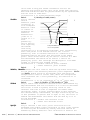
WAVECREST Corporation continually engages in research related to
product improvement. New material, production methods, and design
refinements are introduced into existing products without notice as a
routine expression of that philosophy. For this reason, any current
WAVECREST product may differ in some respect from its published
description but will always equal or exceed the original design
specifications unless otherwise stated.
Copyright 2005
WAVECREST Corporation
A Technologies Company
7626 Golden Triangle Drive
Eden Prairie, Minnesota 55344
(952) 831-0030
(800) 733-7128
www.wavecrest.com
All Rights Reserved
U.S. Patent Nos. 4,908,784 and 6,185,509, 6,194,925, 6,298,315 B1, 6,356,850
6,393,088, 6,449,570 and R.O.C. Invention Patent No. 146548; other United States
and foreign patents pending.
WAVECREST,
Corporation.
SIA-3000, GigaView, Remote GigaView and TailFit are trademarks of WAVECREST
PCI Express is a registered trademark of PCI-SIG in the United States and/or other countries. Visual
Basic is a registered trademark of Microsoft Corporation. LabVIEW is a registered trademark of
National Instruments Corporation.
ATTENTION: USE OF THE SOFTWARE IS SUBJECT TO THE WAVECREST SOFTWARE LICENSE TERMS
SET FORTH BELOW. USING THE SOFTWARE INDICATES YOUR ACCEPTANCE OF THESE LICENSE
TERMS. IF YOU DO NOT ACCEPT THESE LICENSE TERMS, YOU MUST RETURN THE SOFTWARE FOR A
FULL REFUND.
WAVECREST SOFTWARE LICENSE TERMS
The following License Terms govern your use of the accompanying Software unless you have a separate written
agreement with Wavecrest.
License Grant. Wavecrest grants you a license to use one copy of the Software. USE means storing, loading, installing,
executing or displaying the Software. You may not modify the Software or disable any licensing or control features of
the Software.
Ownership. The Software is owned and copyrighted by Wavecrest or its third party suppliers. The Software is the
subject of certain patents pending. Your license confers no title or ownership in the Software and is not a sale of any
rights in the Software.
Copies. You may only make copies of the Software for archival purposes or when copying is an essential step in the
authorized Use of the Software. You must reproduce all copyright notices in the original Software on all copies. You
may not copy the Software onto any bulletin board or similar system. You may not make any changes or modifications
to the Software or reverse engineer, decompile, or disassemble the Software.
Transfer. Your license will automatically terminate upon any transfer of the Software. Upon transfer, you must deliver
the Software, including any copies and related documentation, to the transferee. The transferee must accept
these License Terms as a condition to the transfer.
Termination. Wavecrest may terminate your license upon notice for failure to comply with any of these License
Terms. Upon termination, you must immediately destroy the Software, together with all copies, adaptations and
merged portions in any form.
Limited Warranty and Limitation of Liability. Wavecrest SPECIFICALLY DISCLAIMS ALL OTHER
REPRESENTATIONS, CONDITIONS, OR WARRANTIES, EITHER EXPRESS OR IMPLIED, INCLUDING BUT
NOT LIMITED TO ANY IMPLIED WARRANTY OR CONDITION OF MERCHANTABILITY OR FITNESS
FOR A PARTICULAR PURPOSE. ALL OTHER IMPLIED TERMS ARE EXCLUDED. IN NO EVENT WILL
WAVECREST BE LIABLE FOR DIRECT, INDIRECT, SPECIAL, INCIDENTAL, OR CONSEQUENTIAL
DAMAGES ARISING OUT OF THE USE OF OR INABILITY TO USE THE SOFTWARE, WHETHER OR NOT
WAVECREST MAY BE AWARE OF THE POSSIBILITY OF SUCH DAMAGES. IN PARTICULAR,
WAVECREST IS NOT RESPONSIBLE FOR ANY COSTS INCLUDING, BUT NOT LIMITED TO, THOSE
INCURRED AS THE RESULT OF LOST PROFITS OR REVENUE, LOSS OF THE USE OF THE SOFTWARE,
LOSS OF DATA, THE COSTS OF RECOVERING SUCH SOFTWARE OR DATA, OR FOR OTHER SIMILAR
COSTS. IN NO CASE SHALL WAVECREST'S LIABILITY EXCEED THE AMOUNT OF THE LICENSE FEE
PAID BY YOU FOR THE USE OF THE SOFTWARE.
Export Requirements. You may not export or re-export the Software or any copy or adaptation in violation of
any applicable laws or regulations.
U.S. Government Restricted Rights. The Software and documentation have been developed entirely at private
expense and are provided as Commercial Computer Software or restricted computer software.
They are delivered and licensed as commercial computer software as defined in DFARS 252.227-7013 Oct 1988,
DFARS 252.211-7015 May 1991 or DFARS 252.227.7014 Jun 1995, as a commercial item as defined in FAR 2.101 (a),
or as restricted computer software as defined in FAR 52.227-19 Jun 1987 or any equivalent agency regulations or
contract clause, whichever is applicable.
You have only those rights provided for such Software and Documentation by the applicable FAR or DFARS clause or
the Wavecrest standard software agreement for the product.
Table of Contents
Purpose and Organization of this Manual................................................. vii
Section 1
GPIB Interface
1-1
1-2
1-3
1-4
1-4.1
Section 2
GPIB Commands and Status
2-1
2-2
2-3
2-4
Section 3
Summary and Rules of SIA-3000 GPIB Commands.................... 5
IEEE-488.1 Bus Commands (Hardware)...................................... 6
Common Commands .................................................................... 7
Root Commands............................................................................ 8
Common Commands and Statusing
3-1
3-1.1
3-1.2
3-2
3-3
3-4
3-5
3-6
3-7
3-8
3-9
3-10
3-11
3-12
3-13
3-14
Section 4
Introduction to Remote Programming of the SIA-3000 ............. 1
SIA-3000 Syntax........................................................................... 1
IEEE-488.2 Bus Commands ......................................................... 2
IEEE-488.2 Protocol ..................................................................... 2
Protocol Exceptions ...................................................................... 3
Description of the Common Commands & Status........................ 9
Bit Definitions............................................................................... 11
Key Features ................................................................................. 12
*CLS - Clear Status Command..................................................... 13
*ESE - Event Status Enable Command/Query ............................. 14
*ESR? - Event Status Register Query........................................... 15
*IDN? - Identification Number Query.......................................... 16
*OPC - Operation Complete Command/Query ............................ 16
*OPT - Options Query .................................................................. 16
*RCL - Recall Command.............................................................. 16
*RST - Reset Command ............................................................... 17
*SAV - Save Command................................................................ 17
*SRE - Service Request Enable Command/Query ....................... 18
*STB? - Status Byte Query........................................................... 19
*TRG - Trigger Event Register Query.......................................... 20
*TST? - Test Instrument Query .................................................... 20
Root Commands
4-1
4-2
4-3
4-4
4-5
©WAVECREST Corporation 2005
Description of the Root Commands.............................................. 21
LER? ............................................................................................. 21
RUN .............................................................................................. 21
SDS? ............................................................................................. 21
TER? ............................................................................................. 22
GPIB Programming Guide
iii
Table of Contents
Section 5
Basic Measures GPIB Commands
5-1
5-2
5-3
5-4
5-5
5-6
5-7
5-8
5-9
5-10
5-11
5-12
Section 6
iv
Introduction to Basic Measures Commands ................................. 23
Acquire Commands ...................................................................... 24
Calibrate Commands..................................................................... 29
CDR Commands ........................................................................... 31
Channel Commands ...................................................................... 33
Display Commands....................................................................... 35
File Commands ............................................................................. 37
Global Commands ........................................................................ 38
Marker Commands........................................................................ 39
Measure Commands...................................................................... 42
System Commands........................................................................ 47
Trigger Commands ....................................................................... 55
Tool Oriented GPIB Commands ........................................................ 57
6-1
6-2
6-3
6-4
6-5
6-6
6-7
6-8
6-9
6-10
6-11
6-12
6-13
6-13
6-14
6-15
6-16
6-17
6-18
6-19
6-20
6-21
6-22
6-23
6-24
6-25
6-26
6-27
6-28
6-24
6-25
6-26
6-27
6-28
Serial ATA Gen2i&Gen2m Commands ....................................... 59
Serial ATA Gen1x &Gen2x Commands ...................................... 71
Bit Clock and Marker Commands ................................................ 81
Channel-to-Channel Locktime Commands................................... 93
Clock Analysis Commands..........................................................105
Clock Statistics Commands .........................................................119
Cycle-to-Cycle Commands..........................................................129
Databus Commands .....................................................................145
DRCG Commands .......................................................................159
PCI Express 1.1 w/Software Clock Recovery .............................167
Feature Analysis Commands .......................................................181
Fibre Channel Commands............................................................187
Folded Eye Diagram Commands .................................................195
High Frequency Modulation Commands.....................................205
Histogram.....................................................................................217
InfiniBand Commands .................................................................233
Known Pattern with Marker Commands .....................................243
Low Frequency Modulation Commands .....................................261
Locktime Commands ...................................................................271
PCI Express 1.1 w/Hardware Clock Commands .........................285
PCI Express Commands ..............................................................297
PCI Express Clock Analysis Commands.....................................309
Phase Noise Commands...............................................................321
PLL Analysis Commands ............................................................331
Random Data No Marker Commands..........................................345
Random Data with Bit Clock Commands....................................353
Serial ATA Commands................................................................363
Scope Commands.........................................................................369
Simple Commands .......................................................................385
Skew and Propagation Delay Commands....................................393
Spread Spectrum Clock Analysis Commands ............................409
Statistics Commands....................................................................409
Stripchart Channel-to-Channel Commands .................................429
Stripchart Commands...................................................................439
GPIB Programming Guide
©WAVECREST Corporation 2005
Table of Contents
Section 7
Binary Packet Measurements
7-1
7-2
7-3
7-4
7-5
7-6
7-7
7-8
7-9
7-10
7-11
7-12
7-13
7-14
7-15
7-16
7-17
7-18
7-19
7-20
7-21
7-22
7-23
7-24
7-25
7-26
7-27
7-28
7-29
7-30
7-31
7-32
7-33
7-34
7-35
7-36
7-37
7-38
7-39
7-40
7-41
7-42
7-43
Introduction .................................................................................449
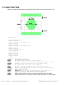
Binary Packet Structure Overview...............................................450
Plot Data Structure.......................................................................451
Acquisition Parameter Structure ..................................................452
TailFit Result Structure................................................................455
Single Side of TailFit Structure ...................................................455
Specification Limit Structure.......................................................456
DDJ + DCD Data Structure .........................................................457
Pattern Structure...........................................................................457
FFT Window and Analysis Structure ..........................................458
QTYS Structure ...........................................................................459
MEAS Structure...........................................................................460
OHIS Structure.............................................................................461
MASK Structure ..........................................................................461
KPWM Structure .........................................................................463
Adjacent Cycle Jitter Tool ...........................................................470
Clock Analysis Tool ....................................................................475
Clock Statistics Tool ....................................................................478
Databus Tool................................................................................480
Datacom Bit Clock and Marker Tool...........................................482
Datacom Known Pattern with Marker Tool.................................485
Datacom Random Data with Bit Clock Tool...............................495
Datacom Random Data with No Marker Tool.............................501
Fibre Channel Compliance Tool..................................................504
Folded Eye Diagram Tool............................................................507
High Frequency Modulation Analysis Tool ................................505
Histogram Tool ............................................................................510
InfiniBand Tool............................................................................513
Locktime Analysis Tool...............................................................514
Low Frequency Modulation Analysis Tool .................................517
Oscilloscope Tool ........................................................................519
PCI Express 1.1 w/Hardware Clock Recovery Tool ...................520
PCI Express 1.1 w/Software Clock Recovery Tool.....................522
PCI Express 1.1 Clock Analysis Tool .........................................525
PCI Express 1.0a Tool .................................................................527
Phase Noise Tool .........................................................................529
PLL Analysis Tool.......................................................................531
Rambus DRCG Tool....................................................................533
Scope Tool ...................................................................................535
Serial ATA Gen2i & Gen2m Tool...............................................539
Serial ATA Gen1x & Gen2x Tool ...............................................541
Serial ATA 1.0a Tool...................................................................542
Spread Spectrum Tool..................................................................544
©WAVECREST Corporation 2005
GPIB Programming Guide
v
Table of Contents
7-44
7-45
7-46
7-47
7-48
7-49
Appendix A
StatisticsTool................................................................................547
Stripchart Tool .............................................................................549
Retrieving Spikelists ....................................................................552
Retrieving Plot Data.....................................................................553
Example of How to Draw Using a Plot Structure........................554
Defines for Values in Binary Packet Structures ..........................555
Internal & External Calibration
Internal .....................................................................................................559
Deskew.....................................................................................................560
Deskew with DC Offset ...........................................................................561
Strobe .......................................................................................................565
vi
Appendix B
Reading Data ............................................................................................567
Appendix C
Data Types .................................................................................................569
GPIB Programming Guide
©WAVECREST Corporation 2005
Purpose and Organization of this Manual
The WAVECREST SIA-3000 and GigaView™ software have the ability to run automated tests or control the SIA
remotely through a workstation or PC. There are several programming methods for achieving this: GPIB, Production
API (PAPI), LabVIEW™, Remote GigaView™ and Visual Basic Macros.
Each approach has advantages or disadvantages depending on the situation in which the technique will be used. For
example, a low level GPIB command set may require more time to understand and program—a negative—but provides
extremely fast measurements that are used in a production environment—a benefit. On the other hand, Visual Basic
Script Macros provide ease of use from the front panel, but would not typically be used in a production environment.
This manual is divided into sections describing the purpose and general implementation of each method including
detailed GPIB command definitions and examples. Additionally, example code is provided and some general
applications of each implementation are described. This manual also provides command references/definitions for all
tools, commands or structures.
It is assumed that the user has some familiarity with GPIB usage. The user should be familiar with the concepts of
selecting an interface, device addressing, interface initialization as well as the command structure and format for
programming an instrument over the GPIB.
The manual has been organized as follows:
Section 1– GPIB Interface
Introduction to Remote Programming of the SIA-3000 including general syntax and protocols.
Section 2 – Summary of GPIB Commands
This section lists the common, root, bus and subsystem commands and gives an overview of the basic structure of
commands.
Section 3 – Common Commands and Status
This section provides in-depth definitions of the common commands, including example code, and how they are used
during status reporting,
Section 4 – Root Commands
This section provides in-depth definitions of the root commands including example code.
Section 5 – Basic Measures GPIB Commands
The Basic Measures command set is the “lowest” level of the three GPIB command sets that can be implemented. It
provides essential signal measurements such as Period/Pk-Pk/1-sigma and skew. It is also the fastest method and is
used mostly in ATE or production environments.
Section 6 – Tool Oriented GPIB Commands
The Tool Oriented GPIB commands provide a larger command set of measurement tools that go beyond the ‘Basic Measures
GPIB’. When a certain functionality of a tool needs to be accessed or set up, these commands provide that capability.
Section 7 – Binary Packet Structures and Commands
This command set allows you to perform measurements from all of the tools while minimizing GPIB bus traffic.
It optimizes speed but is more machine friendly than user friendly.
Appendix A contains internal and deskew calibration instructions including example programs.
Appendix B describes the programming steps for taking and reading measurement values.
Appendix C
describes the data formats used for transferring data from the SIA-3000 over the GPIB bus for
:MEASure commands.
©WAVECREST Corporation 2005
vii
This page intentionally left blank.
viii
©WAVECREST Corporation 2005
SECTION 1- GPIB INTERFACE BASICS
1-1
INTRODUCTION TO REMOTE PROGRAMMING OF THE SIA-3000™
You can program the SIA-3000 to:
•
•
Set up the SIA-3000 and start a measurement.
Return the setup parameters and measurements to the GPIB controller.
Other tasks are accomplished by combining the basic functions.
It is assumed that you are familiar with the usage of the GPIB. If you are not, please consult your
GPIB documentation. In particular, you should be familiar with the concepts of selecting an
interface, device addressing, interface initialization as well as the command structure and format for
programming an instrument over the GPIB.
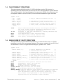
1-2
SIA-3000 SYNTAX
The mnemonic representing the operation to be performed by the instrument is known as the
“command header.” There are different types of command headers that are discussed in more
detail in the following paragraphs. Commands may be simple or compound. The simple command
headers consist of a single mnemonic, while a compound command header contains two or more
program mnemonics. The first mnemonic of a compound header selects a subsystem and the last
mnemonic selects the desired function within the subsystem. Mnemonics, within a compound
message, are separated by colons.
•
To execute a simple command, the syntax is:
<mnemonic><terminator>
Example: “:RUN”
•
To execute a simple command with data:
<mnemonic><separator><data><terminator>
Example: “*SAV 1”
•
To execute a single function in a subsystem (a compound command):
<Subsystem>:<function><separator><data><terminator>
Example: “SYSTem:CHANnel 1”
In addition to the simple and compound command headers, there are also common command
headers to control generic functions in the SIA-3000. An example of a common command
function is “reset.” The syntax for common command headers is:
*<command header><terminator>
Example: “*RST”
Note that no space or other separator is allowed between the asterisk and the command header.
©WAVECREST Corporation 2005
Section 1 | GPIB Interface | 1
If a command header is immediately followed by a question mark, then the command is a query.
After a query is received, the SIA-3000™ responds by placing a response in the GPIB output
queue. The response will stay in the queue until either the controller reads the response or another
command is issued by the controller.
The program commands from the controller are case insensitive: either lower or uppercase letters
may be used. The SIA-3000 will always respond using upper case. Either the long form (the
complete spelling of a command) or the short form (abbreviated spelling) may be used.
The terminator for a message can be a NL (new line, ASCII 10) character, asserting the GPIB EOI
(End-Or-Identify) signal or a combination of both. All three ways are equivalent.
It is possible to send multiple commands and queries to different subsystems in the same
command by separating each command with a semicolon. Multiple commands may be any
combination of compound and simple commands.
1-3
IEEE-488.2 BUS COMMANDS
IEEE-488.2 defines the action of the SIA-3000 for certain bus commands. A device clear
(DCL) or selected device clear (SDR) command clears both the input and output buffers. The
parser is reset, and any pending commands are cleared.
The group execute trigger (GET) command causes the same action as the RUN/GO command.
The interface clear (IFC) command halts any bus activity. Control is returned to the system
controller, and any command in progress is terminated.
The following commands are IEEE-488.1 bus commands (hardware line ATN true).
Clear Interface (IFC) - Halts all bus activity.
Device Clear - The device clear (DCL) command causes the device to perform a clear.
Group Execute - Performs the same action as the trigger GET, RUN and *TRG commands.
(The device will acquire data.)
1-4
IEEE-488.2 PROTOCOL
The IEEE-488.2 standard defines the overall scheme for communication with the SIA-3000.
Please consult the IEEE-488.2 standard for further clarification of the protocol.
The communications subsystem of the SIA-3000 consists of an input buffer and an output buffer.
The input buffer is a memory area where commands and queries from the controller are stored and
processed. The input buffer holds 274 characters or bytes of data.
The output buffer is a memory area where data for the controller is stored until read. The output
area is large enough to hold 510 characters or bytes of data. Larger blocks of data are handled by
breaking the data into a series of blocks smaller than 510 bytes in size.
The SIA-3000’s command parser interprets commands from the controller and determines what
action to take in response.
After power up, or after receiving a device clear command, both the input and output buffers are
cleared and the parser is reset. The controller and the SIA-3000 communicate by exchanging
program and response messages. The controller should always terminate a program message
before reading a response from the SIA-3000.
2 | Section 1 | GPIB Interface
©WAVECREST Corporation 2005
If the controller sends a query message to the SIA-3000, the next message from the controller
should be a response message. The controller should read the entire response from the SIA3000 before sending another query message.
Execution of commands by the SIA-3000 is in the order that the commands are received. This
also includes reception of the group execute trigger (GET) bus command. The controller should
not send a group execute trigger command in the middle of a program message.
It is possible to send multiple queries in a query message (“compound query”) by use of semicolon
message separators. The SIA-3000 responses to a multiple query will also be separated by
semicolons.
1-4.1 PROTOCOL EXCEPTIONS
If the SIA-3000 is addressed to talk before the controller sent it a query, it will indicate a query
error and not transmit any data bytes over the GPIB. If the SIA-3000 has no response because it
was unable to execute the query because of an error, the SIA-3000 will not indicate a query
error, and waits for the next message from the controller.
If a command error occurs, it is reported to the controller. An example of a command error would
be a syntax error or an unrecognized command. A group execute trigger in the middle of a program
message is also considered a command error.
If a parameter is out of range, or the current settings of the SIA-3000 will not allow execution
of a requested command or query, then an execution error is reported to the controller.
A device-specific error will be reported by the SIA-3000 if it is unable to execute a command for
a strictly SIA-3000 dependent reason.
A query error will be reported if the proper protocol for a query is not followed. Query errors
include both “unterminated” and “interrupted” conditions.
If the controller attempts to read a response message before the program message has been
terminated (an “unterminated” condition), the SIA-3000 reports a query error. The parser is
reset, and any response is cleared from the output buffer, without being sent back to the controller.
If the controller fails to read the entire response message and attempts to send another program
message, the SIA-3000 responds with a query error. The unread portion of the response is
discarded by the SIA-3000. The program message from the controller is not affected, and will
be processed normally by the SIA-3000.
It is possible for the SIA-3000 to become deadlocked in a condition where both the input and
output buffers are full. This can occur if the controller sends a very long program message
which contains queries that generate a large number of data bytes in response. The SIA-3000 is
unable to accept any more program message bytes under this condition, but the controller
cannot read any of the response data bytes until the entire program message has been sent to the
SIA-3000. If this situation occurs, the SIA-3000 detects the condition, clears the output queue,
and discards responses until it reaches the end of the program message. A query error bit is also
set under this condition.
©WAVECREST Corporation 2005
Section 1 | GPIB Interface | 3
This page intentionally left blank.
4 | Section 1 | GPIB Interface
©WAVECREST Corporation 2005
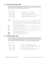
SECTION 2 - GPIB COMMANDS
2-1
SUMMARY OF SIA-3000 COMMANDS
In addition to the Common commands (see section 2.3) defined for all instruments by IEEE-488.2,
the instrument subsystem commands used in the SIA-3000 are:
Acquire - Provides access to the parameters for acquiring and storing data.
Calibrate - Provides for the selection of different calibrate functions and retrieves data
generated by these functions.
Channel - Provides access to the parameters associated with the different channels.
Display - Provides access to the parameters for controlling how or what information will be
displayed.
Measure - Selects the measurements to be made.
Plot - Provides access to the plot data recorded from a previously called
:ACQ:<API structure> command.
System - Controls some basic functions of the SIA-3000.
Trigger - Controls the trigger modes and parameters for each trigger mode.
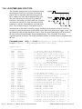
The following legend is used in the instrument subsystem commands:
<n> - Represents any single channel number between 1 and 10 (required)
<a> - Represents any single arming input between ARM1 and ARM10 (required)
(@ <n,m,x,…>|<n:m>) - Represents an optional channel list/range of channels between 1 and 10
•
For single channel measurements, valid commands include:
:ACQ:ALL PER (@10), :ACQ:ALL PER (@ 1,3,5) and :ACQ:ALL PER (@7:10)
•
For dual channel (parallel) measurements, the ampersand symbol appears between the
reference channel and multiple measurement channels. Only one set of parallel measurements
can be sent in a single command. For example:
:ACQ:ALL TPD++ (@ 1&2,4,5)
(TPD ++ measurements on reference channel 1, data channels 2, 4 and 5)
:ACQ:ALL TPD++ (@ 2&3:8)
(TPD++ measurements on reference channel 2, data channels 3 through 8)
©WAVECREST Corporation 2005
Section 2 | Common Commands | 5
Rules for Using a Channel List or Range:
•
If the channel list is absent, the command is executed using the current measurement channel
•
The channels must be entered in ascending order
•
If the range of channels specified includes an inactive channel, the device will report an error
•
If a measurement error occurs on one of the requested channels, values that indicate a bad
measurement will be returned/displayed and the device will attempt to measure the remaining
channels in the list
Rules for Using the Group (Pseudo-Parallel) Commands:
•
To create a group of commands, send the :SYST:GROUP<n>ON command, where n
represents a group between 1 and 20
•
Any commands sent after this command will now be queued inside the device as a group
until the :SYST:GROUP<n>OFF is sent. Only one group will be queued at a time.
•
When the :ACQ:GROUP<n> command is sent, all of the queued commands within that
group will be executed in the order they were received. If any of the commands in the group
request data to be sent back, the data will be sent back in the order requested
•
All of the commands described in this document can be included in a group except for the
following:
- Common and Root commands listed in Sections 2-3 and 2-4
- :SYSTem:HEADer, :SYSTem:LONGform, :SYSTem:COMPatible,
:SYSTem:ADDRess, :SYSTem:ENDian, :SYSTem:TEST, :SYSTem:GO,
:SYSTem:NOGO, :SYSTem:STROBeCAL (Section 2-5)
- :CALIBRATE commands (Section 2-7)
2-2
IEEE-488.1 BUS COMMANDS (HARDWARE)
The following commands are IEEE-488.1 bus commands (hardware line ATN true).
Clear Interface (IFC) - Halts all bus activity.
Device Clear - The device clear (DCL) command causes the device to perform a clear.
Group Execute - Performs the same action as the trigger GET, RUN and *TRG commands.
(The device will acquire data.)
6
| Section 2 | Common Commands
©WAVECREST Corporation 2005
2-3
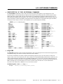
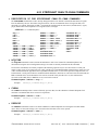
COMMON COMMANDS
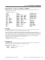
The following are common commands defined by IEEE-488.2 and supported by the SIA-3000.
*CLS ............................Clear Status.
*ESE ............................Event Status Enable.
*ESE ............................Query.
*ESR ............................Event Status Register Query.
*IDN ............................Identification Query.
*OPC ............................Operation Complete.
*OPC?..........................Query.
*OPT ............................Returns the list of instrument options.
*RCL ........<0-10>........Recall.
*RST ............................Reset. Resets the input and output buffers, resets the parser and
clears any pending commands.
*SAV ........<0-10>........Save.
*SRE ...........................Service Request Enable.
*SRE?..........................Query.
*STB?..........................Status Byte Query.
*TRG ............................Causes the SIA-3000 to initiate a measurement.
*TST?..........................Test Instrument Query.
©WAVECREST Corporation 2005
Section 2 | Common Commands | 7
2-4
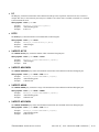
ROOT COMMANDS
:RUN - Causes the SIA-3000 to initiate measurement. Does the same function as the *TRG.
:TER? - This query will read the identified TRG Event Register. When the register is read,
it is cleared. A one (1) informs the program that the trigger has occurred. Monitor
this bit to know when a take sample (burst), pulse find, cable measure or an
internal/external calibration is complete.
:LER? - This query will read the Local Event Register. When the query is received and the
register is read, it is cleared. A non-zero indicates that a reset is in progress.
:SDS? - This query reads the Special Device Register. When the query is received and the
register is read, it is cleared. This register is used to indicate when some commands
are complete when they don’t set a TRG or MAV bit. Same as bit 3 of a serial poll.
8
| Section 2 | Common Commands
©WAVECREST Corporation 2005
SECTION 3 - Common Commands & Status
3-1
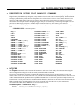
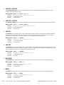
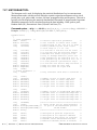
DESCRIPTION OF THE COMMON COMMANDS & STATUS
IEEE-488.2 defines a set of common commands. These commands perform functions that are
common to any type of instrument. They can therefore be implemented in a standard way across a
wide variety of instrumentation. All the common commands of IEEE-488.2 begin with an asterisk.
There is one key difference between the IEEE-488.2 common commands and the rest of the
commands found in this instrument. The IEEE-488.2 common commands do not affect the parser’s
position within the command tree. Many of these commands are used for status.
Command
Command Name
*CLS ............................Clear Status.
*ESE ............................Event Status Enable.
*ESE?..........................Event Status Enable Query.
*ESR?..........................Event Status Register Query.
*IDN?..........................Identification Query.
*OPC ............................Operation Complete.
*OPC?..........................Operation Complete Query.
*OPT ............................Returns the list of installed options.
*RCL ........<0-10>........Recall.
*RST ............................Reset. Resets the input and output buffers, resets the parser and
clears any pending commands.
*SAV ........<0-10>........Save.
*SRE ...........................Service Request Enable.
*SRE?..........................Service Request Query.
*STB?..........................Status Byte Query.
*TRG ............................Causes the SIA-3000 to initiate a measurement.
*TST?..........................Test Instrument Query.
The bits in the status byte act as summary bits for the data structures residing behind them. In
the case of queues, the summary bit is set if the queue is not empty. For registers, the summary
bit is set if any enabled bit in the event register is set. The events are enabled via the corresponding
event enable register. Events captured by an event register remain set until the register is read or
cleared. Registers are read with their associated commands. The “*CLS” command clears all event
registers and all queues except the output queue. If “*CLS” is sent immediately following a
<program message terminator>, the output queue will also be cleared.
©WAVECREST Corporation 2005
Section 3 | Common Commands and Status | 9
10 | Section 3 | Common Commands and Status
©WAVECREST Corporation 2005
3-1.1
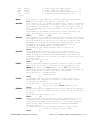
BIT DEFINITIONS
CME - Command error. Indicates whether the parser detected an error.
DDE - Device specific error. Indicates whether the device was unable to complete an operation
for device dependent reasons.
ESB - Event status bit. Indicates if any of the conditions in the Standard Event Status Register
are set and enabled.
EXE - Execution error. Indicates whether a parameter was out of range, or inconsistent with
current settings.
LCL - Indicates whether a remote to local transition has occurred. Indicates when a Device
Clear (DCL) is complete.
MAV - Message available. Indicates whether there is a response in the output queue.
MSS - Master summary status. Indicates whether the device has a reason for requesting service.
This bit is returned for the *STB? query.
OPC - Operation complete. Indicates whether the device has completed all pending operations.
OPT – Options. Returns a list of installed options.
PON - Power on. Always 1.
QYE - Query error. Indicates whether the protocol for queries has been violated.
RQC - Request control. Indicates whether the device is requesting control. Asking for a
simulated GO key to be executed.
RQS - Indicates if the device is requesting service. This bit is returned during a serial poll. RQS
will be set to 0 after being read via a serial poll (MSS is not reset by *STB?).
SDS - Special device status.
TRG - Indicates whether a trigger has been received.
URQ - User request. Indicates whether a front panel key has been pressed.
©WAVECREST Corporation 2005
Section 3 | Common Commands and Status |11
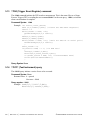
3-1.2
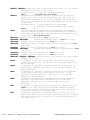
KEY FEATURES
A few of the most important features of Status Reporting are shown below.
Operation Complete - The IEEE-488.2 structure provides one technique that can be used to
find out if any operation is finished. The “OPC” command, when sent to
the instrument after the operation of interest, will set the OPC bit in the
Standard Event Status Register. If the OPC bit and the RQS bit have
been enabled, a service request will be generated.
Send(0,5,”*SRE;*ESE1",11,EOI);
Send(0,5,”*TRG;*OPC”,9,EOI);
!enables an OPC service request.
!initiates data acquisition.
!will generate a SRQ when the
!acquisition is complete.
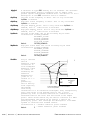
The Trigger Bit - The TRG bit indicates if the device has received a trigger. The TRG event
register will stay set after receiving a trigger until it is cleared by reading it
or using the *CLS command. If your application needs to detect multiple
triggers, the TRG event register must be cleared after each one.
Send(0,5,”*SRE1",6,EOI);
Send(0,5,”:TER?”,5,EOI);
Send(0,5,”*TRG”,4,EOI);
Wait SRQ(0,result);
!enables a trigger service request.
!the next trigger will generate an SRQ.
!queries the TRG event register, thus
!clearing it.
!the next trigger can now generate an
!SRQ.
Status Byte - If the device is requesting service (RQS set), and the controller serial polls the
device, the RQS bit is cleared. The MSS bit (read with *STB?) will not be cleared
by reading it. The status byte is not cleared when read, except for the RQS bit.
Serial Poll - The SIA-3000™ supports the IEEE-488.1 serial poll feature. When a serial poll
of the instrument is requested, the RQS bit is returned on bit 6 of the status byte.
Using Serial Poll - This example will show how to use the service request by conducting a
serial poll of all instruments on the bus. In this example, assume that there
are two instruments on the bus; a DTS at address 5 and a printer at address
1. These address assumptions are made throughout this manual, and it is
also assumed that we are operating on GPIB controller board address 0.
The program command for serial poll using IEEE-488.2 in “C” is
ReadStatusByte (0,5,result);. The address 005 is the address
of the SIA-3000 in this example. The command for checking the printer is
ReadStatusByte (0,1,result); because the address of that
instrument is 01 on bus address 0. This command reads the contents of the
GPIB Status Register into the variable called result. At that time bit 6 of the
variable result can be tested to see if it is set (bit 6=1).
12 | Section 3 | Common Commands and Status
©WAVECREST Corporation 2005
The serial poll operation can be conducted in the following manner.
1. Enable interrupts on the bus. This allows the controller to “see” the
SRQ line.
2. If the SRQ line is high (some instrument is requesting service) then
check the instrument at address 1 to see if bit 6 of its status register
is high.
3. Disable interrupts on the bus.
4. To check whether bit 6 of an instruments status register is high, use
the following command line:
If (result & 0x40){
then
}
5. If bit 6 of the instrument at address 1 is not high, then check the
instrument at address 5 to see if bit 6 of its status register is high.
6. As soon as the instrument with status bit 6 high is found, check the
rest of the status bits to determine what is required.
The ReadStatusByte (0,5,result); command causes much
more to happen on the bus than simply reading the register. This command
clears the bus, automatically addresses the talker and listener, sends SPE
(serial poll enable) and SPD (serial poll disable) bus commands, and reads
the data. For more information about serial poll, refer to your controller
manual, and programming language reference manuals.
After the serial poll is completed, the RQS bit in the SIA-3000 Status
Byte Register will be reset if it was set. Once a bit in the Status Byte
Register is set, it will remain set until the status is cleared with a *CLS
command, or the instrument is reset.
Parallel Poll - The SIA-3000 does not support the parallel poll feature.
3-2
*CLS (Clear Status) command
The *CLS (clear status) common command clears the Event Status Register, the Status Byte
Register, the trigger bit, the local bit and the error queue.
The Event Status Register is read by the *ESR? query. The Status Byte Register is read by the
*STB? command or a serial poll.
Command syntax- *CLS
Example: Send(0,5,”*CLS”,4,EOI);
Query Syntax- None
©WAVECREST Corporation 2005
Section 3 | Common Commands and Status |13
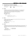
3-3
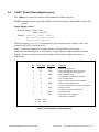
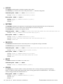
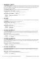
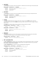
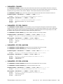
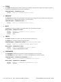
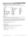
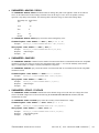
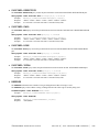
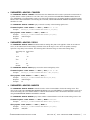
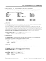
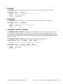
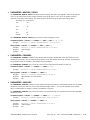
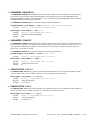
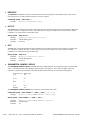
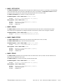
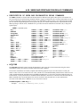
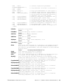
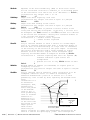
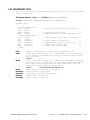
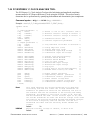
*ESE (Event Status Enable) command/query
The *ESE command sets the Standard Event Status Enable Register bits. The Standard Event
Status Enable Register contains a mask value for the bits to be enabled in the Standard Event
Status Register. A one (1) in the Standard Event Status Enable Register will enable the
corresponding bit in the Standard Event Status Register, a zero will disable the bit. Refer to
Table 3-1 for information about the Standard Event Status Enable Register bits, bit weights,
and what each bit masks.
The *ESE query returns the current contents of the register.
Command Syntax - *ESE <mask>
<mask>::=0 to 255
Example: Send(0,5,”*ESE 64",7,EOI);
In this example, the *ESE 64 command will enable URQ, user request, bit 6 of the Standard
Event Status Enable Register. Therefore, when a front-panel key is pressed, the event summary
bit (ESB) in the Status Byte Register will also be set.
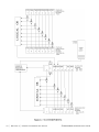
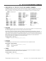
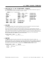
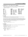
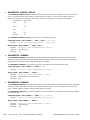
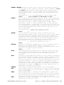
Event Status Enable Register
(High - Enables the ESR bit)
Bit
7
6
5
4
3
2
1
0
Weight
128
64
32
16
8
4
2
1
Enables
PON-Power On
URQ-User Request
CME-Command Error
EXE-Execution Error
DDE-Device Dependent Error
QYE-Query Error
RQC-Request Control
OPC-Operation Complete
Table 3-1 Standard Event Status Enable Register
Query Syntax - *ESE?
Returned Format: <mask><NL>
<mask>::=0 to 255
Example: Send(0,5,”*ESE?”,5,EOI);
Received(0,5,Event,1,EOI);
Printf(“%d\n”,Event);
14 | Section 3 | Common Commands and Status
©WAVECREST Corporation 2005
3-4
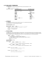
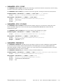
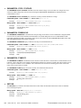
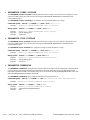
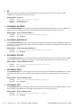
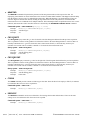
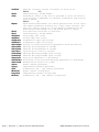
*ESR? (Event Status Register) query
This *ESR query returns the contents of the Standard Event Status Register.
NOTE: Reading the register clears the Standard Event Status Register and the ESB bit in the STB
register.
Query Syntax: *ESR?
Returned Format: <status><NL>
<status>::=0 to 255
Example: Send(0,5,”*ESR?”,5,EOI);
Receive(0,5,Event,1,EOI);
Printf(“%d\n”,Event);
With the example (*ESE=64), if a front-panel key has been pressed, the variable “event” will
contain 64, the URQ (User Request bit).
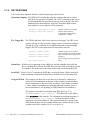
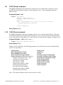
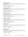
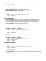
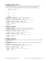
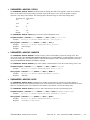
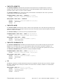
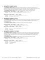
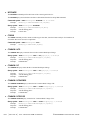
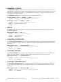
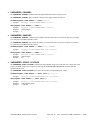
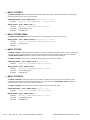
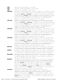
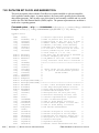
Table 3-2 shows the Standard Event Status Register. The table shows each bit in the
Standard Event Status Register as well as the bit weight. When you read Standard Event Status
Register, the value returned is the total bit weights of all bits that are high at the time you
read the byte.
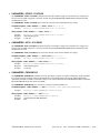
Event Status Register
Bit
Bit Weight
Bit Name
7
6
128
64
PON
URQ
5
32
CME
4
16
EXE
3
8
DDE
2
4
QYE
1
0
2
1
RQC
OPC
Condition
0=not used-always zero
0=no front panel key has been pressed
1=front panel key has been pressed
0=no command errors
1=a command error has been detected
0=no execution error
1=an execution error has been detected
0=no device dependent errors
1=a device dependent error has been detected
0-no query errors
1=a query error has been detected
0=request control
0=operation is not complete
1=operation is complete
0 = False = Low
1 = True = High
Table 3-2 Standard Event Status Register
©WAVECREST Corporation 2005
Section 3 | Common Commands and Status |15
3-5
*IDN? (Identification Number) query
The *IDN? query allows the instrument to identify itself. It returns the string:
“WAVECREST, SIA-3000, VERSION MAJOR, VERSION MINOR, REVISION LEVEL.”
VERSION MAJOR = Major version of software release.
VERSION MINOR = Minor version of software release.
REVISION LEVEL = Updates to current software release.
An *IDN? query must be the last query in a message. Any queries after the *IDN? in this
program message will be ignored.
Query Syntax- *IDN?
Returned Format: WAVECREST, SIA-3000, v NN.NN.NN
Example: CHAR MESSAGE[50];
Send(0,5,”*IDN?”,5,EOI);
Receive(0,5,MESSAGE,50,EOI);
Printf(“%s\n”,MESSAGE);
3-6
*OPC (Operation Complete) command/query
The *OPC (operation complete) command will cause the instrument to set the operation complete
bit in the Standard Event Status Register when all pending device operations have finished. The
*OPC? query places an ASCII “1” in the output queue when all pending device operations
have finished.
Command Syntax- *OPC
Example: Send(0,5,”*OPC”,4,EOI);
Query Syntax- *OPC?
Example: Send(0,5,”*OPC?”,5,EOI);
Receive(0,5,data,1,EOI);
Returned format: “1”
3-7
*OPT? (Options) query
The *OPT (options) query will return the current options, in text format, available/installed in
the SIA-3000.
Query Syntax- *OPT?
Example: Send(0,5,”*OPT?”,5,EOI);
Receive(0,5,data,1,EOI);
3-8
*RCL (Recall) command
The *RCL command restores the state of the SIA-3000 from a specified set of saved setups.
There can be ten (10) different setups (1 through 10).
Command Syntax- *RCL<specific setup>#
Example: Send(0,5,”*RCL1",6.EOI);
Query Syntax- None
NOTE: See common command *SAV for specific information recalled/saved.
16 | Section 3 | Common Commands and Status
©WAVECREST Corporation 2005
3-9
*RST (Reset) command
The *RST command place the instrument in a known state. The output buffer is cleared as well as
the ESR and serial poll status registers. Use the interface clear (IFC) bus command to perform a
hardware reset.
Command Syntax- *RST
Example: int result;
Send(0,5,”*CLS”,4,EOI);
Send(0,5,”*RST;*OPC”,9,EOI);
result=0
while ((result&0X20 !=0){ /*wait for reset to finish*/
ReadStatusByte(0,5,&result);
}
/*reset complete*/
Query Syntax- None
3-10 *SAV (Save) command
The *SAV command stores the current settings of the SIA-3000 in non-volatile memory. This setup
is saved and recalled by specifying a specific setup from 1 to 10. See the list below for the parameters
saved. Notice that for each setting (1-10), each of the ten (10) functions has a number of settings saved.
Command Syntax- *SAV<specific setup>#
Example: Send(0,5,”*SAV6”,5,EOI);
Query Syntax- None
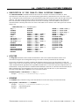
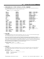
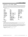
During a SAVE or RECALL, the following parameters are saved for later recall or recalled and used
as SIA-3000 parameters:
Arming Source
Filter maximum DC Channel
Filter minimum Strobe delay
Filter On/Off Strobe input channel
Function Selection (defines edge direction)
Channel selection (Ch1/Ch2/…/Chn)
Arming event arming sequence
Start reference voltage
Stop reference voltage
External Arm reference voltage
External Arm edge direction
Pulse find levels (percentages)
Start/Stop edge (rising or falling)
Start/Stop arm on nth count
Gating on/off
Sample size
Sets size
Start/Stop external arming inputs
Start/Stop VOH (max peak) voltage
Start/Stop VOL (min peak) voltage
Strobe arming channel
Strobe increment value
Strobe number of points
Strobe start point
Strobe stop point
Notes: The external calibration values are not saved on a SAVE.
©WAVECREST Corporation 2005
Section 3 | Common Commands and Status |17
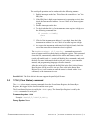
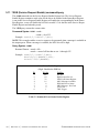
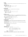
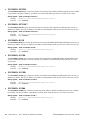
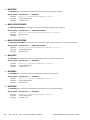
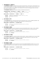
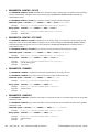
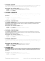
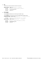
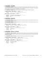
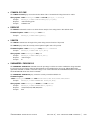
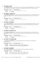
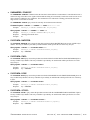
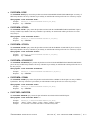
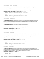
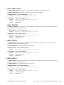
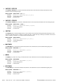
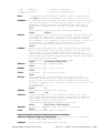
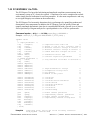
3-11 *SRE (Service Request Enable) command/query
The *SRE command sets the Service Request Enable Register bits. The Service Request
Enable Register contains a mask value for the bits to be enabled in the Status Byte Register.
A one in the Service Request Enable Register will enable the corresponding bit in the Status
Byte Register, a zero will disable the bit. Refer to table 3-3 for the bits in the Service Requst
Enable Register and what they mask.
The *SRE query returns the current value.
Command Syntax- *SRE <mask>
<mask>::=0 to 255
Example: Send(0,5,”*SRE16",7,EOI);
NOTE: This example enables a service request to be generated when a message is available in
the output queue. When a message is available, the MAV bit will be high.
Query Syntax- *SRE?
Returned Format: <mask><NL>
<mask>::=sum of all bits that are set - 0 through 255
Example: Send(0,5,”*SRE?”,5,EOI);
Receive(0,5,ENABLE,1,EOI);
Printf(“%d\n”,ENABLE);
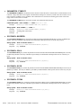
Event Status Enable Register
(High - Enables the ESR bit)
Bit
Weight
7
6
5
4
3
2
1
0
128
64
32
16
8
4
2
1
Enables
not used
RQS-Request Service
ESR-Event Status Register
MAV-Message Available
SDS-Sub-Device Status
MSG-Message - Not Used
LCL-Local
TRG-Trigger
Table 3-3 Standard Event Status Enable Register
18 | Section 3 | Common Commands and Status
©WAVECREST Corporation 2005
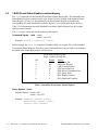
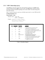
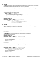
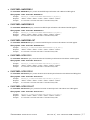
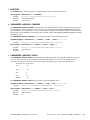
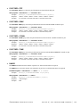
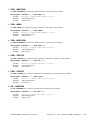
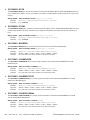
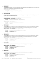
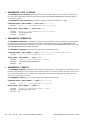
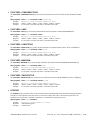
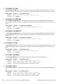
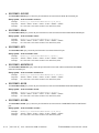
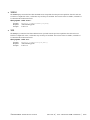
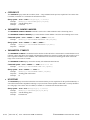
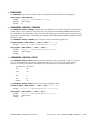
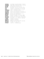
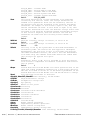
3-12 *STB? (Status Byte) query
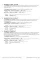
The *STB query returns the current value of the instrument’s status byte. The MSS (Master
Summary Status) bit and not RQS is reported on bit 6. The MSS indicates whether or not the
device has at least one reason for requesting service. Refer to table 3-4 for the meaning of the
bits in the status byte.
Note: To read the instrument’s status byte with RQS reported on bit 6, use the GPIB Serial Poll.
Command Syntax- None
Query Syntax- *STB?
Returned Format: <value><NL>
<value>::= 0 through 255
Example: Send(0,5,”*STB?”,5,EOI);
Receive(0,5,STATUS,1,EOI);
Printf(“%d\n”,STATUS);
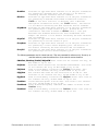
Bit
Bit Weight
Bit Name
Condition
------RQS/MSS
0=not used
0=instrument has no reason for service
1=instrument is requesting service
0=no event status conditions have occurred
1=an enabled event status condition has occurred
0=no output messages are ready
1=an output message is ready
0=special device status
0=no message has been displayed
1=message has been displayed
0=a remote to local transition has not occurred
1=a remote to local transition has occurred
0=no trigger has occurred
1=a trigger has occurred
7
6
128
64
5
32
ESR
4
16
MAV
3
2
8
4
SDS
MSG Not Used
1
2
LCL
0
1
TRG
Table 3-4 Status Byte Register
©WAVECREST Corporation 2005
Section 3 | Common Commands and Status |19
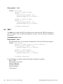
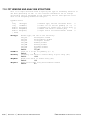
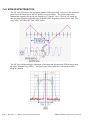
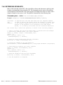
3-13 *TRG (Trigger Event Register) command
The *TRG command initiates the DTS to take a measurement. This is the same effect as a Group
Execute Trigger (GET) or sending the root command RUN. Use the root query, :TER?, to indicate
when a measurement is complete.
Command Syntax- *TRG
Example: int result, event_status;
Send (0,5,”:TER?”,5,EOI); /*clears the TRG Event Register*/
result = 0
while((result & 0x01) !=0){
ReadStatusByte(0,5,& result);
}
Send(0,5,”*CLS”,4,EOI);
Send(0,5,”*TRG”,4,EOI);
while((result & 0x01) !=1){ /*wait for TRG bit of serial poll*/
ReadStatusByte(0,5,& result);
}
event_status = 0;
if((result & ESB) = = 1) /*if ESB set*/
{
Send(0,5,”*ESR?”,5,EOI);
Receive(0,5,event_status,1,EOI);
if((event_status & DDE) !=0) /*if measurement bad*/
Printf(“failed measurement”);
}
Query Syntax- None
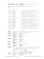
3-14 *TST? (Test Instrument) query
The *TST? query initiates a series of tests to be executed.
Command Syntax- None
Returned value: 0 = passed
Non-zero = failed
Query syntax- *TST?
Example: Send(0,5,”*TST?”,5,EOI);
Receive(0,5,status,1,EOI);
20 | Section 3 | Common Commands and Status
©WAVECREST Corporation 2005
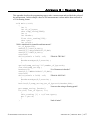
SECTION 4 – Root Commands
4-1
DESCRIPTION OF THE ROOT COMMANDS
The ROOT commands are used to do a few basic instrument functions or read status.
Root commands:
:LER?
:RUN
:SDS?
:TER?
4-2
LER?
The LER? query reads the Local Event Register. When the query is received and the register
is read, it is also cleared. The status of the Local Event Register (0 or 1) is indicated by a
serial poll status bit 1. When the LCL bit of a serial poll is a 1, the Device Clear (DCL) is
complete. See the common command *RST for use with the LER? query.
Command syntax - None
Query syntax - :LER?
Example: int result;
Send(0,5,”:LER?”,5,EOI);
ReadStatusByte(0,5,& result);
Printf(“%d\n”,result);
4-3
RUN
The RUN command initiates a measurement to be started in the SIA-3000. Performs the same
function as common command *TRG.
Command syntax - :RUN
Example: Send(0,5,”:RUN”,4,EOI);
Query syntax- None
4-4
SDS?
The SDS? query reads the Special Device Status register. When the query is received the register value
is returned and the register is cleared. The status of the Special Device Status register (0 or 1) is
indicated by a serial poll or STB command on bit 3. This bit is used differently by specific instrument
commands.
Recall storage...................1 = command complete
Display panel ON.............1 = command complete
Command syntax- None
©WAVECREST Corporation 2005
Section 4 | Root Commands | 21
Query syntax- :SDS?
Example: int result
Send(0,5,”:SDS?”,5,EOI);
result = 1;
while((result&0x08) !=0) {
ReadStatusByte(0,5,& result) ;
}
Send(0,5,”*RCL5”,5,EOI);
result = 0,
while((result&0x08 = =0) {
ReadStatusByte(0,5,& result);
}
/*command complete*/
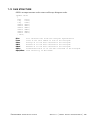
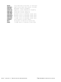
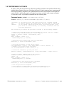
4-5
TER?
The TER? query enables the TRG Event Register to be read. Once the TRG Event Register is
read, it is cleared. A one (1) indicates a trigger has occurred. A zero (0) indicates a trigger has
not occurred.
Command syntax- None
Query syntax- :TER?
Returned Format: Bit 1 of a serial poll will indicate the value of the TRG Event Register.
Example: int result;
Send(0,5,”:TER?”,5,EOI); /*clear TRG bit*/
while((result & 0x01) !=0){
ReadStatusByte(0,5, & result);
}
Send(0,5,”*TRG”,4,EOI);
while((result & 0x01) !=1){
ReadStatusByte(0,5, & result);
}
/*command complete*/
Use the TER query to indicate when the following commands are complete:
Burst (*TRG)
Pulse Finder (:ACQ:LEV)
Internal Calibration
External Calibration
Strobe Calibration
Cable Measure
22 | Section 4 | Root Commands
©WAVECREST Corporation 2005
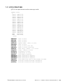
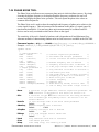
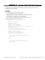
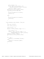
SECTION 5 – Basic Measures GPIB
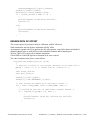
5-1
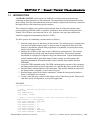
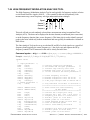
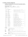
Introduction
Of the three GPIB command sets that can be implemented, Basic Measures is the “lowest” level. It provides essential
signal measurements such as Period/Pk-Pk/1-sigma and skew. It is also the fastest method and is used mostly in ATE or
production environments where very basic tests and fast test times are required. While this method is fast, it is not
comprehensive.
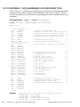
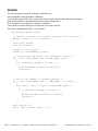
Example code
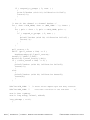
The following example is typical of a simple measurement of the period of a clock signal. It is pseudo code because
different operating systems and programming languages may have different requirements for some instructions. In
general, this example should serve as a useful example.
// Pseudo - code to set up a period measurement - assumes channel 1
Send(0,5,":ACQ:FUNC PER",13,EOI);
// Period measurement
Send(0,5,":ACQ:COUN 1000(@1)",18,EOI);
// Set the sample count
Send(0,5,":CHAN1START:COUNT 1",19,EOI);
// First rising edge
Send(0,5,":CHAN1STOP:COUNT 2",18,EOI);
// To next rising edge
Send(0,5,":TRIG:SOURCE INTERNAL",21,EOI); // Arm off the signal itself
Send(0,5,":DISP:LEV 5050",14,EOI);
// 50% voltage threshold
// Pseudo-code to sample the signal to establish the voltage threshold
// This takes about 130ms, otherwise user voltages can be used
Send(0,5,":ACQ:LEV(@1)?",13,EOI);
// Request the "pulsefind"
Receive(0,5,Buffer,sizeof(Buffer),EOI);
// Go get the results
// The buffer will hold results (min voltage, max voltage) similar to the following:
:ACQUIRE:LEVEL -0.1082758 +0.8043081
// To establish user voltages use the following:
Send(0,5,":DISP:LEV USER",14,EOI);
// USER voltage threshold
Send(0,5,":CHANSTART:LEV -0.125",21,EOI); // First measurement edge
Send(0,5,":CHANSTOP:LEV -0.125",20,EOI); // Next measurement edge
// To take the measurement use the following command
Send(0,5,":ACQ:ALL PER(@1)",16,EOI);
Receive(0,5,Buffer,sizeof(Buffer),EOI);
// Request the measurement
// Go get the results
// The buffer will hold results (avg, stdev, min, max) similar to the following:
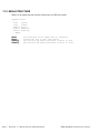
:ACQUIRE:ALL +1.1082758e-009 +2.8043081e-12 +1.1006245e-009 +1.1163601e-009
//For skew measurements similar commands are used, except substitute the following:
Send(0,5,":ACQ:FUNC TPD++",13,EOI);
// TPD from rising to rising edge
Send(0,5,":ACQ:COUN 1000(@1,2)",20,EOI); // Set the sample count, both channels
Send(0,5,":CHAN1START:COUNT 1",19,EOI);
// First rising edge, channel 1
Send(0,5,":CHAN2STOP:COUNT 1",18,EOI);
// First rising edge, channel 2
Send(0,5,":TRIG:SOURCE INTERNAL",21,EOI); // Arm off the signal itself
Send(0,5,":DISP:LEV 5050",14,EOI);
// 50% voltage threshold
// Pseudo-code to sample the signal to establish the voltage threshold
// This takes about 130ms, otherwise user voltages can be used
Send(0,5,":ACQ:LEV(@1,2)?",13,EOI);
// Request the "pulsefind", both channels
Receive(0,5,Buffer,sizeof(Buffer),EOI);
// Go get the results
// The buffer will hold results (min voltage, max voltage) similar to the following:
:ACQUIRE:LEVEL -0.1082758 +0.8043081 -0.1006245 +0.1163601
// To take the measurement use the following command
Send(0,5,":ACQ:ALL TPD++(@1&2)",16,EOI);
Receive(0,5,Buffer,sizeof(Buffer),EOI);
©WAVECREST Corporation 2005
// Measurement from Chan1 to Chan2
// Go get the results
Section 5 | Basic Measures Commands | 23
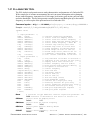
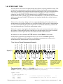
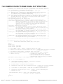
5-2
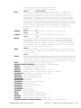
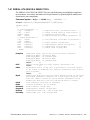
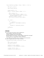
ACQUIRE COMMANDS
The ACQUIRE commands are used to set parameters used during a measure command.
:ACQuire:<command syntax>
Acquire commands:
ALL
ANALysis
COMPlete
COUNt
DUTY
FUNCtion
GROup
LEVel
MEASure
SETsCOUNt
TIMEOUT
RUN
WINDow
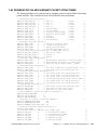
• ALL
The ALL command will select 1 of 11 functions, take a measurement and return the average, standard deviation, minimum
and maximum. The function selected will force the following parameters to defaults:
Edges - Rising or falling
Channel - Single or both (if a single channel function, start or stop will be selected based on last single channel selected).
Arming - Auto-on-start, auto-on-stop, start first or stop first, based on the last arming sequence selected for that function.
Command syntax- :ACQuire:ALL<TT+|TT-|PW+|PW-|PERiod+|PERiod-|TPD++|TPD- -|TPD+|TPD-+|FREQ>
Example: Send(0,5,”:ACQuire:ALLTT+”,15,EOI);
Receive(0,5,data,4,EOI);
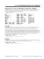
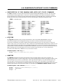
• ANALYSIS:CLOCK
The ANALYSISCLOCK command will run a preset macro to initiate and return four measurements of four functions (PW+,
PW-, Per+, Per-; Avg, Min, Max, standard deviation) for a total of 16 measurements based on the channel list selected.
Command syntax- :ACQuire:ANALysisCLOCk(@<n,m,x,...>|<n:m>)
Example: Send(0,5,”:ACQuire:ANALysisCLOCk200”,25,EOI);
Receive(0,5,data,4,EOI)
• ANALYSIS:FUNCTION
The ANALYSISFUNCTION command selects 1 of 10 functions and takes a measurement for the number of counts. The
returned values are the mean of the measure, standard deviation, minimum and maximum in binary for each event where event
is defined as a measurement. The returned values are in picoseconds except for frequency that returns the values in kilohertz.
Command syntax- :ACQuire:ANALysisFUNCtion</FUNC/LowStartCount/HighStartCount
/StopCountDesignator/Increment/DataDes>(@<n,m,x,…>|<n:m>)
Example: Send(0,5,”:ACQuire:ANALysisFUNCtion/PW+/1/1/100/=/10/4”,44,EOI);
Example: Send(0,5,”:ACQuire:ANALysisFUNCtion/PER/2/1/100/+/10/4”,44,EOI);
If StopCount Designator = “+”, Returns Stop Event
= “=”, Returns Start Event
If DataDes = 2
Returns: Mean and standard deviation in binary
If DataDes = 4
Returns: The mean, standard deviation, minimum and maximum in binary.
Default: DataDes = 4
24 | Section 5 | Basic Measures Commands
©WAVECREST Corporation 2005
• ANALYSIS:JITTER
The ANALYSISJITTER command selects 1 of 10 functions and takes a measurement for the number of counts. The
returned values are jitter, standard deviation, minimum and maximum in binary for each event where event is defined as
a measurement. The returned value is in picoseconds, except for frequency that returns the values in kilohertz.
Command syntax- ACQuire:ANALysisJITTer</FUNC/CHAN/StartCount/LowStopCount
/HighStopCount/Increment/DataDes>
Example: Send(0,5,”:ACQuire:ANALysisJITTer/PW+/1/1/1/100/10/3”,42,EOI);
Example: Send(0,5,”:ACQuire:ANALysisJITTer/PER/2/1/2/100/10/3”,42,EOI);
If DataDes = 3
Returns: Jitter, i.e., standard deviation, min, max in binary.
If DataDes = 2
Returns: Jitter, i.e., standard deviation and mean.
Default: DataDes = 3
•
ANALYSIS:RANGE
The ANALYSISRANGE command is similar to the ANALYSISJITTER command except the returned value is the range,
(Max –Min)/2, with minimum and maximum in binary for each event where event is defined as a measurement.
Command syntax- :ACQuire:ANALysisRANGe</FUNC/CHAN/StartCount/LowStopCount
/HighStopCount/Increment/DataDes>
Example: Send(0,5,”:ACQuire:ANALysisRANGe/PW+/1/1/1/100/10/3”,41,EOI);
Example: Send(0,5,”:ACQuire:ANALysisRANGe/PER/2/1/2/100/10/3”,41,EOI);
If DataDes = 3
Returns: Range, min, max in binary.
If DataDes = 2
Returns: Range, standard deviation and mean.
Default: DataDes = 3
•
COMPLETE
The COMPLETE query returns the number of measurements completed for the specified channels. The returned value will
be an ASCII integer value.
Command syntax- NONE
Query syntax- :ACQuire:COMPlete(@<n,m,x,…>|<n:m>)?
Example: Send(0,5,”:ACQuire:COMPlete?”,18,EOI);
Receive(0,5,data,1,EOI);
Response: <ASCII count>
•
COUNT
The COUNT command sets the number of measurements used to develop the statistics, average, minimum, maximum,
range and standard deviation for the specified channels. The number of measurements can range from 1 to 1,000,000.
The COUNT query returns the present setting of the count value.
Command syntax- :ACQuire:COUNt<ASCII integer value>(@<n,m,x,…>|<n:m>)
Example: Send(0,5,”:ACQuire:COUNt200",17,EOI);
Query syntax- :ACQuire:COUNt(@<n,m,x,…>|<n:m>)?
Example: Send(0,5":ACQuire:COUNt?”,15,EOI);
Receive(0,5,data,1,EOI);
Response: <ASCII integer>
©WAVECREST Corporation 2005
Section 5 | Basic Measures Commands | 25
• DUTY
The DUTY command will calculate the duty cycle of the signal and return a three digit ASCII number. The percent will
be of the positive pulse width in a format of xx.x%.
Command syntax- :ACQuire:DUTY(@ <n,m,x,…>|<n:m>)
Example: Send(0,5,”:ACQuire:DUTY”,12,EOI);
Response: 49.8 (49.8%)
• FUNCTION
The FUNCTION command will select 1 of 11 functions that will guide the instrument during time measurements. The
function selected will force the follow parameters to defaults:
Edges - Rising or falling
Channel - Single or both (if a single channel function, start or stop will be selected
based on last single channel selected).
Arming - Auto-on-start, auto-on-stop, start first or stop first, based on the last arming
sequence selected for that function.
The FUNCTION query will return the currently selected function.
Command syntax- :ACQuire:FUNCtion<TT+|TT-|PW+|PW-|PERiod+|PERiod-|TPD++|TPD- |TPD+-|TPD-+|FREQ>
Example: Send(0,5,”ACQuire:FUNCtionTT+”,19,EOI);
Query syntax- :ACQuire:FUNCtion?
Example: Send(0,5,”:ACQuire:FUNCtion?”,18,EOI);
Response: <TT+|TT-|PW+|PW-|PER|TPD++|TPD—|TPD+-|TPD-+|FREQ>
• GROUP
After a user has defined a group (see Section 5-11, :SYSTem:GROUP<ON|OFF>), this command is called to execute
all the commands that had been queued up in that particular group.
Command syntax- :ACQuire:GROUP<1-20>
Example: Send(0,5,”:ACQuire:GROUP5”, 17, EOI);
• LEVEL
The LEVEL command causes the instrument to find the pulse levels on the start and/or stop channels depending on the
channel selection. If the arming source selected is external, the levels of the arming channels are found as selected.
The levels are stored and can later be read by using the channel commands. The percent of the peak level found will be
displayed and returned as the new start and stop references.
The levels found for each channel are the minimum and maximum peak and the selected percentage of these peaks.
Command syntax- :ACQuire:LEVel(@ <n,m,x,…>|<n:m>)
Example: Send(0,5,”:ACQuire:LEVel@”,14,EOI);
Query syntax- :ACQuire:LEVel(@ <n,m,x,…>|<n:m>)?
26 | Section 5 | Basic Measures Commands
©WAVECREST Corporation 2005
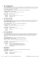
• MEASURE
The MEASURE command will take a time measurement and return the average and standard deviation. The present
function and reference voltages are used. This is a fast method of performing the acquire run command repetitively.
Command syntax- :ACQuire:MEASure
Example: Send(0,5,”:ACQuire:MEASure”,16,EOI);
Receive(0,5,data,2,EOI);
• RUN
The RUN command will select 1 of 10 functions, take a measurement and return the average and standard deviation. The
function selected will force the following parameters to defaults:
Edges - Rising or falling
Channel - Single or both (if a single channel function, start or stop will be selected
based on last single channel selected.
Arming - Auto-on-start, auto-on-stop, start first or stop first, based on the last arming
sequence selected for that function.
Command syntax- :ACQuire:RUN<TT+|TT-|PW+|PW-|PERiod+|PERiod-|TPD++|TPD- -|TPD+|TPD- +|FREQ>(@<n,m,x,…>|<n:m>)
Example: Send(0,5,”:ACQuire:RUNTT+”,15,EOI);
Receive(0,5,data,1,EOI);
• SETSCOUNT
The SETSCOUNT command sets the count of a set of measurements that will create an average. This average is used with
other set averages of sample size, to create the statistics available for return over the GPIB interface. The sets size value can
range from 1 to 950000.
As an example, a sets size of a 100 and sample size of 1000 means that the statistics are of 10000
measurements of size 100.
The SETSCOUNT query returns the present setting of the sets size.
Command syntax- :ACQuire:SETsCOUNt<1 to 950000>(@ <n,m,x,…>|<n:m>)
Example: Send(0,5,”:ACQuire:SETsCOUNt100",21,EOI);
Query syntax- :ACQuire:SETsCOUNt(@ <n,m,x,…>|<n:m>)?
Example: Send(0,5,”:ACQuire:SETsCOUNt?”,19,EOI);
Response: <ASCII setscount>
©WAVECREST Corporation 2005
Section 5 | Basic Measures Commands | 27
• TIMEOUT
The TIMEOUT command configures the maximum time that is allowed for a measurement set as a whole to be
completed. The :SYSTEM:TIMEOUT command is used to set the timeout for one individual measurement, regardless of
the sample size. Even if the :SYSTEM:TIMEOUT command is set to a sufficient value, the measurement may fail due to
a large sample size, intermittent arming, or in the event of an :ACQUIRE:ANALYSIS command which may span a
range of start and stop counts. The :ACQUIRE:TIMEOUT command is used to set a maximum timeout for the
measurement set as a whole, the allowable values are from 1 to 10,000 seconds, and the default is 16 seconds.
Command syntax- :ACQuire:TIMEOUT<1 to 10000>
Example: Send(0,5,”:ACQuire:TIMEOUT100”,19,EOI);
Query syntax- :ACQuire:TIMEOUT?
Example: Send(0,5,”:ACQuire:TIMEOUT?”,17,EOI);
Response: 16
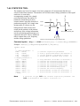
• WINDOW
The WINDOW command is a macro to set parameters and return the average (mean) voltage of the window. The window
can be of a delay from 20,000ps to 100,000,000ps.
To describe a window, three (3) parameters can be given. If any parameter is omitted the forward slash (/) must be
placed in the command to indicate the proper spacing.
The three parameters are:
start delay value .............................................20,000ps to 100,000,000ps
stop delay value .............................................20,000ps to 100,000,000ps
increment between points ..............................see system strobe increment command
or
number of measurement points......................see system strobe points command
Command syntax- :ACQuire:WINDow/start value/stop value/<step increment|#of points>
Example 1: Send(0,5,”:ACQuire:WINDow/25000/50000/1000”,32,EOI);
Receive(0,5,voltage level,5,EOI);
Example 2: Send(0,5,”:ACQuire:WINDow/25000/50000/#100”,32,EOI);
Receive(0,5,voltage level,5,EOI);
28 | Section 5 | Basic Measures Commands
©WAVECREST Corporation 2005
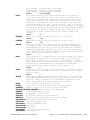
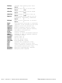
5-3
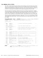
CALIBRATE COMMANDS
The CALIBRATE commands enables the host to perform an internal or external calibration and set or read the external
calibration values.
:CALibrate:<command syntax>
Calibrate commands:
DATA
DESKEW
DESKEWDC
INTernal
SIGnal
STATus
XINTernal
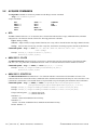
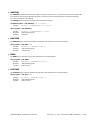
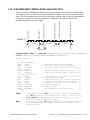
• DATA
The DATA command can be used to enable the host to write the individual channel skew values to the instrument.
There are 10 skew values (one value per possible SIA channel) that must be sent to the device from the host in the
following format (ANSI/IEEE Std. 754-1985 floating-point standard):
#xy..dddddddddd.., where:
x = an ASCII digit representing the number of digits in y
y = a string of digits, of x length, which represents the number of bytes of information to be sent.
d = calibration data
The DATA query command is used to read the 10 values that are returned in the same floating-point format (ANSI/IEEE
Std. 754-1985).
Command Syntax- :CALibrate:DATA<#xy..dddddddddd..>
Example: Send(0,5, “:CALibrate:DATA#280<80 bytes of data
(10 skew values - 10x8)>”, 99, EOI);
Query Syntax- :CALibrate:DATA?
Example: Send(0,5, “:CALibrate:DATA?”, 20, EOI);
Response: #280<80 bytes of data(10 skew values - 10x8)>
• DESKEW
The DESKEW command permits the user to perform the Deskew calibration remotely over GPIB rather than on the SIA3000 front panel (GigaView™).
Command syntax- :CALibrate:DESKEW
Example: Send(0,5,”:CALibrate:DESKEW”,17,EOI);
• DESKEWDC
The DESKEWDC command permits the user to perform the Deskew with DC calibration remotely over GPIB rather than
using the SIA3000TM front panel (GigaView).
Command syntax- :CALibrate:DESKEWDC
Example: Send(0,5,”:CALibrate:DESKEWDC”,19,EOI);
• INTERNAL
The INTERNAL command permits the user to perform the internal (Timer) calibration remotely over GPIB rather than
using the SIA3000 front panel (GigaView). The internal calibration function will process 20,000,000 samples while
taking 11 minutes to complete.
Command syntax- :CALibrate:INTernal
Example: Send(0,5,”:CALibrate:INTernal”,19,EOI);
See Appendix A for a more complete example.
©WAVECREST Corporation 2005
Section 5 | Basic Measures Commands | 29
• XINTERNAL
The EXTENDED INTERNAL CALIBRATION allows the user to possibly reduce jitter due to the noise floor of the
instrument through the use of longer internal calibration periods. The multiplier, from 1 to 25, extends the base
calibration period of approximately 5.5 minutes by the selected multiplier. A setting of 6 is recommended.
Command Syntax- :CALibrate:XINTernal<ASCII VALUE>
Example: Send(0,5,“:CALibrate:XINTernal6”,21,EOI”);
• SIGNAL
The SIGNAL command will set the calibration signal to the specified parameter.
Command Syntax- :CALibrate:SIGnal<OFF|10M|900MOUTP|900INP>
Example: Send(0,5,”:CALibrate:SIGnal1M”,19,EOI);
Query syntax- :CALibrate:SIGnal?
Example: Send(0,5,”:CALibrate:SIGnal?”,18,EOI);
Response: 10M
• STATUS
The STATus query will return the current status of the calibration tests. (0 = pass, 1 = fail):
Command Syntax- None
Query syntax- :CALibrate:STATUS?
Example: Send(0,5,”:CALibrate:STATUS?”,15,EOI);
Bit Pos.
0
1
3
4
Hex Value
1
2
4
8
Description
Internal Calibration
Deskew Calibration
DeskewDC Calibration
Strobe Calibration
30 | Section 5 | Basic Measures Commands
©WAVECREST Corporation 2005
5-4
CDR COMMANDS
The CDR commands are used to do a few basic instrument functions or to read the instrument status.
:CDR:<command syntax>
CDR commands:
CORRection
COUNT
LOCKED
RATE
In all of the following commands the "n" in (@n) should be replaced with the channel number of the CDR. The
numbering for the CDR's begins at 1 more than the number of measurement channels in the system. For example, if
there are 5 measurement channels in the system, the first CDR would be specified (@6).
• CORRECTION
The CORRECTION command enables/disables the voltage correction for a particular CDR.
Note: The voltage correction is only applied to oscilloscope measurements on the measurement channel associated
with the CDR.
The CORRECTION query determines if the channel voltage correction is enabled.
Returns:
0 if disabled,
1 if enabled
-1 if an error was encountered.
Command syntax - :CDR:CORRection<ON|OFF|1|0>(@n)
Example:
Send(0,5,”:CDR:CORRectionON@3",19,EOI);
Query syntax - :CDR:CORRection(@n)?
Example:
Response:
Example:
Send(0,5,”:CDR:CORRection@3?”,18,EOI);
<-1|0|1>
1
• COUNT?
The COUNT query determines the number of CDRs in the system.
Returns: 0,1,2,3,4,or 5 on success
-1 if an error was encountered
Command syntax - None
Query syntax - :CDR:COUNT?
Example: Send(0,5,”:CDR:COUNT?”,11,EOI);
Response: <-1|0|1|2|3|4|5>
Example: 2
• LOCKED?
The LOCKED query determines the lock state of a specified CDR.
Returns: 0 if locked or
-29 if unlocked; an error was encountered
Command syntax- NONE
Query syntax- :CDR:LOCKED(@n)?
Example: Send(0,5,”:CDR:LOCKED@3?”,14,EOI);
Response: <-29|0>
Example: 0
©WAVECREST Corporation 2005
Section 5 | Basic Measures Commands | 31
• RATE
The RATE command sets the current bit rate for a specified CDR.
NOTE: The bit rate specified should be in the range 25e6 - 3.18e9 bits/sec.
The RATE query determines the current bit rate setting for a specified CDR.
Returns: A bit rate in the range 25e6 - 3.18e9 bits/sec.
-1 if an error was encountered
Command syntax - :CDR:RATE><bit rate>(@n)
Example: Send(0,5,”:CDR:RATE2.500e9@3",18,EOI);
Query syntax - :CDR:RATE(@n)?
Example: Send(0,5,”:CDR:RATE@3?”,18,EOI);
Response: <25e6 - 3.18e9 bits/sec>
Example: 2500000000.000000
32 | Section 5 | Basic Measures Commands
©WAVECREST Corporation 2005
5-5
CHANNEL COMMANDS
The CHANNEL commands write and read the channel start and stop reference voltages, the arm-on-nth counts and external
arming selections. Multiple DSMs can be configured using the SWITCH command Mux address (@n) from 1 to 8.
:CHANnel<n><STARt|STOP>:<command syntax>
Channel commands:
COUNt
EXTernalarm
FREQuency
LEVel
MINimum/MAXimum
SWITch
• COUNT
The COUNT command sets the arm-on-nth-event count for either the start or stop event. The range of the nth event is from
1 to 10000000.
The COUNT query returns the count of either the start or stop event.
Command syntax- :CHANnel<n><STARt|STOP>:COUNt<value>
Example: Send(0,5,”:CHANnel4STARt:COUNt100",23,EOI);
Query syntax- :CHANnel<n><STARt|STOP>:COUNt?
Example: Send(0,5,”:CHANnel4STOP:COUNt?”,20,EOI);
Response: <ASCII count>
• EXTERNALARM
The EXTERNALARM command selects which arming channel is associated with the start and stop events.
The EXTERNALARM query returns the arming selected for a specific (start/stop) event.
Command syntax- :CHANnel<n>:EXTernalarm<a>
Example: Send(0,5,”:CHANnel4:EXTernalarmARM1",25,EOI);
Query syntax- :CHANnel<n>:EXTernalarm?
Example: Send(0,5,”:CHANnel4:EXTernalarm?”,22,EOI);
Response: <ARM1|ARM2>
• LEVEL
The LEVEL command sets the start/stop reference levels. The range is ±2 volts in 150-microvolt resolution.
The LEVEL query returns the start/stop levels. The level returned is an integer value.
Command syntax- :CHANnel<n><STARt|STOP>:LEVel<value>
Example: Send(0,5,”:CHANnel4STARt:LEVel+1.5",24,EOI);
Query syntax- :CHANnel<n>STARt:LEVel?
Example: Send(0,5,”:CHANnel4STARt:LEVel?”,21,EOI);
Response: <value>
Example: +1.50000
See Appendix C for more information regarding returned data formats.
©WAVECREST Corporation 2005
Section 5 | Basic Measures Commands | 33
• MINIMUM/MAXIMUM
The MINIMUM/MAXIMUM query returns the minimum or maximum peak levels of the start or stop reference levels.
The peak values measured when the last pulse find was initiated. This pulsefind could have been initiated from the
front panel or with the :Acquire:Level command.
Command syntax- None
Query syntax- :CHANnel<n><STARt|STOP>:<MIN|MAX>?
Example: Send(0,5,”:CHANnel4STARt:MIN?”,19,EOI);
Response: <ASCII MIN or MAX peak level>
Example: -1.01890
• SWITCH ON/OFF
The SWITCH ON/OFF command enables or disables the switches on the front panel of the DSM-16.
Command syntax- :CHANnel:SWITch(@n)<ON|OFF>
Example: Send(0,5,”:CHANnel:SWITch4ON”,17,EOI);
Query syntax- NONE
• SWITCH IDN
The SWITCH IDN query returns the version number of the DSM–16. The returned value is an ASCII number
representing the version major and minor (i.e. 1.1).
Command syntax- None
Query syntax- :CHANnel:SWITch(@n)IDN?
Example: Send(0,5,”:CHANnel:SWITch4IDN?”,19,EOI);
Response: <ASCII number 1-8>
• SWITCH number
The SWITCH number command identifies the instrument’s input channel to be selected. The DSM–16 was designed to be
used as a 1 of 8 matrix to the instrument’s channel (1 of 8 to channel X, and 1 of 8 to channel Y). The matrix inputs are
assigned channel numbers 11-18 and 21-28.
NOTE: A small number of units are labeled 1 through 16.
Command syntax- :CHANnel:SWITch(@n)<11...18|21...28>
Example: Send(0,5,”:CHANnel:SWITch215",17,EOI);
This will select the left bank of eight, fifth input from the left of the DSM with Mux address 2.
NOTE: The DSM-16 can be configured as a 1 of 15 matrix by connecting the eighth input from the left bank to the
Channel 2 output.
Query syntax- :CHANnel:SWITch(@n)?
Example: Send(0,5,”:CHANnel:SWITch2?”,16,EOI);
Response: <ASCII digits>
The returned format is ASCII digits representing the Mux address of the DSM, followed by both channel and switch
numbers and separated by a space.
Example: 2 2 3
34 | Section 5 | Basic Measures Commands
©WAVECREST Corporation 2005
5-6
DISPLAY COMMANDS
The DISPLAY commands control the displaying of information on the front panel and if filtering is used in developing the
statistics.
:DISPlay:<command syntax>
Display commands:
FILTer – ON/OFF/0/1
MIN/MAX (Limits)
LEVel
USER
• FILTER (ON/OFF)
The FILTER (ON/OFF) command is used to select whether filtering will be used in calculating the statistics.
The FILTER query returns the current ON|OFF|0|1 selection.
Command syntax- :DISPlay:FILTer<ON|OFF>
Example: Send(0,5,”:DISPlay:FILTerON”,17,EOI);
Query syntax- :DISPlay:FILTer?
Example: Send(0,5,”:DISPlay:FILTer?”,16,EOI);
Response: <ON|OFF>
• FILTER (Limits)
The FILTER (limits) query commands return the ASCII floating point value of the presently set limits. Limits are ±2.5
seconds. Maximum setting must be greater than Minimum setting. A value of -999,999,999 is returned by the measure
deviation query command if there were not any measurements within the limits.
Command syntax- :DISPlay:FILTer<MINimum|MAXimum><signed ASCII floating point>
Example: Send(0,5,”:DISPlay:FILTerMINimum+0.000000000500",37,EOI);
Query syntax- :DISPlay:FILTer<MINimum|MAXimum>?
Example: Send(0,5,”:DISPlay:FILTerMINimum?”,23,EOI);
Response: <Signed ASCII floating point>
Example: -5.000000e+001 (-0.5)
• LEVEL
The LEVEL command sets the start and stop percentage level of peaks that the start and stop references will be set to.
This percentage of peak will also be what the front panel start and stop references will be displaying.
The LEVEL query will return a start and stop percentage setting in two ASCII integers.
Command syntax- :DISPlay:LEVel<5050|1090|9010|2080|8020>
Example: Send(0,5,”:DISPlay:LEVel2080",18,EOI);
Query syntax- :DISPlay:LEVel?
Example: Send(0,5,”:DISPlay:LEVel?”,15,EOI);
Response: <valuevalue>
Example: 2080
©WAVECREST Corporation 2005
Section 5 | Basic Measures Commands | 35
• USER
The USER command selects the user set of references of the current function.
The instrument is capable of having the reference voltages set by two (2) methods.
1. Doing a pulse find and setting the references to a percentage of the peaks found.
2. Setting the start and stop voltage trip reference to a value.
When the user set the reference voltages directly, this is defined as a USER setting and is later selected by the display
user command.
The USER query returns the setting of the user reference voltages.
Command syntax- :DISPlay:USER<ON|OFF|0|1>
Example: Send(0,5,”:DISPlay:USERON”,15,EOI);
Query syntax- :DISPlay:USER?
Example: Send(0,5,”:DISPlay:USER?”,14,EOI);
Response: <ON|OFF|0|1>
36 | Section 5 | Basic Measures Commands
©WAVECREST Corporation 2005
5-7
FILE COMMANDS
The FILE commands are used to transfer files to and from the SIA3000 using the GPIB interface.
:FILE:<command syntax>
File commands:
APPEND
LIST
READ
SAVE
• APPEND
The APPEND command is used to upload files from a host computer to the SIA3000. The GPIB input buffer is of limited
size; so large files must be uploaded in chunks. The first block should be written using the :FILE:SAVE command,
then subsequent blocks should be sent using the :FILE:APPEND command. Individual chunks should be no larger than
10,000 bytes in size. An ASCII header that specifies the size of the data in bytes precedes the data chunk.
Command syntax- :FILE:APPEND<filename><#xyy…ddddddd…>
Example: Send(0,5,":FILE:APPEND K285.PTN#280…",105,EOI);
• LIST
The LIST command is used to obtain a tab delimited list of the files present in a directory on the SIA3000. Folders
within the directory requested are returned with their names enclosed in brackets.
Command syntax- :FILE:LIST<directory>
Example: Send(0,5,":FILE:LIST C:",18,EOI);
Response: <ASCII string><tab><ASCII string>…
Example: [Drivers] [Temp] [Visi] [WinNT] autoexec.bat boot.ini config.sys
• READ
The READ command is used to download a file from the SIA3000 to the host computer. An ASCII header that specifies
the size of the data in bytes precedes the data chunk.
Command syntax- :FILE:READ<filename>
Example: Send(0,5,":FILE:READ K285.PTN",19,EOI);
Response: #xy…dddddddd…
• SAVE
The SAVE command is used to upload files from a host computer to the SIA3000. The GPIB input buffer is of limited
size; so large files must be uploaded in chunks. The first block should be written using the :FILE:SAVE command,
then subsequent blocks should be sent using the :FILE:APPEND command. Individual chunks should be no larger than
10,000 bytes in size. The data chunk is preceded by an ASCII header which specifies the size of the data in bytes. If the
target files already exists, the file will be truncated to zero length before the data chuck is written to it.
Command syntax- :FILE:SAVE<filename><#xyy…ddddddd…>
Example: Send(0,5,":FILE:SAVE K285.PTN#280…",103,EOI)
©WAVECREST Corporation 2005
Section 5 | Basic Measures Commands | 37
5-8
GLOBAL COMMANDS
The GLOBAL commands are used to set some parameters which are global across all tools.
:GLOBAL:<command syntax>
Global commands:
CHANnel<N>:ATTENuation
RISEFALL
• CHANNEL:ATTENUATION
The CHANNEL:ATTENUATION command is used to scale the scope output to compensate for scope probes, or some
other external scaling factor. This scaling factor is applied before any analysis is performed on the scope data. The
amount of attenuation can be specified by a multiplier or in dB’s.
The CHANNEL:ATTENUATION query returns the current scope output scaling factor.
Command syntax- :GLOBal:CHANnel<N>:ATTENuation<-40 to 40>DB
Example: Send(0,5,":GLOB:CHAN4:ATTEN 3DB",21,EOI);
Command syntax- :GLOBal:CHANnel<N>:ATTENuation<0.01 to 100>X
Example: Send(0,5,":GLOB:CHAN4:ATTEN 0.01X",24,EOI);
Query syntax- :GLOBal:CHANnel<N>:ATTENuation?
Example: Send(0,5,":GLOB:CHAN4:ATTEN?",18,EOI);
Response: <ASCII floating point>dB/<ASCII floating point>X
Example: 0.000dB/1.000X
• RISEFALL
The RISEFALL command is used to specify the voltage thresholds for calculating Rise Time and Fall Time. The input
can either be in percentage or in absolute voltage. If specified in percentage, it is assumed to be symmetrical about the
50% threshold, so the second term is effectively ignored. Both terms are respected if the value is entered in absolute
voltage.
The RISEFALL query returns the current voltage thresholds for calculating Rise Time and Fall Time.
Command syntax- GLOBal:RISEFALL<1 to 49>/<51 to 99>
Example: Send(0,5,":GLOB:RISEFALL 10/90",20,EOI);
Command syntax- GLOBal:RISEFALL<-2000 to 2000>MV/<-2000 to 2000>MV
Example: Send(0,5,":GLOB:RISEFALL -200MV/200MV",27,EOI);
Query syntax- GLOBal:RISEFALL?
Example: Send(0,5,":GLOB:RISEFALL?",15,EOI);
Response: <ASCII integer>/<ASCII integer>
Example: 10/90
-ORResponse: <ASCII integer>mV/<ASCII integer>mV
Example: -150mV/250mV
38 | Section 5 | Basic Measures Commands
©WAVECREST Corporation 2005
5-9
MARKER COMMANDS
The MARKER<n> commands are used to configure the pattern marker and read basic pattern marker statistics.
:MARKER<n>:<command syntax>
MARKER commands:
BEC?
EDGEcount
MODE
OUTput
PATTern
PROTocol
RESET
STATus
In all of the following commands, the "n" in <n> should be replaced with the channel number of the pattern marker.
• BEC?
The BEC? query returns the specified pattern marker’s bit error count when the SIA-3000 is in pattern match mode.
Query syntax - :MARKer<n>:BEC?
Example: Send(0,5,”:MARKER1:BEC?”,13,EOI);
Response: <ASCII strings>
Example: (FrameNo1) (ExpBits1) (ErrBits1) (LoopCnt1)
(FrameNo2) (ExpBits2) (ErrBits2) (LoopCnt2)
…
(FrameNo63) (ExpBits63) (ErrBits63) (LoopCnt63)
(FrameNo64) (ExpBits64) (ErrBits64) (LoopCnt64)
• EDGECOUNT
The EDGECOUNT command sets the count of rising or falling edges.
The EDGECOUNT query returns the current count of rising or falling edges.
Command syntax - :MARKer<n>:EDGEcount<2-2147483647>
Example: Send(0,5,”:MARKer2:EDGEcount6”,19,EOI);
Query syntax - :MARKer<n>:EDGEcount?
Example: Send(0,5,”:MARKer2:EDGEcount?”,19,EOI);
Response: <2-2147483647>
Example: 6
• MODE
The MODE command selects the pattern marker measurement mode. Select either Pattern Match or Edge Count. In Pattern
Match mode, the pattern marker card will generate a Pattern Marker when matching a unique 40-bit sequence of a pattern. The
PROTOCOL also needs to be selected accordingly. In Edge Count mode, the pattern marker card will generate a pattern marker
upon repetition of a user-specified number of positive or negative edges. For PRBS patterns use Edge Count mode only.
The MODE query returns the currently selected mode.
Command syntax - :MARKer<n>:MODE<EDGEcount|PATTernmatch>
Example: Send(0,5,”:MARKer3:MODEEDGE",17,EOI);
Query syntax - :MARKer<n>:MODE?
Example: Send(0,5,”:MARKer3:MODE?”,14,EOI);
Response: <EDGEcount|PATTernmatch>
Example: EDGE
©WAVECREST Corporation 2005
Section 5 | Basic Measures Commands | 39
• OUTPUT
The OUTPUT command enables or disables the pattern marker output.
The OUTPUT query returns the current state of the pattern marker. (1=Selected, 0=Bypassed)
Command syntax - :MARKer<n>:OUTPut<SELect|BYPass>
Example: Send(0,5,”:MARKer3:OUTPutSEL",18,EOI);
Query syntax - :MARKer<n>OUTPut?
Example: Send(0,5,”:MARKer3:OUTPut?”,16,EOI);
Response: <0|1>
Example: 1
• PATTERN
The PATTERN command sets the pattern that is matched against when Pattern Match Mode is selected. The pattern is
also used as the master reference to detect errors when the Bit Error Counter is being used.
The PATTERN query returns the current pattern selected.
Command syntax - :MARKer<n>:PATTern<CJTPAT.PTN|CLOCK.PTN|CRPAT.PTN|IDLE.PTN|K285.PTN|etc…>
Example: Send(0,5,”:MARKer3:PATTernCLOCK.PTN",25,EOI);
Query syntax - :MARKer<n>:PATTern?
Example: Send(0,5,”:MARKer3:PATTern?”,17,EOI);
Response: <CJTPAT.PTN|CLOCK.PTN|CRPAT.PTN|IDLE.PTN|K285.PTN|etc…>
Example: CLOCK.PTN
• PROTOCOL
The PROTOCOL command selects the measurement protocol. Not applicable for Edge Count Mode.
The PROTOCOL query returns the current protocol selected.
Command syntax - :MARKer<n>:PROTocol<FC1X|GB1X|SATA|FC2X|GB2X|SATA2|XAUI|FC3X>
Example: Send(0,5,”:MARKer2:PROTocolFC1X”,21,EOI);
Query syntax - :MARKer<n>:PROTocol?
Example: Send(0,5,”:MARKer2:PROTocol?”,18,EOI);
Response: <FC1X|GB1X|SATA|FC2X|GB2X|SATA2|XAUI|FC3X>
Example: FC1X
• RESET
The RESET command resets the BEC error count to zero.
Command syntax - :MARKer<n>:RESET
Example: Send(0,5,”:MARKER1:RESET”,14,EOI);
• STATUS
The STATUS query returns the whether or not the pattern marker card is currently detecting a signal and outputting a
marker. If a signal is currently being detected and a marker is being generated, this command returns a 1. If no marker is
currently being generated, this command returns a 0.
Query syntax - :MARKer<n>:STATus?
Example: Send(0,5,”:MARKER1:STATus?”,13,EOI);
Response: <0|1>
Example: 1
40 | Section 5 | Basic Measures Commands
©WAVECREST Corporation 2005
5-10 MEASURE COMMANDS
The MEASURE query returns the measurement statistics from the instrument to a host.
:MEASure:<command syntax>
MEASURE commands:
Time Measurement
AVERage
DATA (Float or Double)
DATA4
DATAT
EVENt
JITTer
MAXimum
MINimum
RANGe
Standard DEViation
STAT4
XDATA
DC Measurement
Single DClevel
NOTDCvlevel
STRObeVLEVel
Multiple VDATA
VDATA4
VMAXimum
VMINimum
VSDEViation
WINDow
• AVERAGE
The AVERAGE command returns the measured average of 1 to 1,000,000 measurements.
The returned value is an ASCII floating point number.
Command syntax- None
Query syntax- :MEASure:AVERage(@ <n,m,x,…>|<n:m>)?
Example: Send(0,5,”:MEASure:AVERage?”,17,EOI);
Response: <ASCII floating point>
Example: -8.4566284e-011
• DATA/DATA4
The DATA query returns a selected number of measured values. These measured data values can be analyzed or used to
provide a presentation. The Measure Data query supports two sizes of data types (See Appendix C) using IEEE standards
for floating-point arithmetic (ANSI/IEEE Std. 754-1985). The returned data stream is of the following format:
:MEASure:DATAT<xy...dddddddd...>
x = an ASCII digit representing the number of digits in y
y = a string of digits, of x length, which represents the number of bytes of
information to be returned.
d=data
Command syntax- None
Query syntaxFloat :MEASure:DATA4(@ <n,m,x,…>|<n:m>)?
:MEASure:Data#43200<200 bytes of data (50 measurements – 50x4)>
Double :MEASure:DATA(@ <n,m,x,…>|<n:m>)?
:MEASure:Data#3400<400 bytes of data (50 measurements – 50x8)>
Example: char data[2048]
Send(0,5,:MEASure:DATA4?,15,EOI);
Receive(0,5,data,205,EOI);
Example: char data[2048]
Send(0,5,:MEASure:DATA?,14,EOI);
Receive(0,5,data,405,EOI);
©WAVECREST Corporation 2005
Section 5 | Basic Measures Commands | 41
• DATAT
The DATAT query command returns the elapsed time measurements from a previous burst after the elapsed time
counter has been turned on. With a sample size of 100 there will be 100 floating-point time measurements returned.
The DATAT query returns a selected number of measured values. These measured data values can be analyzed or used
to provide a presentation. See Appendix C for the returned data stream format types:
:MEASure:DATAT<xy...dddddddd...>
x = an ASCII digit representing the number of digits in y
y = a string of digits, of x length, which represents the number of bytes of
information to be returned.
d=data
Query syntax- :MEASure:DATAT(@ <n,m,x,…>|<n:m>)?
Float :MEASure:DATAT?
Example: char data[2048]
Send(0,5,”:MEASure:DATAT?”,15,EOI);
Receive(0,5,data,205,EOI);
• DCVLEVEL
The DCVLEVEL command returns the dc voltage measured on the selected input channel. The returned value is an
ASCII string of five digits preceded by a (+) or (-) sign. The value is a signed integer with 100 microvolt resolution.
Command syntax- :MEASure:DCvlevel(@ <n,m,x,…>|<n:m>)?
Example: Send(0,5,”:MEASure:DCvlevel?”,18,EOI);
Response: -1.1444092e-004
• JITTER
The JITTER query returns the standard deviation of the selected sample size.
Command syntax- None
Query syntax- :MEASure:JITTer(@ <n,m,x,…>|<n:m>)?
Example: Send(0,5,”:MEASure:JITTer?”,16,EOI);
Response: <ASCII floating point>
Example: +7.3441603e-012
• MAX
The MAX query command returns the maximum measured value of a set of measurements.
Command syntax- None
Query syntax- :MEASure:MAX(@ <n,m,x,…>|<n:m>)?
Example: Send(0,5,”:MEASure:MAX?”,13,EOI);
Response: <ASCII floating point>
Example: -6.5307617e-011
• MIN
The MIN query command returns the minimum measured value of a set of measurements.
Command syntax- None
Query syntax- :MEASure:MIN(@ <n,m,x,…>|<n:m>)?
Example: Send(0,5,”:MEASure:MIN?”,13,EOI);
Response: <ASCII floating point>
Example: -1.1169434e-010
42 | Section 5 | Basic Measures Commands
©WAVECREST Corporation 2005
• RANGE
The RANGE query command returns the plus or minus difference between the maximum and minimum values of a set of
measurements.
Command syntax- None
Query syntax- :MEASure:RANGe(@ <n,m,x,…>|<n:m>)?
Example: Send(0,5,”:MEASure:RANGe?”,15,EOI);
Response: <ASCII floating point>
• SDEVIATION
The SDEVIATION query returns the standard deviation of the selected sample size.
Command syntax- None
Query syntax- :MEASure:SDEViation(@ <n,m,x,…>|<n:m>)?
Example: Send(0,5,”:MEASure:SDEViation?”,20,EOI);
Response: <ASCII floating point>
Example: +7.3441603e-012
• STAT(istics)4
The STAT4 query returns statistical data defined by :SYST:STAT for multiple SETS of measurements as float. The
:SYST:STAT/ON command must be executed prior to using the STAT4 command. Statistics are always returned in the
order of AV, JI, MN and MX, depending on which ones are selected.
Command syntax- :MEASure:STAT4(@ <n,m,x,…>|<n:m>)?
Example: Send(0,5,”:MEASure:STAT4?”,15,EOI);
Response: <4-Byte float (Intel)>
Example: <ON|OFF><AV><JI><MN><MX>
• STROBEVLEVEL
The STROBEVLEVEL query returns the strobed dc voltage measured on the input channel selected. The strobing is
provided through the arming channel. The strobing arm point can be be controlled by the strobe delay or by external
moving the arming signal.
The returned value is an ASCII string of five (5) digits preceded by a (+) or (-) sign. The value is a signed integer with
100 microvolt resolution.
To perform a strobed measurement, set up the following parameters:
STRObe CHANnel
STRObe ARMing
STRObe DELay
Command syntax- None
Query syntax- :MEASure:STRObeVLEVel(@ <n,m,x,…>|<n:m>)?
Example:
Send(0,5,”:SYSTem:STRObeCHANnel1”,22,EOI);
Send(0,5,”:SYSTem:STRObeARMARM1”,21,EOI);
Send(0,5,”:SYSTem:STRObeDELay25000”,24,EOI);
Send(0,5,”:MEASure:STRObeVLEVel?”,21,EOI);
Receive(0,5,voltage level,5,EOI);
Response:
Example:
<ASCII floating point>
-2.1731481e-003
To perform multiple measurements that are averaged, see the :MEASure:WINDow command.
©WAVECREST Corporation 2005
Section 5 | Basic Measures Commands | 43
• VDATA
The VDATA query returns the voltage measurement points acquired in the previous measure window or acquire window
command. The measured data values can be analyzed or used to provide a presentation.
Each voltage value is returned in 5 digits preceded by a (+) or (-) sign. The returned voltage is an ASCII integer string of
100 microvolt resolution.
Example: +0.0001 (+100 uv) would be +1
-1.0 (-1 v) would be -1000
The returned data stream is of the following format:
:MEASure:VDATA<xy...dddddddd...>
x = an ASCII digit representing the number of digits in y
y = an ASCII string of digits, of x length, which represents the number of bytes of
information to be returned.
d=data
Command syntax- None
Query syntax- :MEASure:VDATA(@ <n,m,x,…>|<n:m>)?
Example:
char data [2048];
Send(0,5,”:MEASure:VDATA?”,15,EOI);
Receive(0,5,data,60,EOI);
• VDATA4
The VDATA4 query is the same as the VDATA command except that the data is returned as float for throughput. (See
VDATA, Section 10-14.) See Appendix C for returned formats.
Command syntax- None
Query syntax- :MEASure:VDATA4(@ <n,m,x,…>|<n:m>)?
Example: Send(0,5,”:MEASure:VDATA4?”,16,EOI);
• VMAXIMUM
The VMAXIMUM query returns the maximum voltage value measured in the previous measure
window or acquire window command.
Command syntax- None
Query syntax- :MEASure:VMAXimum(@ <n,m,x,…>|<n:m>)?
Example: Send(0,5,”:MEASure:VMAXimum?”,18,EOI);
Receive(0,5,voltage level,5, EOI);
Response: <Signed ASCII value>
Example: -0.00758
• VMINIMUM
The VMINIMUM query returns the minimum voltage value measured in the previous measure
window or acquire window command.
Command syntax- None
Query syntax- :MEASure:VMINimum(@ <n,m,x,…>|<n:m>)?
Example: Send(0,5,”:MEASure:VMINimum?”,18,EOI);
Receive(0,5,voltage level,5,EOI);
Response: <Signed ASCII value>
Example: -0.00821
44 | Section 5 | Basic Measures Commands
©WAVECREST Corporation 2005
• VSDEVIATION
The VSDEVIATION query returns the voltage standard deviation of the previous measure window
or acquire window command. The returned value is a 6-digit ASCII string of a decimal number.
Command syntax- None
Query syntax- :MEASure:VSDEViation(@ <n,m,x,…>|<n:m>)?
Example: char data [10];
Send(0,5,”:MEASure:VSDEViation?”,21,EOI);
Receive(0,5,data,7,EOI);
Response: <Signed ASCII value>
• WINDOW
The WINDOW query instructs the instrument to take a series of strobed voltage measurements
and then returns the average (mean) voltage. The following statistics are also available upon
completion of the command.
VMAXIMUM ........................................Maximum voltage measured
VMINIMUM..........................................Minimum voltage measured
VSDEVIATION.....................................Standard deviation of voltages measured
The following parameters must be set up prior to sending a measure window query:
CHANnel ..............................................................................Select channel to be strobed
ARMing channel ..............................................................Select strobing (arming) input
STARting point delay ................................................Set delay for the first strobed point
STOPping point delay ............................................ Set delay for the last strobed point
INCRement between points ................................... Set increment between strobed points.
(the instrument will calculate the number
of points between start and stop)
MEASure WINdow? ...................................................................... Takes measurements and returns average
STRObe
STRObe
STRObe
STRObe
STRObe
NOTE: Strobe increment defines a delay between each measurement. The instrument determines how many points to
measure. An alternate method is to define the number of points between the first and last delayed points
(:SYSTem:STRObe#) and the instrument will determine the delay increment between measured points.
Example: Send(0,5,”:SYSTem:STRObeCHANnel1”,22,EOI);
Send(0,5,”:SYSTem:STRObeARMARM1”,21,EOI);
Send(0,5,”:SYSTem:STRObeSTArt25000”,24,EOI);
Send(0,5,”:SYSTem:STRObeSTOP50000”,23,EOI);
Send(0,5,”:SYSTem:STRObeINCRememt1000”,27,EOI);
Send(0,5,”:MEASure:WINdow?”,16,EOI);
Receive(0,5,voltage level,6,EOI);
To measure a single strobe point, see the STROBEVLEVEL command.
To use a macro type of command to set up delays, take the measurements and return the
voltage average, see the :ACQuire:WINdow command.
Command syntax- None
Query syntax- :MEASure:WINDow(@ <n,m,x,…>|<n:m>)?
Example: Send(0,5,”:MEASure:WINDow?”,16,EOI);
Receive(0,5,data,5,EOI);
Response: <Signed ASCII value>
Example: -0.00758
©WAVECREST Corporation 2005
Section 5 | Basic Measures Commands | 45
5-11 SYSTEM COMMANDS
The SYSTEM commands control the way channels are selected, messages are formatted, front panel keys are simulated
and how voltage measurement will be taken.
:SYSTem:<command syntax>
ADDRess
GO
ARMing
GROup
BWE
HEADer
CHANnel
INPUTS
COMPatible
LOCKEDPLL
DCCHANnel
LONGform
ELAPsed
MACro
ENDian
MINimum
FLAG
NOGO
GATing
REFERence
RESET
SKIPCNT
STATistics
STRObeARM
STRObeCAL
STROBeCHANnel
STRObeDELay
STRObeINCRement
STRObeMINimum
STRObeSTARt
STRObeSTEPs
STRObeSTOP
TEST
TEMPerature
TIMeout
WAVe
WAIT
WINDow
• ADDRESS
The ADDRESS command permits the user to change the address assigned to the SIA-3000 when it is communicating
over GPIB. For example, the default address for the SIA-3000 is 5, but a user may have already connected an
oscilloscope to his/her test system that has the same address. The user could then change the address of the SIA-3000 to
any number between 0 and 30 (except 5!) so that a host computer could communicate to both the 3000 and the
oscilloscope at the same time.
NOTE: Once the user changes the GPIB address of the SIA-3000 using :SYST:ADDRess, they need to follow the call
with a system reset (:SYSTem:RESET) command in order for the change to take effect. (See :SYSTem:RESET
command.)
Command syntax - :SYSTem:ADDRess<0-30>
Example: Send(0,5,”:SYSTem:ADDRess5”,16,EOI);
Query syntax- :SYSTem:ADDRess?
• ARMING
The ARMING command is a macro command to allow the sending of all commands related to arming the instrument in
one command.
The parameters that can be sent are:
Trigger source..............................................................EXTernal/AUTomatic
Trigger sequence..........................................................STARt/STOP
Arming channel input ..................................................<a>
Arming reference.........................................................±1.1
Arming slope (edge) ....................................................RISe/FALl
Start arm on count........................................................1 to 131072
Stop arm on count........................................................1 to 131072
The parameter’s position is defined by a forward slash (/). If a parameter is not being set the forward slash must be used.
Command syntax - :SYSTem:ARMing/trigger source/trigger sequence/arming channel<a>/
arming ref/arming slope/start count/stop count
Example 1: Send(0,5,”:SYSTem:ARMing/EXT/STAR/2/+0.0001/RIS/2/256”,43,EOI);
The following example only sets the arming reference voltage and slope.
Example 2: Send(0,5,”:SYSTem:ARMing/ / / /+0/FAL/ /”,26,EOI);
46 | Section 5 | Basic Measures Commands
©WAVECREST Corporation 2005
• BWE
The BWE command enables the bandwidth extension option. When enabled this will apply a DSP algorithm to all
oscilloscope measurements, which increases the apparent bandwidth of the front end (see the SIA-3000 User Manual
for additional information.)
Command syntax - :SYSTem:BWE<ON|OFF>
Example: Send(0,5,”:SYSTem:BWE ON”,14,EOI);
Query syntax - :SYSTem:BWE?
• CHANNEL
The CHANNEL command selects the input channel that will be measured.
The CHANNEL query returns the presently selected channel.
Command syntax - :SYSTem:CHANnel<n>
Example: Send(0,5,”:SYSTem:CHANnel1",16,EOI);
Query syntax - :SYSTem:CHANnel?
Example: Send(0,5,”:SYSTem:CHANnel?”,16,EOI);
Response: <1-10>
• COMPATIBLE
The COMPATIBLE command permits the operator to use the DTS Compatible set of GPIB commands when the
:SYSTem:COMPatible ON command is sent. If the operator wants to switch and use the new SIA-3000 GPIB
command set, the operator would send the :SYSTem:COMPatible OFF command.
Command syntax - :SYSTem:COMPatible<ON|OFF>
Example: Send(0,5,”:SYSTem:COMPatible ON”,21,EOI);
Query syntax - :SYSTem:COMPatible?
• DCCHANNEL
The DCCHANNEL command selects a DC measurement and the input channel that will be measured.
The DCCHANNEL query returns the channel presently selected.
Command syntax - :SYSTem:DCCHANnel<n>
Example: Send(0,5,”:SYSTem:DCCHANnel1",18,EOI);
Query syntax - :SYSTem:DCCHANnel?
Example: Send(0,5,”:SYSTem:DCCHANnel?”,18,EOI);
Response: <1-10>
• ELAPSED
The ELAPSED command enables the elapsed time counter to be initialized and it will be started
when the proper edge gate is received on the designated ARM channel input(s).
Command syntax- :SYSTem:ELAPsed<OFF|ON>(@<n,m,x,…>|<n:m>)
Example:
Send(0,5”:SYSTem:ELAPsedON”,16,EOI);
Query syntax- :SYSTem:ELAPsed?
Example:
Response:
Send(0,5,”:SYSTem:ELAPsed?”,15,EOI);
<”ON”|”OFF”>
©WAVECREST Corporation 2005
Section 5 | Basic Measures Commands | 47
• ENDIAN
The ENDIAN command is only applicable for operators who use UNIX to communicate with the SIA-3000 over GPIB.
In UNIX systems, numerical data is packaged the opposite of Windows 98 (which the SIA-3000 uses). In order for
UNIX users to receive numerica ldata in a format they can understand, “byte-swapping” of the data must be performed.
If the user sends the :SYSTem:ENDian BIG command, the SIA-3000 will perform “byte-swapping” on all
numerical data before sending it back to the user. To return to regular data packaging, the user would send the
:SYSTem:ENDian LITtle command.
Command syntax- :SYSTem:ENDian<BIG|LITtle>
Example: Send(0,5”:SYSTem:ENDian BIG”,17,EOI);
Query syntax- :SYSTem:ENDian?
Example: Send(0,5”:SYSTem:ENDian?”,17,EOI);
Response: <BIG|LITTLE>
• FLAG
The FLAG command allows the system flag to be set indicating some special purpose options are in effect. The value of
the flag is determined by adding together the following values:
1 - Enable Time Stamping
2 – Enable Adjacent Cycle Measurement
16 – Use Pattern Marker for External Arm
64 – Disable parallel timer measurements
128 – Timer select by Stop Channel
The FLAG query returns the current setting of the system flag.
Command syntax- :SYSTem:FLAG<0-255>
Example: Send(0,5,”:SYSTem:FLAG 16”,15,EOI);
Query syntax- :SYSTem:FLAG?
Example: Send(0,5,”:SYSTem:FLAG?”,13,EOI);
Response: <ASCII integer>
Response: 16
• GATING
The GATING command turns gating mode on or off. The selection of gating excludes the use of
the current ARM input. When gating is selected, the current ARM edge and reference voltage is associated with gating.
The GATING query returns the present setting of gating.
Command syntax- :SYSTem:GATing<ON|OFF>
Example: Send(0,5,”:SYSTem:GATingON”,16,EOI);
Query syntax- :SYSTem:GATing?
Example: Send(0,5,”:SYSTem:GATing?”,15,EOI);
Response: <ON|OFF>
• GO
The GO command simulates the user responding to a request for input from the SIA-3000 front panel. This command
would be used in conjunction with two (2) status bits of the Event Status Register (*ESR?). The host would look for the
event status register bit 1, Request Control (asking for the GO key to be pressed). The host would then send the system
go command and wait for the event status register bit 6, User Request, to be set to a one (1) indicating the simulated
response from the user was completed.
Command syntax- :SYSTem:GO
Example: Send(0,5,”:SYSTem:GO”,10,EOI);
48 | Section 5 | Basic Measures Commands
©WAVECREST Corporation 2005
• GROUP
The GROUP command permits the user to place the SIA-3000 in GROUP mode (:SYSTem:GROUP ON). When the
SIA-3000 is in GROUP mode, any GPIB commands it receives are recorded but not executed (no measurements are
made). When the user turns GROUP mode OFF and sends the :ACQuire:GROUP<n> command, all the commands
that where recorded earlier are executed automatically without any additional input required from the user. The
advantage to this method is that the user can instruct the instrument to perform a series of lengthy and complicated
measurements before the measurements are actually made, then simply wait for the data at the end. This results in a
shorter execution time then if the user asked for the first measurement, waited for the measurement to finish, retrieve the
data, ask for the second measurement, wait, etc., etc.
Command syntax - :SYSTem:GROup<1-20><ON|OFF>
Example: Send(0,5,”:SYSTem:GROUP ON”,15,EOI);
• HEADER
The HEADER command allow the option of not having the header returned on a response from the instrument.
The HEADER query returns the type of header presently selected.
Command syntax- :SYSTem:HEADer<OFF|ON>
Example: Send(0,5,”:SYSTem:HEADerOFF”,17,EOI);
Query syntax- :SYSTem:HEADer?
Example: Send(0,5,”:SYSTem:HEADer?”,15,EOI);
Response: <”0”|”1”> (OFF or ON)
•
INPUTS
The INPUTS query returns the number of input channel cards detected in the system.
Query syntax- :SYSTem:INPUTS?
Example: Send(0,5,”:SYSTem:INPUTS?”,15,EOI);
Response: <ASCII integer>
Example: 6
• LOCKEDPLL
The LOCKEDPLL query returns a 1 if the internal reference PLL is locked, or a 0 if it is not locked.
Query syntax- :SYSTem:LOCKEDPLL?
Example: Send(0,5,”:SYSTem:LOCKEDPLL?”,18,EOI);
Response: <0|1>
Example: 1
• LONGFORM
The LONGFORM command selects whether a header is returned from the instrument is of a long form or short form. This
command works with the HEADER command.
The LONGFORM query returns the presently selected long or short form.
Command syntax- :SYSTem:LONGform<OFF|ON>
Example: Send(0,5,”:SYSTem:LONGformOFF”,19,EOI);
Query syntax- :SYSTem:LONGform?
Example: Send(0,5,”:SYSTem:LONGform?”,17,EOI);
©WAVECREST Corporation 2005
Section 5 | Basic Measures Commands | 49
• MACRO
The MACRO command can be used to send multiple commands for a few settings that usually change frequently.
The parameters that can be sent are:
Function...................................................... TPD++/TPD—/TPD+-/TPD-+/TT+/TT-/PW+/PW-/PER/FREQ
Trigger Source ........................................... EXT/AUT
Arming Enable Sequence .......................... STAR/STOP
Peak Percentage........................................ 50 50/80 20/20 80/90 10/10 90
Note: Any combination greater than zero (0) and less than 100 is valid over the GPIB interface.
Start Input Voltage Reference.................... ±1.1
Stop Input Voltage Reference.................... ±1.1
Start Count ................................................. 1 to 131072
Stop Count ................................................. 1 to 131072
Command syntax- :SYSTem:MACro/Function/Trigger source/Trigger sequence
/percent/start reference voltage/stop reference voltage/start count
/stop count
Example: Send(0,5,”:SYSTem:MACro/TT+/AUT/STOP/80 20/+0.003/-0.001/2/256",51,EOI);
If a parameter is not used, that location can be left blank.
Example: Send(0,5,”:SYST:MAC/TPD++/ / / / / / /”,25,EOI);
• NOGO
The NOGO command simulates a user response to skip an operation after a request for input from the front panel. This
command would be used in conjunction of two (2) status bits of the Event Status Register (*ESR?).
The host would look for the event status register bit 1, Request Control (asking for the GO key to be pressed). The host
would then send the system nogo command and wait for the event status register bit 6, User Request to be set to a one (1)
indicating the simulated pressing of the go key was completed.
Command syntax- :SYSTem:NOGO
Example: Send(0,5,”:SYSTem:NOGO”,12,EOI);
• REFERENCE
The REFERENCE command selects whether the internal 10MHz reference signal is used, or an externally supplied
reference signal for the timebase.
The REFERENCE query returns whether an internal or external reference signal is being used for the timebase.
Command syntax- :SYSTem:REFerence<EXTernal|INTernal>
Example: Send(0,5,”:SYSTem:REFerence INTernal”,19,EOI);
Query syntax- :SYSTem:REFerence?
Example: Send(0,5,”:SYSTem:REFerence?”,17,EOI);
Response: <EXTERNAL>|<INTERNAL>
• RESET
The RESET command reboots GigaView; GigaView closes and restarts again automatically. This also happens when the user
presses the HW Reset button in the GigaView Configuration screen.
Command syntax- :SYSTem:RESET
Example: Send(0,5,”:SYST:RESET”,11,EOI);
50 | Section 5 | Basic Measures Commands
©WAVECREST Corporation 2005
• STAT
The STAT command saves a selected group of statistics for each measurement: Average, Jitter, Minimum and Maximum
for the desired number of channels.
The STAT query returns the selected group of statistics in ASCII form in the same order every time regardless of what
order they were selected. The order is AV, JI, MN, MX.
Command syntax- :SYSTem:STAT/<ON|OFF>/<AV><JI><MN><MX>(@<n,m,x,…>|<n:m>)
Example: Send(0,5,”:SYST:STAT/ON/JIAVMXMN”,22,EOI);
Query syntax- :SYSTem:STAT(@ <n,m,x,…>|<n:m>)?
Example: Send(0,5,”:SYST:STAT?”,11,EOI);
Response: <ON|OFF><AV><JI><MN><MX>
• STROBEARM
The STROBEARM command selects how a voltage measurement is taken. and selects the signal and edge controlling a
strobed voltage measurement. The strobed point on a waveform can be controlled by moving the strobe signal, when not
using the signal being strobed, or use the STROBEDELAY command.
If the strobe arm is not selected, the default “DC measurement without strobing” is used.
The STROBEARM query returns the strobe arm selected or DC if strobing is not selected.
Command syntax- :SYSTem:STRObeARM<n><RISe|FALl>
Example: Send(0,5,”:SYSTem:STRObe3RISe",19,EOI);
Query syntax- :SYSTem:STRObeARM<n>?
Example: Send(0,5,”:SYSTem:STRObe3?”,16,EOI);
Response: <n>
• STROBECAL
The STRObeCAL command initiates an Oscilloscope Strobe calibration.
Command syntax- :SYSTem:STRObeCAL
Example: Send(0,5,”:SYSTem:STRObeCAL”,17,EOI);
• STROBECHANNEL
The STROBECHANNEL command selects which input channel waveform will be strobed.
The STROBECHANNEL query returns the presently selected strobe channel.
Command syntax- :SYSTem:STRObeCHANnel<n>
Example: Send(0,5,”:SYSTem:STRObeCHANnel1",22,EOI);
Query syntax- ::SYSTem:STRObeCHANnel<n>?
Example: Send(0,5,”:SYSTem:STRObeCHANnel?”,22,EOI);
©WAVECREST Corporation 2005
Section 5 | Basic Measures Commands | 51
• STROBEDELAY
The STRObeDELay command is used to allow strobed voltage measurements along the pulses of a selected channel.
Strobing is armed from External Arm.
With the same signal on a selected channel and on the selected arm channel, the strobed voltage value read will be 20ns
from the beginning of the signal.
NOTE: To strobe at the beginning of a signal, delay the signal 20ns.
The STRObeDELay query returns the present strobe delay setting.
The range of delay settings is from 20,000ps to 100,000,000ps.
Command syntax- :SYSTem:STRObeDELay<value>(@<n,m,x,…>|<n:m>)
Example: Send(0,5,”:SYSTem:STRObeDELay20000",14,EOI);
Query syntax- :SYSTem:STRObeDELay(@<n,m,x,…>|<n:m>)?
Example: Send(0,5,”:SYSTem:STRObeDELay?”,13,EOI);
• STROBEINCREMENT
The STROBEINCREMENT command sets the increment between strobe points. The increment is set in picoseconds.
The STROBEINCREMENT query returns the present strobe delay increment.
NOTE: For any given delay, resolution at that delay is better than 0.2% of the delay.
Command syntax- :SYSTem:STRObeINCrement<value>(@<n,m,x,…>|<n:m>)
Example: Send(0,5,”:SYSTemSTRObeINCrement10000”,27,EOI);
Query syntax- :SYSTem:STRObeINCrement(@<n,m,x,…>|<n:m>)?
Example: Send(0,5,”:SYSTem:STRObeINCrement?”,24,EOI);
• STROBEMINIMUM
The STROBEMINIMUM query returns the minimum start delay for the measure window command. The delay is returned
in units of picoseconds.
Query syntax- :SYSTem:STRObeMINimum?
Example: Send(0,5,”:SYSTem:STRObeMINimum?”,22,EOI);
Response: <ASCII integer>
Example: 24000
• STROBESTART
The STROBESTART command sets the start delay for the measure window command. The delay can be from 20,000ps
to 100,000,000ps.
The STROBESTART query returns the present window start delay.
Command syntax- :SYSTem:STRObeSTARt<value>(@<n,m,x,…>|<n:m>)
Example: Send(0,5,”SYSTem:STRObeSTARt20000”,25,EOI);
Query syntax- :SYSTem:STRObeSTARt(@<n,m,x,…>|<n:m>)?
Example: Send(0,5,”:SYSTem:STRObeSTARt?”,20,EOI);
• STROBESTEPS
The STRObeSTEPs command sets the number of voltage measurement steps. The first measurement will be at the start
value. The STRObeSTEPs query will return the present window number of steps value.
Command syntax- :SYSTem:STRObeSTEPs<value>(@<n,m,x,…>|<n:m>)
Example: Send(0,5,”:SYSTem:STRObeSTEPs20”,17,EOI);
Query syntax- :SYSTem:STRObeSTEPs(@<n,m,x,…>|<n:m>)?
Example: Send(0,5,”:SYSTem:STRObeSTEPs?”,16,EOI);
Response: <ASCII integer>
52 | Section 5 | Basic Measures Commands
©WAVECREST Corporation 2005
• STROBESTOP
The STROBESTOP command sets the stop delay for the measure window command. The delay can be from 20,000ps to
100,000,000ps.
The STROBESTOP query returns the present window start delay.
Command syntax- :SYSTem:STRObeSTOP<value>(@<n,m,x,…>|<n:m>)
Example: Send(0,5,”:SYSTem:STRObeSTOP100000”,24,EOI);
Query syntax- :SYSTem:STRObeSTOP(@<n,m,x,…>|<n:m>)?
Example: Send(0,5,”:SYSTem:STRObeSTOP?,19,EOI);
•
TEMPERATURE
The TEMPERATURE query returns the temperature of the system in degrees Celsius.
Query syntax - :SYSTem:TEMPerature?
Example: Send(0,5,”:SYSTem:TEMPerature?”,21,EOI);
Response: <Signed ASCII value>
Example: +2.600e+001
• TIMEOUT
The TIMEOUT command sets the timeout value, in seconds, to wait before reporting “No Pulses Found”, during a
measurement.
The default, which is set at power up, is 10 seconds (floating point value).
Command syntax- :SYSTem:TIMeout<value>
Example: Send(0,5,”:SYSTem:TIMeout15”,17,EOI);
Query syntax- :SYSTem:TIMeout?
Example: Send(0,5,”:SYSTem:TIMe?”,13,EOI);
•
WAIT
The WAIT command allows a pause to occur in the midst of a series of acquisitions in order to provide a means for
synchronizing the measurements with some external action such as switching a mux or resetting a device. Whenever
the WAIT command is read in the GPIB command queue, the SDS bit in the ESR register is immediately set to
high. By conducting a status poll and monitoring this bit, the host controller can detect when the SIA3000 has
encountered the WAIT command, and is ready for the mux switching or other external activity to take place.
Once the SDS bit has been set to high, the SIA3000 system will wait the time that is specified in the WAIT
command. This time is specified in milliseconds, and a value from 10 to 100,000 is acceptable. This time should be
set long enough for the host controller to recognize that the SDS bit has gone high, complete it’s external action, and
wait for any settle time to occur.
If even faster response times are desired, the latency can be reduced through additional handshaking of the GPIB
bus. Once the SDS bit has been set high, the SIA3000 will also begin looking for a TRIGGER event. (The
TRIGGER event can be generated by using the ibtrg() command for National Instruments GPIB cards and
libraries, or by using the itrigger() command for HPIB cards and SICL libraries.)
If a TRIGGER event is detected prior to the wait time having expired, the SIA3000 will set the SDS bit back to low
once more. Once the host system has detected the SDS bit going low through continued status polling, it should
send a second TRIGGER event to acknowledge that the wait period should be terminated. Once the second
TRIGGER event is detected by the SIA3000, it will abort waiting and continue processing the next command in the
GPIB input buffer. Using this method the total handshaking time can be reduced to less than one millisecond.
©WAVECREST Corporation 2005
Section 5 | Basic Measures Commands | 53
Command syntax - :SYSTem:WAIT<10 to 100000>
Example: Send(0,5,”:ACQ:ALLPER;:SYST:WAIT10;:ACQ:ALLPER”,36,EOI);
status = 0;
while ((status & 0x08) == 0)
//Wait for the SDS bit to go high
ReadStatusByte(0, 5, &status);
SendTrigger();
//Acknowledge the SDS bit having gone high
ChangeMuxSetting();
//Perform our external activity
while (status & 0x08)
//Wait for the SDS bit to go low
ReadStatusByte(0, 5, &status);
SendTrigger();
//Acknowledge the SDS bit having gone low
• WAVE
The WAVE command selects the mode of pulsefind. Use FLAT to locate the flatspot of a square wave and use PEAK to
find the peaks of a sine waveform.
The WAVE query returns the presently selected mode.
Command syntax- :SYSTem:WAVe<PEAK|FLAT|STRObe>
Example: Send(0,5,”:SYSTem:WAVePEAK”,16,EOI);
Query syntax- :SYSTem:WAVe?
Example: Send(0,5,”:SYSTem:WAVe?”,13,EOI);
NOTE: Use the :ACQuire:LEVel(@ <n,m,x,…>|<n:m>)command to perform the pulsefind.
• WINDOW
The WINDOW command is a macro command to allow the parameter setup for the measure window command. A
window can be from 20ns to100µs given in picoseconds.
To describe a window three (3) parameters must be given, window start delay, window stop delay and either the measure
point increment or the number of points to make a measurement.
To set the parameters and return an average voltage measurement of the window, see the acquire window command.
Command syntax- :SYSTem:WINDow/start value/stop value/<step increment
|Number of steps>(@<n,m,x,…>|<n:m>)
Example 1:
Example 2:
Send(0,5,”:SYSTem:WINDow/20000/100000/10000”,33,EOI);
Send(0,5,”:SYSTem:WINDow/20000/100000/N10”,31,EOI);
54 | Section 5 | Basic Measures Commands
©WAVECREST Corporation 2005
5-12 TRIGGER COMMANDS
The TRIGGER commands control the source and the level of the arming signal.
:TRIGger:<command syntax>
Trigger commands:
DELay
DIVider
LEVel
MINimum/MAXimum
SEQuence (start/stop)
Arm SLOPe (Edge)
SOURce (external/automatic)
• DELAY
The DELAY command gives the remote operator the ability to set the Arming Delay just like on the SIA3000 front panel.
Instead of the user entering a time value between 19 to 21 ns, the user sends a positive or negative increment value from
the nominal arming delay to achieve the same effect.
Command syntax- :TRIGger:DELay<step value>
Example: Send(0,5,”:TRIGger:DELay1 0.1",21,EOI);
Query syntax- :TRIGger:DELay?
Example: Send(0,5,”:TRIGger:DELay2?”,19,EOI);
• DIVIDER
The DIVIDER command allows the operator the ability to specify the number of arming events that are required to arm
the system. Multiple arming events are utilized by the system in order to synchronize the system to the arm source.
By default this divider is automatically determined by the system based on the frequency of the signal at the time the last
pulse-find was conducted. If a frequency below 100MHz was detected at the arming source during the last pulse-find, the
arming divider is set to a value of two. If a frequency at or above 100MHz was detected at the arming source during the
last pulse-find, the arming divider is set to a value of sixteen.
Command syntax- :TRIGger:DIVider<AUTO | 2 | 16>
Example: Send(0,5,”:TRIGger:DIVider 2",18,EOI);
Query syntax- :TRIGger:DIVider?
Example: Send(0,5,”:TRIGger:DIVider?”,17,EOI);
Response: <AUTO | 2 | 16>
Example: 2
• LEVEL
The LEVEL command sets the trip level of the arming input. The levels that can be selected are ±1.11 volts.
The LEVEL query returns the present trip setting of the specific arming input. The value is a
5-digit ASCII floating point number.
Command syntax- :TRIGger:LEVel<value>
Example: Send(0,5,”:TRIGger:LEVel1 0.1",21,EOI);
Query syntax- :TRIGger:LEVel<n>?
Example: Send(0,5,”:TRIGger:LEVel2?”,19,EOI);
Response: <value>
Example: +1.11000
• MINIMUM/MAXIMUM
The MINIMUM/MAXIMUM query returns the minimum or maximum peak levels of the ARM reference levels. The peak
values were measured when the last pulse find was initiated. This
pulse find could have been initiated with the :ACQuire:LEVel command.
Command syntax- None
Query syntax- :TRIGger:<MAXimum|MINimum><n>?
Example: Send(0,5,”:TRIGger:MINimum1?”,17,EOI);
Response: <ASCII value>
Example: +1.00123
©WAVECREST Corporation 2005
Section 5 | Basic Measures Commands | 55
• SEQUENCE
The SEQUENCE command selects the arming sequence between the START and STOP path.
The two sequences are:
Arm on start
Arm on stop
The SEQUENCE query returns the presently selected arming sequence.
Command syntax- :TRIGger:SEQuence<STARt|STOp>
Example: Send(0,5,”:TRIGger:SEQuenceSTARt”,22,EOI);
Query syntax- :TRIGger:SEQuence?
Example: Send(0,5,”:TRIGger:SEQuence?”,18,EOI);
Response: <Start|Stop>
• SLOPE
The SLOPE command sets the edge of a specific arming input. This edge can be a positive
going (rising) edge or a negative going (falling) edge.
The SLOPE query returns the present setting of the specific external edge.
Command syntax- :TRIGger:SLOPe<RISe|FALl>
Example: Send(0,5,”:TRIGger:SLOPeRIS”,17,EOI);
Query syntax- :TRIGger:SLOPe?
Example: Send(0,5,”:TRIGger:SLOPe?”,15,EOI) ;
Response: <RISe|FALl>
• SOURCE
The SOURCE command selects the arming signal that will initiate a measurement.
The SOURCE query returns the presently selected arming signal source.
The three source selections are EXTernal, AUTomatic, or HOT. “External” allows another channel to be selected as the
arming source. “Automatic” selects the measurement channel as the arming source. “Hot” selects an internal source that
is always running as the trigger source, and also enable Single-Shot measurement mode.
Command syntax- :TRIGger:SOURce<EXTernal|AUTomatic|HOT>
Example: Send (0,5,”:TRIGger:SOURceEXTernal”,23,EOI);
Query syntax- :TRIGger:SOURce?
Example: Send (0,5,”:TRIGger:SOURce?”,16,EOI);
Response: <EXT|AUT|HOT>
56 | Section 5 | Basic Measures Commands
©WAVECREST Corporation 2005
SECTION 6 – Tool Oriented GPIB Commands
• APPLICATIONS OF TOOL ORIENTATED GPIB COMMANDS
The Tool Oriented GPIB commands provide access to results from Wavecrest’s many algorithm based tools. When using
this approach a series of ASCII commands are used to setup the tool, take the measurements, and retrieve the results. As
such the performance tends to be slower than the ‘Binary Packet Measurements’. However, the ASCII commands tend to
be easier to use, and programs utilizing these commands are less susceptible to changes made to the SIA-3000 software.
• EXAMPLE CODE
The following example shows a GPIB command sequence for the SIA-3000 that will use the Histogram tool for
acquiring Mean, Minimum, and Maximum Values. The basic process for conducting a measurement is as follows:
1.
2.
3.
4.
Initialize the Instrument
Configure the Tool Settings
Request a Measurement & Poll until Complete
Retrieve and use the Results
int GetHistogram()
{
long status;
char buffer[256];
// Step 1. Initialize the Instrument, only needs to be done once
Send(0,5,“:SYST:COMPOFF;:SYST:HEADOFF;:SYST:ENDLIT;*ESE255;*SRE255”);
// Step 2. Configure the Tool Settings,
Send(0,5,“:HIST:DEFAULT”);
Send(0,5,“:HIST:PARAM:CHAN1”);
Send(0,5,“:HIST:PARAM:FUNC PER+”);
Send(0,5,“:HIST:PARAM:SAMP 10000);
Send(0,5,“:HIST:PARAM:ARM:MODE STOP”);
Send(0,5,“:HIST:PARAM:THRESHOLD 5050”);
only needs to be done once
// Start with default settings
// Select channel 1
// Rising edge to rising edge
// Samples per acquisition
// Automatic arming
// Automatic voltage threshold
// Step 3. Request a Measurement & Poll until Complete
Send(0,5,“:HISTOGRAM:ACQUIRE;*OPC”);
status = 0;
while ((status & ESB_BIT) == 0)
ReadStatusByte(0, 5, &status);
// Step 4. Retrieve and use the Results
Send(0,5,“:HIST:MEAN?”);
Receive(0, 5, &buffer, sizeof(buffer));
printf("Average: %s\n", buffer);
Send(0,5,“:HIST:MINIMUM?”);
Receive(0, 5, &buffer, sizeof(buffer));
printf("Minimum: %s\n", buffer);
Send(0,5,“:HIST:MAXIMUM?”);
Receive(0, 5, &buffer, sizeof(buffer));
printf("Maximum: %s\n", buffer);
//
//
//
//
//
//
//
//
//
Request a result
Then read it
Then print it
Request a result
Then read it
Then print it
Request a result
Then read it
Then print it
return 0;
}
©WAVECREST Corporation 2005
Section 6 | Tool Oriented GPIB Commands | 5757
This page intentionally left blank.
58 | Section 6 | Tool Oriented GPIB Commands
©WAVECREST Corporation 2005
6-1
SERIAL ATA GEN2I & GEN2M COMMANDS
• DESCRIPTION OF THE SERIAL ATA GEN2I & GEN2M COMMANDS
The ATA2 commands are used to obtain results using the Serial ATA GEN2I & GEN2M Tool. This tool requires a data
signal, and a pattern marker. If your system has a PM-50 Card installed, you can use it to obtain a pattern marker.
:ATA2:<command syntax>
ACQuire
ARMFIND
BITRATE
CLEar
COMPliance
DEFault
DJ10
DJ500
DJ1667
PARAMeter:ARMing:CHANnel
PARAMeter:ARMing:DELay
PARAMeter:ARMing:MARKer
PARAMeter:ARMing:MODE
PARAMeter:ARMing:SLOPe
PARAMeter:ARMing:VOLTage
PARAMeter:CHANnel
PARAMeter:STARt:VOLTage
PARAMeter:STOP:VOLTage
PARAMeter:THReshold
PARAMeter:TIMEout
PATTern
PLOTDATA:BATHTUB10
PLOTDATA:BATHTUB500
PLOTDATA:BATHTUB1667
PLOTDATA:DCDISI10
PLOTDATA:DCDISI500
PLOTDATA:DCDISI1667
PLOTDATA:DCDISIRAW
PLOTDATA:FALL
PLOTDATA:FFT10
PLOTDATA:FFT500
PLOTDATA:FFT1667
PLOTDATA:RISE
PLOTDATA:SCOPEPLOTDATA:SCOPE+
PLOTDATA:SIGMa
PLOTINFO:BATHTUB10
PLOTINFO:BATHTUB500
PLOTINFO:BATHTUB1667
PLOTINFO:DCDISI10
PLOTINFO:DCDISI500
PLOTINFO:DCDISI1667
PLOTINFO:DCDISIRAW
PLOTINFO:FALL
PLOTINFO:FFT10
PLOTINFO:FFT500
PLOTINFO:FFT1667
PLOTINFO:RIS
PLOTINFO:SCOPEPLOTINFO:SCOPE+
PLOTINFO:SIGMa
RJ10
RJ500
RJ1667
TJ10
TJ500
TJ1667
• ACQUIRE
The ACQUIRE command is used to instruct the instrument to take a new SERIAL ATA GEN2I & GEN2M Tool
measurement using the current configuration settings. No results are actually returned from this command.
To insure this command is successfully completed, the following sequence may be used. First check if a serial poll
returns a value of zero. If it returns a non-zero value, send the *CLS command and then poll until it does return zero. The
*OPC command should be appended to the ACQUIRE command before it is sent so the operation completion state can
be determined. A serial poll can then be conducted until the ESB (bit 5) has been set. Once this bit has been detected, the
ESR? command can be used to determine if an error has occurred. If only the OPC bit is set, the command was
successful. If the CME, EXE, or DDE bits are set, an error has occurred.
Command syntax- :ATA2:ACQuire
Example:
Send(0,5,":ATA2:ACQ;*OPC",9,EOI);
• ARMFIND
The ARMFIND command will optimize the placement of the arm (pattern marker) with respect to the data. An
improperly placed marker can cause failures due to the creation of a Meta-Stable condition. This happens when the delay
after the arming event (19-21ns) is synchronized to a data edge. When this happens, even small amounts of jitter can
cause the edge to be measured or missed, resulting in large measurement errors. This command performs an optimization
and returns the result in the same format as is described by the PARAMETER:ARMING:DELAY command.
Command syntax- :ATA2:ARMFIND
Example:
Response:
Example:
Send(0,5,":ATA2:ARMFIND",14,EOI);
<ASCII integer>
-16
©WAVECREST Corporation 2005
Section 6 | Tool Oriented GPIB Commands | 5959
• BITRATE
The BITRATE query returns the data rate that was determined from the last ACQUIRE command.
Query syntax- :ATA2:BITRATE?
Example:
Response:
Example:
Send(0,5,":ATA2:BITRATE?",14,EOI);
<ASCII floating point>
+1.0625e9
• CLEAR
The CLEAR command provides a means to flush any previous data.
Command syntax- :ATA2:CLEar
Example:
Send(0,5,":ATA2:CLE",9,EOI);
• COMPLIANCE
The COMPLIANCE command selects the current SERIAL ATA GEN2I & GEN2M standard to test against.
The COMPLIANCE query returns the currently selected SERIAL ATA GEN2I & GEN2M standard.
Command syntax- :ATA2:COMPliance<RX-GEN2I|TX-GEN2I|RX-GEN2M|TX-GEN2M>
Example:
Send(0,5,":ATA2:COMP RX-GEN2I",19,EOI);
Query syntax- :ATA2:COMPliance?
Example:
Response:
Example:
Send(0,5,":ATA2:COMP?",11,EOI);
<RX-GEN2I|TX-GEN2I|RX-GEN2M|TX-GEN2M>
RX-GEN2I
• DEFAULT
The DEFAULT command is used to reset all the SERIAL ATA GEN2I & GEN2M Tool settings back to their default
values. These are the same settings as are viewed from the GUI when a new tool is opened.
Command syntax- :ATA2:DEFault
Example:
Send(0,5,":ATA2:DEF",9,EOI);
• DJ10
The DJ10 query returns the Deterministic Jitter when Bitrate/10 High Pass Filter is applied.
Query syntax- :ATA2:DJ10?
Example:
Response:
Example:
Send(0,5,":ATA2:DJ10?",11,EOI);
<ASCII floating point>
21.357e-12
• DJ500
The DJ500 query returns the Deterministic Jitter when Bitrate/500 High Pass Filter is applied.
Query syntax- :ATA2:DJ500?
Example:
Response:
Example:
Send(0,5,":ATA2:DJ500?",12,EOI);
<ASCII floating point>
23.637e-12
60 | Section 6 | Tool Oriented GPIB Commands
©WAVECREST Corporation 2005
• DJ1667
The DJ1667 query returns the Deterministic Jitter when Bitrate/1667 High Pass Filter is applied.
Query syntax- :ATA2:DJ1667?
Example:
Response:
Example:
Send(0,5,":ATA2:DJ1667?",12,EOI);
<ASCII floating point>
23.637e-12
• PARAMETER:ARMING:CHANNEL
The PARAMETER:ARMING:CHANNEL command selects the channel that will be used to synchronize measurements to
a pattern marker or other synchronous event. This value is only used if the PARAMETER:ARMING:MODE has been
set to EXTERNAL. If a Pattern Marker Card is to be used as the arming source, the channel number to which the Pattern
Marker Card is attached should be selected using this command, and the PARAMETER:ARMING:MARKER command
should be set to ON.
The PARAMETER:ARMING:CHANNEL query returns the currently selected arming signal source.
Command syntax- :ATA2:PARAMeter:ARMing:CHANnel<1 to 10>
Example:
Send(0,5,":ATA2:PARAM:ARM:CHAN 1",23,EOI);
Query syntax- :ATA2:PARAMeter:ARMing:CHANnel?
Example:
Response:
Example:
Send(0,5,":ATA2:PARAM:ARM:CHAN?",22,EOI);
<ASCII integer>
1
• PARAMETER:ARMING:DELAY
The PARAMETER:ARMING:DELAY command controls an arming delay that can be applied to either an external arm
source, or the channel itself if auto-arming is enabled. Values in the range of –40 to 40 are acceptable (each step
represents a 25ps delay from nominal). The following table reflects that range of values and resulting delays:
Arm Delay (ns)
19.0
...
19.75
...
20.0
...
21.0
Default:
Index Value
-40
...
-10
...
0
...
40
-10
The PARAMETER:ARMING:DELAY query returns the current arming delay value.
Command syntax- :ATA2:PARAMeter:ARMing:DELay<-40 to 40>
Example:
Send(0,5,":ATA2:PARAM:ARM:DEL -40",24,EOI);
Query syntax- :ATA2:PARAMeter:ARMing:DELay?
Example:
Response:
Example:
Send(0,5,":ATA2:PARAM:ARM:DEL?",21,EOI);
<ASCII integer>
-10
©WAVECREST Corporation 2005
Section 6 | Tool Oriented GPIB Commands | 6161
• PARAMETER:ARMING:MARKER
The PARAMETER:ARMING:MARKER command is used to select a Pattern Marker Card as the arming source. This
value is only used if the PARAMETER:ARMING:MODE has been set to EXTERNAL. If a Pattern Marker Card is to be
used as the arming source, the channel number to which the Pattern Marker Card is attached also should be selected by
using the PARAMETER:ARMING:CHANNEL command.
The PARAMETER:ARMING:MARKER query returns whether a Pattern Marker Card is the current arming source or not.
Command syntax- :ATA2:PARAMeter:ARMing:MARKer<OFF|ON>
Example:
Send(0,5,":ATA2:PARAM:ARM:MARK OFF",25,EOI);
Query syntax- :ATA2:PARAMeter:ARMing:MARKer?
Example:
Response:
Send(0,5,":ATA2:PARAM:ARM:MARK?",22,EOI);
<OFF|ON>
• PARAMETER:ARMING:MODE
The PARAMETER:ARMING:MODE command selects whether measurements are armed by an external channel, or
automatically armed by the measurement channel itself. If auto-arming and a Channel-To-Channel measurement is being
made, this command will also select whether the start channel or stop channel is used as the arming source.
The PARAMETER:ARMING:MODE query may be used to determine the currently selected arming mode.
Command syntax- :ATA2:PARAMeter:ARMing:MODE<EXTERNAL|START|STOP>
Example:
Send(0,5,":ATA2:PARAM:ARM:MODE EXTERNAL",30,EOI);
Query syntax- :ATA2:PARAMeter:ARMing:MODE?
Example:
Response:
Send(0,5,":ATA2:PARAM:ARM:MODE?",22,EOI);
<EXTERNAL|START|STOP>
• PARAMETER:ARMING:SLOPE
The PARAMETER:ARMING:SLOPE command selects whether the rising or falling edge is used when external arming is
selected. If EXTERNAL arming has not been selected using the PARAMETER:ARMING:MODE command, this
command has no effect.
The PARAMETER:ARMING:SLOPE query returns the currently selected external arming slope.
Command syntax- :ATA2:PARAMeter:ARMing:SLOPe<FALL|RISE>
Example:
Send(0,5,":ATA2:PARAM:ARM:SLOP FALL",26,EOI);
Query syntax- :ATA2:PARAMeter:ARMing:SLOPe?
Example:
Response:
Send(0,5,":ATA2:PARAM:ARM:SLOP?",22,EOI);
<RISE|FALL>
• PARAMETER:ARMING:VOLTAGE
The PARAMETER:ARMING:VOLTAGE command selects the arming voltage to be used when external arming and user
voltages have been selected. If EXTERNAL arming has not been selected using the PARAMETER:ARMING:MODE
command, and USER voltages have not been selected using the PARAMETER:THRESHOLD command, then this
command has no effect.
The PARAMETER:ARMING:VOLTAGE query returns the currently selected external arming user voltage.
Command syntax- :ATA2:PARAMeter:ARMing:VOLTage<-2 to 2>
Example:
Send(0,5,":ATA2:PARAM:ARM:VOLT -2",24,EOI);
Query syntax- :ATA2:PARAMeter:ARMing:VOLTage?
Example:
Response:
Example:
Send(0,5,":ATA2:PARAM:ARM:VOLT?",22,EOI);
<ASCII floating point>
-5.105e-001
62 | Section 6 | Tool Oriented GPIB Commands
©WAVECREST Corporation 2005
• PARAMETER:CHANNEL
The PARAMETER:CHANNEL command selects the input channel that will be used by this tool.
The PARAMETER:CHANNEL query returns the currently selected input channel for this tool.
Command syntax- :ATA2:PARAMeter:CHANnel<1-10>
Example:
Send(0,5,":ATA2:PARAM:CHAN4",18,EOI);
Query syntax- :ATA2:PARAMeter:CHANnel?
Example:
Response:
Example:
Send(0,5,":ATA2:PARAM:CHAN?",18,EOI);
<ASCII integer>
4
• PARAMETER:START:VOLTAGE
The PARAMETER:START:VOLTAGE command selects the channel voltage to be used when user voltages have been
selected. If USER voltages have not been selected using the PARAMETER:THRESHOLD command, then this
command has no effect.
The PARAMETER:START:VOLTAGE query returns the currently selected channel user voltage.
Command syntax- :ATA2:PARAMeter:STARt:VOLTage<-2 to 2>
Example:
Send(0,5,":ATA2:PARAM:STAR:VOLT -2",25,EOI);
Query syntax- :ATA2:PARAMeter:STARt:VOLTage?
Example:
Response:
Example:
Send(0,5,":ATA2:PARAM:STAR:VOLT?",23,EOI);
<ASCII floating point>
-5.105e-001
• PARAMETER:STOP:VOLTAGE
The PARAMETER:STOP:VOLTAGE command selects the channel voltage to be used when user voltages have been
selected. If USER voltages have not been selected using the PARAMETER:THRESHOLD command, then this
command has no effect.
The PARAMETER:STOP:VOLTAGE query returns the currently selected channel user voltage.
Command syntax- :ATA2:PARAMeter:STOP:VOLTage<-2 to 2>
Example:
Send(0,5,":ATA2:PARAM:STOP:VOLT -2",25,EOI);
Query syntax- :ATA2:PARAMeter:STOP:VOLTage?
Example:
Response:
Example:
Send(0,5,":ATA2:PARAM:STOP:VOLT?",23,EOI);
<ASCII floating point>
-5.105e-001
• PARAMETER:THRESHOLD
The PARAMETER:THRESHOLD command selects the percentage levels that are used to establish the voltage threshold
levels for this tool, based on the minimum and maximum levels found during the most recent :MEASURE:LEVEL
(pulsefind) command. If USER is selected the voltage levels will be taken from the PARAMETER:START:VOLTAGE
and :PARAMETER:STOP:VOLTAGE commands.
The PARAMETER:THRESHOLD query returns the currently selected threshold levels.
Command syntax- :ATA2:PARAMeter:THReshold<5050|1090|9010|USER|2080|8020>
Example:
Send(0,5,":ATA2:PARAM:THR 5050",21,EOI);
Query syntax- :ATA2:PARAMeter:THReshold?
Example:
Response:
Example:
Send(0,5,":ATA2:PARAM:THR?",17,EOI);
<5050|1090|9010|USER|2080|8020>
5050
©WAVECREST Corporation 2005
Section 6 | Tool Oriented GPIB Commands | 63 63
• PARAMETER:TIMEOUT
The PARAMETER:TIMEOUT command selects the time that is allowed before a measurement is canceled and an error is
returned. A large value allows slow signals with intermittent arming to be measured, a small value can be used to receive
more responsive feedback to error conditions. The command receives and returns a floating point ASCII value in the
range of 0.01 to 50 in units of seconds.
The PARAMETER:TIMOUT query returns the currently selected measurement timeout.
Command syntax- :ATA2:PARAMeter:TIMEout<0.01 to 50>
Example:
Send(0,5,":ATA2:PARAM:TIME 10",22,EOI);
Query syntax- :ATA2:PARAMeter:TIMEout?
Example:
Response:
Example:
Send(0,5,":ATA2:PARAM:TIME?",18,EOI);
<floating point ASCII value>
10
• PATTERN
The PATTERN command selects the current pattern file to be used. The specified pattern file must exist on the SIA3000.
The PATTERN query returns the currently selected pattern file.
Command syntax- :ATA2:PATTern<filename>
Example:
Send(0,5,":ATA2:PATT K285.PTN",20,EOI);
Query syntax- :ATA2:PATTern?
Example:
Response:
Example:
Send(0,5,":ATA2:PATT?",12,EOI);
<ASCII string>
CJTPAT.PTN
• PLOTDATA:BATHTUB10
The PLOTDATA:BATHTUB10 query returns the plot data associated with the BATHTUB plot with a Bitrate/10 HPF
applied as an array of IEEE 8-byte doubles. The array of doubles is preceded by an ASCII header which specifies the
size of the array in bytes.
Query syntax- :ATA2:PLOTDATA:BATHTUB10?
Example:
Response:
Send(0,5,":ATA2:PLOTDATA:BATHTUB10?",20,EOI);
#xy…dddddddd…
• PLOTDATA:BATHTUB500
The PLOTDATA:BATHTUB500 query returns the plot data associated with the BATHTUB plot with a Bitrate/500 HPF
applied as an array of IEEE 8-byte doubles. The array of doubles is preceded by an ASCII header which specifies the
size of the array in bytes.
Query syntax- :ATA2:PLOTDATA:BATHTUB500?
Example:
Response:
Send(0,5,":ATA2:PLOTDATA:BATHTUB500?",20,EOI);
#xy…dddddddd…
• PLOTDATA:BATHTUB1667
The PLOTDATA:BATHTUB1667 query returns the plot data associated with the BATHTUB plot with a Bitrate/1667
HPF applied as an array of IEEE 8-byte doubles. The array of doubles is preceded by an ASCII header which specifies
the size of the array in bytes.
Query syntax- :ATA2:PLOTDATA:BATHTUB1667?
Example:
Response:
Send(0,5,":ATA2:PLOTDATA:BATHTUB1667?",20,EOI);
#xy…dddddddd…
64 | Section 6 | Tool Oriented GPIB Commands
©WAVECREST Corporation 2005
• PLOTDATA:DCDISI10
The PLOTDATA:DCDISI10 query returns the plot data associated with the DCD+ISI VS SPAN plot with a Bitrate/10
HPF applied as an array of IEEE 8-byte doubles. The array of doubles is preceded by an ASCII header which specifies
the size of the array in bytes.
Query syntax- :ATA2:PLOTDATA:DCDISI10?
Example:
Response:
Send(0,5,":ATA2:PLOTDATA:DCDISI10?",22,EOI);
#xy…dddddddd…
• PLOTDATA:DCDISI500
The PLOTDATA:DCDISI500 query returns the plot data associated with the DCD+ISI VS SPAN plot with a
Bitrate/500 HPF applied as an array of IEEE 8-byte doubles. The array of doubles is preceded by an ASCII header which
specifies the size of the array in bytes.
Query syntax- :ATA2:PLOTDATA:DCDISI500?
Example:
Response:
Send(0,5,":ATA2:PLOTDATA:DCDISI500?",22,EOI);
#xy…dddddddd…
• PLOTDATA:DCDISI1667
The PLOTDATA:DCDISI1667 query returns the plot data associated with the DCD+ISI VS SPAN plot with a
Bitrate/1667 HPF applied as an array of IEEE 8-byte doubles. The array of doubles is preceded by an ASCII header
which specifies the size of the array in bytes.
Query syntax- :ATA2:PLOTDATA:DCDISI1667?
Example:
Response:
Send(0,5,":ATA2:PLOTDATA:DCDISI1667?",22,EOI);
#xy…dddddddd…
• PLOTDATA:DCDISIRAW
The PLOTDATA:DCDISIRAW query returns the plot data associated with the DCD+ISI VS SPAN plot with no HPF
applied as an array of IEEE 8-byte doubles. The array of doubles is preceded by an ASCII header which specifies the
size of the array in bytes.
Query syntax- :ATA2:PLOTDATA:DCDISIRAW?
Example:
Response:
Send(0,5,":ATA2:PLOTDATA:DCDISIRAW?",22,EOI);
#xy…dddddddd…
• PLOTDATA:FALL
The PLOTDATA:FALL query returns the plot data associated with the FALLING EDGE HISTOGRAM plot as an array
of IEEE 8-byte doubles. The array of doubles is preceded by an ASCII header which specifies the size of the array in
bytes.
Query syntax- :ATA2:PLOTDATA:FALL?
Example:
Response:
Send(0,5,":ATA2:PLOTDATA:FALL?",20,EOI);
#xy…dddddddd…
• PLOTDATA:FFT10
The PLOTDATA:FFT10 query returns the plot data of an FFT plot with a Bitrate/10 HPF applied as an array of IEEE 8byte doubles. The array of doubles is preceded by an ASCII header which specifies the size of the array in bytes.
Query syntax- :ATA2:PLOTDATA:FFT10?
Example:
Response:
Send(0,5,":ATA2:PLOTDATA:FFT10?",19,EOI);
#xy…dddddddd…
©WAVECREST Corporation 2005
Section 6 | Tool Oriented GPIB Commands | 65
• PLOTDATA:FFT500
The PLOTDATA:FFT500 query returns the plot data of an FFT plot with a Bitrate/500 HPF applied as an array of IEEE
8-byte doubles. The array of doubles is preceded by an ASCII header which specifies the size of the array in bytes.
Query syntax- :ATA2:PLOTDATA:FFT500?
Example:
Response:
Send(0,5,":ATA2:PLOTDATA:FFT500?",19,EOI);
#xy…dddddddd…
• PLOTDATA:FFT1667
The PLOTDATA:FFT1667 query returns the plot data of an FFT plot with a Bitrate/1667 HPF applied as an array of
IEEE 8-byte doubles. The array of doubles is preceded by an ASCII header which specifies the size of the array in bytes.
Query syntax- :ATA2:PLOTDATA:FFT1667?
Example:
Response:
Send(0,5,":ATA2:PLOTDATA:FFT1667?",19,EOI);
#xy…dddddddd…
• PLOTDATA:RISE
The PLOTDATA:RISE query returns the plot data associated with the RISING EDGE HISTOGRAM plot as an array of
IEEE 8-byte doubles. The array of doubles is preceded by an ASCII header which specifies the size of the array in bytes.
Query syntax- :ATA2:PLOTDATA:RISE?
Example:
Response:
Send(0,5,":ATA2:PLOTDATA:RISE?",20,EOI);
#xy…dddddddd…
• PLOTDATA:SCOPEThe PLOTDATA:SCOPE- query returns the plot data associated with the COMPLIMENTARY SCOPE INPUT plot as
an array of IEEE 8-byte doubles. The array of doubles is preceded by an ASCII header which specifies the size of the
array in bytes.
Query syntax- :ATA2:PLOTDATA:SCOPE-?
Example:
Response:
Send(0,5,":ATA2:PLOTDATA:SCOPE-?",22,EOI);
#xy…dddddddd…
• PLOTDATA:SCOPE+
The PLOTDATA:SCOPE+ query returns the plot data associated with the NORMAL SCOPE INPUT plot as an array of
IEEE 8-byte doubles. The array of doubles is preceded by an ASCII header which specifies the size of the array in bytes.
Query syntax- :ATA2:PLOTDATA:SCOPE+?
Example:
Response:
Send(0,5,":ATA2:PLOTDATA:SCOPE+?",22,EOI);
#xy…dddddddd…
• PLOTDATA:SIGMA
The PLOTDATA:SIGMA query returns the plot data associated with the 1-SIGMA VS SPAN plot as an array of IEEE 8byte doubles. The array of doubles is preceded by an ASCII header which specifies the size of the array in bytes.
Query syntax- :ATA2:PLOTDATA:SIGMa?
Example:
Response:
Send(0,5,":ATA2:PLOTDATA:SIGM?",20,EOI);
#xy…dddddddd…
66 | Section 6 | Tool Oriented GPIB Commands
©WAVECREST Corporation 2005
• PLOTINFO:BATHTUB10
The PLOTINFO:BATHTUB10 query returns the BATHTUB plot information with a Bitrate/10 HPF applied.
Query syntax- :ATA2:PLOTINFO:BATHTUB10?
Example:
Response:
Example:
Send(0,5,":ATA2:PLOTINFO:BATHTUB10?",20,EOI);
<Points> <Xmin> <Xmax> <Ymin> <Ymax> <Xlabel> <Ylabel>
38 1.103e-009 1.107e-009 0.0e+000 5.710e+002 Time(s) Hits
• PLOTINFO:BATHTUB500
The PLOTINFO:BATHTUB500 query returns the BATHTUB plot information with a Bitrate/500 HPF applied.
Query syntax- :ATA2:PLOTINFO:BATHTUB500?
Example:
Response:
Example:
Send(0,5,":ATA2:PLOTINFO:BATHTUB500?",20,EOI);
<Points> <Xmin> <Xmax> <Ymin> <Ymax> <Xlabel> <Ylabel>
38 1.103e-009 1.107e-009 0.0e+000 5.710e+002 Time(s) Hits
• PLOTINFO:BATHTUB1667
The PLOTINFO:BATHTUB1667 query returns the BATHTUB plot associated with a Bitrate/1667 HPF applied.
Query syntax- :ATA2:PLOTINFO:BATHTUB1667?
Example:
Response:
Example:
Send(0,5,":ATA2:PLOTINFO:BATHTUB1667?",20,EOI);
<Points> <Xmin> <Xmax> <Ymin> <Ymax> <Xlabel> <Ylabel>
38 1.103e-009 1.107e-009 0.0e+000 5.710e+002 Time(s) Hits
• PLOTINFO:DCDISI10
The PLOTINFO:DCDISI10 query returns the DCD+ISI VS SPAN plot information with a Bitrate/10 HPF applied.
Query syntax- :ATA2:PLOTINFO:DCDISI10?
Example:
Response:
Example:
Send(0,5,":ATA2:PLOTINFO:DCDISI10?",22,EOI);
<Points> <Xmin> <Xmax> <Ymin> <Ymax> <Xlabel> <Ylabel>
38 1.103e-009 1.107e-009 0.0e+000 5.710e+002 Time(s) Hits
• PLOTINFO:DCDISI500
The PLOTINFO:DCDISI500 query returns the DCD+ISI VS SPAN plot information with a Bitrate/500 HPF applied.
Query syntax- :ATA2:PLOTINFO:DCDISI500?
Example:
Response:
Example:
Send(0,5,":ATA2:PLOTINFO:DCDISI500?",22,EOI);
<Points> <Xmin> <Xmax> <Ymin> <Ymax> <Xlabel> <Ylabel>
38 1.103e-009 1.107e-009 0.0e+000 5.710e+002 Time(s) Hits
• PLOTINFO:DCDISI1667
The PLOTINFO:DCDISI1667 query returns the DCD+ISI VS SPAN plot info with a Bitrate/1667 HPF applied.
Query syntax- :ATA2:PLOTINFO:DCDISI1667?
Example:
Response:
Example:
Send(0,5,":ATA2:PLOTINFO:DCDISI1667?",22,EOI);
<Points> <Xmin> <Xmax> <Ymin> <Ymax> <Xlabel> <Ylabel>
38 1.103e-009 1.107e-009 0.0e+000 5.710e+002 Time(s) Hits
©WAVECREST Corporation 2005
Section 6 | Tool Oriented GPIB Commands | 67
• PLOTINFO:DCDISIRAW
The PLOTINFO:DCDISIRAW query returns the DCD+ISI VS SPAN plot information with no HPF applied.
Query syntax- :ATA2:PLOTINFO:DCDISIRAW?
Example:
Response:
Example:
Send(0,5,":ATA2:PLOTINFO:DCDISIRAW?",22,EOI);
<Points> <Xmin> <Xmax> <Ymin> <Ymax> <Xlabel> <Ylabel>
38 1.103e-009 1.107e-009 0.0e+000 5.710e+002 Time(s) Hits
• PLOTINFO:FALL
The PLOTINFO:FALL query returns the plot information associated with the FALLING EDGE HISTOGRAM plot.
Query syntax- :ATA2:PLOTINFO:FALL?
Example:
Response:
Example:
Send(0,5,":ATA2:PLOTINFO:FALL?",20,EOI);
<Points> <Xmin> <Xmax> <Ymin> <Ymax> <Xlabel> <Ylabel>
38 1.103e-009 1.107e-009 0.0e+000 5.710e+002 Time(s) Hits
• PLOTINFO:FFT10
The PLOTINFO:FFT10 query returns the FFT plot information with a Bitrate/10 HPF applied.
Query syntax- :ATA2:PLOTINFO:FFT10?
Example:
Response:
Example:
Send(0,5,":ATA2:PLOTINFO:FFT10?",19,EOI);
<Points> <Xmin> <Xmax> <Ymin> <Ymax> <Xlabel> <Ylabel>
38 1.103e-009 1.107e-009 0.0e+000 5.710e+002 Time(s) Hits
• PLOTINFO:FFT500
The PLOTINFO:FFT500 query returns the FFT plot information with a Bitrate/500 HPF applied.
Query syntax- :ATA2:PLOTINFO:FFT500?
Example:
Response:
Example:
Send(0,5,":ATA2:PLOTINFO:FFT500?",19,EOI);
<Points> <Xmin> <Xmax> <Ymin> <Ymax> <Xlabel> <Ylabel>
38 1.103e-009 1.107e-009 0.0e+000 5.710e+002 Time(s) Hits
• PLOTINFO:FFT1667
The PLOTINFO:FFT1667 query returns the FFT plot information with a Bitrate/1667 HPF applied.
Query syntax- :ATA2:PLOTINFO:FFT1667?
Example:
Response:
Example:
Send(0,5,":ATA2:PLOTINFO:FFT1667?",19,EOI);
<Points> <Xmin> <Xmax> <Ymin> <Ymax> <Xlabel> <Ylabel>
38 1.103e-009 1.107e-009 0.0e+000 5.710e+002 Time(s) Hits
• PLOTINFO:RISE
The PLOTINFO:RISE query returns the plot information associated with the RISING EDGE HISTOGRAM plot.
Query syntax- :ATA2:PLOTINFO:RISE?
Example:
Response:
Example:
Send(0,5,":ATA2:PLOTINFO:RISE?",20,EOI);
<Points> <Xmin> <Xmax> <Ymin> <Ymax> <Xlabel> <Ylabel>
38 1.103e-009 1.107e-009 0.0e+000 5.710e+002 Time(s) Hits
68 | Section 6 | Tool Oriented GPIB Commands
©WAVECREST Corporation 2005
• PLOTINFO:SCOPEThe PLOTINFO:SCOPE- query returns the plot information associated with the COMPLIMENTARY SCOPE INPUT
plot.
Query syntax- :ATA2:PLOTINFO:SCOPE-?
Example:
Response:
Example:
Send(0,5,":ATA2:PLOTINFO:SCOPE-?",22,EOI);
<Points> <Xmin> <Xmax> <Ymin> <Ymax> <Xlabel> <Ylabel>
38 1.103e-009 1.107e-009 0.0e+000 5.710e+002 Time(s) Hits
• PLOTINFO:SCOPE+
The PLOTINFO:SCOPE+ query returns the plot information associated with the NORMAL SCOPE INPUT plot.
Query syntax- :ATA2:PLOTINFO:SCOPE+?
Example:
Response:
Example:
Send(0,5,":ATA2:PLOTINFO:SCOPE+?",22,EOI);
<Points> <Xmin> <Xmax> <Ymin> <Ymax> <Xlabel> <Ylabel>
38 1.103e-009 1.107e-009 0.0e+000 5.710e+002 Time(s) Hits
• PLOTINFO:SIGMA
The PLOTINFO:SIGMA query returns the plot information associated with the 1-SIGMA VS SPAN plot.
Query syntax- :ATA2:PLOTINFO:SIGMa?
Example:
Response:
Example:
Send(0,5,":ATA2:PLOTINFO:SIGM?",20,EOI);
<Points> <Xmin> <Xmax> <Ymin> <Ymax> <Xlabel> <Ylabel>
38 1.103e-009 1.107e-009 0.0e+000 5.710e+002 Time(s) Hits
• RJ10
The RJ10 query returns the Random Jitter when Bitrate/10 High Pass Filter is applied.
Query syntax- :ATA2:RJ10?
Example:
Response:
Example:
Send(0,5,":ATA2:RJ10?",11,EOI);
<ASCII floating point>
12.267e-12
• RJ500
The RJ500 query returns the Random Jitter when Bitrate/500 High Pass Filter is applied.
Query syntax- :ATA2:RJ500?
Example:
Response:
Example:
Send(0,5,":ATA2:RJ500?",11,EOI);
<ASCII floating point>
12.267e-12
• RJ1667
The RJ1667 query returns the Random Jitter when Bitrate/1667 High Pass Filter is applied.
Query syntax- :ATA2:RJ1667?
Example:
Response:
Example:
Send(0,5,":ATA2:RJ1667?",12,EOI);
<ASCII floating point>
13.637e-12
©WAVECREST Corporation 2005
Section 6 | Tool Oriented GPIB Commands | 69 69
• TJ10
The TJ10 query returns the Total Jitter when Bitrate/10 High Pass Filter is applied.
Query syntax- :ATA2:TJ10?
Example:
Response:
Example:
Send(0,5,":ATA2:TJ10?",11,EOI);
<ASCII floating point>
62.267e-12
• TJ500
The TJ500 query returns the Total Jitter when Bitrate/500 High Pass Filter is applied.
Query syntax- :ATA2:TJ500?
Example:
Response:
Example:
Send(0,5,":ATA2:TJ500?",11,EOI);
<ASCII floating point>
62.267e-12
• TJ1667
The TJ1667 query returns the Total Jitter when Bitrate/1667 High Pass Filter is applied.
Query syntax- :ATA2:TJ1667?
Example:
Response:
Example:
Send(0,5,":ATA2:TJ1667?",12,EOI);
<ASCII floating point>
63.637e-12
70 | Section 6 | Tool Oriented GPIB Commands
©WAVECREST Corporation 2005
6-2
SERIAL ATA GEN1X & GEN2X COMMANDS
• DESCRIPTION OF THE SERIAL ATA GEN1X & GEN2X COMMANDS
The SERIAL ATAX commands are used to obtain results using the Serial ATA GEN1X & GEN2X Tool. This tool
requires a data signal, and a bit clock derived from a Multirate Clock Recovery Card. This tool is based on the same
algorithm as the Random Data With Bit Clock (RDBC) commands.
:ATAX:<command syntax>
ACQuire
ARMFIND
CLEar
CROSSpoint
DEFault
DJ
MINSPAN
PARAMeter:ARMing:DELay
PARAMeter:CHANnel
PARAMeter:SAMPles
PARAMeter:STARt:VOLTage
PARAMeter:STOP:VOLTage
PARAMeter:THReshold
PARAMeter:TIMEout
PLOTDATA:BATHtub
PLOTDATA:FALL
PLOTDATA:RISE
PLOTDATA:SCOPEPLOTDATA:SCOPE+
PLOTDATA:SCOPECOMM
PLOTDATA:SCOPEDIFF
PLOTDATA:TOTAL
PLOTINFO:BATHtub
PLOTINFO:FALL
PLOTINFO:RISE
PLOTINFO:SCOPE-
PLOTINFO:SCOPE+
PLOTINFO:SCOPECOMM
PLOTINFO:SCOPEDIFF
PLOTINFO:TOTAL
REFEDGE
TAILfit:COMPlete
TAILfit:FILTERSAMPLES
TAILfit:MINHITS
TAILfit:MODE
TAILfit:PROBability
TJ
UI
• ACQUIRE
The ACQUIRE command is used to instruct the instrument to take a new SERIAL ATA GEN1X & GEN2X Tool
measurement using the current configuration settings. No results are actually returned from this command.
To insure this command is successfully completed, the following sequence may be used. First check if a serial poll
returns a value of zero. If it returns a non-zero value, send the *CLS command and then poll until it does return zero. The
*OPC command should be appended to the ACQUIRE command before it is sent so the operation completion state can
be determined. A serial poll can then be conducted until the ESB (bit 5) has been set. Once this bit has been detected, the
ESR? command can be used to determine if an error has occurred. If only the OPC bit is set, the command was
successful. If the CME, EXE, or DDE bits are set, an error has occurred.
Command syntax- :ATAX:ACQuire
Example:
Send(0,5,":ATAX:ACQ;*OPC",9,EOI);
• ARMFIND
The ARMFIND command will optimize the placement of the arm (pattern marker) with respect to the data. An
improperly placed marker can cause failures due to the creation of a Meta-Stable condition. This happens when the delay
after the arming event (19-21ns) is synchronized to a data edge. When this happens, even small amounts of jitter can
cause the edge to be measured or missed, resulting in large measurement errors. This command performs an optimization
and returns the result in the same format as is described by the PARAMETER:ARMING:DELAY command.
Command syntax- :ATAX:ARMFIND
Example:
Response:
Example:
Send(0,5,":ATAX:ARMFIND",14,EOI);
<ASCII integer>
-16
• CLEAR
The CLEAR command provides a means to flush any previous data.
Command syntax- :ATAX:CLEar
Example:
Send(0,5,":ATAX:CLE",9,EOI);
©WAVECREST Corporation 2005
Section 6 | Tool Oriented GPIB Commands | 71 71
• CROSSPOINT
The CROSSPOINT command is used to optimize the voltage threshold used to measure the signal. The algorithm varies
the voltage threshold over a range of values near the midpoint and leaves it set to the one that yields the narrowest eye
histogram width. The resulting voltage can be obtained by calling the PARAMETER:START:VOLTAGE query.
Command syntax- :ATAX:CROSSpoint
Example:
Send(0,5,":ATAX:CROSS",11,EOI);
• DEFAULT
The DEFAULT command is used to reset all the SERIAL ATA GEN1X & GEN2X Tool settings back to their default
values. These are the same settings as are viewed from the GUI when a new tool is opened.
Command syntax- :ATAX:DEFault
Example:
Send(0,5,":ATAX:DEF",9,EOI);
• DJ
The DJ query returns the Deterministic Jitter obtained from the previous acquisition. Since this tool uses a Tail-Fit to
compute this value, a valid value may not always be available. If no current value is available, 9.99999E+37 is returned
as the measurement result.
Query syntax- :ATAX:DJ?
Example:
Response:
Example:
Send(0,5,":ATAX:DJ?",9,EOI);
<ASCII floating point>
23.637e-12
• MINSPAN
The MINSPAN command allows a time delay to be introduced between data edges and the reference clock edges used to
assess them. By default the instrument uses immediately adjacent clock edges for reference. However, oscilloscopes
have an inherent trigger delay, which can cause a correlation issue. If the desire is to correlate to a particular
oscilloscope, this value can be used to instruct the instrument to make measurements on the same basis. This value
corresponds to the nominal trigger delay on an oscilloscope.
The MINSPAN query returns the current minimum time delay from data edges to their reference clock edges.
Command syntax- :ATAX:MINSPAN<0 to 2.5>
Example:
Send(0,5,":ATAX:MINSPAN 0",15,EOI);
Query syntax- :ATAX:MINSPAN?
Example:
Response:
Example:
Send(0,5,":ATAX:MINSPAN?",14,EOI);
<ASCII floating point>
2.4e-008
72 | Section 6 | Tool Oriented GPIB Commands
©WAVECREST Corporation 2005
• PARAMETER:ARMING:DELAY
The PARAMETER:ARMING:DELAY command controls an arming delay that can be applied to either an external arm
source, or the channel itself if auto-arming is enabled. Values in the range of –40 to 40 are acceptable (each step
represents a 25ps delay from nominal). The following table reflects that range of values and resulting delays:
Arm Delay (ns)
19.0
...
19.75
...
20.0
...
21.0
Default:
Index Value
-40
...
-10
...
0
...
40
-10
The PARAMETER:ARMING:DELAY query returns the current arming delay value.
Command syntax- :ATAX:PARAMeter:ARMing:DELay<-40 to 40>
Example:
Send(0,5,":ATAX:PARAM:ARM:DEL -40",23,EOI);
Query syntax- :ATAX:PARAMeter:ARMing:DELay?
Example:
Response:
Example:
Send(0,5,":ATAX:PARAM:ARM:DEL?",20,EOI);
<ASCII integer>
-10
• PARAMETER:CHANNEL
The PARAMETER:CHANNEL command selects the data and clock input channels that will be used by this tool. The
channels are specified by first providing the integer number of the data channel, then an ‘&’ character, and finally the
integer number of the clock channel: <data channel>&<clock channel>
The PARAMETER:CHANNEL query returns the currently selected data and clock channels for this tool.
Command syntax- :ATAX:PARAMeter:CHANnel<n&m>
Example:
Send(0,5,":ATAX:PARAM:CHAN1&4",19,EOI);
Query syntax- :ATAX:PARAMeter:CHANnel?
Example:
Response:
Example:
Send(0,5,":ATAX:PARAM:CHAN?",17,EOI);
<data channel> & <clock channel>
1&7
• PARAMETER:SAMPLES
The PARAMETER:SAMPLES command sets the number of measurements that are accumulated each time the ACQUIRE
command is issued. Since filters are used to only include data edges within +/- 0.5 UI of the randomly selected clock
edges, a smaller number of samples is actually returned than is requested.
The PARAMETER:SAMPLES query returns the number of measurements that are accumulated each time the ACQUIRE
command is issued.
Command syntax- :ATAX:PARAMeter:SAMPles<1 to 950000>
Example:
Send(0,5,":ATAX:PARAM:SAMP 1000",21,EOI);
Query syntax- :ATAX:PARAMeter:SAMPles?
Example:
Response:
Example:
Send(0,5,":ATAX:PARAM:SAMP?",17,EOI);
<ASCII integer>
100
©WAVECREST Corporation 2005
Section 6 | Tool Oriented GPIB Commands | 73 73
• PARAMETER:START:VOLTAGE
The PARAMETER:START:VOLTAGE command selects the data channel voltage to be used when user voltages have
been selected. If USER voltages have not been selected using the PARAMETER:THRESHOLD command, then this
command has no effect.
The PARAMETER:START:VOLTAGE query returns the currently selected data channel user voltage.
Command syntax- :ATAX:PARAMeter:STARt:VOLTage<-2 to 2>
Example:
Send(0,5,":ATAX:PARAM:STAR:VOLT -2",24,EOI);
Query syntax- :ATAX:PARAMeter:STARt:VOLTage?
Example:
Response:
Example:
Send(0,5,":ATAX:PARAM:STAR:VOLT?",22,EOI);
<ASCII floating point>
-5.105e-001
• PARAMETER:STOP:VOLTAGE
The PARAMETER:STOP:VOLTAGE command selects the clock channel voltage to be used when user voltages have
been selected. If USER voltages have not been selected using the PARAMETER:THRESHOLD command, then this
command has no effect.
The PARAMETER:STOP:VOLTAGE query returns the currently selected clock channel user voltage.
Command syntax- :ATAX:PARAMeter:STOP:VOLTage<-2 to 2>
Example:
Send(0,5,":ATAX:PARAM:STOP:VOLT -2",24,EOI);
Query syntax- :ATAX:PARAMeter:STOP:VOLTage?
Example:
Response:
Example:
Send(0,5,":ATAX:PARAM:STOP:VOLT?",22,EOI);
<ASCII floating point>
-5.105e-001
• PARAMETER:THRESHOLD
The PARAMETER:THRESHOLD command selects the percentage levels that are used to establish the voltage threshold
levels for this tool, based on the minimum and maximum levels found during the most recent :MEASURE:LEVEL
(pulsefind) command. If USER is selected the voltage levels will be taken from the PARAMETER:START:VOLTAGE
and :PARAMETER:STOP:VOLTAGE commands.
The PARAMETER:THRESHOLD query returns the currently selected threshold levels.
Command syntax- :ATAX:PARAMeter:THReshold<5050|1090|9010|USER|2080|8020>
Example:
Send(0,5,":ATAX:PARAM:THR 5050",20,EOI);
Query syntax- :ATAX:PARAMeter:THReshold?
Example:
Response:
Example:
Send(0,5,":ATAX:PARAM:THR?",16,EOI);
<5050|1090|9010|USER|2080|8020>
5050
74 | Section 6 | Tool Oriented GPIB Commands
©WAVECREST Corporation 2005
• PARAMETER:TIMEOUT
The PARAMETER:TIMEOUT command selects the time that is allowed before a measurement is canceled and an error is
returned. A large value allows slow signals with intermittent arming to be measured, a small value can be used to receive
more responsive feedback to error conditions. The command receives and returns a floating point ASCII value in the
range of 0.01 to 50 in units of seconds.
The PARAMETER:TIMOUT query returns the currently selected measurement timeout.
Command syntax- :ATAX:PARAMeter:TIMEout<0.01 to 50>
Example:
Send(0,5,":ATAX:PARAM:TIME 10",19,EOI);
Query syntax- :ATAX:PARAMeter:TIMEout?
Example:
Response:
Example:
Send(0,5,":ATAX:PARAM:TIME?",16,EOI);
<floating point ASCII value>
10
• PLOTDATA:BATHTUB
The PLOTDATA:BATHTUB query returns the plot data associated with the BATHTUB plot as an array of IEEE 8-byte
doubles. The array of doubles is preceded by an ASCII header which specifies the size of the array in bytes.
Query syntax- :ATAX:PLOTDATA:BATHtub?
Example:
Response:
Send(0,5,":ATAX:PLOTDATA:BATH?",20,EOI);
#xy…dddddddd…
• PLOTDATA:FALL
The PLOTDATA:FALL query returns the plot data associated with the FALLING EDGE HISTOGRAM plot as an array
of IEEE 8-byte doubles. The array of doubles is preceded by an ASCII header which specifies the size of the array in
bytes.
Query syntax- :ATAX:PLOTDATA:FALL?
Example:
Response:
Send(0,5,":ATAX:PLOTDATA:FALL?",20,EOI);
#xy…dddddddd…
• PLOTDATA:RISE
The PLOTDATA:RISE query returns the plot data associated with the RISING EDGE HISTOGRAM plot as an array of
IEEE 8-byte doubles. The array of doubles is preceded by an ASCII header which specifies the size of the array in bytes.
Query syntax- :ATAX:PLOTDATA:RISE?
Example:
Response:
Send(0,5,":ATAX:PLOTDATA:RISE?",20,EOI);
#xy…dddddddd…
• PLOTDATA:SCOPEThe PLOTDATA:SCOPE- query returns the plot data associated with the COMPLIMENTARY SCOPE INPUT plot as
an array of IEEE 8-byte doubles. The array of doubles is preceded by an ASCII header which specifies the size of the
array in bytes.
Query syntax- :ATAX:PLOTDATA:SCOPE-?
Example:
Response:
Send(0,5,":ATAX:PLOTDATA:SCOPE-?",22,EOI);
#xy…dddddddd…
©WAVECREST Corporation 2005
Section 6 | Tool Oriented GPIB Commands | 75 75
• PLOTDATA:SCOPE+
The PLOTDATA:SCOPE+ query returns the plot data associated with the NORMAL SCOPE INPUT plot as an array of
IEEE 8-byte doubles. The array of doubles is preceded by an ASCII header which specifies the size of the array in bytes.
Query syntax- :ATAX:PLOTDATA:SCOPE+?
Example:
Response:
Send(0,5,":ATAX:PLOTDATA:SCOPE+?",22,EOI);
#xy…dddddddd…
• PLOTDATA:SCOPECOMM
The PLOTDATA:SCOPECOMM query returns the plot data associated with the COMMON MODE SCOPE INPUT plot
as an array of IEEE 8-byte doubles. The array of doubles is preceded by an ASCII header which specifies the size of the
array in bytes.
Query syntax- :ATAX:PLOTDATA:SCOPECOMM?
Example:
Response:
Send(0,5,":ATAX:PLOTDATA:SCOPECOMM?",25,EOI);
#xy…dddddddd…
• PLOTDATA:SCOPEDIFF
The PLOTDATA:SCOPEDIFF query returns the plot data associated with the DIFFERENTIAL MODE SCOPE INPUT
plot as an array of IEEE 8-byte doubles. The array of doubles is preceded by an ASCII header which specifies the size of
the array in bytes.
Query syntax- :ATAX:PLOTDATA:SCOPEDIFF?
Example:
Response:
Send(0,5,":ATAX:PLOTDATA:SCOPEDIFF?",25,EOI);
#xy…dddddddd…
• PLOTDATA:TOTAL
The PLOTDATA:TOTAL query returns the plot data associated with the TOTAL JITTER HISTOGRAM plot as an array
of IEEE 8-byte doubles. The array of doubles is preceded by an ASCII header which specifies the size of the array in
bytes.
Query syntax- :ATAX:PLOTDATA:TOTAL?
Example:
Response:
Send(0,5,":ATAX:PLOTDATA:TOTAL?",21,EOI);
#xy…dddddddd…
• PLOTINFO:BATHTUB
The PLOTINFO:BATHTUB query returns the plot information associated with the BATHTUB plot.
Query syntax- :ATAX:PLOTINFO:BATHtub?
Example:
Response:
Example:
Send(0,5,":ATAX:PLOTINFO:BATH?",20,EOI);
<Points> <Xmin> <Xmax> <Ymin> <Ymax> <Xlabel> <Ylabel>
38 1.103e-009 1.107e-009 0.0e+000 5.710e+002 Time(s) Hits
• PLOTINFO:FALL
The PLOTINFO:FALL query returns the plot information associated with the FALLING EDGE HISTOGRAM plot.
Query syntax- :ATAX:PLOTINFO:FALL?
Example:
Response:
Example:
Send(0,5,":ATAX:PLOTINFO:FALL?",20,EOI);
<Points> <Xmin> <Xmax> <Ymin> <Ymax> <Xlabel> <Ylabel>
38 1.103e-009 1.107e-009 0.0e+000 5.710e+002 Time(s) Hits
76 | Section 6 | Tool Oriented GPIB Commands
©WAVECREST Corporation 2005
• PLOTINFO:RISE
The PLOTINFO:RISE query returns the plot information associated with the RISING EDGE HISTOGRAM plot.
Query syntax- :ATAX:PLOTINFO:RISE?
Example:
Response:
Example:
Send(0,5,":ATAX:PLOTINFO:RISE?",20,EOI);
<Points> <Xmin> <Xmax> <Ymin> <Ymax> <Xlabel> <Ylabel>
38 1.103e-009 1.107e-009 0.0e+000 5.710e+002 Time(s) Hits
• PLOTINFO:SCOPEThe PLOTINFO:SCOPE- query returns the plot information associated with the COMPLIMENTARY SCOPE INPUT
plot.
Query syntax- :ATAX:PLOTINFO:SCOPE-?
Example:
Response:
Example:
Send(0,5,":ATAX:PLOTINFO:SCOPE-?",22,EOI);
<Points> <Xmin> <Xmax> <Ymin> <Ymax> <Xlabel> <Ylabel>
38 1.103e-009 1.107e-009 0.0e+000 5.710e+002 Time(s) Hits
• PLOTINFO:SCOPE+
The PLOTINFO:SCOPE+ query returns the plot information associated with the NORMAL SCOPE INPUT plot.
Query syntax- :ATAX:PLOTINFO:SCOPE+?
Example:
Response:
Example:
Send(0,5,":ATAX:PLOTINFO:SCOPE+?",22,EOI);
<Points> <Xmin> <Xmax> <Ymin> <Ymax> <Xlabel> <Ylabel>
38 1.103e-009 1.107e-009 0.0e+000 5.710e+002 Time(s) Hits
• PLOTINFO:SCOPECOMM
The PLOTINFO:SCOPECOMM query returns the plot information associated with the COMMON MODE SCOPE
INPUT plot.
Query syntax- :ATAX:PLOTINFO:SCOPECOMM?
Example:
Response:
Example:
Send(0,5,":ATAX:PLOTINFO:SCOPECOMM?",25,EOI);
<Points> <Xmin> <Xmax> <Ymin> <Ymax> <Xlabel> <Ylabel>
38 1.103e-009 1.107e-009 0.0e+000 5.710e+002 Time(s) Hits
• PLOTINFO:SCOPEDIFF
The PLOTINFO:SCOPEDIFF query returns the plot information associated with the DIFFERENTIAL MODE SCOPE
INPUT plot.
Query syntax- :ATAX:PLOTINFO:SCOPEDIFF?
Example:
Response:
Example:
Send(0,5,":ATAX:PLOTINFO:SCOPEDIFF?",25,EOI);
<Points> <Xmin> <Xmax> <Ymin> <Ymax> <Xlabel> <Ylabel>
38 1.103e-009 1.107e-009 0.0e+000 5.710e+002 Time(s) Hits
• PLOTINFO:TOTAL
The PLOTINFO:TOTAL query returns the plot information associated with the TOTAL JITTER HISTOGRAM plot.
Query syntax- :ATAX:PLOTINFO:TOTAL?
Example:
Response:
Example:
Send(0,5,":ATAX:PLOTINFO:TOTAL?",21,EOI);
<Points> <Xmin> <Xmax> <Ymin> <Ymax> <Xlabel> <Ylabel>
38 1.103e-009 1.107e-009 0.0e+000 5.710e+002 Time(s) Hits
©WAVECREST Corporation 2005
Section 6 | Tool Oriented GPIB Commands | 77 77
• REFEDGE
The REFEDGE command selects whether a rising or falling clock edge is used as reference to measure the data jitter.
The REFEDGE query returns whether a rising or falling clock edge is selected as reference.
Command syntax- :ATAX:REFEDGE<FALL|RISE>
Example:
Send(0,5,":ATAX:REFEDGE FALL",18,EOI);
Query syntax- :ATAX:REFEDGE?
Example:
Response:
Example:
Send(0,5,":ATAX:REFEDGE?",14,EOI);
<FALL|RISE>
RISE
• TAILFIT:COMPLETE
The TAILFIT:COMPLETE query provides a means to determine if the Tail-Fit has been completed. The Tail-Fit
operation is an iterative process, and multiple acquires will be required before DJ, & TJ results are available. A value if 1
indicates the Tail-Fit is complete, a value of 0 indicates additional acquires are required.
Query syntax- :ATAX:TAILfit:COMPlete?
Example:
Response:
Send(0,5,":ATAX:TAIL:COMP?",16,EOI);
<0|1>
• TAILFIT:FILTERSAMPLES
The TAILFIT:FILTERSAMPLES command selects the sample size for establishing filter limits during the first pass.
The filter limits are used on subsequent acquisition passes to generate a single histogram of data with measurements
assessed relative to adjacent reference clock edges.
The TAILFIT:FILTERSAMPLES query returns the number of samples currently used to establish the filter limits.
Command syntax- :ATAX:TAILfit:FILTERSAMPLES<0 to 10000>
Example:
Send(0,5,":ATAX:TAIL:FILTERSAMPLES 0",26,EOI);
Query syntax- :ATAX:TAILfit:FILTERSAMPLES?
Example:
Response:
Example:
Send(0,5,":ATAX:TAIL:FILTERSAMPLES?",25,EOI);
<ASCII integer>
1000
• TAILFIT:MINHITS
The TAILFIT:MINHITS command selects the number of hits which must be accumulated before a Tail-Fit is
attempted. This can be used to speed acquisition times if some minimum number of hits is required. This value is
specified in 1,000’s of hits, so a value of 1 means 1,000 hits.
The TAILFIT:MINHITS query returns the currently selected number of minimum hits. This value is specified in
1,000’s of hits, so a value of 1 means 1,000 hits.
Command syntax- :ATAX:TAILfit:MINHITS<0 to 10000>
Example:
Send(0,5,":ATAX:TAIL:MINHITS 0",20,EOI);
Query syntax- :ATAX:TAILfit:MINHITS?
Example:
Response:
Example:
Send(0,5,":ATAX:TAIL:MINHITS?",19,EOI);
<ASCII integer>
50
78 | Section 6 | Tool Oriented GPIB Commands
©WAVECREST Corporation 2005
• TAILFIT:MODE
The TAILFIT:MODE command selects whether a Tail-Fit will be performed or not. It also allows the special Force-Fit
mode to be enabled. The Force-Fit mode circumvents some of the criteria that is used to ensure the quality of the result,
and forces a result to be returned.
The TAILFIT:MODE query returns the currently selected Tail-Fit mode.
Command syntax- :ATAX:TAILfit:MODE<OFF|ON|FORCEFIT>
Example:
Send(0,5,":ATAX:TAIL:MODE OFF",19,EOI);
Query syntax- :ATAX:TAILfit:MODE?
Example:
Response:
Send(0,5,":ATAX:TAIL:MODE?",16,EOI);
<OFF|ON|FORCEFIT>
• TAILFIT:PROBABILITY
The TAILFIT:PROBABILITY command selects the Bit Error Rate to be used when extracting total jitter from the
Bathtub Curve. The default value is 1e-12. This setting has a direct effect on the TJ value that is calculated. For
example, TJ at 1e-6 will be lower (smaller) than TJ at 1e-12. This value is specified by the exponent of the error rate.
Command syntax- :ATAX:TAILfit:PROBability<-16 to -1>
Example:
Send(0,5,":ATAX:TAIL:PROB -16",19,EOI);
Query syntax- :ATAX:TAILfit:PROBability?
Example:
Response:
Example:
Send(0,5,":ATAX:TAIL:PROB?",16,EOI);
<ASCII integer>
-12
• TJ
The TJ query returns the Total Jitter obtained from the previous acquisition. Since this tool uses a Tail-Fit to compute
this value, a valid value may not always be available. If no current value is available, 9.99999E+37 is returned as the
measurement result.
Query syntax- :ATAX:TJ?
Example:
Response:
Example:
Send(0,5,":ATAX:TJ?",9,EOI);
<ASCII floating point>
73.637e-12
• UI
The UI query returns the unit interval that was measured.
Query syntax- :ATAX:UI?
Example:
Response:
Example:
Send(0,5,":ATAX:UI?",11,EOI);
<ASCII floating point>
1.000637e-9
©WAVECREST Corporation 2005
Section 6 | Tool Oriented GPIB Commands | 79 79
This page intentionally left blank.
80 | Section 6 | Tool Oriented GPIB Commands
©WAVECREST Corporation 2005
6-3
BIT CLOCK AND MARKER COMMANDS
• DESCRIPTION OF THE BIT CLOCK AND MARKER COMMANDS
The BCAM commands are used to obtain results using the Known Pattern with Bit Clock and Marker Tool. This tool
requires a data signal, a pattern marker, and a bit clock. If your system has a PM-50 Card installed, you can use it to
obtain a pattern marker. If your system has a Clock Recovery Card installed, you may use it to obtain a bit clock.
:BCAM:<command syntax>
ACQuire
BITRATE
CLEar
CORNerfreq
DEFault
DJ
FFT
HEADeroffset
HITS
PARAMeter:ARMing:CHANnel
PARAMeter:ARMing:DELay
PARAMeter:ARMing:MARKer
PARAMeter:ARMing:MODE
PARAMeter:ARMing:SLOPe
PARAMeter:ARMing:VOLTage
PARAMeter:CHANnel
PARAMeter:SAMPles
PARAMeter:STARt:VOLTage
PARAMeter:STOP:VOLTage
PARAMeter:THReshold
PARAMeter:TIMEout
PATTern
PJFREQuency
PJVALUe
PLOTDATA:BATHtub
PLOTDATA:DDJT
PLOTDATA:FALL
PLOTDATA:FFT
PLOTDATA:HISTogram
PLOTDATA:RISE
PLOTDATA:SIGMa
PLOTINFO:BATHtub
PLOTINFO:DDJT
PLOTINFO:FALL
PLOTINFO:FFT
PLOTINFO:HISTogram
PLOTINFO:RISE
PLOTINFO:SIGMa
RJ
SPIKEs
TAILfit:COMPlete
TAILfit:MINHITS
TAILfit:PROBability
TJ
TOLerance
• ACQUIRE
The ACQUIRE command is used to instruct the instrument to take a new Bit Clock and Marker Tool measurement using
the current configuration settings. No results are actually returned from this command.
To insure this command is successfully completed, the following sequence may be used. First check if a serial poll
returns a value of zero. If it returns a non-zero value, send the *CLS command and then poll until it does return zero. The
*OPC command should be appended to the ACQUIRE command before it is sent so the operation completion state can
be determined. A serial poll can then be conducted until the ESB (bit 5) has been set. Once this bit has been detected, the
ESR? command can be used to determine if an error has occurred. If only the OPC bit is set, the command was
successful. If the CME, EXE, or DDE bits are set, an error has occurred.
Command syntax- :BCAM:ACQuire
Example:
Send(0,5,":BCAM:ACQ;*OPC",9,EOI);
• BITRATE
The BITRATE query returns the data rate that was determined from the last ACQUIRE command.
Query syntax- :BCAM:BITRATE?
Example:
Response:
Example:
Send(0,5,":BCAM:BITRATE?",14,EOI);
<ASCII floating point>
+1.0625e9
• CLEAR
The CLEAR command provides a means to flush any previous data. Since the Bit Clock and Marker Tool employs a
Tail-Fit, it continues to accumulate data across successive acquisitions.
Command syntax- :BCAM:CLEar
Example:
Send(0,5,":BCAM:CLE",9,EOI);
©WAVECREST Corporation 2005
Section 6 | Tool Oriented GPIB Commands | 81 81
• CORNERFREQ
The CORNERFREQ command provides a means to configure the corner frequency that is used. The Corner Frequency is
used to determine the maximum measurement interval used in sampling and is entered in Hz. A low corner frequency
extends the time required to acquire the measurement set because histograms over many more periods must be acquired.
Below the corner frequency, a natural roll-off of approximately 20dB per decade is observed. This command is only
effective if the :BCAM:FFT USER command has been sent.
The CORNERFREQ query is used to determine what the current corner frequency is configured as.
Command syntax- :BCAM:CORNerfreq<10 to 1e+010>
Example:
Send(0,5,":BCAM:CORN 637e3",13,EOI);
Query syntax- :BCAM:CORNerfreq?
Example:
Response:
Example:
Send(0,5,":BCAM:CORN?",11,EOI);
<ASCII floating point>
6.370e+005
• DEFAULT
The DEFAULT command is used to reset all the Bit Clock and Marker Tool settings back to their default values. These
are the same settings as are viewed from the GUI when a new tool is opened.
Command syntax- :BCAM:DEFault
Example:
Send(0,5,":BCAM:DEF",9,EOI);
• DJ
The DJ query returns the Deterministic Jitter obtained from the previous acquisition. Since this tool uses a Tail-Fit to
compute this value, a valid value may not always be available. If no current value is available, 9.99999E+37 is returned
as the measurement result.
Query syntax- :BCAM:DJ?
Example:
Response:
Example:
Send(0,5,":BCAM:DJ?",9,EOI);
<ASCII floating point>
23.637e-12
• FFT
The FFT command allows the FFT diagnostics mode to be enabled. By default no FFT is available. If DEFAULT is
selected the corner frequency is set to Fc/1667. If USER is selected the value that was configured using the
:BCAM:CORNERFREQ command is used.
The FFT query obtains the current FFT diagnostics mode.
Command syntax- :BCAM:FFT<OFF|DEFAULT|USER>
Example:
Send(0,5,":BCAM:FFT OFF",13,EOI);
Query syntax- :BCAM:FFT?
Example:
Response:
Send(0,5,":BCAM:FFT?",10,EOI);
<OFF|DEFAULT|USER>
82 | Section 6 | Tool Oriented GPIB Commands
©WAVECREST Corporation 2005
• HEADEROFFSET
The HEADEROFFSET command provides a means to start the measurements a given number of edges away from the
pattern marker. This feature is helpful in the case of hard drive testing where an initial header proceeds the repeating data
that has been loaded onto the drive.
The HEADEROFFSET query returns the current value of the header offset. The default value for the header offset is 0.
Command syntax- :BCAM:HEADeroffset<0 to 10000>
Example:
Send(0,5,":BCAM:HEAD 0",12,EOI);
Query syntax- :BCAM:HEADeroffset?
Example:
Response:
Example:
Send(0,5,":BCAM:HEAD?",11,EOI);
<ASCII integer>
0
• HITS
The HITS query returns the number of accumulated hits in the total jitter histogram.
Query syntax- :BCAM:HITS?
Example:
Response:
Example:
Send(0,5,":BCAM:HITS?",11,EOI);
<ASCII integer>
35000
• PARAMETER:ARMING:CHANNEL
The PARAMETER:ARMING:CHANNEL command selects the channel that will be used to synchronize measurements to
a pattern marker or other synchronous event. This value is only used if the PARAMETER:ARMING:MODE has been
set to EXTERNAL. If a Pattern Marker Card is to be used as the arming source, the channel number to which the Pattern
Marker Card is attached should be selected using this command, and the PARAMETER:ARMING:MARKER command
should be set to ON.
The PARAMETER:ARMING:CHANNEL query returns the currently selected arming signal source.
Command syntax- :BCAM:PARAMeter:ARMing:CHANnel<1 to 10>
Example:
Send(0,5,":BCAM:PARAM:ARM:CHAN 1",22,EOI);
Query syntax- :BCAM:PARAMeter:ARMing:CHANnel?
Example:
Response:
Example:
Send(0,5,":BCAM:PARAM:ARM:CHAN?",21,EOI);
<ASCII integer>
1
©WAVECREST Corporation 2005
Section 6 | Tool Oriented GPIB Commands | 83
• PARAMETER:ARMING:DELAY
The PARAMETER:ARMING:DELAY command controls an arming delay that can be applied to either an external arm
source, or the channel itself if auto-arming is enabled. Values in the range of –40 to 40 are acceptable (each step
represents a 25ps delay from nominal). The following table reflects that range of values and resulting delays:
Arm Delay (ns)
19.0
...
19.75
...
20.0
...
21.0
Default:
Index Value
-40
...
-10
...
0
...
40
-10
The PARAMETER:ARMING:DELAY query returns the current arming delay value.
Command syntax- :BCAM:PARAMeter:ARMing:DELay<-40 to 40>
Example:
Send(0,5,":BCAM:PARAM:ARM:DEL -40",23,EOI);
Query syntax- :BCAM:PARAMeter:ARMing:DELay?
Example:
Response:
Example:
Send(0,5,":BCAM:PARAM:ARM:DEL?",20,EOI);
<ASCII integer>
-10
• PARAMETER:ARMING:MARKER
The PARAMETER:ARMING:MARKER command is used to select a Pattern Marker Card as the arming source. This
value is only used if the PARAMETER:ARMING:MODE has been set to EXTERNAL. If a Pattern Marker Card is to be
used as the arming source, the channel number to which the Pattern Marker Card is attached also should be selected by
using the PARAMETER:ARMING:CHANNEL command.
The PARAMETER:ARMING:MARKER query returns whether a Pattern Marker Card is the current arming source or not.
Command syntax- :BCAM:PARAMeter:ARMing:MARKer<OFF|ON>
Example:
Send(0,5,":BCAM:PARAM:ARM:MARK OFF",24,EOI);
Query syntax- :BCAM:PARAMeter:ARMing:MARKer?
Example:
Response:
Send(0,5,":BCAM:PARAM:ARM:MARK?",21,EOI);
<OFF|ON>
• PARAMETER:ARMING:MODE
The PARAMETER:ARMING:MODE command selects whether measurements are armed by an external channel, or
automatically armed by the measurement channel itself. If auto-arming and a Channel-To-Channel measurement is being
made, this command will also select whether the start channel or stop channel is used as the arming source.
The PARAMETER:ARMING:MODE query may be used to determine the currently selected arming mode.
Command syntax- :BCAM:PARAMeter:ARMing:MODE<EXTERNAL|START|STOP>
Example:
Send(0,5,":BCAM:PARAM:ARM:MODE EXTERNAL",29,EOI);
Query syntax- :BCAM:PARAMeter:ARMing:MODE?
Example:
Response:
Send(0,5,":BCAM:PARAM:ARM:MODE?",21,EOI);
<EXTERNAL|START|STOP>
84 | Section 6 | Tool Oriented GPIB Commands
©WAVECREST Corporation 2005
• PARAMETER:ARMING:SLOPE
The PARAMETER:ARMING:SLOPE command selects whether the rising or falling edge is used when external arming is
selected. If EXTERNAL arming has not been selected using the PARAMETER:ARMING:MODE command, this
command has no effect.
The PARAMETER:ARMING:SLOPE query returns the currently selected external arming slope.
Command syntax- :BCAM:PARAMeter:ARMing:SLOPe<FALL|RISE>
Example:
Send(0,5,":BCAM:PARAM:ARM:SLOP FALL",25,EOI);
Query syntax- :BCAM:PARAMeter:ARMing:SLOPe?
Example:
Response:
Send(0,5,":BCAM:PARAM:ARM:SLOP?",21,EOI);
<RISE|FALL>
• PARAMETER:ARMING:VOLTAGE
The PARAMETER:ARMING:VOLTAGE command selects the arming voltage to be used when external arming and user
voltages have been selected. If EXTERNAL arming has not been selected using the PARAMETER:ARMING:MODE
command, and USER voltages have not been selected using the PARAMETER:THRESHOLD command, then this
command has no effect.
The PARAMETER:ARMING:VOLTAGE query returns the currently selected external arming user voltage.
Command syntax- :BCAM:PARAMeter:ARMing:VOLTage<-2 to 2>
Example:
Send(0,5,":BCAM:PARAM:ARM:VOLT -2",23,EOI);
Query syntax- :BCAM:PARAMeter:ARMing:VOLTage?
Example:
Response:
Example:
Send(0,5,":BCAM:PARAM:ARM:VOLT?",21,EOI);
<ASCII floating point>
-5.105e-001
• PARAMETER:CHANNEL
The PARAMETER:CHANNEL command selects the data and clock input channels that will be used by this tool. The
channels are specified by first providing the integer number of the data channel, then an ‘&’ character, and finally the
integer number of the clock channel: <data channel>&<clock channel>
The PARAMETER:CHANNEL query returns the currently selected data and clock channels for this tool.
Command syntax- :BCAM:PARAMeter:CHANnel<n&m>
Example:
Send(0,5,":BCAM:PARAM:CHAN1&4",19,EOI);
Query syntax- :BCAM:PARAMeter:CHANnel?
Example:
Response:
Example:
Send(0,5,":BCAM:PARAM:CHAN?",17,EOI);
<data channel> & <clock channel>
1&7
©WAVECREST Corporation 2005
Section 6 | Tool Oriented GPIB Commands | 85
• PARAMETER:SAMPLES
The PARAMETER:SAMPLES command sets the number of measurements taken of each data edge in the pattern every
time the ACQUIRE command is issued.
The PARAMETER:SAMPLES query returns the number of measurements taken of each data edge in the pattern every
time the ACQUIRE command is issued.
Command syntax- :BCAM:PARAMeter:SAMPles<1 to 950000>
Example:
Send(0,5,":BCAM:PARAM:SAMP 1000",21,EOI);
Query syntax- :BCAM:PARAMeter:SAMPles?
Example:
Response:
Example:
Send(0,5,":BCAM:PARAM:SAMP?",17,EOI);
<ASCII integer>
100
• PARAMETER:START:VOLTAGE
The PARAMETER:START:VOLTAGE command selects the data channel voltage to be used when user voltages have
been selected. If USER voltages have not been selected using the PARAMETER:THRESHOLD command, then this
command has no effect.
The PARAMETER:START:VOLTAGE query returns the currently selected data channel user voltage.
Command syntax- :BCAM:PARAMeter:STARt:VOLTage<-2 to 2>
Example:
Send(0,5,":BCAM:PARAM:STAR:VOLT -2",24,EOI);
Query syntax- :BCAM:PARAMeter:STARt:VOLTage?
Example:
Response:
Example:
Send(0,5,":BCAM:PARAM:STAR:VOLT?",22,EOI);
<ASCII floating point>
-5.105e-001
• PARAMETER:STOP:VOLTAGE
The PARAMETER:STOP:VOLTAGE command selects the clock channel voltage to be used when user voltages have
been selected. If USER voltages have not been selected using the PARAMETER:THRESHOLD command, then this
command has no effect.
The PARAMETER:STOP:VOLTAGE query returns the currently selected clock channel user voltage.
Command syntax- :BCAM:PARAMeter:STOP:VOLTage<-2 to 2>
Example:
Send(0,5,":BCAM:PARAM:STOP:VOLT -2",24,EOI);
Query syntax- :BCAM:PARAMeter:STOP:VOLTage?
Example:
Response:
Example:
Send(0,5,":BCAM:PARAM:STOP:VOLT?",22,EOI);
<ASCII floating point>
-5.105e-001
86 | Section 6 | Tool Oriented GPIB Commands
©WAVECREST Corporation 2005
• PARAMETER:THRESHOLD
The PARAMETER:THRESHOLD command selects the percentage levels that are used to establish the voltage threshold
levels for this tool, based on the minimum and maximum levels found during the most recent :MEASURE:LEVEL
(pulsefind) command. If USER is selected the voltage levels will be taken from the PARAMETER:START:VOLTAGE
and :PARAMETER:STOP:VOLTAGE commands.
The PARAMETER:THRESHOLD query returns the currently selected threshold levels.
Command syntax- :BCAM:PARAMeter:THReshold<5050|1090|9010|USER|2080|8020>
Example:
Send(0,5,":BCAM:PARAM:THR 5050",20,EOI);
Query syntax- :BCAM:PARAMeter:THReshold?
Example:
Response:
Example:
Send(0,5,":BCAM:PARAM:THR?",16,EOI);
<5050|1090|9010|USER|2080|8020>
5050
• PARAMETER:TIMEOUT
The PARAMETER:TIMEOUT command selects the time that is allowed before a measurement is canceled and an error is
returned. A large value allows slow signals with intermittent arming to be measured, a small value can be used to receive
more responsive feedback to error conditions. The command returns a floating point ASCII value in the range of 0.01 to
50 in units of seconds.
The PARAMETER:TIMOUT query returns the currently selected measurement timeout.
Command syntax- :BCAM:PARAMeter:TIMEout<0.01 to 50>
Example:
Send(0,5,":BCAM:PARAM:TIME 10",19,EOI);
Query syntax- :BCAM:PARAMeter:TIMEout?
Example:
Response:
Example:
Send(0,5,":BCAM:PARAM:TIME?",16,EOI);
<floating point ASCII value>
10
• PATTERN
The PATTERN command selects the current pattern file to be used. The specified pattern file must exist on the SIA3000.
The PATTERN query returns the currently selected pattern file.
Command syntax- :BCAM:PATTern<filename>
Example:
Send(0,5,":BCAM:PATT K285.PTN",19,EOI);
Query syntax- :BCAM:PATTern?
Example:
Response:
Example:
Send(0,5,":BCAM:PATT?",11,EOI);
<ASCII string>
CJTPAT.PTN
• PJFREQUENCY
The PJFREQUENCY query returns the frequency at which the peak FFT spike was located. In order for this command to
succeed, the FFT capabilities must have been enabled by issuing the FFT command. If no current value is available,
9.99999E+37 is returned as the measurement result.
Query syntax- :BCAM:PJFREQuency?
Example:
Response:
Example:
Send(0,5,":BCAM:PJFREQ?",13,EOI);
<ASCII floating point>
1.678e+006
©WAVECREST Corporation 2005
Section 6 | Tool Oriented GPIB Commands | 87
• PJVALUE
The PJVALUE query returns the jitter value at which the peak FFT spike was located. In order for this command to
succeed, the FFT capabilities must have been enabled by issuing the FFT command. If no current value is available,
9.99999E+37 is returned as the measurement result.
Query syntax- :BCAM:PJVALUe?
Example:
Response:
Example:
Send(0,5,":BCAM:PJVALU?",13,EOI);
<ASCII floating point>
23.637e-12
• PLOTDATA:BATHTUB
The PLOTDATA:BATHTUB query returns the plot data associated with the BATHTUB plot as an array of IEEE 8-byte
doubles. The array of doubles is preceded by an ASCII header which specifies the size of the array in bytes.
Query syntax- :BCAM:PLOTDATA:BATHtub?
Example:
Response:
Send(0,5,":BCAM:PLOTDATA:BATH?",20,EOI);
#xy…dddddddd…
• PLOTDATA:DDJT
The PLOTDATA:DDJT query returns the plot data associated with the DDJT VS SPAN plot as an array of IEEE 8-byte
doubles. The array of doubles is preceded by an ASCII header which specifies the size of the array in bytes.
Query syntax- :BCAM:PLOTDATA:DDJT?
Example:
Response:
Send(0,5,":BCAM:PLOTDATA:DDJT?",20,EOI);
#xy…dddddddd…
• PLOTDATA:FALL
The PLOTDATA:FALL query returns the plot data associated with the FALLING EDGE HISTOGRAM plot as an array
of IEEE 8-byte doubles. The array of doubles is preceded by an ASCII header which specifies the size of the array in
bytes.
Query syntax- :BCAM:PLOTDATA:FALL?
Example:
Response:
Send(0,5,":BCAM:PLOTDATA:FALL?",20,EOI);
#xy…dddddddd…
• PLOTDATA:FFT
The PLOTDATA:FFT query returns the plot data associated with the FFT plot as an array of IEEE 8-byte doubles. The
array of doubles is preceded by an ASCII header which specifies the size of the array in bytes.
Query syntax- :BCAM:PLOTDATA:FFT?
Example:
Response:
Send(0,5,":BCAM:PLOTDATA:FFT?",19,EOI);
#xy…dddddddd…
• PLOTDATA:HISTOGRAM
The PLOTDATA:HISTOGRAM query returns the plot data associated with the TOTAL JITTER HISTOGRAM plot as an
array of IEEE 8-byte doubles. The array of doubles is preceded by an ASCII header which specifies the size of the array
in bytes.
Query syntax- :BCAM:PLOTDATA:HISTogram?
Example:
Response:
Send(0,5,":BCAM:PLOTDATA:HIST?",20,EOI);
#xy…dddddddd…
88 | Section 6 | Tool Oriented GPIB Commands
©WAVECREST Corporation 2005
• PLOTDATA:RISE
The PLOTDATA:RISE query returns the plot data associated with the RISING EDGE HISTOGRAM plot as an array of
IEEE 8-byte doubles. The array of doubles is preceded by an ASCII header which specifies the size of the array in bytes.
Query syntax- :BCAM:PLOTDATA:RISE?
Example:
Response:
Send(0,5,":BCAM:PLOTDATA:RISE?",20,EOI);
#xy…dddddddd…
• PLOTDATA:SIGMA
The PLOTDATA:SIGMA query returns the plot data associated with the 1-SIGMA VS SPAN plot as an array of IEEE 8byte doubles. The array of doubles is preceded by an ASCII header which specifies the size of the array in bytes.
Query syntax- :BCAM:PLOTDATA:SIGMa?
Example:
Response:
Send(0,5,":BCAM:PLOTDATA:SIGM?",20,EOI);
#xy…dddddddd…
• PLOTINFO:BATHTUB
The PLOTINFO:BATHTUB query returns the plot information associated with the BATHTUB plot.
Query syntax- :BCAM:PLOTINFO:BATHtub?
Example:
Response:
Example:
Send(0,5,":BCAM:PLOTINFO:BATH?",20,EOI);
<Points> <Xmin> <Xmax> <Ymin> <Ymax> <Xlabel> <Ylabel>
38 1.103e-009 1.107e-009 0.0e+000 5.710e+002 Time(s) Hits
• PLOTINFO:DDJT
The PLOTINFO:DDJT query returns the plot information associated with the DDJT VS SPAN plot.
Query syntax- :BCAM:PLOTINFO:DDJT?
Example:
Response:
Example:
Send(0,5,":BCAM:PLOTINFO:DDJT?",20,EOI);
<Points> <Xmin> <Xmax> <Ymin> <Ymax> <Xlabel> <Ylabel>
38 1.103e-009 1.107e-009 0.0e+000 5.710e+002 Time(s) Hits
• PLOTINFO:FALL
The PLOTINFO:FALL query returns the plot information associated with the FALLING EDGE HISTOGRAM plot.
Query syntax- :BCAM:PLOTINFO:FALL?
Example:
Response:
Example:
Send(0,5,":BCAM:PLOTINFO:FALL?",20,EOI);
<Points> <Xmin> <Xmax> <Ymin> <Ymax> <Xlabel> <Ylabel>
38 1.103e-009 1.107e-009 0.0e+000 5.710e+002 Time(s) Hits
• PLOTINFO:FFT
The PLOTINFO:FFT query returns the plot information associated with the FFT plot.
Query syntax- :BCAM:PLOTINFO:FFT?
Example:
Response:
Example:
Send(0,5,":BCAM:PLOTINFO:FFT?",19,EOI);
<Points> <Xmin> <Xmax> <Ymin> <Ymax> <Xlabel> <Ylabel>
38 1.103e-009 1.107e-009 0.0e+000 5.710e+002 Time(s) Hits
©WAVECREST Corporation 2005
Section 6 | Tool Oriented GPIB Commands | 89
• PLOTINFO:HISTOGRAM
The PLOTINFO:HISTOGRAM query returns the plot information associated with the TOTAL JITTER HISTOGRAM
plot.
Query syntax- :BCAM:PLOTINFO:HISTogram?
Example:
Response:
Example:
Send(0,5,":BCAM:PLOTINFO:HIST?",20,EOI);
<Points> <Xmin> <Xmax> <Ymin> <Ymax> <Xlabel> <Ylabel>
38 1.103e-009 1.107e-009 0.0e+000 5.710e+002 Time(s) Hits
• PLOTINFO:RISE
The PLOTINFO:RISE query returns the plot information associated with the RISING EDGE HISTOGRAM plot.
Query syntax- :BCAM:PLOTINFO:RISE?
Example:
Response:
Example:
Send(0,5,":BCAM:PLOTINFO:RISE?",20,EOI);
<Points> <Xmin> <Xmax> <Ymin> <Ymax> <Xlabel> <Ylabel>
38 1.103e-009 1.107e-009 0.0e+000 5.710e+002 Time(s) Hits
• PLOTINFO:SIGMA
The PLOTINFO:SIGMA query returns the plot information associated with the 1-SIGMA VS SPAN plot.
Query syntax- :BCAM:PLOTINFO:SIGMa?
Example:
Response:
Example:
Send(0,5,":BCAM:PLOTINFO:SIGM?",20,EOI);
<Points> <Xmin> <Xmax> <Ymin> <Ymax> <Xlabel> <Ylabel>
38 1.103e-009 1.107e-009 0.0e+000 5.710e+002 Time(s) Hits
• RJ
The RJ query returns the Random Jitter obtained from the previous acquisition. Since this tool uses a Tail-Fit to compute
this value, a valid value may not always be available. If no current value is available, 9.99999E+37 is returned as the
measurement result.
Query syntax- :BCAM:RJ?
Example:
Response:
Example:
Send(0,5,":BCAM:RJ?",9,EOI);
<ASCII floating point>
3.637e-12
• SPIKES
The SPIKES query returns the spike list of the FFT plot. This query returns the count of returned spikes followed by the
spikes themselves. The spikes each consist of a magnitude and a frequency separated by the ‘/’ character.
Query syntax- :BCAM:SPIKES?
Example:
Response:
Example:
Send(0,5,":BCAM:SPIKES?",12,EOI);
<Spikes> <Mag1/Freq1> <Mag2/Freq2> <Mag3/Freq3> …
3 2.956e-12/2.003e8 1.803e-12/1.556e8 1.193e-12/2.501e8
• TAILFIT:COMPLETE
The TAILFIT:COMPLETE query provides a means to determine if the Tail-Fit has been completed. The Tail-Fit
operation is an iterative process, and multiple acquires will be required before RJ, PJ, & TJ results are available. A value
if 1 indicates the Tail-Fit is complete, a value of 0 indicates additional acquires are required.
Query syntax- :BCAM:TAILfit:COMPlete?
Example:
Response:
Send(0,5,":BCAM:TAIL:COMP?",16,EOI);
<0|1>
90 | Section 6 | Tool Oriented GPIB Commands
©WAVECREST Corporation 2005
• TAILFIT:MINHITS
The TAILFIT:MINHITS command selects the number of hits which must be accumulated before a Tail-Fit is
attempted. This can be used to speed acquisition times if some minimum number of hits is required. This value is
specified in 1,000’s of hits, so a value of 1 means 1,000 hits.
The TAILFIT:MINHITS query returns the currently selected number of minimum hits. This value is specified in
1,000’s of hits, so a value of 1 means 1,000 hits.
Command syntax- :BCAM:TAILfit:MINHITS<0 to 10000>
Example:
Send(0,5,":BCAM:TAIL:MINHITS 0",20,EOI);
Query syntax- :BCAM:TAILfit:MINHITS?
Example:
Response:
Example:
Send(0,5,":BCAM:TAIL:MINHITS?",19,EOI);
<ASCII integer>
50
• TAILFIT:PROBABILITY
The TAILFIT:PROBABILITY command selects the Bit Error Rate to be used when extracting total jitter from the
Bathtub Curve. The default value is 1e-12. This setting has a direct effect on the TJ value that is calculated. For
example, TJ at 1e-6 will be lower (smaller) than TJ at 1e-12. This value is specified by the exponent of the error rate.
The TAILFIT:PROBABILITY query returns the currently selected Bit Error Rate.
Command syntax- :BCAM:TAILfit:PROBability<-16 to -1>
Example:
Send(0,5,":BCAM:TAIL:PROB -16",19,EOI);
Query syntax- :BCAM:TAILfit:PROBability?
Example:
Response:
Example:
Send(0,5,":BCAM:TAIL:PROB?",16,EOI);
<ASCII integer>
-12
• TJ
The TJ query returns the Total Jitter obtained from the previous acquisition. Since this tool uses a Tail-Fit to compute
this value, a valid value may not always be available. If no current value is available, 9.99999E+37 is returned as the
measurement result.
Query syntax- :BCAM:TJ?
Example:
Response:
Example:
Send(0,5,":BCAM:TJ?",9,EOI);
<ASCII floating point>
73.637e-12
• TOLERANCE
The TOLERANCE command selects the error tolerance. Measurements of an edge that exceed this value will cause an
error. This value is specified in Unit Intervals, and the default value is 0.5 UI.
The TOLERANCE query returns the currently allowed error tolerance.
Command syntax- :BCAM:TOLerance<0 to 1000>
Example:
Send(0,5,":BCAM:TOL 0",11,EOI);
Query syntax- :BCAM:TOLerance?
Example:
Response:
Example:
Send(0,5,":BCAM:TOL?",10,EOI);
<ASCII floating point>
0.5
©WAVECREST Corporation 2005
Section 6 | Tool Oriented GPIB Commands | 91
This page intentionally left blank.
92 | Section 6 | Tool Oriented GPIB Commands
©WAVECREST Corporation 2005
6-4
CHAN-TO-CHAN LOCKTIME COMMANDS
• DESCRIPTION OF THE CHAN-TO-CHAN LOCKTIME COMMANDS
The CHTOCHLOCKTIME commands measure the skew between a reference clock and a clock under test. These
measurements are made with respect to an external arming signal which is synchronized to some event such as a PLL
reset. A histogram of time measurements is created from the first edge of the reference clock to the first edge of the clock
under test. The edges being measured are then incremented relative to the external arming signal, and a histogram is
then created from the second edge of the reference clock to the second edge of the clock under test. This process is
continued in order to build a profile of the skew from a clock under test to a reference clock with respect to the external
arning event.
:CHTOCHLOCKtime:<command syntax>
ACQuire
AVGMEAS
AVGPKPK
AVGSDEV
COUNt
DEFault
FFT:ALPHafactor
FFT:MULTiplier
FFT:WINDowtype
MAXMEAS
MAXNEGDELTAEDGE
MAXNEGDELTATIME
MAXPKPK
MAXPOSDELTAEDGE
MAXPOSDELTATIME
MAXSDEV
MINMEAS
MINPKPK
MINSDEV
PARAMeter:ARMing:CHANnel
PARAMeter:ARMing:DELay
PARAMeter:ARMing:MARKer
PARAMeter:ARMing:MODE
PARAMeter:ARMing:SLOPe
PARAMeter:ARMing:VOLTage
PARAMeter:CHANnel
PARAMeter:FILTer:ENABle
PARAMeter:FILTer:MAXimum
PARAMeter:FILTer:MINimum
PARAMeter:FUNCtion
PARAMeter:SAMPles
PARAMeter:STARt:COUNt
PARAMeter:STARt:VOLTage
PARAMeter:STOP:COUNt
PARAMeter:STOP:VOLTage
PARAMeter:THReshold
PARAMeter:TIMEout
PLOTDATA:FFT
PLOTDATA:PEAK
PLOTDATA:SIGMa
PLOTDATA:TIME
PLOTINFO:FFT
PLOTINFO:PEAK
PLOTINFO:SIGMa
PLOTINFO:TIME
RANGe
• ACQUIRE
The ACQUIRE command is used to instruct the instrument to take a new Channel-ToChannel Locktime Tool
measurement using the current configuration settings. No results are actually returned from this command.
To insure this command is successfully completed, the following sequence may be used. First check if a serial poll
returns a value of zero. If it returns a non-zero value, send the *CLS command and then poll until it does return zero. The
*OPC command should be appended to the ACQUIRE command before it is sent so the operation completion state can
be determined. A serial poll can then be conducted until the ESB (bit 5) has been set. Once this bit has been detected, the
ESR? command can be used to determine if an error has occurred. If only the OPC bit is set, the command was
successful. If the CME, EXE, or DDE bits are set, an error has occurred.
Command syntax- :CHTOCHLOCKtime:ACQuire
Example:
Send(0,5,":CHTOCHLOCK:ACQ",15,EOI);
• AVGMEAS
The AVGMEAS query returns the average of all measurements across the entire range of measurements made.
Query syntax- :CHTOCHLOCKtime:AVGMEAS?
Example:
Response:
Example:
Send(0,5,":CHTOCHLOCK:AVGMEAS?",20,EOI);
<ASCII floating point>
1.103637e-009
©WAVECREST Corporation 2005
Section 6 | Tool Oriented GPIB Commands | 93
• AVGPKPK
The AVGPKPK query returns the average of the (maximum – minimum) across the entire range of measurements made.
Query syntax- :CHTOCHLOCKtime:AVGPKPK?
Example:
Response:
Example:
Send(0,5,":CHTOCHLOCK:AVGPKPK?",20,EOI);
<ASCII floating point>
3.303687e-012
• AVGSDEV
The AVGSDEV query returns the average of the standard deviations across the entire range of measurements made.
Query syntax- :CHTOCHLOCKtime:AVGSDEV?
Example:
Response:
Example:
Send(0,5,":CHTOCHLOCK:AVGSDEV?",20,EOI);
<ASCII floating point>
2.013677e-012
• COUNT
The COUNT command determines the number of data points to sample across the RANGE specified. The number
specified should not be greater than the RANGE. By specifying a smaller number intervals will be skipped, resulting in
faster test times.
The COUNT query returns the number of data points that are currently selected to be sampled.
Command syntax- :CHTOCHLOCKtime:COUNt<10 to 10000>
Example:
Send(0,5,":CHTOCHLOCK:COUN 10",19,EOI);
Query syntax- :CHTOCHLOCKtime:COUNt?
Example:
Response:
Example:
Send(0,5,":CHTOCHLOCK:COUN?",17,EOI);
<ASCII integer>
100
• DEFAULT
The DEFAULT command is used to reset all the Channel-To-Channel Locktime Tool settings back to their default
values. These are the same settings as are viewed from the GUI when a new tool is opened.
Command syntax- :CHTOCHLOCKtime:DEFault
Example:
Send(0,5,":CHTOCHLOCK:DEF",15,EOI);
• FFT:ALPHAFACTOR
The FFT:ALPHAFACTOR command is used to vary the sidelobe rejection of the Kaiser-Bessel window. As the Alpha
Factor increases, the spectral peak widens and the sidelobes shrink. As the Alpha Factor decreases, the spectral peak
narrows and the sidelobes increase in amplitude.
The FFT:ALPHAFACTOR query returns the currently selected Kaiser-Bessel Alpha factor.
Command syntax- :CHTOCHLOCKtime:FFT:ALPHafactor<2 to 100>
Example:
Send(0,5,":CHTOCHLOCK:FFT:ALPH 2",22,EOI);
Query syntax- :CHTOCHLOCKtime:FFT:ALPHafactor?
Example:
Response:
Example:
Send(0,5,":CHTOCHLOCK:FFT:ALPH?",21,EOI);
<ASCII floating point>
1.000e+002
94 | Section 6 | Tool Oriented GPIB Commands
©WAVECREST Corporation 2005
• FFT:MULTIPLIER
The FFT:MULTIPLIER command selects the amount of zero padding to be applied to the measured data prior to the
FFT being applied. Padding increases the frequency resolution of the FFT. Generally, a higher padding value will
increase transformation processing time.
The FFT:MULTIPLIER query returns the currently selected multiplier value.
Command syntax- :CHTOCHLOCKtime:FFT:MULTiplier<1|2|4|8|16|32>
Example:
Send(0,5,":CHTOCHLOCK:FFT:MULT 1",22,EOI);
Query syntax- :CHTOCHLOCKtime:FFT:MULTiplier?
Example:
Response:
Example:
Send(0,5,":CHTOCHLOCK:FFT:MULT?",21,EOI);
<1|2|4|8|16|32>
1
• FFT:WINDOWTYPE
The FFT:WINDOWTYPE command selects the window type used to reduce the spectral information distortion of an
FFT. The time domain signal is multiplied by a window weighting function before the transform is performed. The
choice of window will determine which spectral components will be isolated, or separated, from the dominant
frequency(s).
The FFT:WINDOWTYPE query returns the currently selected window type.
Command syntax- :CHTOCHLOCKtime:FFT:WINDowtype<RECTANGULAR|KAISERBESSEL|TRIANGULAR|HAMMING|HANNING|BLACKMAN|GAUSSIAN>
Example:
Send(0,5,":CHTOCHLOCK:FFT:WIND RECTANGULAR",32,EOI);
Query syntax- :CHTOCHLOCKtime:FFT:WINDowtype?
Example:
Response:
Example:
Send(0,5,":CHTOCHLOCK:FFT:WIND?",21,EOI);
<RECTANGULAR|KAISER-BESSEL|TRIANGULAR|
HAMMING|HANNING|BLACKMAN|GAUSSIAN>
RECTANGULAR
• MAXMEAS
The MAXMEAS query returns the maximum measurement across all measurements made.
Query syntax- :CHTOCHLOCKtime:MAXMEAS?
Example:
Response:
Example:
Send(0,5,":CHTOCHLOCK:MAXMEAS?",20,EOI);
<ASCII floating point>
1.107964e-009
• MAXNEGDELTAEDGE
The MAXNEGDELTAEDGE query returns the index of the interval which has the largest negative gradient.
Query syntax- :CHTOCHLOCKtime:MAXNEGDELTAEDGE?
Example:
Response:
Example:
Send(0,5,":CHTOCHLOCK:MAXNEGDELTAEDGE?",28,EOI);
<ASCII integer>
12
• MAXNEGDELTATIME
The MAXNEGDELTATIME query returns the value of the largest negative gradient between two average measurements.
Query syntax- :CHTOCHLOCKtime:MAXNEGDELTATIME?
Example:
Response:
Example:
Send(0,5,":CHTOCHLOCK:MAXNEGDELTATIME?",28,EOI);
<ASCII floating point>
8.5678132e-012
©WAVECREST Corporation 2005
Section 6 | Tool Oriented GPIB Commands | 95
• MAXPKPK
The MAXPKPK query returns the maximum Pk-Pk measurement across all periods measured.
Query syntax- :CHTOCHLOCKtime:MAXPKPK?
Example:
Response:
Example:
Send(0,5,":CHTOCHLOCK:MAXPKPK?",20,EOI);
<ASCII floating point>
7. 964107e-012
• MAXPOSDELTAEDGE
The MAXPOSDELTAEDGE query the index of the interval which has the largest positive gradient.
Query syntax- :CHTOCHLOCKtime:MAXPOSDELTAEDGE?
Example:
Response:
Example:
Send(0,5,":CHTOCHLOCK:MAXPOSDELTAEDGE?",28,EOI);
<ASCII integer>
17
• MAXPOSDELTATIME
The MAXPOSDELTATIME query returns the value of the largest positive gradient between two average measurements.
Query syntax- :CHTOCHLOCKtime:MAXPOSDELTATIME?
Example:
Response:
Example:
Send(0,5,":CHTOCHLOCK:MAXPOSDELTATIME?",28,EOI);
<ASCII floating point>
8.5678132e-012
• MAXSDEV
The MAXSDEV query returns the maximum 1-sigma measurement across all periods measured.
Query syntax- :CHTOCHLOCKtime:MAXSDEV?
Example:
Response:
Example:
Send(0,5,":CHTOCHLOCK:MAXSDEV?",20,EOI);
<ASCII floating point>
3. 794167e-012
• MINMEAS
The MINMEAS query returns the minimum measurement across all periods measured.
Query syntax- :CHTOCHLOCKtime:MINMEAS?
Example:
Response:
Example:
Send(0,5,":CHTOCHLOCK:MINMEAS?",20,EOI);
<ASCII floating point>
9.907964e-010
• MINPKPK
The MINPKPK query returns the minimum Pk-Pk measurement across all periods measured.
Query syntax- :CHTOCHLOCKtime:MINPKPK?
Example:
Response:
Example:
Send(0,5,":CHTOCHLOCK:MINPKPK?",20,EOI);
<ASCII floating point>
5. 096407e-012
96 | Section 6 | Tool Oriented GPIB Commands
©WAVECREST Corporation 2005
• MINSDEV
The MINSDEV query returns the minimum 1-sigma measurement across all periods measured.
Query syntax- :CHTOCHLOCKtime:MINSDEV?
Example:
Response:
Example:
Send(0,5,":CHTOCHLOCK:MINSDEV?",20,EOI);
<ASCII floating point>
2. 941467e-012
• PARAMETER:ARMING:CHANNEL
The PARAMETER:ARMING:CHANNEL command selects the channel that will be used to synchronize measurements to
a pattern marker or other synchronous event. This value is only used if the PARAMETER:ARMING:MODE has been
set to EXTERNAL. If a Pattern Marker Card is to be used as the arming source, the channel number to which the Pattern
Marker Card is attached should be selected using this command, and the PARAMETER:ARMING:MARKER command
should be set to ON.
The PARAMETER:ARMING:CHANNEL query returns the currently selected arming signal source.
Command syntax- :CHTOCHLOCKtime:PARAMeter:ARMing:CHANnel<1 to 10>
Example:
Send(0,5,":CHTOCHLOCK:PARAM:ARM:CHAN 1",28,EOI);
Query syntax- :CHTOCHLOCKtime:PARAMeter:ARMing:CHANnel?
Example:
Response:
Example:
Send(0,5,":CHTOCHLOCK:PARAM:ARM:CHAN?",27,EOI);
<ASCII integer>
1
• PARAMETER:ARMING:DELAY
The PARAMETER:ARMING:DELAY command controls an arming delay that can be applied to either an external arm
source, or the channel itself if auto-arming is enabled. Values in the range of –40 to 40 are acceptable (each step
represents a 25ps delay from nominal). The following table reflects that range of values and resulting delays:
Arm Delay (ns)
19.0
...
19.75
...
20.0
...
21.0
Default:
Index Value
-40
...
-10
...
0
...
40
-10
The PARAMETER:ARMING:DELAY query returns the current arming delay value.
Command syntax- :CHTOCHLOCKtime:PARAMeter:ARMing:DELay<-40 to 40>
Example:
Send(0,5,":CHTOCHLOCK:PARAM:ARM:DEL -40",29,EOI);
Query syntax- :CHTOCHLOCKtime:PARAMeter:ARMing:DELay?
Example:
Response:
Example:
Send(0,5,":CHTOCHLOCK:PARAM:ARM:DEL?",26,EOI);
<ASCII integer>
-10
©WAVECREST Corporation 2005
Section 6 | Tool Oriented GPIB Commands | 97
• PARAMETER:ARMING:MARKER
The PARAMETER:ARMING:MARKER command is used to select a Pattern Marker Card as the arming source. This
value is only used if the PARAMETER:ARMING:MODE has been set to EXTERNAL. If a Pattern Marker Card is to be
used as the arming source, the channel number to which the Pattern Marker Card is attached also should be selected by
using the PARAMETER:ARMING:CHANNEL command.
The PARAMETER:ARMING:MARKER query returns whether a Pattern Marker Card is the current arming source or not.
Command syntax- :CHTOCHLOCKtime:PARAMeter:ARMing:MARKer<OFF|ON>
Example:
Send(0,5,":CHTOCHLOCK:PARAM:ARM:MARK OFF",30,EOI);
Query syntax- :CHTOCHLOCKtime:PARAMeter:ARMing:MARKer?
Example:
Response:
Send(0,5,":CHTOCHLOCK:PARAM:ARM:MARK?",27,EOI);
<OFF|ON>
• PARAMETER:ARMING:MODE
The PARAMETER:ARMING:MODE command selects whether measurements are armed by an external channel, or
automatically armed by the measurement channel itself. If auto-arming and a Channel-To-Channel measurement is being
made, this command will also select whether the start channel or stop channel is used as the arming source.
The PARAMETER:ARMING:MODE query may be used to determine the currently selected arming mode.
Command syntax- :CHTOCHLOCKtime:PARAMeter:ARMing:MODE<EXTERNAL|START|STOP>
Example:
Send(0,5,":CHTOCHLOCK:PARAM:ARM:MODE EXTERNAL",35,EOI);
Query syntax- :CHTOCHLOCKtime:PARAMeter:ARMing:MODE?
Example:
Response:
Send(0,5,":CHTOCHLOCK:PARAM:ARM:MODE?",27,EOI);
<EXTERNAL|START|STOP>
• PARAMETER:ARMING:SLOPE
The PARAMETER:ARMING:SLOPE command selects whether the rising or falling edge is used when external arming is
selected. If EXTERNAL arming has not been selected using the PARAMETER:ARMING:MODE command, this
command has no effect.
The PARAMETER:ARMING:SLOPE query returns the currently selected external arming slope.
Command syntax- :CHTOCHLOCKtime:PARAMeter:ARMing:SLOPe<FALL|RISE>
Example:
Send(0,5,":CHTOCHLOCK:PARAM:ARM:SLOP FALL",31,EOI);
Query syntax- :CHTOCHLOCKtime:PARAMeter:ARMing:SLOPe?
Example:
Response:
Send(0,5,":CHTOCHLOCK:PARAM:ARM:SLOP?",27,EOI);
<RISE|FALL>
• PARAMETER:ARMING:VOLTAGE
The PARAMETER:ARMING:VOLTAGE command selects the arming voltage to be used when external arming and user
voltages have been selected. If EXTERNAL arming has not been selected using the PARAMETER:ARMING:MODE
command, and USER voltages have not been selected using the PARAMETER:THRESHOLD command, then this
command has no effect.
The PARAMETER:ARMING:VOLTAGE query returns the currently selected external arming user voltage.
Command syntax- :CHTOCHLOCKtime:PARAMeter:ARMing:VOLTage<-2 to 2>
Example:
Send(0,5,":CHTOCHLOCK:PARAM:ARM:VOLT -2",29,EOI);
Query syntax- :CHTOCHLOCKtime:PARAMeter:ARMing:VOLTage?
Example:
Response:
Example:
Send(0,5,":CHTOCHLOCK:PARAM:ARM:VOLT?",27,EOI);
<ASCII floating point>
-5.105e-001
98 | Section 6 | Tool Oriented GPIB Commands
©WAVECREST Corporation 2005
• PARAMETER:CHANNEL
The PARAMETER:CHANNEL command selects the measurement and reference input channels that will be used by this
tool. The channels are specified by first providing the integer number of the measurement channel, then an ‘&’ character,
and finally the integer number of the reference channel: <measurement channel>&<reference channel>
The PARAMETER:CHANNEL query returns the currently selected measurement and reference channels for this tool.
Command syntax- :CHTOCHLOCKtime:PARAMeter:CHANnel<n&m>
Example:
Send(0,5,":CHTOCHLOCK:PARAM:CHAN1&4",23,EOI);
Query syntax- :CHTOCHLOCKtime:PARAMeter:CHANnel?
Example:
Response:
Example:
Send(0,5,":CHTOCHLOCK:PARAM:CHAN?",23,EOI);
<measurement channel> & <reference channel>
1&7
• PARAMETER:FILTER:ENABLE
The PARAMETER:FILTER:ENABLE command enables a post-processing filter that ignores measurements acquired
outside of the filter region. The statistics are calculated from only the measurements within the filter region, and the plots
will display only data from within the filtered region. With filters enabled the number of hits acquired may be less than
the number of hits requested as a result of the filtered values being thrown away.
The PARAMETER:FILTER:ENABLE query returns whether the filters are currently enabled.
Command syntax- :CHTOCHLOCKtime:PARAMeter:FILTer:ENABle<OFF|ON>
Example:
Send(0,5,":CHTOCHLOCK:PARAM:FILT:ENAB OFF",31,EOI);
Query syntax- :CHTOCHLOCKtime:PARAMeter:FILTer:ENABle?
Example:
Response:
Example:
Send(0,5,":CHTOCHLOCK:PARAM:FILT:ENAB?",28,EOI);
<OFF|ON>
OFF
• PARAMETER:FILTER:MAXIMUM
The PARAMETER:FILTER:MAXIMUM command selects the maximum filter time in seconds.
The PARAMETER:FILTER:MAXIMUM query returns the maximum filter value.
Command syntax- :CHTOCHLOCKtime:PARAMeter:FILTer:MAXimum<-2.5 to 2.5>
Example:
Send(0,5,":CHTOCHLOCK:PARAM:FILT:MAX -2.5",31,EOI);
Query syntax- :CHTOCHLOCKtime:PARAMeter:FILTer:MAXimum?
Example:
Response:
Example:
Send(0,5,":CHTOCHLOCK:PARAM:FILT:MAX?",27,EOI);
<ASCII floating point>
1.106345e-009
• PARAMETER:FILTER:MINIMUM
The PARAMETER:FILTER:MINIMUM command selects the minimum filter time in seconds.
The PARAMETER:FILTER:MINIMUM query returns the minimum filter value.
Command syntax- :CHTOCHLOCKtime:PARAMeter:FILTer:MINimum<-2.5 to 2.5>
Example:
Send(0,5,":CHTOCHLOCK:PARAM:FILT:MIN -2.5",31,EOI);
Query syntax- :CHTOCHLOCKtime:PARAMeter:FILTer:MINimum?
Example:
Response:
Example:
Send(0,5,":CHTOCHLOCK:PARAM:FILT:MIN?",27,EOI);
<ASCII floating point>
9.941615e-010
©WAVECREST Corporation 2005
Section 6 | Tool Oriented GPIB Commands | 99
• PARAMETER:FUNCTION
The PARAMETER:FUNCTION command selects the current measurement function.
The PARAMETER:FUNCTION query returns the currently selected measurement function.
Command syntax- :CHTOCHLOCKtime:PARAMeter:FUNCtion<TPD++|TPD--|TPD+-|TPD-+>
Example:
Send(0,5,":CHTOCHLOCK:PARAM:FUNC TPD++",28,EOI);
Query syntax- :CHTOCHLOCKtime:PARAMeter:FUNCtion?
Example:
Response:
Send(0,5,":CHTOCHLOCK:PARAM:FUNC?",23,EOI);
<TPD++|TPD--|TPD+-|TPD-+>
• PARAMETER:SAMPLES
The PARAMETER:SAMPLES command sets the number of measurements taken on each clock edge across all spans
every time the ACQUIRE command is issued.
The PARAMETER:SAMPLES query returns the number of measurements taken on each clock edge across all spans
every time the ACQUIRE command is issued.
Command syntax- :CHTOCHLOCKtime:PARAMeter:SAMPles<1 to 950000>
Example:
Send(0,5,":CHTOCHLOCK:PARAM:SAMP 1000",24,EOI);
Query syntax- :CHTOCHLOCKtime:PARAMeter:SAMPles?
Example:
Response:
Example:
Send(0,5,":CHTOCHLOCK:PARAM:SAMP?",23,EOI);
<ASCII integer>
100
• PARAMETER:START:COUNT
The PARAMETER:START:COUNT command selects which edge is used for the start of the measurement, once the
arming event has occurred. The first edge (1) is selected by default.
The PARAMETER:START:COUNT query returns the count of the edge that is currently selected to start a measurement.
Command syntax- :CHTOCHLOCKtime:PARAMeter:STARt:COUNt<1 to 10000000>
Example:
Send(0,5,":CHTOCHLOCK:PARAM:STAR:COUN 1",29,EOI);
Query syntax- :CHTOCHLOCKtime:PARAMeter:STARt:COUNt?
Example:
Response:
Example:
Send(0,5,":CHTOCHLOCK:PARAM:STAR:COUN?",28,EOI);
<ASCII integer>
1
• PARAMETER:START:VOLTAGE
The PARAMETER:START:VOLTAGE command selects the channel voltage to be used when user voltages have been
selected. If USER voltages have not been selected using the PARAMETER:THRESHOLD command, then this
command has no effect.
The PARAMETER:START:VOLTAGE query returns the currently selected channel user voltage.
Command syntax- :CHTOCHLOCKtime:PARAMeter:STARt:VOLTage<-2 to 2>
Example:
Send(0,5,":CHTOCHLOCK:PARAM:STAR:VOLT -2",30,EOI);
Query syntax- :CHTOCHLOCKtime:PARAMeter:STARt:VOLTage?
Example:
Response:
Example:
Send(0,5,":CHTOCHLOCK:PARAM:STAR:VOLT?",28,EOI);
<ASCII floating point>
-5.105e-001
100 | Section 6 | Tool Oriented GPIB Commands
©WAVECREST Corporation 2005
• PARAMETER:STOP:COUNT
The PARAMETER:STOP:COUNT command selects which edge is used for the end of the measurement, once the arming
event has occurred. The second edge (2) is selected by default.
The PARAMETER:STOP:COUNT query returns the count of the edge that is currently selected to end a measurement.
Command syntax- :CHTOCHLOCKtime:PARAMeter:STOP:COUNt<1 to 10000000>
Example:
Send(0,5,":CHTOCHLOCK:PARAM:STOP:COUN 1",29,EOI);
Query syntax- :CHTOCHLOCKtime:PARAMeter:STOP:COUNt?
Example:
Response:
Example:
Send(0,5,":CHTOCHLOCK:PARAM:STOP:COUN?",28,EOI);
<ASCII integer>
2
• PARAMETER:STOP:VOLTAGE
The PARAMETER:STOP:VOLTAGE command selects the channel voltage to be used when user voltages have been
selected. If USER voltages have not been selected using the PARAMETER:THRESHOLD command, then this
command has no effect.
The PARAMETER:STOP:VOLTAGE query returns the currently selected channel user voltage.
Command syntax- :CHTOCHLOCKtime:PARAMeter:STOP:VOLTage<-2 to 2>
Example:
Send(0,5,":CHTOCHLOCK:PARAM:STOP:VOLT -2",30,EOI);
Query syntax- :CHTOCHLOCKtime:PARAMeter:STOP:VOLTage?
Example:
Response:
Example:
Send(0,5,":CHTOCHLOCK:PARAM:STOP:VOLT?",28,EOI);
<ASCII floating point>
-5.105e-001
• PARAMETER:THRESHOLD
The PARAMETER:THRESHOLD command selects the percentage levels that are used to establish the voltage threshold
levels for this tool, based on the minimum and maximum levels found during the most recent :MEASURE:LEVEL
(pulsefind) command. If USER is selected the voltage levels will be taken from the PARAMETER:START:VOLTAGE
and :PARAMETER:STOP:VOLTAGE commands.
The PARAMETER:THRESHOLD query returns the currently selected threshold levels.
Command syntax- :CHTOCHLOCKtime:PARAMeter:THReshold<5050|1090|9010|USER|2080|8020>
Example:
Send(0,5,":CHTOCHLOCK:PARAM:THR 5050",26,EOI);
Query syntax- :CHTOCHLOCKtime:PARAMeter:THReshold?
Example:
Response:
Example:
Send(0,5,":CHTOCHLOCK:PARAM:THR?",22,EOI);
<5050|1090|9010|USER|2080|8020>
5050
©WAVECREST Corporation 2005
Section 6 | Tool Oriented GPIB Commands | 101
• PARAMETER:TIMEOUT
The PARAMETER:TIMEOUT command selects the time that is allowed before a measurement is canceled and an error is
returned. A large value allows slow signals with intermittent arming to be measured, a small value can be used to receive
more responsive feedback to error conditions. The command receives and returns a floating point ASCII value in the
range of 0.01 to 50 in units of seconds.
The PARAMETER:TIMOUT query returns the currently selected measurement timeout.
Command syntax- :CHTOCHLOCKtime:PARAMeter:TIMEout<0.01 to 50>
Example:
Send(0,5,":CHTOCHLOCK:PARAM:TIME 10",27,EOI);
Query syntax- :CHTOCHLOCKtime:PARAMeter:TIMEout?
Example:
Response:
Example:
Send(0,5,":CHTOCHLOCK:PARAM:TIME?",23,EOI);
<floating point ASCII value>
10
• PLOTDATA:FFT
The PLOTDATA:FFT query returns the plot data associated with the FFT plot as an array of IEEE 8-byte doubles. The
array of doubles is preceded by an ASCII header which specifies the size of the array in bytes.
Query syntax- :CHTOCHLOCKtime:PLOTDATA:FFT?
Example:
Response:
Send(0,5,":CHTOCHLOCK:PLOTDATA:FFT?",25,EOI);
#xy…dddddddd…
• PLOTDATA:PEAK
The PLOTDATA:PEAK query returns the plot data associated with the PK-PK VS DELAY plot as an array of IEEE 8byte doubles. The array of doubles is preceded by an ASCII header which specifies the size of the array in bytes.
Query syntax- :CHTOCHLOCKtime:PLOTDATA:PEAK?
Example:
Response:
Send(0,5,":CHTOCHLOCK:PLOTDATA:PEAK?",26,EOI);
#xy…dddddddd…
• PLOTDATA:SIGMA
The PLOTDATA:SIGMA query returns the plot data associated with the 1-SIGMA VS DELAY plot as an array of IEEE
8-byte doubles. The array of doubles is preceded by an ASCII header which specifies the size of the array in bytes.
Query syntax- :CHTOCHLOCKtime:PLOTDATA:SIGMa?
Example:
Response:
Send(0,5,":CHTOCHLOCK:PLOTDATA:SIGM?",26,EOI);
#xy…dddddddd…
• PLOTDATA:TIME
The PLOTDATA:TIME query returns the plot data associated with the MEASUREMENT VS DELAY plot as an array
of IEEE 8-byte doubles. The array of doubles is preceded by an ASCII header which specifies the size of the array in
bytes.
Query syntax- :CHTOCHLOCKtime:PLOTDATA:TIME?
Example:
Response:
Send(0,5,":CHTOCHLOCK:PLOTDATA:TIME?",26,EOI);
#xy…dddddddd…
102 | Section 6 | Tool Oriented GPIB Commands
©WAVECREST Corporation 2005
• PLOTINFO:FFT
The PLOTINFO:FFT query returns the plot information associated with the FFT plot.
Query syntax- :CHTOCHLOCKtime:PLOTINFO:FFT?
Example:
Response:
Example:
Send(0,5,":CHTOCHLOCK:PLOTINFO:FFT?",25,EOI);
<Points> <Xmin> <Xmax> <Ymin> <Ymax> <Xlabel> <Ylabel>
38 1.103e-009 1.107e-009 0.0e+000 5.710e+002 Time(s) Hits
• PLOTINFO:PEAK
The PLOTINFO:PEAK query returns the plot information associated with the PK-PK VS DELAY plot.
Query syntax- :CHTOCHLOCKtime:PLOTINFO:PEAK?
Example:
Response:
Example:
Send(0,5,":CHTOCHLOCK:PLOTINFO:PEAK?",26,EOI);
<Points> <Xmin> <Xmax> <Ymin> <Ymax> <Xlabel> <Ylabel>
38 1.103e-009 1.107e-009 0.0e+000 5.710e+002 Time(s) Hits
• PLOTINFO:SIGMA
The PLOTINFO:SIGMA query returns the plot information associated with the 1-SIGMA VS DELAY plot.
Query syntax- :CHTOCHLOCKtime:PLOTINFO:SIGMa?
Example:
Response:
Example:
Send(0,5,":CHTOCHLOCK:PLOTINFO:SIGM?",26,EOI);
<Points> <Xmin> <Xmax> <Ymin> <Ymax> <Xlabel> <Ylabel>
38 1.103e-009 1.107e-009 0.0e+000 5.710e+002 Time(s) Hits
• PLOTINFO:TIME
The PLOTINFO:TIME query returns the plot information associated with the MEASUREMENT VS DELAY plot.
Query syntax- :CHTOCHLOCKtime:PLOTINFO:TIME?
Example:
Response:
Example:
Send(0,5,":CHTOCHLOCK:PLOTINFO:TIME?",26,EOI);
<Points> <Xmin> <Xmax> <Ymin> <Ymax> <Xlabel> <Ylabel>
38 1.103e-009 1.107e-009 0.0e+000 5.710e+002 Time(s) Hits
• RANGE
The RANGE command selects the number of periods over which measurements are acquired.
The RANGE query returns the currently selected number of periods over which measurements are acquired.
Command syntax- :CHTOCHLOCKtime:RANGe<10 to 100000>
Example:
Send(0,5,":CHTOCHLOCK:RANG 10",19,EOI);
Query syntax- :CHTOCHLOCKtime:RANGe?
Example:
Response:
Example:
Send(0,5,":CHTOCHLOCK:RANG?",17,EOI);
<ASCII integer >
1000
©WAVECREST Corporation 2005
Section 6 | Tool Oriented GPIB Commands | 103
This page intentionally left blank.
104 | Section 6 | Tool Oriented GPIB Commands
©WAVECREST Corporation 2005
6-5
CLOCK ANALYSIS COMMANDS
• DESCRIPTION OF THE CLOCK ANALYSIS COMMANDS
The CLKANALYSIS commands combine a few different measurement tools into a single tool (Scope, Histogram, and
High Frequency Modulation). By doing this, a large number of useful results can be obtained quickly. The measurement
settings are predefined to provide the best configuration for a variety of users. This ease of use means that there is less
control over individual settings. There may be instances where there is the need to have more control over a specific
measurement. An example would be changing the trigger delay on the oscilloscope, or measuring a histogram over two
periods rather than single period jitter. Another example would be to find very low frequency jitter below the
(clock/1667) low cutoff frequency of this tool. In these cases the specific tool should be used instead of this more general
tool.
:CLKANALYSIS:<command syntax>
ACQuire
CLEar
DEFault
HITS
INPUT
OVERUNDER
PARAMeter:ARMing:DELay
PARAMeter:CHANnel
PARAMeter:SAMPles
PARAMeter:STARt:VOLTage
PARAMeter:STOP:VOLTage
PARAMeter:THReshold
PARAMeter:TIMEout
PERIODIC
PLOTDATA:BOTHjitter
PLOTDATA:FFT
PLOTDATA:HISTogram
PLOTDATA:LONGjitter
PLOTDATA:SCOPEPLOTDATA:SCOPE+
PLOTDATA:SCOPECOMM
PLOTDATA:SCOPEDIFF
PLOTDATA:SHORTjitter
PLOTINFO:BOTHjitter
PLOTINFO:FFT
PLOTINFO:HISTogram
PLOTINFO:LONGjitter
PLOTINFO:SCOPEPLOTINFO:SCOPE+
PLOTINFO:SCOPECOMM
PLOTINFO:SCOPEDIFF
PLOTINFO:SHORTjitter
RISEFALL
SCOPE:FALLTIME
SCOPE:OVERSHOOT
SCOPE:RISETIME
SCOPE:UNDERSHOOT
SCOPE:VAMP
SCOPE:VAVG
SCOPE:VBASE
SCOPE:VMAX
SCOPE:VMID
SCOPE:VMIN
SCOPE:VPKTOPK
SCOPE:VRMS
SCOPE:VTOP
TAILfit:COMPlete
TFITS
TIMe:CORNerfreq
TIMe:DJ
TIMe:DUTYcycle
TIMe:FREQuency
TIMe:MEAN
TIMe:PJ
TIMe:PJFREQuency
TIMe:PKTOPK
TIMe:PWTIMe:PW+
TIMe:RJ
TIMe:STDdev
TIMe:TJ
TIMEPARM
VEXTREME
VTYPICAL
WAVEMATH
• ACQUIRE
The ACQUIRE command is used to instruct the instrument to take a new Clock Analysis Tool measurement using the
current configuration settings. No results are actually returned from this command.
To insure this command is successfully completed, the following sequence may be used. First check if a serial poll
returns a value of zero. If it returns a non-zero value, send the *CLS command and then poll until it does return zero. The
*OPC command should be appended to the ACQUIRE command before it is sent so the operation completion state can
be determined. A serial poll can then be conducted until the ESB (bit 5) has been set. Once this bit has been detected, the
ESR? command can be used to determine if an error has occurred. If only the OPC bit is set, the command was
successful. If the CME, EXE, or DDE bits are set, an error has occurred.
Command syntax- :CLKANALYSIS:ACQuire
Example:
Send(0,5,":CLKANALYSIS:ACQ",16,EOI);
©WAVECREST Corporation 2005
Section 6 | Tool Oriented GPIB Commands | 105
• CLEAR
The CLEAR command provides a means to flush any previous data. Since the Clock Analysis Tool employs a Tail-Fit, it
continues to accumulate data across successive acquisitions.
Command syntax- :CLKANALYSIS:CLEar
Example:
Send(0,5,":CLKANALYSIS:CLE",16,EOI);
• DEFAULT
The DEFAULT command is used to reset all the Clock Analysis Tool settings back to their default values. These are the
same settings as are viewed from the GUI when a new tool is opened.
Command syntax- :CLKANALYSIS:DEFault
Example:
Send(0,5,":CLKANALYSIS:DEF",16,EOI);
• HITS
The HITS query returns the number of accumulated hits in the Clock Analysis histogram.
Query syntax- :CLKANALYSIS:HITS?
Example:
Response:
Example:
Send(0,5,":CLKANALYSIS:HITS?",18,EOI);
<ASCII integer>
35000
• INPUT
The INPUT command selects which scope data queried results are drawn from.
The INPUT query returns the currently selected scope data.
Command syntax- :CLKANALYSIS:INPUT<NORM|COMP|DIFF|BOTH|COMM>
Example:
Send(0,5,":CLKANALYSIS:INPUT NORM",23,EOI);
Query syntax- :CLKANALYSIS:INPUT?
Example:
Response:
Send(0,5,":CLKANALYSIS:INPUT?",19,EOI);
<NORM|COMP|DIFF|BOTH|COMM>
• OVERUNDER
The OVERUNDER command selects whether overshoot and undershoot are to be measured.
The OVERUNDER query returns whether or not overshoot and undershoot are currently measured.
Command syntax- :CLKANALYSIS:OVERUNDER<OFF|ON>
Example:
Send(0,5,":CLKANALYSIS:OVERUNDER OFF",26,EOI);
Query syntax- :CLKANALYSIS:OVERUNDER?
Example:
Response:
Send(0,5,":CLKANALYSIS:OVERUNDER?",23,EOI);
<OFF|ON>
106 | Section 6 | Tool Oriented GPIB Commands
©WAVECREST Corporation 2005
• PARAMETER:ARMING:DELAY
The PARAMETER:ARMING:DELAY command controls an arming delay that can be applied to either an external arm
source, or the channel itself if auto-arming is enabled. Values in the range of –40 to 40 are acceptable (each step
represents a 25ps delay from nominal). The following table reflects that range of values and resulting delays:
Arm Delay (ns)
19.0
...
19.75
...
20.0
...
21.0
Default:
Index Value
-40
...
-10
...
0
...
40
-10
The PARAMETER:ARMING:DELAY query returns the current arming delay value.
Command syntax- :CLKANALYSIS:PARAMeter:ARMing:DELay<-40 to 40>
Example:
Send(0,5,":CLKANALYSIS:PARAM:ARM:DEL -40",30,EOI);
Query syntax- :CLKANALYSIS:PARAMeter:ARMing:DELay?
Example:
Response:
Example:
Send(0,5,":CLKANALYSIS:PARAM:ARM:DEL?",27,EOI);
<ASCII integer>
-10
• PARAMETER:CHANNEL
The PARAMETER:CHANNEL command selects the input channel that will be used by this tool.
The PARAMETER:CHANNEL query returns the currently selected input channel for this tool.
Command syntax- :CLKANALYSIS:PARAMeter:CHANnel<1-10>
Example:
Send(0,5,":CLKANALYSIS:PARAM:CHAN4",24,EOI);
Query syntax- :CLKANALYSIS:PARAMeter:CHANnel?
Example:
Response:
Example:
Send(0,5,":CLKANALYSIS:PARAM:CHAN?",24,EOI);
<ASCII integer>
4
• PARAMETER:SAMPLES
The PARAMETER:SAMPLES command sets the number of measurements that are accumulated each time the ACQUIRE
command is issued.
The PARAMETER:SAMPLES query returns the number of measurements that are accumulated each time the ACQUIRE
command is issued.
Command syntax- :CLKANALYSIS:PARAMeter:SAMPles<1 to 950000>
Example:
Send(0,5,":CLKANALYSIS:PARAM:SAMP 1000",25,EOI);
Query syntax- :CLKANALYSIS:PARAMeter:SAMPles?
Example:
Response:
Example:
Send(0,5,":CLKANALYSIS:PARAM:SAMP?",24,EOI);
<ASCII integer>
100
©WAVECREST Corporation 2005
Section 6 | Tool Oriented GPIB Commands | 107
• PARAMETER:START:VOLTAGE
The PARAMETER:START:VOLTAGE command selects the channel voltage to be used when user voltages have been
selected. If USER voltages have not been selected using the PARAMETER:THRESHOLD command, then this
command has no effect.
The PARAMETER:START:VOLTAGE query returns the currently selected channel user voltage.
Command syntax- :CLKANALYSIS:PARAMeter:STARt:VOLTage<-2 to 2>
Example:
Send(0,5,":CLKANALYSIS:PARAM:STAR:VOLT -2",31,EOI);
Query syntax- :CLKANALYSIS:PARAMeter:STARt:VOLTage?
Example:
Response:
Example:
Send(0,5,":CLKANALYSIS:PARAM:STAR:VOLT?",29,EOI);
<ASCII floating point>
-5.105e-001
• PARAMETER:STOP:VOLTAGE
The PARAMETER:STOP:VOLTAGE command selects the channel voltage to be used when user voltages have been
selected. If USER voltages have not been selected using the PARAMETER:THRESHOLD command, then this
command has no effect.
The PARAMETER:STOP:VOLTAGE query returns the currently selected channel user voltage.
Command syntax- :CLKANALYSIS:PARAMeter:STOP:VOLTage<-2 to 2>
Example:
Send(0,5,":CLKANALYSIS:PARAM:STOP:VOLT -2",31,EOI);
Query syntax- :CLKANALYSIS:PARAMeter:STOP:VOLTage?
Example:
Response:
Example:
Send(0,5,":CLKANALYSIS:PARAM:STOP:VOLT?",29,EOI);
<ASCII floating point>
-5.105e-001
• PARAMETER:THRESHOLD
The PARAMETER:THRESHOLD command selects the percentage levels that are used to establish the voltage threshold
levels for this tool, based on the minimum and maximum levels found during the most recent :MEASURE:LEVEL
(pulsefind) command. If USER is selected the voltage levels will be taken from the PARAMETER:START:VOLTAGE
and :PARAMETER:STOP:VOLTAGE commands.
The PARAMETER:THRESHOLD query returns the currently selected threshold levels.
Command syntax- :CLKANALYSIS:PARAMeter:THReshold<5050|1090|9010|USER|2080|8020>
Example:
Send(0,5,":CLKANALYSIS:PARAM:THR 5050",27,EOI);
Query syntax- :CLKANALYSIS:PARAMeter:THReshold?
Example:
Response:
Example:
Send(0,5,":CLKANALYSIS:PARAM:THR?",23,EOI);
<5050|1090|9010|USER|2080|8020>
5050
108 | Section 6 | Tool Oriented GPIB Commands
©WAVECREST Corporation 2005
• PARAMETER:TIMEOUT
The PARAMETER:TIMEOUT command selects the time that is allowed before a measurement is canceled and an error is
returned. A large value allows slow signals with intermittent arming to be measured, a small value can be used to receive
more responsive feedback to error conditions. The command receives and returns a floating point ASCII value in the
range of 0.01 to 50 in units of seconds.
The PARAMETER:TIMOUT query returns the currently selected measurement timeout.
Command syntax- :CLKANALYSIS:PARAMeter:TIMEout<0.01 to 50>
Example:
Send(0,5,":CLKANALYSIS:PARAM:TIME 10",28,EOI);
Query syntax- :CLKANALYSIS:PARAMeter:TIMEout?
Example:
Response:
Example:
Send(0,5,":CLKANALYSIS:PARAM:TIME?",24,EOI);
<floating point ASCII value>
10
• PERIODIC
The PERIODIC command selects whether or not data is measured and an FFT calculated to obtain information about
periodic jitter sources. Turning this measurement off can reduce measurement time.
The PERIODIC query returns whether or not periodic jitter is currently being measured and calculated.
Command syntax- :CLKANALYSIS:PERIODIC<OFF|ON>
Example:
Send(0,5,":CLKANALYSIS:PERIODIC OFF",25,EOI);
Query syntax- :CLKANALYSIS:PERIODIC?
Example:
Response:
Send(0,5,":CLKANALYSIS:PERIODIC?",22,EOI);
<OFF|ON>
• PLOTDATA:BOTHJITTER
The PLOTDATA:BOTHJITTER query returns the plot data associated with the TOTAL JITTER VS TIME plot as an
array of IEEE 8-byte doubles. The array of doubles is preceded by an ASCII header which specifies the size of the array
in bytes.
Query syntax- :CLKANALYSIS:PLOTDATA:BOTHjitter?
Example:
Response:
Send(0,5,":CLKANALYSIS:PLOTDATA:BOTH?",27,EOI);
#xy…dddddddd…
• PLOTDATA:FFT
The PLOTDATA:FFT query returns the plot data associated with the FFT plot as an array of IEEE 8-byte doubles. The
array of doubles is preceded by an ASCII header which specifies the size of the array in bytes.
Query syntax- :CLKANALYSIS:PLOTDATA:FFT?
Example:
Response:
Send(0,5,":CLKANALYSIS:PLOTDATA:FFT?",26,EOI);
#xy…dddddddd…
• PLOTDATA:HISTOGRAM
The PLOTDATA:HISTOGRAM query returns the plot data associated with the TOTAL JITTER HISTOGRAM plot as an
array of IEEE 8-byte doubles. The array of doubles is preceded by an ASCII header which specifies the size of the array
in bytes.
Query syntax- :CLKANALYSIS:PLOTDATA:HISTogram?
Example:
Response:
Send(0,5,":CLKANALYSIS:PLOTDATA:HIST?",27,EOI);
#xy…dddddddd…
©WAVECREST Corporation 2005
Section 6 | Tool Oriented GPIB Commands | 109
• PLOTDATA:LONGJITTER
The PLOTDATA:LONGJITTER query returns the plot data associated with the LONG CYCLE JITTER VS TIME plot
as an array of IEEE 8-byte doubles. The array of doubles is preceded by an ASCII header which specifies the size of the
array in bytes.
Query syntax- :CLKANALYSIS:PLOTDATA:LONGjitter?
Example:
Response:
Send(0,5,":CLKANALYSIS:PLOTDATA:LONG?",27,EOI);
#xy…dddddddd…
• PLOTDATA:SCOPEThe PLOTDATA:SCOPE- query returns the plot data associated with the COMPLIMENTARY SCOPE INPUT plot as
an array of IEEE 8-byte doubles. The array of doubles is preceded by an ASCII header which specifies the size of the
array in bytes.
Query syntax- :CLKANALYSIS:PLOTDATA:SCOPE-?
Example:
Response:
Send(0,5,":CLKANALYSIS:PLOTDATA:SCOPE-?",29,EOI);
#xy…dddddddd…
• PLOTDATA:SCOPE+
The PLOTDATA:SCOPE+ query returns the plot data associated with the NORMAL SCOPE INPUT plot as an array of
IEEE 8-byte doubles. The array of doubles is preceded by an ASCII header which specifies the size of the array in bytes.
Query syntax- :CLKANALYSIS:PLOTDATA:SCOPE+?
Example:
Response:
Send(0,5,":CLKANALYSIS:PLOTDATA:SCOPE+?",29,EOI);
#xy…dddddddd…
• PLOTDATA:SCOPECOMM
The PLOTDATA:SCOPECOMM query returns the plot data associated with the COMMON MODE SCOPE plot as an
array of IEEE 8-byte doubles. The array of doubles is preceded by an ASCII header which specifies the size of the array
in bytes.
Query syntax- :CLKANALYSIS:PLOTDATA:SCOPECOMM?
Example:
Response:
Send(0,5,":CLKANALYSIS:PLOTDATA:SCOPECOMM?",32,EOI);
#xy…dddddddd…
• PLOTDATA:SCOPEDIFF
The PLOTDATA:SCOPEDIFF query returns the plot data associated with the DIFFERENTIAL MODE SCOPE plot as
an array of IEEE 8-byte doubles. The array of doubles is preceded by an ASCII header which specifies the size of the
array in bytes.
Query syntax- :CLKANALYSIS:PLOTDATA:SCOPEDIFF?
Example:
Response:
Send(0,5,":CLKANALYSIS:PLOTDATA:SCOPEDIFF?",32,EOI);
#xy…dddddddd…
• PLOTDATA:SHORTJITTER
The PLOTDATA:SHORTJITTER query returns the plot data associated with the SHORT CYCLE JITTER VS TIME
plot as an array of IEEE 8-byte doubles. The array of doubles is preceded by an ASCII header which specifies the size of
the array in bytes.
Query syntax- :CLKANALYSIS:PLOTDATA:SHORTjitter?
Example:
Response:
Send(0,5,":CLKANALYSIS:PLOTDATA:SHORT?",28,EOI);
#xy…dddddddd…
110 | Section 6 | Tool Oriented GPIB Commands
©WAVECREST Corporation 2005
• PLOTINFO:BOTHJITTER
The PLOTINFO:BOTHJITTER query returns the plot information associated with the TOTAL JITTER VS TIME plot.
Query syntax- :CLKANALYSIS:PLOTINFO:BOTHjitter?
Example:
Response:
Example:
Send(0,5,":CLKANALYSIS:PLOTINFO:BOTH?",27,EOI);
<Points> <Xmin> <Xmax> <Ymin> <Ymax> <Xlabel> <Ylabel>
38 1.103e-009 1.107e-009 0.0e+000 5.710e+002 Time(s) Hits
• PLOTINFO:FFT
The PLOTINFO:FFT query returns the plot information associated with the FFT plot.
Query syntax- :CLKANALYSIS:PLOTINFO:FFT?
Example:
Response:
Example:
Send(0,5,":CLKANALYSIS:PLOTINFO:FFT?",26,EOI);
<Points> <Xmin> <Xmax> <Ymin> <Ymax> <Xlabel> <Ylabel>
38 1.103e-009 1.107e-009 0.0e+000 5.710e+002 Time(s) Hits
• PLOTINFO:HISTOGRAM
The PLOTINFO:HISTOGRAM query returns the plot information associated with the TOTAL JITTER HISTOGRAM
plot.
Query syntax- :CLKANALYSIS:PLOTINFO:HISTogram?
Example:
Response:
Example:
Send(0,5,":CLKANALYSIS:PLOTINFO:HIST?",27,EOI);
<Points> <Xmin> <Xmax> <Ymin> <Ymax> <Xlabel> <Ylabel>
38 1.103e-009 1.107e-009 0.0e+000 5.710e+002 Time(s) Hits
• PLOTINFO:LONGJITTER
The PLOTINFO:LONGJITTER query returns the plot information associated with the LONG CYCLE JITTER VS
TIME plot.
Query syntax- :CLKANALYSIS:PLOTINFO:LONGjitter?
Example:
Response:
Example:
Send(0,5,":CLKANALYSIS:PLOTINFO:LONG?",27,EOI);
<Points> <Xmin> <Xmax> <Ymin> <Ymax> <Xlabel> <Ylabel>
38 1.103e-009 1.107e-009 0.0e+000 5.710e+002 Time(s) Hits
• PLOTINFO:SCOPEThe PLOTINFO:SCOPE- query returns the plot information associated with the COMPLIMENTARY SCOPE INPUT
plot.
Query syntax- :CLKANALYSIS:PLOTINFO:SCOPE-?
Example:
Response:
Example:
Send(0,5,":CLKANALYSIS:PLOTINFO:SCOPE-?",29,EOI);
<Points> <Xmin> <Xmax> <Ymin> <Ymax> <Xlabel> <Ylabel>
38 1.103e-009 1.107e-009 0.0e+000 5.710e+002 Time(s) Hits
• PLOTINFO:SCOPE+
The PLOTINFO:SCOPE+ query returns the plot information associated with the NORMAL SCOPE INPUT plot.
Query syntax- :CLKANALYSIS:PLOTINFO:SCOPE+?
Example:
Response:
Example:
Send(0,5,":CLKANALYSIS:PLOTINFO:SCOPE+?",29,EOI);
<Points> <Xmin> <Xmax> <Ymin> <Ymax> <Xlabel> <Ylabel>
38 1.103e-009 1.107e-009 0.0e+000 5.710e+002 Time(s) Hits
©WAVECREST Corporation 2005
Section 6 | Tool Oriented GPIB Commands | 111
• PLOTINFO:SCOPECOMM
The PLOTINFO:SCOPECOMM query returns the plot information associated with the COMMON MODE SCOPE plot.
Query syntax- :CLKANALYSIS:PLOTINFO:SCOPECOMM?
Example:
Response:
Example:
Send(0,5,":CLKANALYSIS:PLOTINFO:SCOPECOMM?",32,EOI);
<Points> <Xmin> <Xmax> <Ymin> <Ymax> <Xlabel> <Ylabel>
38 1.103e-009 1.107e-009 0.0e+000 5.710e+002 Time(s) Hits
• PLOTINFO:SCOPEDIFF
The PLOTINFO:SCOPEDIFF query returns the plot information associated with the DIFFERENTIAL MODE SCOPE
plot.
Query syntax- :CLKANALYSIS:PLOTINFO:SCOPEDIFF?
Example:
Response:
Example:
Send(0,5,":CLKANALYSIS:PLOTINFO:SCOPEDIFF?",32,EOI);
<Points> <Xmin> <Xmax> <Ymin> <Ymax> <Xlabel> <Ylabel>
38 1.103e-009 1.107e-009 0.0e+000 5.710e+002 Time(s) Hits
• PLOTINFO:SHORTJITTER
The PLOTINFO:SHORTJITTER query returns the plot information associated with the SHORT CYCLE JITTER VS
TIME plot.
Query syntax- :CLKANALYSIS:PLOTINFO:SHORTjitter?
Example:
Response:
Example:
Send(0,5,":CLKANALYSIS:PLOTINFO:SHORT?",28,EOI);
<Points> <Xmin> <Xmax> <Ymin> <Ymax> <Xlabel> <Ylabel>
38 1.103e-009 1.107e-009 0.0e+000 5.710e+002 Time(s) Hits
• RISEFALL
The RISEFALL command selects whether or not risetime and falltime are measured.
The RISEFALL query returns whether or not risetime and falltime are currently being measured.
Command syntax- :CLKANALYSIS:RISEFALL<OFF|ON>
Example:
Send(0,5,":CLKANALYSIS:RISEFALL OFF",25,EOI);
Query syntax- :CLKANALYSIS:RISEFALL?
Example:
Response:
Send(0,5,":CLKANALYSIS:RISEFALL?",22,EOI);
<OFF|ON>
• SCOPE:FALLTIME
The SCOPE:FALLTIME query returns the falltime that was measured on the previous acquisition for the specified
channel(s). A successful measurement is dependent on having a scope waveform in the acquisition window that is
correctly identified as a falling edge. If no current value is available, 9.99999E+37 is returned as the measurement result.
Query syntax- :CLKANALYSIS:SCOPE:FALLTIME?
Example:
Response:
Example:
Send(0,5,":CLKANALYSIS:SCOPE:FALLTIME?",28,EOI);
<ASCII floating point>
7.896283e-011
112 | Section 6 | Tool Oriented GPIB Commands
©WAVECREST Corporation 2005
• SCOPE:OVERSHOOT
The SCOPE:OVERSHOOT query returns the overshoot (Vmax – Vtop) calculated on the previous acquisition. If no
current value is available, 9.99999E+37 is returned as the measurement result.
Query syntax- :CLKANALYSIS:SCOPE:OVERSHOOT?
Example:
Response:
Example:
Send(0,5,":CLKANALYSIS:SCOPE:OVERSHOOT?",29,EOI);
<ASCII floating point>
1.654e-002
• SCOPE:RISETIME
The SCOPE:RISETIME query returns the risetime that was measured on the previous acquisition for the specified
channel(s). A successful measurement is dependent on having a scope waveform in the acquisition window that is
correctly identified as a rising edge. If no current value is available, 9.99999E+37 is returned as the measurement result.
Query syntax- :CLKANALYSIS:SCOPE:RISETIME?
Example:
Response:
Example:
Send(0,5,":CLKANALYSIS:SCOPE:RISETIME?",28,EOI);
<ASCII floating point>
8.012948e-011
• SCOPE:UNDERSHOOT
The SCOPE:UNDERSHOOT query returns the undershoot (Vbase – Vmin) calculated on the previous acquisition. If no
current value is available, 9.99999E+37 is returned as the measurement result.
Query syntax- :CLKANALYSIS:SCOPE:UNDERSHOOT?
Example:
Response:
Example:
Send(0,5,":CLKANALYSIS:SCOPE:UNDERSHOOT?",30,EOI);
<ASCII floating point>
1.654e-002
• SCOPE:VAMP
The SCOPE:VAMP query returns the amplitude (Vtop – Vbase) calculated on the previous acquisition.
Query syntax- :CLKANALYSIS:SCOPE:VAMP?
Example:
Response:
Example:
Send(0,5,":CLKANALYSIS:SCOPE:VAMP?",24,EOI);
<ASCII floating point>
1.654e-001
• SCOPE:VAVG
The SCOPE:VAVG query returns the average voltage across the acquisition window, calculated on the previous
acquisition.
Query syntax- :CLKANALYSIS:SCOPE:VAVG?
Example:
Response:
Example:
Send(0,5,":CLKANALYSIS:SCOPE:VAVG?",24,EOI);
<ASCII floating point>
1.764e-002
• SCOPE:VBASE
The SCOPE:VBASE query returns the voltage of the flat area on the base (0 logic level) of a data waveform.
Query syntax- :CLKANALYSIS:SCOPE:VBASE?
Example:
Response:
Example:
Send(0,5,":CLKANALYSIS:SCOPE:VBASE?",25,EOI);
<ASCII floating point>
-1.654e-001
©WAVECREST Corporation 2005
Section 6 | Tool Oriented GPIB Commands | 113
• SCOPE:VMAX
The SCOPE:VMAX query returns the maximum voltage that was measured.
Query syntax- :CLKANALYSIS:SCOPE:VMAX?
Example:
Response:
Example:
Send(0,5,":CLKANALYSIS:SCOPE:VMAX?",24,EOI);
<ASCII floating point>
1.815e-001
• SCOPE:VMID
The SCOPE:VMID query midpoint voltage (Vtop + Vbase) / 2 obtained on the previous acquisition.
Query syntax- :CLKANALYSIS:SCOPE:VMID?
Example:
Response:
Example:
Send(0,5,":CLKANALYSIS:SCOPE:VMID?",24,EOI);
<ASCII floating point>
1.764e-002
• SCOPE:VMIN
The SCOPE:VMIN query returns the minimum voltage that was measured.
Query syntax- :CLKANALYSIS:SCOPE:VMIN?
Example:
Response:
Example:
Send(0,5,":CLKANALYSIS:SCOPE:VMIN?",24,EOI);
<ASCII floating point>
-1.967e-001
• SCOPE:VPKTOPK
The SCOPE:VPKTOPK query returns the Pk-Pk voltage (Vmax – Vmin) obtained on the previous acquisition.
Query syntax- :CLKANALYSIS:SCOPE:VPKTOPK?
Example:
Response:
Example:
Send(0,5,":CLKANALYSIS:SCOPE:VPKTOPK?",27,EOI);
<ASCII floating point>
2.485e-001
• SCOPE:VRMS
The SCOPE:VRMS query return the root mean square voltage across the acquisition window, from on the previous
acquisition.
Query syntax- :CLKANALYSIS:SCOPE:VRMS?
Example:
Response:
Example:
Send(0,5,":CLKANALYSIS:SCOPE:VRMS?",24,EOI);
<ASCII floating point>
3.345e-002
• SCOPE:VTOP
The SCOPE:VTOP query returns the voltage of the flat area on the top (1 logic level) of a data waveform.
Query syntax- :CLKANALYSIS:SCOPE:VTOP?
Example:
Response:
Example:
Send(0,5,":CLKANALYSIS:SCOPE:VTOP?",24,EOI);
<ASCII floating point>
1.654e-001
114 | Section 6 | Tool Oriented GPIB Commands
©WAVECREST Corporation 2005
• TAILFIT:COMPLETE
The TAILFIT:COMPLETE query provides a means to determine if the Tail-Fit has been completed. The Tail-Fit
operation is an iterative process, and multiple acquires will be required before RJ, PJ, & TJ results are available. A value
if 1 indicates the Tail-Fit is complete, a value of 0 indicates additional acquires are required.
Query syntax- :CLKANALYSIS:TAILfit:COMPlete?
Example:
Response:
Send(0,5,":CLKANALYSIS:TAIL:COMP?",23,EOI);
<0|1>
• TFITS
The TFITS command selects if the Tail-Fit will be enabled to calculate DJ, RJ, and TJ.
The TFITS query returns whether or not the Tail-Fit is enabled.
Command syntax- :CLKANALYSIS:TFITS<OFF|ON>
Example:
Send(0,5,":CLKANALYSIS:TFITS OFF",22,EOI);
Query syntax- :CLKANALYSIS:TFITS?
Example:
Response:
Send(0,5,":CLKANALYSIS:TFITS?",19,EOI);
<OFF|ON>
• TIME:CORNERFREQ
The TIME:CORNERFREQ query returns the corener frequency that was used to obtain the periodic components.
Query syntax- :CLKANALYSIS:TIMe:CORNerfreq?
Example:
Response:
Example:
Send(0,5,":CLKANALYSIS:TIM:CORN?",22,EOI);
<ASCII floating point>
6.370e+005
• TIME:DJ
The TIME:DJ query returns the Deterministic Jitter obtained from the previous acquisition. Since this tool uses a TailFit to compute this value, a valid value may not always be available. If no current value is available, 9.99999E+37 is
returned as the measurement result.
Query syntax- :CLKANALYSIS:TIMe:DJ?
Example:
Response:
Example:
Send(0,5,":CLKANALYSIS:TIM:DJ?",20,EOI);
<ASCII floating point>
23.637e-12
• TIME:DUTYCYCLE
The TIME:DUTYCYCLE query returns the duty cycle obtained for the previous acquisition.
Query syntax- :CLKANALYSIS:TIMe:DUTYcycle?
Example:
Response:
Example:
Send(0,5,":CLKANALYSIS:TIM:DUTY?",22,EOI);
<ASCII floating point>
5.036e001
• TIME:FREQUENCY
The TIME:FREQUENCY query returns the carrier frequency obtained for the previous acquisition.
Query syntax- :CLKANALYSIS:TIMe:FREQuency?
Example:
Response:
Example:
Send(0,5,":CLKANALYSIS:TIM:FREQ?",22,EOI);
<ASCII floating point>
1.062521e+006
©WAVECREST Corporation 2005
Section 6 | Tool Oriented GPIB Commands | 115
• TIME:MEAN
The TIME:MEAN query returns the average of all measurement values obtained across all accumulated passes.
Query syntax- :CLKANALYSIS:TIMe:MEAN?
Example:
Response:
Example:
Send(0,5,":CLKANALYSIS:TIM:MEAN?",22,EOI);
<ASCII floating point>
1.003645e-009
• TIME:PJ
The TIME:PJ query returns the Periodic Jitter obtained from the previous acquisition. Since this tool uses a Tail-Fit to
compute this value, a valid value may not always be available. If no current value is available, 9.99999E+37 is returned
as the measurement result.
Query syntax- :CLKANALYSIS:TIMe:PJ?
Example:
Response:
Example:
Send(0,5,":CLKANALYSIS:TIM:PJ?",20,EOI);
<ASCII floating point>
20.3162387e-12
• TIME:PJFREQUENCY
The TIME:PJFREQUENCY query returns the frequency at which the peak FFT spike was located.
Query syntax- :CLKANALYSIS:TIMe:PJFREQuency?
Example:
Response:
Example:
Send(0,5,":CLKANALYSIS:TIM:PJFREQ?",24,EOI);
<ASCII floating point>
1.678e+006
• TIME:PKTOPK
The TIME:PKTOPK query returns the Pk-Pk (Maximum – Minimum) of all measurement values obtained.
Query syntax- :CLKANALYSIS:TIMe:PKTOPK?
Example:
Response:
Example:
Send(0,5,":CLKANALYSIS:TIM:PKTOPK?",24,EOI);
<ASCII floating point>
3.216345e-012
• TIME:PWThe TIME:PW- query returns the average PW- that was measured.
Query syntax- :CLKANALYSIS:TIMe:PW-?
Example:
Response:
Example:
Send(0,5,":CLKANALYSIS:TIM:PW-?",21,EOI);
<ASCII floating point>
1.6646345e-012
• TIME:PW+
The TIME PW+ query returns the average PW+ that was measured.
Query syntax- :CLKANALYSIS:TIMe:PW+?
Example:
Response:
Example:
Send(0,5,":CLKANALYSIS:TIM:PW+?",21,EOI);
<ASCII floating point>
1.5467345e-012
116 | Section 6 | Tool Oriented GPIB Commands
©WAVECREST Corporation 2005
• TIME:RJ
The TIME:RJ query returns the Random Jitter obtained from the previous acquisition. Since this tool uses a Tail-Fit to
compute this value, a valid value may not always be available. If no current value is available, 9.99999E+37 is returned
as the measurement result.
Query syntax- :CLKANALYSIS:TIMe:RJ?
Example:
Response:
Example:
Send(0,5,":CLKANALYSIS:TIM:RJ?",20,EOI);
<ASCII floating point>
3.637e-12
• TIME:STDDEV
The TIME:STDDEV query returns the standard deviation of all measurements across all accumulated histogram passes.
Query syntax- :CLKANALYSIS:TIMe:STDdev?
Example:
Response:
Example:
Send(0,5,":CLKANALYSIS:TIM:STD?",21,EOI);
<ASCII floating point>
3.216345e-012
• TIME:TJ
The TIME:TJ query returns the Total Jitter obtained from the previous acquisition. Since this tool uses a Tail-Fit to
compute this value, a valid value may not always be available. If no current value is available, 9.99999E+37 is returned
as the measurement result.
Query syntax- :CLKANALYSIS:TIMe:TJ?
Example:
Response:
Example:
Send(0,5,":CLKANALYSIS:TIM:TJ?",20,EOI);
<ASCII floating point>
73.637e-12
• TIMEPARM
The TIMEPARM command selects whether or not the timing parameters are measured.
The TIMEPARM query returns whether or not timing parameters are currently being measured.
Command syntax- :CLKANALYSIS:TIMEPARM<OFF|ON>
Example:
Send(0,5,":CLKANALYSIS:TIMEPARM OFF",25,EOI);
Query syntax- :CLKANALYSIS:TIMEPARM?
Example:
Response:
Send(0,5,":CLKANALYSIS:TIMEPARM?",22,EOI);
<OFF|ON>
• VEXTREME
The VEXTREME command selects whether or not Vmin, Vmax, and Vpp are measured.
The VEXTREME query returns whether or not Vmin, Vmax, and Vpp are currently being measured.
Command syntax- :CLKANALYSIS:VEXTREME<OFF|ON>
Example:
Send(0,5,":CLKANALYSIS:VEXTREME OFF",25,EOI);
Query syntax- :CLKANALYSIS:VEXTREME?
Example:
Response:
Send(0,5,":CLKANALYSIS:VEXTREME?",22,EOI);
<OFF|ON>
©WAVECREST Corporation 2005
Section 6 | Tool Oriented GPIB Commands | 117
• VTYPICAL
The VTYPICAL command selects whether or not Vtop, Vbase, Vampl, and Vmid are measured.
The VTYPICAL query returns whether or not Vtop, Vbase, Vampl, and Vmid are currently being measured.
Command syntax- :CLKANALYSIS:VTYPICAL<OFF|ON>
Example:
Send(0,5,":CLKANALYSIS:VTYPICAL OFF",25,EOI);
Query syntax- :CLKANALYSIS:VTYPICAL?
Example:
Response:
Send(0,5,":CLKANALYSIS:VTYPICAL?",22,EOI);
<OFF|ON>
• WAVEMATH
The WAVEMATH command selects whether or not Vavg and Vrms are measured.
The WAVEMATH query returns whether or not Vavg and Vrms are currently being measured.
Command syntax- :CLKANALYSIS:WAVEMATH<OFF|ON>
Example:
Send(0,5,":CLKANALYSIS:WAVEMATH OFF",25,EOI);
Query syntax- :CLKANALYSIS:WAVEMATH?
Example:
Response:
Send(0,5,":CLKANALYSIS:WAVEMATH?",22,EOI);
<OFF|ON>
118 | Section 6 | Tool Oriented GPIB Commands
©WAVECREST Corporation 2005
6-6
CLOCK STATISTICS COMMANDS
• DESCRIPTION OF THE CLOCK STATISTICS COMMANDS
The CLKSTATISTICS commands provide access to the basic clock statistics of Period+, Period-, PW+, PW-,
Frequency and Duty Cycle. Also displayed are the measured Vstart, Vstop as well as the Vp-p, Vmax and Vmin of the
input channels.
:CLKSTATistics:<command syntax>
ACQuire
AUTOpulsefind
DEFault
DUTYcycle
FREQSPAN
FREQuency
PARAMeter:ARMing:CHANnel
PARAMeter:ARMing:DELay
PARAMeter:ARMing:MARKer
PARAMeter:ARMing:MODE
PARAMeter:ARMing:SLOPe
PARAMeter:ARMing:VOLTage
PARAMeter:CHANnel
PARAMeter:SAMPles
PARAMeter:STARt:VOLTage
PARAMeter:STOP:VOLTage
PARAMeter:THReshold
PARAMeter:TIMEout
PER-:MAXimum
PER-:MEAN
PER-:MINimum
PER-:PKtopk
PER-:STDDev
PER+:MAXimum
PER+:MEAN
PER+:MINimum
PER+:PKtopk
PER+:STDDev
PW-:MAXimum
PW-:MEAN
PW-:MINimum
PW-:PKtopk
PW-:STDDev
PW+:MAXimum
PW+:MEAN
PW+:MINimum
PW+:PKtopk
PW+:STDDev
QUICKmeas
VMAX
VMIN
• ACQUIRE
The ACQUIRE command is used to instruct the instrument to take a new Clock Statistics Tool measurement using the
current configuration settings. No results are actually returned from this command.
To insure this command is successfully completed, the following sequence may be used. First check if a serial poll
returns a value of zero. If it returns a non-zero value, send the *CLS command and then poll until it does return zero. The
*OPC command should be appended to the ACQUIRE command before it is sent so the operation completion state can
be determined. A serial poll can then be conducted until the ESB (bit 5) has been set. Once this bit has been detected, the
ESR? command can be used to determine if an error has occurred. If only the OPC bit is set, the command was
successful. If the CME, EXE, or DDE bits are set, an error has occurred.
Command syntax- :CLKSTATistics:ACQuire
Example:
Send(0,5,":CLKSTAT:ACQ",12,EOI);
• AUTOPULSEFIND
The AUTOPULSEFIND command enables performing a pulsefind before each measurement set.
The AUTOPULSEFIND query returns whether a pulsefind will be performed before each measurement set.
Command syntax- :CLKSTATistics:AUTOpulsefind<OFF|ON>
Example:
Send(0,5,":CLKSTAT:AUTO OFF",17,EOI);
Query syntax- :CLKSTATistics:AUTOpulsefind?
Example:
Response:
Example:
Send(0,5,":CLKSTAT:AUTO?",14,EOI);
<OFF|ON>
OFF
©WAVECREST Corporation 2005
Section 6 | Tool Oriented GPIB Commands | 119
• DEFAULT
The DEFAULT command is used to reset all the Clock Statistics Tool settings back to their default values. These are the
same settings as are viewed from the GUI when a new tool is opened.
Command syntax- :CLKSTATistics:DEFault
Example:
Send(0,5,":CLKSTAT:DEF",12,EOI);
• DUTYCYCLE
The DUTYCYCLE query returns the duty cycle obtained for the previous acquisition.
Query syntax- :CLKSTATistics:DUTYcycle?
Example:
Response:
Example:
Send(0,5,":CLKSTAT:DUTY?",14,EOI);
<ASCII floating point>
5.036e001
• FREQSPAN
The FREQSPAN command allows you to set across how many periods the carrier frequency will be measured. A higher
number will yield a more precise number, while a lower number will result in a quicker measurement time.
Query syntax- :STATistics:FREQSPAN<1 to 10000000>
Example:
Send(0,5,":STAT:FREQSPAN10",16,EOI);
• FREQUENCY
The FREQUENCY query returns the carrier frequency obtained for the previous acquisition.
Query syntax- :CLKSTATistics:FREQuency?
Example:
Response:
Example:
Send(0,5,":CLKSTAT:FREQ?",14,EOI);
<ASCII floating point>
1.062521e+006
• PARAMETER:ARMING:CHANNEL
The PARAMETER:ARMING:CHANNEL command selects the channel that will be used to synchronize measurements to
a pattern marker or other synchronous event. This value is only used if the PARAMETER:ARMING:MODE has been
set to EXTERNAL. If a Pattern Marker Card is to be used as the arming source, the channel number to which the Pattern
Marker Card is attached should be selected using this command, and the PARAMETER:ARMING:MARKER command
should be set to ON.
The PARAMETER:ARMING:CHANNEL query returns the currently selected arming signal source.
Command syntax- :CLKSTATistics:PARAMeter:ARMing:CHANnel<1 to 10>
Example:
Send(0,5,":CLKSTAT:PARAM:ARM:CHAN 1",25,EOI);
Query syntax- :CLKSTATistics:PARAMeter:ARMing:CHANnel?
Example:
Response:
Example:
Send(0,5,":CLKSTAT:PARAM:ARM:CHAN?",24,EOI);
<ASCII integer>
1
120 | Section 6 | Tool Oriented GPIB Commands
©WAVECREST Corporation 2005
• PARAMETER:ARMING:DELAY
The PARAMETER:ARMING:DELAY command controls an arming delay that can be applied to either an external arm
source, or the channel itself if auto-arming is enabled. Values in the range of –40 to 40 are acceptable (each step
represents a 25ps delay from nominal). The following table reflects that range of values and resulting delays:
Arm Delay (ns)
19.0
...
19.75
...
20.0
...
21.0
Default:
Index Value
-40
...
-10
...
0
...
40
-10
The PARAMETER:ARMING:DELAY query returns the current arming delay value.
Command syntax- :CLKSTATistics:PARAMeter:ARMing:DELay<-40 to 40>
Example:
Send(0,5,":CLKSTAT:PARAM:ARM:DEL -40",26,EOI);
Query syntax- :CLKSTATistics:PARAMeter:ARMing:DELay?
Example:
Response:
Example:
Send(0,5,":CLKSTAT:PARAM:ARM:DEL?",23,EOI);
<ASCII integer>
-10
• PARAMETER:ARMING:MARKER
The PARAMETER:ARMING:MARKER command is used to select a Pattern Marker Card as the arming source. This
value is only used if the PARAMETER:ARMING:MODE has been set to EXTERNAL. If a Pattern Marker Card is to be
used as the arming source, the channel number to which the Pattern Marker Card is attached also should be selected by
using the PARAMETER:ARMING:CHANNEL command.
The PARAMETER:ARMING:MARKER query returns whether a Pattern Marker Card is the current arming source or not.
Command syntax- :CLKSTATistics:PARAMeter:ARMing:MARKer<OFF|ON>
Example:
Send(0,5,":CLKSTAT:PARAM:ARM:MARK OFF",27,EOI);
Query syntax- :CLKSTATistics:PARAMeter:ARMing:MARKer?
Example:
Response:
Send(0,5,":CLKSTAT:PARAM:ARM:MARK?",24,EOI);
<OFF|ON>
• PARAMETER:ARMING:MODE
The PARAMETER:ARMING:MODE command selects whether measurements are armed by an external channel, or
automatically armed by the measurement channel itself. If auto-arming and a Channel-To-Channel measurement is being
made, this command will also select whether the start channel or stop channel is used as the arming source.
The PARAMETER:ARMING:MODE query may be used to determine the currently selected arming mode.
Command syntax- :CLKSTATistics:PARAMeter:ARMing:MODE<EXTERNAL|START|STOP>
Example:
Send(0,5,":CLKSTAT:PARAM:ARM:MODE EXTERNAL",32,EOI);
Query syntax- :CLKSTATistics:PARAMeter:ARMing:MODE?
Example:
Response:
Send(0,5,":CLKSTAT:PARAM:ARM:MODE?",24,EOI);
<EXTERNAL|START|STOP>
©WAVECREST Corporation 2005
Section 6 | Tool Oriented GPIB Commands | 121
• PARAMETER:ARMING:SLOPE
The PARAMETER:ARMING:SLOPE command selects whether the rising or falling edge is used when external arming is
selected. If EXTERNAL arming has not been selected using the PARAMETER:ARMING:MODE command, this
command has no effect.
The PARAMETER:ARMING:SLOPE query returns the currently selected external arming slope.
Command syntax- :CLKSTATistics:PARAMeter:ARMing:SLOPe<FALL|RISE>
Example:
Send(0,5,":CLKSTAT:PARAM:ARM:SLOP FALL",28,EOI);
Query syntax- :CLKSTATistics:PARAMeter:ARMing:SLOPe?
Example:
Response:
Send(0,5,":CLKSTAT:PARAM:ARM:SLOP?",24,EOI);
<RISE|FALL>
• PARAMETER:ARMING:VOLTAGE
The PARAMETER:ARMING:VOLTAGE command selects the arming voltage to be used when external arming and user
voltages have been selected. If EXTERNAL arming has not been selected using the PARAMETER:ARMING:MODE
command, and USER voltages have not been selected using the PARAMETER:THRESHOLD command, then this
command has no effect.
The PARAMETER:ARMING:VOLTAGE query returns the currently selected external arming user voltage.
Command syntax- :CLKSTATistics:PARAMeter:ARMing:VOLTage<-2 to 2>
Example:
Send(0,5,":CLKSTAT:PARAM:ARM:VOLT -2",26,EOI);
Query syntax- :CLKSTATistics:PARAMeter:ARMing:VOLTage?
Example:
Response:
Example:
Send(0,5,":CLKSTAT:PARAM:ARM:VOLT?",24,EOI);
<ASCII floating point>
-5.105e-001
• PARAMETER:CHANNEL
The PARAMETER:CHANNEL command selects the input channel that will be used by this tool.
The PARAMETER:CHANNEL query returns the currently selected input channel for this tool.
Command syntax- :CLKSTATistics:PARAMeter:CHANnel<1-10>
Example:
Send(0,5,":CLKSTAT:PARAM:CHAN4",20,EOI);
Query syntax- :CLKSTATistics:PARAMeter:CHANnel?
Example:
Response:
Example:
Send(0,5,":CLKSTAT:PARAM:CHAN?",20,EOI);
<ASCII integer>
4
• PARAMETER:SAMPLES
The PARAMETER:SAMPLES command sets the number of measurements that are accumulated each time the ACQUIRE
command is issued.
The PARAMETER:SAMPLES query returns the number of measurements that are accumulated each time the ACQUIRE
command is issued.
Command syntax- :CLKSTATistics:PARAMeter:SAMPles<1 to 950000>
Example:
Send(0,5,":CLKSTAT:PARAM:SAMP 1000",21,EOI);
Query syntax- :CLKSTATistics:PARAMeter:SAMPles?
Example:
Response:
Example:
Send(0,5,":CLKSTAT:PARAM:SAMP?",20,EOI);
<ASCII integer>
100
122 | Section 6 | Tool Oriented GPIB Commands
©WAVECREST Corporation 2005
• PARAMETER:START:VOLTAGE
The PARAMETER:START:VOLTAGE command selects the channel voltage to be used when user voltages have been
selected. If USER voltages have not been selected using the PARAMETER:THRESHOLD command, then this
command has no effect.
The PARAMETER:START:VOLTAGE query returns the currently selected channel user voltage.
Command syntax- :CLKSTATistics:PARAMeter:STARt:VOLTage<-2 to 2>
Example:
Send(0,5,":CLKSTAT:PARAM:STAR:VOLT -2",27,EOI);
Query syntax- :CLKSTATistics:PARAMeter:STARt:VOLTage?
Example:
Response:
Example:
Send(0,5,":CLKSTAT:PARAM:STAR:VOLT?",25,EOI);
<ASCII floating point>
-5.105e-001
• PARAMETER:STOP:VOLTAGE
The PARAMETER:STOP:VOLTAGE command selects the channel voltage to be used when user voltages have been
selected. If USER voltages have not been selected using the PARAMETER:THRESHOLD command, then this
command has no effect.
The PARAMETER:STOP:VOLTAGE query returns the currently selected channel user voltage.
Command syntax- :CLKSTATistics:PARAMeter:STOP:VOLTage<-2 to 2>
Example:
Send(0,5,":CLKSTAT:PARAM:STOP:VOLT -2",27,EOI);
Query syntax- :CLKSTATistics:PARAMeter:STOP:VOLTage?
Example:
Response:
Example:
Send(0,5,":CLKSTAT:PARAM:STOP:VOLT?",25,EOI);
<ASCII floating point>
-5.105e-001
• PARAMETER:THRESHOLD
The PARAMETER:THRESHOLD command selects the percentage levels that are used to establish the voltage threshold
levels for this tool, based on the minimum and maximum levels found during the most recent :MEASURE:LEVEL
(pulsefind) command. If USER is selected the voltage levels will be taken from the PARAMETER:START:VOLTAGE
and :PARAMETER:STOP:VOLTAGE commands.
The PARAMETER:THRESHOLD query returns the currently selected threshold levels.
Command syntax- :CLKSTATistics:PARAMeter:THReshold<5050|1090|9010|USER|2080|8020>
Example:
Send(0,5,":CLKSTAT:PARAM:THR 5050",23,EOI);
Query syntax- :CLKSTATistics:PARAMeter:THReshold?
Example:
Response:
Example:
Send(0,5,":CLKSTAT:PARAM:THR?",19,EOI);
<5050|1090|9010|USER|2080|8020>
5050
©WAVECREST Corporation 2005
Section 6 | Tool Oriented GPIB Commands | 123
• PARAMETER:TIMEOUT
The PARAMETER:TIMEOUT command selects the time that is allowed before a measurement is canceled and an error is
returned. A large value allows slow signals with intermittent arming to be measured, a small value can be used to receive
more responsive feedback to error conditions. The command receives and returns a floating point ASCII value in the
range of 0.01 to 50 in units of seconds.
The PARAMETER:TIMOUT query returns the currently selected measurement timeout.
Command syntax- :CLKSTATistics:PARAMeter:TIMEout<0.01 to 50>
Example:
Send(0,5,":CLKSTAT:PARAM:TIME 10",24,EOI);
Query syntax- :CLKSTATistics:PARAMeter:TIMEout?
Example:
Response:
Example:
Send(0,5,":CLKSTAT:PARAM:TIME?",20,EOI);
<floating point ASCII value>
10
• PER-:MAXIMUM
The PER-:MAXIMUM query returns the maximum Period- measurement value obtained.
Query syntax- :CLKSTATistics:PER-:MAXimum?
Example:
Response:
Example:
Send(0,5,":CLKSTAT:PER-:MAX?",18,EOI);
<ASCII floating point>
1.106345e-009
• PER-:MEAN
The PER-:MEAN query returns the average of all Period- measurement values obtained.
Query syntax- :CLKSTATistics:PER-:MEAN?
Example:
Response:
Example:
Send(0,5,":CLKSTAT:PER-:MEAN?",19,EOI);
<ASCII floating point>
1.003645e-009
• PER-:MINIMUM
The PER-:MINIMUM query returns the minimum Period- measurement value obtained.
Query syntax- :CLKSTATistics:PER-:MINimum?
Example:
Response:
Example:
Send(0,5,":CLKSTAT:PER-:MIN?",18,EOI);
<ASCII floating point>
9.941615e-010
• PER-:PKTOPK
The PER-:PKTOPK query returns the Pk-Pk (Maximum – Minimum) of all Period- values obtained.
Query syntax- :CLKSTATistics:PER-:PKtopk?
Example:
Response:
Example:
Send(0,5,":CLKSTAT:PER-:PK?",17,EOI);
<ASCII floating point>
3.216345e-012
• PER-:STDDEV
The PER-:STDDEV query returns the standard deviation of all Period- measurement values obtained.
Query syntax- :CLKSTATistics:PER-:STDDev?
Example:
Response:
Example:
Send(0,5,":CLKSTAT:PER-:STDD?",19,EOI);
<ASCII floating point>
3.216345e-012
124 | Section 6 | Tool Oriented GPIB Commands
©WAVECREST Corporation 2005
• PER+:MAXIMUM
The PER+:MAXIMUM query returns the maximum Period+ measurement value obtained.
Query syntax- :CLKSTATistics:PER+:MAXimum?
Example:
Response:
Example:
Send(0,5,":CLKSTAT:PER+:MAX?",18,EOI);
<ASCII floating point>
1.106345e-009
• PER+:MEAN
The PER+:MEAN query returns the average of all Period+ measurement values obtained.
Query syntax- :CLKSTATistics:PER+:MEAN?
Example:
Response:
Example:
Send(0,5,":CLKSTAT:PER+:MEAN?",19,EOI);
<ASCII floating point>
1.003645e-009
• PER+:MINIMUM
The PER+:MINIMUM query returns the minimum Period+ measurement value obtained.
Query syntax- :CLKSTATistics:PER+:MINimum?
Example:
Response:
Example:
Send(0,5,":CLKSTAT:PER+:MIN?",18,EOI);
<ASCII floating point>
9.941615e-010
• PER+:PKTOPK
The PER+:PKTOPK query returns the Pk-Pk (Maximum – Minimum) of all Period+ values obtained.
Query syntax- :CLKSTATistics:PER+:PKtopk?
Example:
Response:
Example:
Send(0,5,":CLKSTAT:PER+:PK?",17,EOI);
<ASCII floating point>
3.216345e-012
• PER+:STDDEV
The PER+:STDDEV query returns the standard deviation of all Period+ measurement values obtained.
Query syntax- :CLKSTATistics:PER+:STDDev?
Example:
Response:
Example:
Send(0,5,":CLKSTAT:PER+:STDD?",19,EOI);
<ASCII floating point>
3.216345e-012
• PW-:MAXIMUM
The PW-:MAXIMUM query returns the maximum PW- measurement value obtained.
Query syntax- :CLKSTATistics:PW-:MAXimum?
Example:
Response:
Example:
Send(0,5,":CLKSTAT:PW-:MAX?",17,EOI);
<ASCII floating point>
1.106345e-009
©WAVECREST Corporation 2005
Section 6 | Tool Oriented GPIB Commands | 125
• PW-:MEAN
The PW-:MEAN query returns the average of all PW- measurement values obtained.
Query syntax- :CLKSTATistics:PW-:MEAN?
Example:
Response:
Example:
Send(0,5,":CLKSTAT:PW-:MEAN?",18,EOI);
<ASCII floating point>
1.003645e-009
• PW-:MINIMUM
The PW-:MINIMUM query returns the minimum PW- measurement value obtained.
Query syntax- :CLKSTATistics:PW-:MINimum?
Example:
Response:
Example:
Send(0,5,":CLKSTAT:PW-:MIN?",17,EOI);
<ASCII floating point>
9.941615e-010
• PW-:PKTOPK
The PW-:PKTOPK query returns the Pk-Pk (Maximum – Minimum) of all PW- values obtained.
Query syntax- :CLKSTATistics:PW-:PKtopk?
Example:
Response:
Example:
Send(0,5,":CLKSTAT:PW-:PK?",16,EOI);
<ASCII floating point>
3.216345e-012
• PW-:STDDEV
The PW-:STDDEV query returns the standard deviation of all PW- measurement values obtained.
Query syntax- :CLKSTATistics:PW-:STDDev?
Example:
Response:
Example:
Send(0,5,":CLKSTAT:PW-:STDD?",18,EOI);
<ASCII floating point>
3.216345e-012
• PW+:MAXIMUM
The PW+:MAXIMUM query returns the maximum PW+ measurement value obtained.
Query syntax- :CLKSTATistics:PW+:MAXimum?
Example:
Response:
Example:
Send(0,5,":CLKSTAT:PW+:MAX?",17,EOI);
<ASCII floating point>
1.106345e-009
• PW+:MEAN
The PW+:MEAN query returns the average of all PW+ measurement values obtained.
Query syntax- :CLKSTATistics:PW+:MEAN?
Example:
Response:
Example:
Send(0,5,":CLKSTAT:PW+:MEAN?",18,EOI);
<ASCII floating point>
1.003645e-009
126 | Section 6 | Tool Oriented GPIB Commands
©WAVECREST Corporation 2005
• PW+:MINIMUM
The PW+:MINIMUM query returns the minimum PW+ measurement value obtained.
Query syntax- :CLKSTATistics:PW+:MINimum?
Example:
Response:
Example:
Send(0,5,":CLKSTAT:PW+:MIN?",17,EOI);
<ASCII floating point>
9.941615e-010
• PW+:PKTOPK
The PW+:PKTOPK query returns the Pk-Pk (Maximum – Minimum) of all PW+ values obtained.
Query syntax- :CLKSTATistics:PW+:PKtopk?
Example:
Response:
Example:
Send(0,5,":CLKSTAT:PW+:PK?",16,EOI);
<ASCII floating point>
3.216345e-012
• PW+:STDDEV
The PW+:STDDEV query returns the standard deviation of all PW+ measurement values obtained.
Query syntax- :CLKSTATistics:PW+:STDDev?
Example:
Response:
Example:
Send(0,5,":CLKSTAT:PW+:STDD?",18,EOI);
<ASCII floating point>
3.216345e-012
• QUICKMEAS
The QUICKMEAS command disables the precision frequency measurement and returns 1/Period for the frequency.
The QUICKMEAS query returns whether the 1/period frequency mode is enabled.
Command syntax- :CLKSTATistics:QUICKmeas<OFF|ON>
Example:
Send(0,5,":CLKSTAT:QUICK OFF",18,EOI);
Query syntax- :CLKSTATistics:QUICKmeas?
Example:
Response:
Send(0,5,":CLKSTAT:QUICK?",15,EOI);
<OFF|ON>
• VMAX
The VMAX query returns the maximum voltage that was measured.
Query syntax- :CLKSTATistics:VMAX?
Example:
Response:
Example:
Send(0,5,":CLKSTAT:VMAX?",14,EOI);
<ASCII floating point>
1.815e-001
• VMIN
The VMIN query returns the minimum voltage that was measured.
Query syntax- :CLKSTATistics:VMIN?
Example:
Response:
Example:
Send(0,5,":CLKSTAT:VMIN?",14,EOI);
<ASCII floating point>
-1.967e-001
©WAVECREST Corporation 2005
Section 6 | Tool Oriented GPIB Commands | 127
This page intentionally left blank.
128 | Section 6 | Tool Oriented GPIB Commands
©WAVECREST Corporation 2005
6-7
CYCLE-TO-CYCLE COMMANDS
• DESCRIPTION OF THE CYCLE-TO-CYCLE COMMANDS
The CYCLETOCYCLE commands are used to make adjacent cycle measurements. These measurements consist of a
histogram of the difference between two adjacent cycles of a clock.
:CYCLetocycle:<command syntax>
ACQuire
AVGCYCL
AVGDUTY
AVGMEAS
CHISQLEFT
CHISQRIGHT
CLEar
DEFault
DJ
DUTYcycle
HITMEAS
HITS
LATEst:AVGMEAS
LATEst:HITMEAS
LATEst:HITS
LATEst:MAXimum
LATEst:MAXMEAS
LATEst:MEAN
LATEst:MINimum
LATEst:MINMEAS
LATEst:Pktopk
LATEst:PKTOPKMEAS
LATEst:STDDev
LATEst:STDMEAS
LEFTRJ
MAXCYCL
MAXDUTY
MAXMEAS
MINCYCL
MINDUTY
MINMEAS
NUMPASSes
PKTOPKCYCL
PKTOPKMEAS
PARAMeter:ARMing:CHANnel
PARAMeter:ARMing:DELay
PARAMeter:ARMing:MARKer
PARAMeter:ARMing:MODE
PARAMeter:ARMing:SLOPe
PARAMeter:ARMing:VOLTage
PARAMeter:CHANnel
PARAMeter:FILTer:ENABle
PARAMeter:FILTer:MAXimum
PARAMeter:FILTer:MINimum
PARAMeter:FUNCtion
PARAMeter:SAMPles
PARAMeter:STARt:COUNt
PARAMeter:STARt:VOLTage
PARAMeter:STOP:COUNt
PARAMeter:STOP:VOLTage
PARAMeter:THReshold
PARAMeter:TIMEout
PLOTDATA:ACCUMulated
PLOTDATA:BATHtub
PLOTDATA:LAST
PLOTDATA:MAXimum
PLOTINFO:ACCUMulated
PLOTINFO:BATHtub
PLOTINFO:LAST
PLOTINFO:MAXimum
RIGHTRJ
RJ
STDCYCL
STDMEAS
TAILfit:COMPlete
TAILfit:MINHITS
TAILfit:MODE
TAILfit:PROBability
TAILfit:SPECification
TJ
• ACQUIRE
The ACQUIRE command is used to instruct the instrument to take a new Cycle To Cycle Tool measurement using the
current configuration settings. No results are actually returned from this command.
To insure this command is successfully completed, the following sequence may be used. First check if a serial poll
returns a value of zero. If it returns a non-zero value, send the *CLS command and then poll until it does return zero. The
*OPC command should be appended to the ACQUIRE command before it is sent so the operation completion state can
be determined. A serial poll can then be conducted until the ESB (bit 5) has been set. Once this bit has been detected, the
ESR? command can be used to determine if an error has occurred. If only the OPC bit is set, the command was
successful. If the CME, EXE, or DDE bits are set, an error has occurred.
Command syntax- :CYCLetocycle:ACQuire
Example:
Send(0,5,":CYCL:ACQ;*OPC",9,EOI);
• AVGCYCL
The AVGCYCL query returns the accumulated average Cycle-To-Cycle measurement. This is the average difference
between adjacent measurements across all passes. If no current value is available, 9.99999E+37 is returned as the
measurement result.
Query syntax- :CYCLetocycle:AVGCYCL?
Example:
Response:
Example:
Send(0,5,":CYCL:AVGCYCL?",14,EOI);
<ASCII floating point>
23.637e-12
©WAVECREST Corporation 2005
Section 6 | Tool Oriented GPIB Commands | 129
• AVGDUTY
The AVGDUTY query returns the accumulated average Duty Cycle measurement. This is the average ratio of PW+ to
PER+ measurements across all passes. If no current value is available, 9.99999E+37 is returned as the measurement
result.
Query syntax- :CYCLetocycle:AVGDUTY?
Example:
Response:
Example:
Send(0,5,":CYCL:AVGDUTY?",14,EOI);
<ASCII floating point>
+5.037e+001
• AVGMEAS
The AVGMEAS query returns the accumulated average measurement. This is NOT the average difference between
adjacent measurements, but the value of the measurements themselves. If no current value is available, 9.99999E+37 is
returned as the measurement result.
Query syntax- :CYCLetocycle:AVGMEAS?
Example:
Response:
Example:
Send(0,5,":CYCL:AVGMEAS?",14,EOI);
<ASCII floating point>
1.103637e-9
• CHISQLEFT
The CHISQLEFT query returns the χ2 value for the left side of the histogram obtained from the previous acquisition.
This is a qualitative measure of the goodness-of-fit from the Tail-Fit to the actual histogram data. A value less than 2 is
normally considered to be a “good” fit. Since this value is based on the Tail-Fit, a valid value may not always be
available. If no current value is available, 9.99999E+37 is returned as the measurement result.
Query syntax- : CYCLetocycle:CHISQLEFT?
Example:
Response:
Example:
Send(0,5,":CYCL:CHISQLEFT?",16,EOI);
<ASCII floating point>
1.697e+000
• CHISQRIGHT
The CHISQRIGHT query returns the χ2 value for the right side of the histogram obtained from the previous acquisition.
This is a qualitative measure of the goodness-of-fit from the Tail-Fit to the actual histogram data. A value less than 2 is
normally considered to be a “good” fit. Since this value is based on the Tail-Fit, a valid value may not always be
available. If no current value is available, 9.99999E+37 is returned as the measurement result.
Query syntax- : CYCLetocycle:CHISQRIGHT?
Example:
Response:
Example:
Send(0,5,":CYCL:CHISQRIGHT?",17,EOI);
<ASCII floating point>
2.069e+000
• CLEAR
The CLEAR command provides a means to flush any previous data. Since the Cycle To Cycle Tool employs a Tail-Fit, it
continues to accumulate data across successive acquisitions.
Command syntax- :CYCLetocycle:CLEar
Example:
Send(0,5,":CYCL:CLE",9,EOI);
130 | Section 6 | Tool Oriented GPIB Commands
©WAVECREST Corporation 2005
• DEFAULT
The DEFAULT command is used to reset all the Cycle To Cycle Tool settings back to their default values. These are the
same settings as are viewed from the GUI when a new tool is opened.
Command syntax- :CYCLetocycle:DEFault
Example:
Send(0,5,":CYCL:DEF",9,EOI);
• DJ
The DJ query returns the Deterministic Jitter obtained from the previous acquisition. Since this tool uses a Tail-Fit to
compute this value, a valid value may not always be available. If no current value is available, 9.99999E+37 is returned
as the measurement result.
Query syntax- :CYCLetocycle:DJ?
Example:
Response:
Example:
Send(0,5,":CYCL:DJ?",9,EOI);
<ASCII floating point>
23.637e-12
• DUTYCYCLE
The DUTYCYCLE command enables the measurement of duty cycle across adjacent cycles. Enabling this option will
result in slightly longer measurement times.
The DUTYCYCLE query returns whether the duty cycle measurement is currently enabled.
Command syntax- :CYCLetocycle:DUTYcycle<OFF|ON>
Example:
Send(0,5,":CYCL:DUTY OFF",14,EOI);
Query syntax- :CYCLetocycle:DUTYcycle?
Example:
Response:
Send(0,5,":CYCL:DUTY?",11,EOI);
<OFF|ON>
• HITMEAS
The HITMEAS query returns the number of raw measurements accumulated in the measurement statistics. This is NOT
the based on the differences between adjacent measurements, but the value of the measurements themselves.
Query syntax- :CYCLetocycle:HITMEAS?
Example:
Response:
Example:
Send(0,5,":CYCL:HITMEAS?",14,EOI);
<ASCII integer>
70000
• HITS
The HITS query returns the number of adjacent cycle differences accumulated in the Cycle To Cycle histogram.
Query syntax- :CYCLetocycle:HITS?
Example:
Response:
Example:
Send(0,5,":CYCL:HITS?",11,EOI);
<ASCII integer>
35000
©WAVECREST Corporation 2005
Section 6 | Tool Oriented GPIB Commands | 131
• LATEST:AVGMEAS
The LATEST:AVGMEAS query returns the average measurement on the latest pass. This is NOT the average difference
between adjacent measurements, but the value of the measurements themselves. If no current value is available,
9.99999E+37 is returned as the measurement result.
Query syntax- :CYCLetocycle:LATEst:AVGMEAS?
Example:
Response:
Example:
Send(0,5,":CYCL:LATE:AVGMEAS?",19,EOI);
<ASCII floating point>
1.103637e-9
• LATEST:HITMEAS
The LATEST:HITMEAS query returns the number of raw measurements in the latest measurement statistics. This is
NOT based on the difference between adjacent measurements, but the value of the measurements themselves.
Query syntax- :CYCLetocycle:LATEst:HITMEAS?
Example:
Response:
Example:
Send(0,5,":CYCL:LATE:HITMEAS?",19,EOI);
<ASCII integer>
10000
• LATEST:HITS
The LATEST:HITS query returns the number of adjacent cycle differences in the latest Cycle To Cycle histogram.
Query syntax- :CYCLetocycle:LATEst:HITS?
Example:
Response:
Example:
Send(0,5,":CYCL:LATE:HITS?",16,EOI);
<ASCII integer>
5000
• LATEST:MAXIMUM
The LATEST:MAXIMUM query returns the maximum adjacent cycle difference obtained on the latest histogram pass.
Query syntax- :CYCLetocycle:LATEst:MAXimum?
Example:
Response:
Example:
Send(0,5,":CYCL:LATE:MAX?",15,EOI);
<ASCII floating point>
+1.23578e-011
• LATEST:MAXMEAS
The LATEST:MAXMEAS query returns the maximum raw measurements obtained on the latest pass. This is NOT the
maximum difference between adjacent measurements, but the maximum value of the measurements themselves.
Query syntax- :CYCLetocycle:LATEst:MAXMEAS?
Example:
Response:
Example:
Send(0,5,":CYCL:LATE:MAXMEAS?",19,EOI);
<ASCII floating point>
1.106345e-009
• LATEST:MEAN
The LATEST:MEAN query returns the average of all adjacent cycle differences obtained on the latest histogram pass.
Query syntax- :CYCLetocycle:LATEst:MEAN?
Example:
Response:
Example:
Send(0,5,":CYCL:LATE:MEAN?",16,EOI);
<ASCII floating point>
+1.927345e-012
132 | Section 6 | Tool Oriented GPIB Commands
©WAVECREST Corporation 2005
• LATEST:MINIMUM
The LATEST:MINIMUM query returns the minimum adjacent cycle difference obtained on the latest histogram pass.
Query syntax- :CYCLetocycle:LATEst:MINimum?
Example:
Response:
Example:
Send(0,5,":CYCL:LATE:MIN?",15,EOI);
<ASCII floating point>
9.941615e-010
• LATEST:MINMEAS
The LATEST:MINMEAS query returns the minimum raw measurement obtained on the latest pass. This is NOT the
minimum difference between adjacent measurements, but the minimum value of the measurements themselves.
Query syntax- :CYCLetocycle:LATEst:MINMEAS?
Example:
Response:
Example:
Send(0,5,":CYCL:LATE:MINMEAS?",19,EOI);
<ASCII floating point>
9.941615e-010
• LATEST:PKTOPK
The LATEST:PKTOPK query returns the maximum adjacent cycle difference minus the minimum adjacent cycle
difference obtained on the latest histogram pass.
Query syntax- :CYCLetocycle:LATEst:PKtopk?
Example:
Response:
Example:
Send(0,5,":CYCL:LATE:PK?",14,EOI);
<ASCII floating point>
8.106345e-012
• LATEST:PKTOPKMEAS
The LATEST:PKTOPKMEAS query returns the maximum raw measurement minus the minimum raw measurement
obtained on the latest histogram pass. This is NOT based on the difference between adjacent measurements, but the value
of the measurements themselves.
Query syntax- :CYCLetocycle:LATEst:PKTOPKMEAS?
Example:
Response:
Example:
Send(0,5,":CYCL:LATE:PKTOPKMEAS?",22,EOI);
<ASCII floating point>
8.106345e-012
• LATEST:STDDEV
The LATEST:STDDEV query returns the standard deviation of the adjacent cycle differences obtained on the latest
histogram pass.
Query syntax- :CYCLetocycle:LATEst:STDDev?
Example:
Response:
Example:
Send(0,5,":CYCL:LATE:STDD?",16,EOI);
<ASCII floating point>
3.216345e-012
• LATEST:STDMEAS
The LATEST:STDMEAS query returns the standard deviation of the raw measurements obtained on the latest histogram
pass. This is NOT based on the difference between adjacent measurements, but the value of the measurements
themselves.
Query syntax- :CYCLetocycle:LATEst:STDMEAS?
Example:
Response:
Example:
Send(0,5,":CYCL:LATE:STDMEAS?",19,EOI);
<ASCII floating point>
3.216345e-012
©WAVECREST Corporation 2005
Section 6 | Tool Oriented GPIB Commands | 133
• LEFTRJ
The LEFTRJ query returns the Random Jitter on the Left Side of the Total Jitter Histogram obtained from the previous
acquisition. Since this tool uses a Tail-Fit to compute this value, a valid value may not always be available. If no current
value is available, 9.99999E+37 is returned as the measurement result.
Query syntax- :CYCLetocycle:LEFTRJ?
Example:
Response:
Example:
Send(0,5,":CYCL:LEFTRJ?",13,EOI);
<ASCII floating point>
3.637e-012
• MAXCYCL
The MAXCYCL query returns the maximum difference between adjacent measurements across all passes. If no current
value is available, 9.99999E+37 is returned as the measurement result.
Query syntax- :CYCLetocycle:MAXCYCL?
Example:
Response:
Example:
Send(0,5,":CYCL:MAXCYCL?",14,EOI);
<ASCII floating point>
+1.23578e-011
• MAXDUTY
The MAXDUTY query returns the maximum Duty Cycle measurement. This is the maximum ratio of PW+ to PER+
measurements across all passes. If no current value is available, 9.99999E+37 is returned as the measurement result.
Query syntax- :CYCLetocycle:MAXDUTY?
Example:
Response:
Example:
Send(0,5,":CYCL:MAXDUTY?",14,EOI);
<ASCII floating point>
+5.173e+001
• MAXMEAS
The MAXMEAS query returns the maximum measurement. This is NOT the maximum difference between adjacent
measurements, but the maximum value of the measurements themselves. If no current value is available, 9.99999E+37 is
returned as the measurement result.
Query syntax- :CYCLetocycle:MAXMEAS?
Example:
Response:
Example:
Send(0,5,":CYCL:MAXMEAS?",14,EOI);
<ASCII floating point>
1.134637e-009
• MINCYCL
The MINCYCL query returns the minimum difference between adjacent measurements across all passes. If no current
value is available, 9.99999E+37 is returned as the measurement result.
Query syntax- :CYCLetocycle:MINCYCL?
Example:
Response:
Example:
Send(0,5,":CYCL:MINCYCL?",14,EOI);
<ASCII floating point>
-1.03687e-011
134 | Section 6 | Tool Oriented GPIB Commands
©WAVECREST Corporation 2005
• MINDUTY
The MINDUTY query returns the minimum Duty Cycle measurement. This is the minimum ratio of PW+ to PER+
measurements across all passes. If no current value is available, 9.99999E+37 is returned as the measurement result.
Query syntax- :CYCLetocycle:MINDUTY?
Example:
Response:
Example:
Send(0,5,":CYCL:MINDUTY?",14,EOI);
<ASCII floating point>
+4.937e+001
• MINMEAS
The MINMEAS query returns the minimum measurement. This is NOT the minimum difference between adjacent
measurements, but the minimum value of the measurements themselves. If no current value is available, 9.99999E+37 is
returned as the measurement result.
Query syntax- :CYCLetocycle:MINMEAS?
Example:
Response:
Example:
Send(0,5,":CYCL:MINMEAS?",14,EOI);
<ASCII floating point>
1.000637e-9
• NUMPASSES
The NUMPASSES query returns the number of passes of data that have been accumulated into the histogram.
Query syntax- :CYCLetocycle:NUMPASSes?
Example:
Response:
Example:
Send(0,5,":CYCL:NUMPASS?",14,EOI);
<ASCII integer>
16
• PARAMETER:ARMING:CHANNEL
The PARAMETER:ARMING:CHANNEL command selects the channel that will be used to synchronize measurements to
a pattern marker or other synchronous event. This value is only used if the PARAMETER:ARMING:MODE has been
set to EXTERNAL. If a Pattern Marker Card is to be used as the arming source, the channel number to which the Pattern
Marker Card is attached should be selected using this command, and the PARAMETER:ARMING:MARKER command
should be set to ON.
The PARAMETER:ARMING:CHANNEL query returns the currently selected arming signal source.
Command syntax- :CYCLetocycle:PARAMeter:ARMing:CHANnel<1 to 10>
Example:
Send(0,5,":CYCL:PARAM:ARM:CHAN 1",22,EOI);
Query syntax- :CYCLetocycle:PARAMeter:ARMing:CHANnel?
Example:
Response:
Example:
Send(0,5,":CYCL:PARAM:ARM:CHAN?",21,EOI);
<ASCII integer>
1
©WAVECREST Corporation 2005
Section 6 | Tool Oriented GPIB Commands | 135
• PARAMETER:ARMING:DELAY
The PARAMETER:ARMING:DELAY command controls an arming delay that can be applied to either an external arm
source, or the channel itself if auto-arming is enabled. Values in the range of –40 to 40 are acceptable (each step
represents a 25ps delay from nominal). The following table reflects that range of values and resulting delays:
Arm Delay (ns)
19.0
...
19.75
...
20.0
...
21.0
Default:
Index Value
-40
...
-10
...
0
...
40
-10
The PARAMETER:ARMING:DELAY query returns the current arming delay value.
Command syntax- :CYCLetocycle:PARAMeter:ARMing:DELay<-40 to 40>
Example:
Send(0,5,":CYCL:PARAM:ARM:DEL -40",23,EOI);
Query syntax- :CYCLetocycle:PARAMeter:ARMing:DELay?
Example:
Response:
Example:
Send(0,5,":CYCL:PARAM:ARM:DEL?",20,EOI);
<ASCII integer>
-10
• PARAMETER:ARMING:MARKER
The PARAMETER:ARMING:MARKER command is used to select a Pattern Marker Card as the arming source. This
value is only used if the PARAMETER:ARMING:MODE has been set to EXTERNAL. If a Pattern Marker Card is to be
used as the arming source, the channel number to which the Pattern Marker Card is attached also should be selected by
using the PARAMETER:ARMING:CHANNEL command.
The PARAMETER:ARMING:MARKER query returns whether a Pattern Marker Card is the current arming source or not.
Command syntax- :CYCLetocycle:PARAMeter:ARMing:MARKer<OFF|ON>
Example:
Send(0,5,":CYCL:PARAM:ARM:MARK OFF",24,EOI);
Query syntax- :CYCLetocycle:PARAMeter:ARMing:MARKer?
Example:
Response:
Send(0,5,":CYCL:PARAM:ARM:MARK?",21,EOI);
<OFF|ON>
• PARAMETER:ARMING:MODE
The PARAMETER:ARMING:MODE command selects whether measurements are armed by an external channel, or
automatically armed by the measurement channel itself. If auto-arming and a Channel-To-Channel measurement is being
made, this command will also select whether the start channel or stop channel is used as the arming source.
The PARAMETER:ARMING:MODE query may be used to determine the currently selected arming mode.
Command syntax- :CYCLetocycle:PARAMeter:ARMing:MODE<EXTERNAL|START|STOP>
Example:
Send(0,5,":CYCL:PARAM:ARM:MODE EXTERNAL",29,EOI);
Query syntax- :CYCLetocycle:PARAMeter:ARMing:MODE?
Example:
Response:
Send(0,5,":CYCL:PARAM:ARM:MODE?",21,EOI);
<EXTERNAL|START|STOP>
136 | Section 6 | Tool Oriented GPIB Commands
©WAVECREST Corporation 2005
• PARAMETER:ARMING:SLOPE
The PARAMETER:ARMING:SLOPE command selects whether the rising or falling edge is used when external arming is
selected. If EXTERNAL arming has not been selected using the PARAMETER:ARMING:MODE command, this
command has no effect.
The PARAMETER:ARMING:SLOPE query returns the currently selected external arming slope.
Command syntax- :CYCLetocycle:PARAMeter:ARMing:SLOPe<FALL|RISE>
Example:
Send(0,5,":CYCL:PARAM:ARM:SLOP FALL",25,EOI);
Query syntax- :CYCLetocycle:PARAMeter:ARMing:SLOPe?
Example:
Response:
Send(0,5,":CYCL:PARAM:ARM:SLOP?",21,EOI);
<RISE|FALL>
• PARAMETER:ARMING:VOLTAGE
The PARAMETER:ARMING:VOLTAGE command selects the arming voltage to be used when external arming and user
voltages have been selected. If EXTERNAL arming has not been selected using the PARAMETER:ARMING:MODE
command, and USER voltages have not been selected using the PARAMETER:THRESHOLD command, then this
command has no effect.
The PARAMETER:ARMING:VOLTAGE query returns the currently selected external arming user voltage.
Command syntax- :CYCLetocycle:PARAMeter:ARMing:VOLTage<-2 to 2>
Example:
Send(0,5,":CYCL:PARAM:ARM:VOLT -2",23,EOI);
Query syntax- :CYCLetocycle:PARAMeter:ARMing:VOLTage?
Example:
Response:
Example:
Send(0,5,":CYCL:PARAM:ARM:VOLT?",21,EOI);
<ASCII floating point>
-5.105e-001
• PARAMETER:CHANNEL
The PARAMETER:CHANNEL command selects the input channel that will be used by this tool.
The PARAMETER:CHANNEL query returns the currently selected input channel for this tool.
Command syntax- :CYCLetocycle:PARAMeter:CHANnel<1-10>
Example:
Send(0,5,":CYCL:PARAM:CHAN4",17,EOI);
Query syntax- :CYCLetocycle:PARAMeter:CHANnel?
Example:
Response:
Example:
Send(0,5,":CYCL:PARAM:CHAN?",17,EOI);
<ASCII integer>
4
• PARAMETER:FILTER:ENABLE
The PARAMETER:FILTER:ENABLE command enables a post-processing filter that ignores measurements acquired
outside of the filter region. The statistics are calculated from only the measurements within the filter region, and the plots
will display only data from within the filtered region. With filters enabled the number of hits acquired may be less than
the number of hits requested as a result of the filtered values being thrown away.
The PARAMETER:FILTER:ENABLE query returns whether the filters are currently enabled.
Command syntax- :CYCLetocycle:PARAMeter:FILTer:ENABle<OFF|ON>
Example:
Send(0,5,":CYCL:PARAM:FILT:ENAB OFF",25,EOI);
Query syntax- :CYCLetocycle:PARAMeter:FILTer:ENABle?
Example:
Response:
Example:
Send(0,5,":CYCL:PARAM:FILT:ENAB?",22,EOI);
<OFF|ON>
OFF
©WAVECREST Corporation 2005
Section 6 | Tool Oriented GPIB Commands | 137
• PARAMETER:FILTER:MAXIMUM
The PARAMETER:FILTER:MAXIMUM command selects the maximum filter time in seconds.
The PARAMETER:FILTER:MAXIMUM query returns the maximum filter value.
Command syntax- :CYCLetocycle:PARAMeter:FILTer:MAXimum<-2.5 to 2.5>
Example:
Send(0,5,":CYCL:PARAM:FILT:MAX -2.5",25,EOI);
Query syntax- :CYCLetocycle:PARAMeter:FILTer:MAXimum?
Example:
Response:
Example:
Send(0,5,":CYCL:PARAM:FILT:MAX?",21,EOI);
<ASCII floating point>
1.106345e-009
• PARAMETER:FILTER:MINIMUM
The PARAMETER:FILTER:MINIMUM command selects the minimum filter time in seconds.
The PARAMETER:FILTER:MINIMUM query returns the minimum filter value.
Command syntax- :CYCLetocycle:PARAMeter:FILTer:MINimum<-2.5 to 2.5>
Example:
Send(0,5,":CYCL:PARAM:FILT:MIN -2.5",25,EOI);
Query syntax- :CYCLetocycle:PARAMeter:FILTer:MINimum?
Example:
Response:
Example:
Send(0,5,":CYCL:PARAM:FILT:MIN?",21,EOI);
<ASCII floating point>
9.941615e-010
• PARAMETER:FUNCTION
The PARAMETER:FUNCTION command selects the current measurement function.
The PARAMETER:FUNCTION query returns the currently selected measurement function.
Command syntax- :CYCLetocycle:PARAMeter:FUNCtion<PW+|PW-|PER+|PER->
Example:
Send(0,5,":CYCL:PARAM:FUNC PER+",22,EOI);
Query syntax- :CYCLetocycle:PARAMeter:FUNCtion?
Example:
Response:
Send(0,5,":CYCL:PARAM:FUNC?",17,EOI);
<PW+|PW-|PER+|PER->
• PARAMETER:SAMPLES
The PARAMETER:SAMPLES command sets the number of Cycle-To-Cycle measurement pairs that are accumulated
each time the ACQUIRE command is issued.
The PARAMETER:SAMPLES query returns the number of Cycle-To-Cycle measurement pairs that are accumulated each
time the ACQUIRE command is issued.
Command syntax- :CYCLetocycle:PARAMeter:SAMPles<1 to 475000>
Example:
Send(0,5,":CYCL:PARAM:SAMP 1000",21,EOI);
Query syntax- :CYCLetocycle:PARAMeter:SAMPles?
Example:
Response:
Example:
Send(0,5,":CYCL:PARAM:SAMP?",17,EOI);
<ASCII integer>
100
138 | Section 6 | Tool Oriented GPIB Commands
©WAVECREST Corporation 2005
• PARAMETER:START:COUNT
The PARAMETER:START:COUNT command selects which edge is used for the start of the measurement, once the
arming event has occurred. The first edge (1) is selected by default.
The PARAMETER:START:COUNT query returns the count of the edge that is currently selected to start a measurement.
Command syntax- :CYCLetocycle:PARAMeter:STARt:COUNt<1 to 10000000>
Example:
Send(0,5,":CYCL:PARAM:STAR:COUN 1",23,EOI);
Query syntax- :CYCLetocycle:PARAMeter:STARt:COUNt?
Example:
Response:
Example:
Send(0,5,":CYCL:PARAM:STAR:COUN?",22,EOI);
<ASCII integer>
1
• PARAMETER:START:VOLTAGE
The PARAMETER:START:VOLTAGE command selects the channel voltage to be used when user voltages have been
selected. If USER voltages have not been selected using the PARAMETER:THRESHOLD command, then this
command has no effect.
The PARAMETER:START:VOLTAGE query returns the currently selected channel user voltage.
Command syntax- :CYCLetocycle:PARAMeter:STARt:VOLTage<-2 to 2>
Example:
Send(0,5,":CYCL:PARAM:STAR:VOLT -2",24,EOI);
Query syntax- :CYCLetocycle:PARAMeter:STARt:VOLTage?
Example:
Response:
Example:
Send(0,5,":CYCL:PARAM:STAR:VOLT?",22,EOI);
<ASCII floating point>
-5.105e-001
• PARAMETER:STOP:COUNT
The PARAMETER:STOP:COUNT command selects which edge is used for the end of the measurement, once the arming
event has occurred. The second edge (2) is selected by default.
The PARAMETER:STOP:COUNT query returns the count of the edge that is currently selected to end a measurement.
Command syntax- :CYCLetocycle:PARAMeter:STOP:COUNt<1 to 10000000>
Example:
Send(0,5,":CYCL:PARAM:STOP:COUN 1",23,EOI);
Query syntax- :CYCLetocycle:PARAMeter:STOP:COUNt?
Example:
Response:
Example:
Send(0,5,":CYCL:PARAM:STOP:COUN?",22,EOI);
<ASCII integer>
2
• PARAMETER:STOP:VOLTAGE
The PARAMETER:STOP:VOLTAGE command selects the channel voltage to be used when user voltages have been
selected. If USER voltages have not been selected using the PARAMETER:THRESHOLD command, then this
command has no effect.
The PARAMETER:STOP:VOLTAGE query returns the currently selected channel user voltage.
Command syntax- :CYCLetocycle:PARAMeter:STOP:VOLTage<-2 to 2>
Example:
Send(0,5,":CYCL:PARAM:STOP:VOLT -2",24,EOI);
Query syntax- :CYCLetocycle:PARAMeter:STOP:VOLTage?
Example:
Response:
Example:
Send(0,5,":CYCL:PARAM:STOP:VOLT?",22,EOI);
<ASCII floating point>
-5.105e-001
©WAVECREST Corporation 2005
Section 6 | Tool Oriented GPIB Commands | 139
• PARAMETER:THRESHOLD
The PARAMETER:THRESHOLD command selects the percentage levels that are used to establish the voltage threshold
levels for this tool, based on the minimum and maximum levels found during the most recent :MEASURE:LEVEL
(pulsefind) command. If USER is selected the voltage levels will be taken from the PARAMETER:START:VOLTAGE
and :PARAMETER:STOP:VOLTAGE commands.
The PARAMETER:THRESHOLD query returns the currently selected threshold levels.
Command syntax- :CYCLetocycle:PARAMeter:THReshold<5050|1090|9010|USER|2080|8020>
Example:
Send(0,5,":CYCL:PARAM:THR 5050",20,EOI);
Query syntax- :CYCLetocycle:PARAMeter:THReshold?
Example:
Response:
Example:
Send(0,5,":CYCL:PARAM:THR?",16,EOI);
<5050|1090|9010|USER|2080|8020>
5050
• PARAMETER:TIMEOUT
The PARAMETER:TIMEOUT command selects the time that is allowed before a measurement is canceled and an error is
returned. A large value allows slow signals with intermittent arming to be measured, a small value can be used to receive
more responsive feedback to error conditions. The command receives and returns a floating point ASCII value in the
range of 0.01 to 50 in units of seconds.
The PARAMETER:TIMOUT query returns the currently selected measurement timeout.
Command syntax- :CYCLetocycle:TIMEout<0.01 to 50>
Example:
Send(0,5,":CYCL:PARAM:TIME 10",19,EOI);
Query syntax- :CYCLetocycle:TIMEout?
Example:
Response:
Example:
Send(0,5,":CYCL:PARAM:TIME?",16,EOI);
<floating point ASCII value>
10
• PKTOPKCYCL
The PKTOPKCYCL query returns the maximum adjacent cycle difference minus the minimum adjacent cycle difference
in the accumulated Cycle to Cycle histogram.
Query syntax- :CYCLetocycle:LATEst:PKTOPKCYCL?
Example:
Response:
Example:
Send(0,5,":CYCL:LATE:PKTOPKCYCL?",17,EOI);
<ASCII floating point>
8.106345e-012
• PKTOPKMEAS
The PKTOPKMEAS query returns the maximum raw measurement minus the minimum raw measurement obtained
accumulated across all passes. This is NOT based on the difference between adjacent measurements, but the value of the
measurements themselves.
Query syntax- :CYCLetocycle:PKTOPKMEAS?
Example:
Response:
Example:
Send(0,5,":CYCL:PKTOPKMEAS?",17,EOI);
<ASCII floating point>
8.106345e-012
140 | Section 6 | Tool Oriented GPIB Commands
©WAVECREST Corporation 2005
• PLOTDATA:ACCUMULATED
The PLOTDATA:ACCUMULATED query returns the plot data associated with the ACCUMULATED HISTOGRAM plot
as an array of IEEE 8-byte doubles. The array of doubles is preceded by an ASCII header which specifies the size of the
array in bytes.
Query syntax- :CYCLetocycle:PLOTDATA:ACCUMulated?
Example:
Response:
Send(0,5,":CYCL:PLOTDATA:ACCUM?",21,EOI);
#xy…dddddddd…
• PLOTDATA:BATHTUB
The PLOTDATA:BATHTUB query returns the plot data associated with the BATHTUB plot as an array of IEEE 8-byte
doubles. The array of doubles is preceded by an ASCII header which specifies the size of the array in bytes.
Query syntax- :CYCLetocycle:PLOTDATA:BATHtub?
Example:
Response:
Send(0,5,":CYCL:PLOTDATA:BATH?",20,EOI);
#xy…dddddddd…
• PLOTDATA:LAST
The PLOTDATA:LAST query returns the plot data associated with the LATEST HISTOGRAM plot as an array of IEEE
8-byte doubles. The array of doubles is preceded by an ASCII header which specifies the size of the array in bytes.
Query syntax- :CYCLetocycle:PLOTDATA:LAST?
Example:
Response:
Send(0,5,":CYCL:PLOTDATA:LAST?",20,EOI);
#xy…dddddddd…
• PLOTDATA:MAXIMUM
The PLOTDATA:MAXIMUM query returns the plot data associated with the MAXIMUM HISTOGRAM plot as an array
of IEEE 8-byte doubles. The array of doubles is preceded by an ASCII header which specifies the size of the array in
bytes.
Query syntax- :CYCLetocycle:PLOTDATA:MAXimum?
Example:
Response:
Send(0,5,":CYCL:PLOTDATA:MAX?",19,EOI);
#xy…dddddddd…
• PLOTINFO:ACCUMULATED
The PLOTINFO:ACCUMULATED query returns the plot information associated with the ACCUMULATED
HISTOGRAM plot.
Query syntax- :CYCLetocycle:PLOTINFO:ACCUMulated?
Example:
Response:
Example:
Send(0,5,":CYCL:PLOTINFO:ACCUM?",21,EOI);
<Points> <Xmin> <Xmax> <Ymin> <Ymax> <Xlabel> <Ylabel>
38 1.103e-009 1.107e-009 0.0e+000 5.710e+002 Time(s) Hits
• PLOTINFO:BATHTUB
The PLOTINFO:BATHTUB query returns the plot information associated with the BATHTUB plot.
Query syntax- :CYCLetocycle:PLOTINFO:BATHtub?
Example:
Response:
Example:
Send(0,5,":CYCL:PLOTINFO:BATH?",20,EOI);
<Points> <Xmin> <Xmax> <Ymin> <Ymax> <Xlabel> <Ylabel>
38 1.103e-009 1.107e-009 0.0e+000 5.710e+002 Time(s) Hits
©WAVECREST Corporation 2005
Section 6 | Tool Oriented GPIB Commands | 141
• PLOTINFO:LAST
The PLOTINFO:LAST query returns the plot information associated with the LATEST HISTOGRAM plot.
Query syntax- :CYCLetocycle:PLOTINFO:LAST?
Example:
Response:
Example:
Send(0,5,":CYCL:PLOTINFO:LAST?",20,EOI);
<Points> <Xmin> <Xmax> <Ymin> <Ymax> <Xlabel> <Ylabel>
38 1.103e-009 1.107e-009 0.0e+000 5.710e+002 Time(s) Hits
• PLOTINFO:MAXIMUM
The PLOTINFO:MAXIMUM query returns the plot information associated with the MAXIMUM HISTOGRAM plot.
Query syntax- :CYCLetocycle:PLOTINFO:MAXimum?
Example:
Response:
Example:
Send(0,5,":CYCL:PLOTINFO:MAX?",19,EOI);
<Points> <Xmin> <Xmax> <Ymin> <Ymax> <Xlabel> <Ylabel>
38 1.103e-009 1.107e-009 0.0e+000 5.710e+002 Time(s) Hits
• RIGHTRJ
The RIGHTRJ query returns the Random Jitter on the Right Side of the Total Jitter Histogram obtained from the
previous acquisition. Since this tool uses a Tail-Fit to compute this value, a valid value may not always be available. If
no current value is available, 9.99999E+37 is returned as the measurement result.
Query syntax- :CYCLetocycle:RIGHTRJ?
Example:
Response:
Example:
Send(0,5,":CYCL:RIGHTRJ?",14,EOI);
<ASCII floating point>
3.637e-012
• RJ
The RJ query returns the Random Jitter obtained from the previous acquisition. Since this tool uses a Tail-Fit to compute
this value, a valid value may not always be available. If no current value is available, 9.99999E+37 is returned as the
measurement result.
Query syntax- :CYCLetocycle:RJ?
Example:
Response:
Example:
Send(0,5,":CYCL:RJ?",9,EOI);
<ASCII floating point>
3.637e-12
• STDCYCL
The STDCYCL query returns the standard deviation of all accumulated Cycle-To-Cycle measurements. This is the
standard deviation of the differences between adjacent measurements across all passes. If no current value is available,
9.99999E+37 is returned as the measurement result.
Query syntax- :CYCLetocycle:STDCYCL?
Example:
Response:
Example:
Send(0,5,":CYCL:STDCYCL?",14,EOI);
<ASCII floating point>
1.789456e-012
142 | Section 6 | Tool Oriented GPIB Commands
©WAVECREST Corporation 2005
• STDMEAS
The STDMEAS query returns the standard deviation of all accumulated measurements. This is NOT based on the
difference between adjacent measurements, but the value of the measurements themselves. If no current value is
available, 9.99999E+37 is returned as the measurement result.
Query syntax- :CYCLetocycle:STDMEAS?
Example:
Response:
Example:
Send(0,5,":CYCL:STDMEAS?",14,EOI);
<ASCII floating point>
1.978494e-012
• TAILFIT:COMPLETE
The TAILFIT:COMPLETE query provides a means to determine if the Tail-Fit has been completed. The Tail-Fit
operation is an iterative process, and multiple acquires will be required before RJ, PJ, & TJ results are available. A value
if 1 indicates the Tail-Fit is complete, a value of 0 indicates additional acquires are required.
Query syntax- :CYCLetocycle:TAILfit:COMPlete?
Example:
Response:
Send(0,5,":CYCL:TAIL:COMP?",16,EOI);
<0|1>
• TAILFIT:MINHITS
The TAILFIT:MINHITS command selects the number of hits which must be accumulated before a Tail-Fit is
attempted. This can be used to speed acquisition times if some minimum number of hits is required. This value is
specified in 1,000’s of hits, so a value of 1 means 1,000 hits.
The TAILFIT:MINHITS query returns the currently selected number of minimum hits. This value is specified in
1,000’s of hits, so a value of 1 means 1,000 hits.
Command syntax- :CYCLetocycle:TAILfit:MINHITS<0 to 10000>
Example:
Send(0,5,":CYCL:TAIL:MINHITS 0",20,EOI);
Query syntax- :CYCLetocycle:TAILfit:MINHITS?
Example:
Response:
Example:
Send(0,5,":CYCL:TAIL:MINHITS?",19,EOI);
<ASCII integer>
50
• TAILFIT:MODE
The TAILFIT:MODE command selects whether a Tail-Fit will be performed or not. It also allows the special Force-Fit
mode to be enabled. The Force-Fit mode circumvents some of the criteria that is used to ensure the quality of the result,
and forces a result to be returned.
The TAILFIT:MODE query returns the currently selected Tail-Fit mode.
Command syntax- :CYCLetocycle:TAILfit:MODE<OFF|ON|FORCEFIT>
Example:
Send(0,5,":CYCL:TAIL:MODE OFF",19,EOI);
Query syntax- :CYCLetocycle:TAILfit:MODE?
Example:
Response:
Send(0,5,":CYCL:TAIL:MODE?",16,EOI);
<OFF|ON|FORCEFIT>
©WAVECREST Corporation 2005
Section 6 | Tool Oriented GPIB Commands | 143
• TAILFIT:PROBABILITY
The TAILFIT:PROBABILITY command selects the Bit Error Rate to be used when extracting total jitter from the
Bathtub Curve. The default value is 1e-12. This setting has a direct effect on the TJ value that is calculated. For
example, TJ at 1e-6 will be lower (smaller) than TJ at 1e-12. This value is specified by the exponent of the error rate.
Command syntax- :CYCLetocycle:TAILfit:PROBability<-16 to -1>
Example:
Send(0,5,":CYCL:TAIL:PROB -16",19,EOI);
Query syntax- :CYCLetocycle:TAILfit:PROBability?
Example:
Response:
Example:
Send(0,5,":CYCL:TAIL:PROB?",16,EOI);
<ASCII integer>
-12
• TAILFIT:SPECIFICATION
The TAILFIT:SPECIFICATION command selects the time in seconds between the two sides of the Bathtub Plot. It
will effect the prediction of the Error Probability resulting in the two Bathtub Curves converging, indicting Eye Closure.
The TAILFIT:SPECIFICATION query returns the currently selected Tail-Fit specification.
Command syntax- :CYCLetocycle:TAILfit:SPECification<0 to 2.5>
Example:
Send(0,5,":CYCL:TAIL:SPEC 0",17,EOI);
Query syntax- :CYCLetocycle:TAILfit:SPECification?
Example:
Response:
Example:
Send(0,5,":CYCL:TAIL:SPEC?",16,EOI);
<ASCII floating point>
1.000e-009
• TJ
The TJ query returns the Total Jitter obtained from the previous acquisition. Since this tool uses a Tail-Fit to compute
this value, a valid value may not always be available. If no current value is available, 9.99999E+37 is returned as the
measurement result.
Query syntax- :CYCLetocycle:TJ?
Example:
Response:
Example:
Send(0,5,":CYCL:TJ?",9,EOI);
<ASCII floating point>
73.637e-12
144 | Section 6 | Tool Oriented GPIB Commands
©WAVECREST Corporation 2005
6-8
DATABUS COMMANDS
• DESCRIPTION OF THE DATABUS COMMANDS
The DBUS commands are used to characterize single-ended and differential clock and data signals for timing, clock and
data jitter, clock-to-data skew, channel-to-channel skew and Bit Error Rate (BER) on up to ten channels in parallel. The
analysis is done using one reference clock and up to nine data channels. Users can input the setup and hold specifications
and violations can be measured based on the actual mean of the data histogram referenced to the clock edge. For each
data lane there are two histograms: one showing the transitions before the clock edge and one showing the transitions
after the clock edge.
:DBUS:<command syntax>
ACQuire
ARMFIND
AVGSKEW
CLEar
CLOCK:DJ
CLOCK:HITS
CLOCK:LEFTRJ
CLOCK:MAXimum
CLOCK:MEANRJ
CLOCK:MINimum
CLOCK:PKtopk
CLOCK:RIGHTRJ
CLOCK:STDDev
CLOCK:TJ
CLOCK:UI
DDR
DEFault
DJ
DUTYcycle
EYEspec
FILTEROFFset
HITS
HOLDtime
LEFTRJ
MAXimum
MEANRJ
MINimum
PARAMeter:ARMing:DELay
PARAMeter:SAMPles
PARAMeter:STARt:VOLTage
PARAMeter:STOP:VOLTage
PARAMeter:THReshold
PARAMeter:TIMEout
PKtopk
PLOTDATA:BATHtub
PLOTDATA:CLKBATHtub
PLOTDATA:CLKEFFective
PLOTDATA:CLKHISTogram
PLOTDATA:EFFective
PLOTDATA:FALL
PLOTDATA:RISE
PLOTDATA:TOTAL
PLOTINFO:BATHtub
PLOTINFO:CLKBATHtub
PLOTINFO:CLKEFFective
PLOTINFO:CLKHISTogram
PLOTINFO:EFFective
PLOTINFO:FALL
PLOTINFO:RISE
PLOTINFO:TOTAL
REFEDGE
REFerence
RIGHTRJ
SETUPtime
STDDev
TAILfit:COMPlete
TAILfit:MINHITS
TAILfit:MODE
TAILfit:PROBability
TJ
UI
VOLTage
• ACQUIRE
The ACQUIRE command is used to instruct the instrument to take a new Databus Tool measurement using the current
configuration settings. No results are actually returned from this command.
To insure this command is successfully completed, the following sequence may be used. First check if a serial poll
returns a value of zero. If it returns a non-zero value, send the *CLS command and then poll until it does return zero. The
*OPC command should be appended to the ACQUIRE command before it is sent so the operation completion state can
be determined. A serial poll can then be conducted until the ESB (bit 5) has been set. Once this bit has been detected, the
ESR? command can be used to determine if an error has occurred. If only the OPC bit is set, the command was
successful. If the CME, EXE, or DDE bits are set, an error has occurred.
Command syntax- :DBUS:ACQuire(@<n,m,x,…>|<n:m>)
Example:
Send(0,5,":DBUS:ACQ(@4)",13,EOI);
©WAVECREST Corporation 2005
Section 6 | Tool Oriented GPIB Commands | 145
• ARMFIND
The ARMFIND command will optimize the placement of the arm (pattern marker) with respect to the data. An
improperly placed marker can cause failures due to the creation of a Meta-Stable condition. This happens when the delay
after the arming event (19-21ns) is synchronized to a data edge. When this happens, even small amounts of jitter can
cause the edge to be measured or missed, resulting in large measurement errors. The problem is exacerbated when
measurements are to be conducted across multiple channels. This command performs an optimization across one or more
channels, and returns the result in the same format as is described by the PARAMETER:ARMING:DELAY command.
Command syntax- :DBUS:ARMFIND(@<n,m,x,…>|<n:m>)
Example:
Response:
Example:
Send(0,5,":DBUS:ARMFIND(@4)",17,EOI);
<ASCII integer>
-16
• AVGSKEW
The AVGSKEW query returns the average skew from the Reference Bit Clock to the Data that was measured.
Query syntax- :DBUS:AVGSKEW(@<n,m,x,…>|<n:m>)?
Example:
Response:
Example:
Send(0,5,":DBUS:AVGSKEW(@4)?",14,EOI);
<ASCII floating point>
23.637e-12
• CLEAR
The CLEAR command provides a means to flush any previous data. Since the Databus Tool employs a Tail-Fit, it
continues to accumulate data across successive acquisitions.
Command syntax- :DBUS:CLEar
Example:
Send(0,5,":DBUS:CLE",9,EOI);
• CLOCK:DJ
The CLOCK:DJ query returns the Reference Bit Clock Deterministic Jitter obtained from the previous acquisition. Since
this tool uses a Tail-Fit to compute this value, a valid value may not always be available. If no current value is available,
9.99999E+37 is returned as the measurement result.
Query syntax- :DBUS:CLOCK:DJ?
Example:
Response:
Example:
Send(0,5,":DBUS:CLOCK:DJ?",15,EOI);
<ASCII floating point>
23.637e-12
• CLOCK:HITS
The CLOCK:HITS query returns the number of accumulated hits in the Databus Reference Clock histogram.
Query syntax- :DBUS:CLOCK:HITS?
Example:
Response:
Example:
Send(0,5,":DBUS:CLOCK:HITS?",17,EOI);
<ASCII integer>
35000
146 | Section 6 | Tool Oriented GPIB Commands
©WAVECREST Corporation 2005
• CLOCK:LEFTRJ
The CLOCK:LEFTRJ query returns the Random Jitter on the Left Side of the Total Jitter Histogram obtained from
Reference Bit Clock on the previous acquisition. Since this tool uses a Tail-Fit to compute this value, a valid value may
not always be available. If no current value is available, 9.99999E+37 is returned as the measurement result.
Query syntax- :DBUS:CLOCK:LEFTRJ?
Example:
Response:
Example:
Send(0,5,":DBUS:CLOCK:LEFTRJ?",19,EOI);
<ASCII floating point>
3.637e-012
• CLOCK:MAXIMUM
The CLOCK:MAXIMUM query returns the maximum clock value obtained across all accumulated histogram passes.
Query syntax- :DBUS:CLOCK:MAXimum?
Example:
Response:
Example:
Send(0,5,":DBUS:CLOCK:MAX?",16,EOI);
<ASCII floating point>
1.106345e-009
• CLOCK:MEANRJ
The CLOCK:MEANRJ query returns the Random Jitter obtained from Reference Bit Clock on the previous acquisition.
Since this tool uses a Tail-Fit to compute this value, a valid value may not always be available. If no current value is
available, 9.99999E+37 is returned as the measurement result.
Query syntax- :DBUS:CLOCK:MEANRJ?
Example:
Response:
Example:
Send(0,5,":DBUS:CLOCK:MEANRJ?",19,EOI);
<ASCII floating point>
3.637e-12
• CLOCK:MINIMUM
The CLOCK:MINIMUM query returns the minimum clock value obtained across all accumulated histogram passes.
Query syntax- :DBUS:CLOCK:MINimum?
Example:
Response:
Example:
Send(0,5,":DBUS:CLOCK:MIN?",16,EOI);
<ASCII floating point>
9.941615e-010
• CLOCK:PKTOPK
The CLOCK:PKTOPK query returns the Pk-Pk (Maximum – Minimum) of all Reference Bit Clock values obtained.
Query syntax- :DBUS:CLOCK:PKtopk?
Example:
Response:
Example:
Send(0,5,":DBUS:CLOCK:PK?",15,EOI);
<ASCII floating point>
3.216345e-012
• CLOCK:RIGHTRJ
The CLOCK:RIGHTRJ query returns the Random Jitter on the Right Side of the Total Jitter Histogram obtained from
the Reference Bit Clock on the previous acquisition. Since this tool uses a Tail-Fit to compute this value, a valid value
may not always be available. If no current value is available, 9.99999E+37 is returned as the measurement result.
Query syntax- :DBUS:CLOCK:RIGHTRJ?
Example:
Response:
Example:
Send(0,5,":DBUS:CLOCK:RIGHTRJ?",20,EOI);
<ASCII floating point>
3.637e-12
©WAVECREST Corporation 2005
Section 6 | Tool Oriented GPIB Commands | 147
• CLOCK:STDDEV
The CLOCK:STDDEV query returns the standard deviation of all Reference Bit Clock measurement values obtained.
Query syntax- :DBUS:CLOCK:STDDev?
Example:
Response:
Example:
Send(0,5,":DBUS:CLOCK:STDD?",17,EOI);
<ASCII floating point>
3.216345e-012
• CLOCK:TJ
The CLOCK:TJ query returns the Reference Bit Clock Total Jitter obtained from the previous acquisition. Since this tool
uses a Tail-Fit to compute this value, a valid value may not always be available. If no current value is available,
9.99999E+37 is returned as the measurement result.
Query syntax- :DBUS:CLOCK:TJ?
Example:
Response:
Example:
Send(0,5,":DBUS:CLOCK:TJ?",15,EOI);
<ASCII floating point>
73.637e-12
• CLOCK:UI
The CLOCK:UI query returns the unit interval that was measured.
Query syntax- :DBUS:CLOCK:UI?
Example:
Response:
Example:
Send(0,5,":DBUS:CLOCK:UI?",15,EOI);
<ASCII floating point>
1.000637e-9
• DDR
The DDR command is used to enable the Double Data Rate Mode. When this mode is enabled both rising and falling
reference clock edges are used as to assess data integrity
The DDR query returns whether Double Data Rate Mode is currently enabled or not.
Command syntax- :DBUS:DDR<OFF|ON>
Example:
Send(0,5,":DBUS:DDR OFF",13,EOI);
Query syntax- :DBUS:DDR?
Example:
Response:
Example:
Send(0,5,":DBUS:DDR?",10,EOI);
<OFF|ON>
ON
• DEFAULT
The DEFAULT command is used to reset all the Databus Tool settings back to their default values. These are the same
settings as are viewed from the GUI when a new tool is opened.
Command syntax- :DBUS:DEFault
Example:
Send(0,5,":DBUS:DEF",9,EOI);
148 | Section 6 | Tool Oriented GPIB Commands
©WAVECREST Corporation 2005
• DJ
The DJ query returns the Deterministic Jitter obtained from the previous acquisition. Since this tool uses a Tail-Fit to
compute this value, a valid value may not always be available. If no current value is available, 9.99999E+37 is returned
as the measurement result.
Query syntax- :DBUS:DJ(@<n,m,x,…>|<n:m>)?
Example:
Response:
Example:
Send(0,5,":DBUS:DJ(@4)?",9,EOI);
<ASCII floating point>
23.637e-12
• DUTYCYCLE
The DUTYCYCLE query returns the duty cycle obtained for the previous acquisition.
Query syntax- :DBUS:DUTYcycle(@<n,m,x,…>|<n:m>)?
Example:
Response:
Example:
Send(0,5,":DBUS:DUTY(@4)?",11,EOI);
<ASCII floating point>
5.036e001
• EYESPEC
The EYESPEC command specifies the Eye Opening that is used as a pass/fall criteria, entered in UI.
The EYESPEC query returns the currently specified Eye Opening used as a pass/fall criteria in UI.
Command syntax- :DBUS:EYEspec<0 to 5>
Example:
Send(0,5,":DBUS:EYE 0",11,EOI);
Query syntax- :DBUS:EYEspec?
Example:
Response:
Example:
Send(0,5,":DBUS:EYE?",10,EOI);
<ASCII floating point>
4.320e-001
• FILTEROFFSET
The FILTEROFFSET command allows an offset to be made to the filter that is used to isolate histogram data to within 1
UI of the bit clock. The filter is established on the first pass by the instrument, and can normally be left alone. However,
in the presence of large amounts of jitter it may be necessary to tweak this value slightly. The offset is entered as a
percentage of UI, and a value in the range of +/-100 is valid.
The FILTEROFFSET query returns the current filter offset used to isolate histogram data within 1 UI of the bit clock.
Command syntax- :DBUS:FILTEROFFset<-100 to 100>
Example:
Send(0,5,":DBUS:FILTEROFF 20",15,EOI);
Query syntax- :DBUS:FILTEROFFset?
Example:
Response:
Example:
Send(0,5,":DBUS:FILTEROFF?",14,EOI);
<ASCII integer>
20
• HITS
The HITS query returns the number of accumulated hits in the Databus histogram.
Query syntax- :DBUS:HITS(@<n,m,x,…>|<n:m>)?
Example:
Response:
Example:
Send(0,5,":DBUS:HITS(@4)?",11,EOI);
<ASCII integer>
35000
©WAVECREST Corporation 2005
Section 6 | Tool Oriented GPIB Commands | 149
• HOLDTIME
The HOLDTIME command specifies the pass/fail threshold in seconds from the reference clock to the next data edge.
The HOLDTIME query returns the currently specified hold time in seconds.
Command syntax- :DBUS:HOLDtime<0 to 1>
Example:
Send(0,5,":DBUS:HOLD 0",12,EOI);
Query syntax- :DBUS:HOLDtime?
Example:
Response:
Example:
Send(0,5,":DBUS:HOLD?",11,EOI);
<ASCII floating point>
3.637e-010
• LEFTRJ
The LEFTRJ query returns the Random Jitter on the Left Side of the Total Jitter Histogram obtained from the previous
acquisition. Since this tool uses a Tail-Fit to compute this value, a valid value may not always be available. If no current
value is available, 9.99999E+37 is returned as the measurement result.
Query syntax- :DBUS:LEFTRJ(@<n,m,x,…>|<n:m>)?
Example:
Response:
Example:
Send(0,5,":DBUS:LEFTRJ(@4)?",13,EOI);
<ASCII floating point>
3.637e-012
• MAXIMUM
The MAXIMUM query returns the maximum measurement value obtained across all accumulated histogram passes.
Query syntax- :DBUS:MAXimum(@<n,m,x,…>|<n:m>)?
Example:
Response:
Example:
Send(0,5,":DBUS:MAX(@4)?",10,EOI);
<ASCII floating point>
1.106345e-009
• MEANRJ
The MEANRJ query returns the Random Jitter obtained on the previous acquisition. Since this tool uses a Tail-Fit to
compute this value, a valid value may not always be available. If no current value is available, 9.99999E+37 is returned
as the measurement result.
Query syntax- :DBUS:MEANRJ(@<n,m,x,…>|<n:m>)?
Example:
Response:
Example:
Send(0,5,":DBUS:MEANRJ(@4)?",13,EOI);
<ASCII floating point>
3.637e-12
• MINIMUM
The MINIMUM query returns the minimum measurement value obtained across all accumulated histogram passes.
Query syntax- :DBUS:MINimum(@<n,m,x,…>|<n:m>)?
Example:
Response:
Example:
Send(0,5,":DBUS:MIN(@4)?",10,EOI);
<ASCII floating point>
9.941615e-010
150 | Section 6 | Tool Oriented GPIB Commands
©WAVECREST Corporation 2005
• PARAMETER:ARMING:DELAY
The PARAMETER:ARMING:DELAY command controls an arming delay that can be applied to either an external arm
source, or the channel itself if auto-arming is enabled. Values in the range of –40 to 40 are acceptable (each step
represents a 25ps delay from nominal). The following table reflects that range of values and resulting delays:
Arm Delay (ns)
19.0
...
19.75
...
20.0
...
21.0
Default:
Index Value
-40
...
-10
...
0
...
40
-10
The PARAMETER:ARMING:DELAY query returns the current arming delay value.
Command syntax- :DBUS:PARAMeter:ARMing:DELay<-40 to 40>
Example:
Send(0,5,":DBUS:PARAM:ARM:DEL -40",23,EOI);
Query syntax- :DBUS:PARAMeter:ARMing:DELay?
Example:
Response:
Example:
Send(0,5,":DBUS:PARAM:ARM:DEL?",20,EOI);
<ASCII integer>
-10
• PARAMETER:SAMPLES
The PARAMETER:SAMPLES command sets the number of measurements that are accumulated each time the ACQUIRE
command is issued. Since filters are used to only include data edges within +/- 0.5 UI of the randomly selected clock
edges, a smaller number of samples is actually returned than is requested.
The PARAMETER:SAMPLES query returns the number of measurements that are accumulated each time the ACQUIRE
command is issued.
Command syntax- :DBUS:PARAMeter:SAMPles<1 to 950000>
Example:
Send(0,5,":DBUS:PARAM:SAMP 1000",18,EOI);
Query syntax- :DBUS:PARAMeter:SAMPles?
Example:
Response:
Example:
Send(0,5,":DBUS:PARAM:SAMP?",17,EOI);
<ASCII integer>
100
• PARAMETER:START:VOLTAGE
The PARAMETER:START:VOLTAGE command selects the channel voltage to be used when user voltages have been
selected. If USER voltages have not been selected using the PARAMETER:THRESHOLD command, then this
command has no effect.
The PARAMETER:START:VOLTAGE query returns the currently selected channel user voltage.
Command syntax- :DBUS:PARAMeter:STARt:VOLTage<-2 to 2>
Example:
Send(0,5,":DBUS:PARAM:STAR:VOLT -2",24,EOI);
Query syntax- :DBUS:PARAMeter:STARt:VOLTage?
Example:
Response:
Example:
Send(0,5,":DBUS:PARAM:STAR:VOLT?",22,EOI);
<ASCII floating point>
-5.105e-001
©WAVECREST Corporation 2005
Section 6 | Tool Oriented GPIB Commands | 151
• PARAMETER:STOP:VOLTAGE
The PARAMETER:STOP:VOLTAGE command selects the channel voltage to be used when user voltages have been
selected. If USER voltages have not been selected using the PARAMETER:THRESHOLD command, then this
command has no effect.
The PARAMETER:STOP:VOLTAGE query returns the currently selected channel user voltage.
Command syntax- :DBUS:PARAMeter:STOP:VOLTage<-2 to 2>
Example:
Send(0,5,":DBUS:PARAM:STOP:VOLT -2",24,EOI);
Query syntax- :DBUS:PARAMeter:STOP:VOLTage?
Example:
Response:
Example:
Send(0,5,":DBUS:PARAM:STOP:VOLT?",22,EOI);
<ASCII floating point>
-5.105e-001
• PARAMETER:THRESHOLD
The PARAMETER:THRESHOLD command selects the percentage levels that are used to establish the voltage threshold
levels for this tool, based on the minimum and maximum levels found during the most recent :MEASURE:LEVEL
(pulsefind) command. If USER is selected the voltage levels will be taken from the PARAMETER:START:VOLTAGE
and :PARAMETER:STOP:VOLTAGE commands.
The PARAMETER:THRESHOLD query returns the currently selected threshold levels.
Command syntax- :DBUS:PARAMeter:THReshold<5050|1090|9010|USER|2080|8020>
Example:
Send(0,5,":DBUS:PARAM:THR 5050",20,EOI);
Query syntax- :DBUS:PARAMeter:THReshold?
Example:
Response:
Example:
Send(0,5,":DBUS:PARAM:THR?",16,EOI);
<5050|1090|9010|USER|2080|8020>
5050
• PARAMETER:TIMEOUT
The PARAMETER:TIMEOUT command selects the time that is allowed before a measurement is canceled and an error is
returned. A large value allows slow signals with intermittent arming to be measured, a small value can be used to receive
more responsive feedback to error conditions. The command receives and returns a floating point ASCII value in the
range of 0.01 to 50 in units of seconds.
The PARAMETER:TIMOUT query returns the currently selected measurement timeout.
Command syntax- :DBUS:PARAMeter:TIMEout<0.01 to 50>
Example:
Send(0,5,":DBUS:PARAM:TIME 10",21,EOI);
Query syntax- :DBUS:PARAMeter:TIMEout?
Example:
Response:
Example:
Send(0,5,":DBUS:PARAM:TIME?",17,EOI);
<floating point ASCII value>
10
• PKTOPK
The PKTOPK query returns the maximum measurement value minus the minimum measurement value accumulated
across all histogram passes.
Query syntax- :DBUS:PKtopk(@<n,m,x,…>|<n:m>)?
Example:
Response:
Example:
Send(0,5,":DBUS:PK(@4)?",9,EOI);
<ASCII floating point>
8.397e-12
152 | Section 6 | Tool Oriented GPIB Commands
©WAVECREST Corporation 2005
• PLOTDATA:BATHTUB
The PLOTDATA:BATHTUB query returns the plot data associated with the BATHTUB plot as an array of IEEE 8-byte
doubles. The array of doubles is preceded by an ASCII header which specifies the size of the array in bytes.
Query syntax- :DBUS:PLOTDATA:BATHtub(@<n,m,x,…>|<n:m>)?
Example:
Response:
Send(0,5,":DBUS:PLOTDATA:BATH(@4)?",20,EOI);
#xy…dddddddd…
• PLOTDATA:CLKBATHTUB
The PLOTDATA:CLKBATHTUB query returns the plot data associated with the REFERENCE CLOCK BATHTUB plot
as an array of IEEE 8-byte doubles. The array of doubles is preceded by an ASCII header which specifies the size of the
array in bytes.
Query syntax- :DBUS:PLOTDATA:CLKBATHtub?
Example:
Response:
Send(0,5,":DBUS:PLOTDATA:CLKBATH?",23,EOI);
#xy…dddddddd…
• PLOTDATA:CLKEFFECTIVE
The PLOTDATA:CLKEFFECTIVE query returns the plot data associated with the REFERENCE CLOCK EFFECTIVE
BATHTUB plot as an array of IEEE 8-byte doubles. The array of doubles is preceded by an ASCII header which
specifies the size of the array in bytes.
Query syntax- :DBUS:PLOTDATA:CLKEFFective?
Example:
Response:
Send(0,5,":DBUS:PLOTDATA:CLKEFF?",22,EOI);
#xy…dddddddd…
• PLOTDATA:CLKHISTOGRAM
The PLOTDATA:CLKHISTOGRAM query returns the plot data associated with the REFERENCE CLOCK TOTAL
JITTER HISTOGRAM plot as an array of IEEE 8-byte doubles. The array of doubles is preceded by an ASCII header
which specifies the size of the array in bytes.
Query syntax- :DBUS:PLOTDATA:CLKHISTogram?
Example:
Response:
Send(0,5,":DBUS:PLOTDATA:CLKHIST?",23,EOI);
#xy…dddddddd…
• PLOTDATA:EFFECTIVE
The PLOTDATA:EFFECTIVE query returns the plot data associated with the EFFECTIVE BATHTUB plot as an array
of IEEE 8-byte doubles. The array of doubles is preceded by an ASCII header which specifies the size of the array in
bytes.
Query syntax- :DBUS:PLOTDATA:EFFective(@<n,m,x,…>|<n:m>)?
Example:
Response:
Send(0,5,":DBUS:PLOTDATA:EFF(@4)?",19,EOI);
#xy…dddddddd…
• PLOTDATA:FALL
The PLOTDATA:FALL query returns the plot data associated with the FALLING DATA EDGE HISTOGRAM plot as
an array of IEEE 8-byte doubles. The array of doubles is preceded by an ASCII header which specifies the size of the
array in bytes.
Query syntax- :DBUS:PLOTDATA:FALL(@<n,m,x,…>|<n:m>)?
Example:
Response:
Send(0,5,":DBUS:PLOTDATA:FALL(@4)?",20,EOI);
#xy…dddddddd…
©WAVECREST Corporation 2005
Section 6 | Tool Oriented GPIB Commands | 153
• PLOTDATA:RISE
The PLOTDATA:RISE query returns the plot data associated with the RISING DATA EDGE HISTOGRAM plot as an
array of IEEE 8-byte doubles. The array of doubles is preceded by an ASCII header which specifies the size of the array
in bytes.
Query syntax- :DBUS:PLOTDATA:RISE(@<n,m,x,…>|<n:m>)?
Example:
Response:
Send(0,5,":DBUS:PLOTDATA:RISE(@4)?",20,EOI);
#xy…dddddddd…
• PLOTDATA:TOTAL
The PLOTDATA:TOTAL query returns the plot data associated with the TOTAL JITTER HISTOGRAM plot as an array
of IEEE 8-byte doubles. The array of doubles is preceded by an ASCII header which specifies the size of the array in
bytes.
Query syntax- :DBUS:PLOTDATA:TOTAL(@<n,m,x,…>|<n:m>)?
Example:
Response:
Send(0,5,":DBUS:PLOTDATA:TOTAL(@4)?",21,EOI);
#xy…dddddddd…
• PLOTINFO:BATHTUB
The PLOTINFO:BATHTUB query returns the plot information associated with the BATHTUB plot.
Query syntax- :DBUS:PLOTINFO:BATHtub(@<n,m,x,…>|<n:m>)?
Example:
Response:
Example:
Send(0,5,":DBUS:PLOTINFO:BATH(@4)?",20,EOI);
<Points> <Xmin> <Xmax> <Ymin> <Ymax> <Xlabel> <Ylabel>
38 1.103e-009 1.107e-009 0.0e+000 5.710e+002 Time(s) Hits
• PLOTINFO:CLKBATHTUB
The PLOTINFO:CLKBATHTUB query returns the plot information associated with the REFERENCE CLOCK
BATHTUB plot.
Query syntax- :DBUS:PLOTINFO:CLKBATHtub?
Example:
Response:
Example:
Send(0,5,":DBUS:PLOTINFO:CLKBATH?",23,EOI);
<Points> <Xmin> <Xmax> <Ymin> <Ymax> <Xlabel> <Ylabel>
38 1.103e-009 1.107e-009 0.0e+000 5.710e+002 Time(s) Hits
• PLOTINFO:CLKEFFECTIVE
The PLOTINFO:CLKEFFECTIVE query returns the plot information associated with the REFERENCE CLOCK
EFFECTIVE BATHTUB plot.
Query syntax- :DBUS:PLOTINFO:CLKEFFective?
Example:
Response:
Example:
Send(0,5,":DBUS:PLOTINFO:CLKEFF?",22,EOI);
<Points> <Xmin> <Xmax> <Ymin> <Ymax> <Xlabel> <Ylabel>
38 1.103e-009 1.107e-009 0.0e+000 5.710e+002 Time(s) Hits
• PLOTINFO:CLKHISTOGRAM
The PLOTINFO:CLKHISTOGRAM query returns the plot information associated with the REFERENCE CLOCK
TOTAL JITTER HISTOGRAM plot.
Query syntax- :DBUS:PLOTINFO:CLKHISTogram?
Example:
Response:
Example:
Send(0,5,":DBUS:PLOTINFO:CLKHIST?",23,EOI);
<Points> <Xmin> <Xmax> <Ymin> <Ymax> <Xlabel> <Ylabel>
38 1.103e-009 1.107e-009 0.0e+000 5.710e+002 Time(s) Hits
154 | Section 6 | Tool Oriented GPIB Commands
©WAVECREST Corporation 2005
• PLOTINFO:EFFECTIVE
The PLOTINFO:EFFECTIVE query returns the plot information associated with the EFFECTIVE BATHTUB plot.
Query syntax- :DBUS:PLOTINFO:EFFective(@<n,m,x,…>|<n:m>)?
Example:
Response:
Example:
Send(0,5,":DBUS:PLOTINFO:EFF(@4)?",19,EOI);
<Points> <Xmin> <Xmax> <Ymin> <Ymax> <Xlabel> <Ylabel>
38 1.103e-009 1.107e-009 0.0e+000 5.710e+002 Time(s) Hits
• PLOTINFO:FALL
The PLOTINFO:FALL query returns the plot information associated with the FALLING DATA EDGE HISTOGRAM
plot.
Query syntax- :DBUS:PLOTINFO:FALL(@<n,m,x,…>|<n:m>)?
Example:
Response:
Example:
Send(0,5,":DBUS:PLOTINFO:FALL(@4)?",20,EOI);
<Points> <Xmin> <Xmax> <Ymin> <Ymax> <Xlabel> <Ylabel>
38 1.103e-009 1.107e-009 0.0e+000 5.710e+002 Time(s) Hits
• PLOTINFO:RISE
The PLOTINFO:RISE query returns the plot information associated with the RISING DATA EDGE HISTOGRAM
plot.
Query syntax- :DBUS:PLOTINFO:RISE(@<n,m,x,…>|<n:m>)?
Example:
Response:
Example:
Send(0,5,":DBUS:PLOTINFO:RISE(@4)?",20,EOI);
<Points> <Xmin> <Xmax> <Ymin> <Ymax> <Xlabel> <Ylabel>
38 1.103e-009 1.107e-009 0.0e+000 5.710e+002 Time(s) Hits
• PLOTINFO:TOTAL
The PLOTINFO:TOTAL query returns the plot information associated with the TOTAL JITTER HISTOGRAM plot.
Query syntax- :DBUS:PLOTINFO:TOTAL(@<n,m,x,…>|<n:m>)?
Example:
Response:
Example:
Send(0,5,":DBUS:PLOTINFO:TOTAL(@4)?",21,EOI);
<Points> <Xmin> <Xmax> <Ymin> <Ymax> <Xlabel> <Ylabel>
38 1.103e-009 1.107e-009 0.0e+000 5.710e+002 Time(s) Hits
• REFEDGE
The REFEDGE command selects whether a rising or falling Reference Bit Clock edge is used.
The REFEDGE query returns whether a rising or falling Reference Bit Clock edge is currently being used.
Command syntax- :DBUS:REFEDGE<FALL|RISE>
Example:
Send(0,5,":DBUS:REFEDGE FALL",18,EOI);
Query syntax- :DBUS:REFEDGE?
Example:
Response:
Send(0,5,":DBUS:REFEDGE?",14,EOI);
<FALL|RISE>
©WAVECREST Corporation 2005
Section 6 | Tool Oriented GPIB Commands | 155
• REFERENCE
The REFERENCE command selects the channel number to be used for the Reference Bit Clock.
The REFERENCE query returns the channel number currently selected to be used for the Reference Bit Clock.
Command syntax- :DBUS:REFerence<1 to 10>
Example:
Send(0,5,":DBUS:REF 1",11,EOI);
Query syntax- :DBUS:REFerence?
Example:
Response:
Example:
Send(0,5,":DBUS:REF?",10,EOI);
<ASCII integer>
4
• RIGHTRJ
The RIGHTRJ query returns the Random Jitter on the Right Side of the Total Jitter Histogram obtained from the
previous acquisition. Since this tool uses a Tail-Fit to compute this value, a valid value may not always be available. If
no current value is available, 9.99999E+37 is returned as the measurement result.
Query syntax- :DBUS:RIGHTRJ(@<n,m,x,…>|<n:m>)?
Example:
Response:
Example:
Send(0,5,":DBUS:RIGHTRJ(@4)?",14,EOI);
<ASCII floating point>
3.637e-12
• SETUPTIME
The SETUPTIME command specifies the pass/fail threshold in seconds from the data edge to the next reference clock.
The SETUPTIME query returns the currently specified setup time in seconds.
Command syntax- :DBUS:SETUPtime<0 to 1>
Example:
Send(0,5,":DBUS:SETUP 0",13,EOI);
Query syntax- :DBUS:SETUPtime?
Example:
Response:
Example:
Send(0,5,":DBUS:SETUP?",12,EOI);
<ASCII floating point>
4.387e-010
• STDDEV
The STDDEV query returns the standard deviation of all measurements across all accumulated histogram passes.
Query syntax- :DBUS:STDDev(@<n,m,x,…>|<n:m>)?
Example:
Response:
Example:
Send(0,5,":DBUS:STDD(@4)?",11,EOI);
<ASCII floating point>
3.216345e-012
• TAILFIT:COMPLETE
The TAILFIT:COMPLETE query provides a means to determine if the Tail-Fit has been completed. The Tail-Fit
operation is an iterative process, and multiple acquires will be required before RJ, PJ, & TJ results are available. A value
if 1 indicates the Tail-Fit is complete, a value of 0 indicates additional acquires are required.
Query syntax- :DBUS:TAILfit:COMPlete?
Example:
Response:
Send(0,5,":DBUS:TAIL:COMP?",16,EOI);
<0|1>
156 | Section 6 | Tool Oriented GPIB Commands
©WAVECREST Corporation 2005
• TAILFIT:MINHITS
The TAILFIT:MINHITS command selects the number of hits which must be accumulated before a Tail-Fit is
attempted. This can be used to speed acquisition times if some minimum number of hits is required. This value is
specified in 1,000’s of hits, so a value of 1 means 1,000 hits.
The TAILFIT:MINHITS query returns the currently selected number of minimum hits. This value is specified in
1,000’s of hits, so a value of 1 means 1,000 hits.
Command syntax- :DBUS:TAILfit:MINHITS<0 to 10000>
Example:
Send(0,5,":DBUS:TAIL:MINHITS 0",20,EOI);
Query syntax- :DBUS:TAILfit:MINHITS?
Example:
Response:
Example:
Send(0,5,":DBUS:TAIL:MINHITS?",19,EOI);
<ASCII integer>
50
• TAILFIT:MODE
The TAILFIT:MODE command selects whether a Tail-Fit will be performed or not. It also allows the special Force-Fit
mode to be enabled. The Force-Fit mode circumvents some of the criteria that is used to ensure the quality of the result,
and forces a result to be returned.
The TAILFIT:MODE query returns the currently selected Tail-Fit mode.
Command syntax- :DBUS:TAILfit:MODE<OFF|ON|FORCEFIT>
Example:
Send(0,5,":DBUS:TAIL:MODE OFF",19,EOI);
Query syntax- :DBUS:TAILfit:MODE?
Example:
Response:
Send(0,5,":DBUS:TAIL:MODE?",16,EOI);
<OFF|ON|FORCEFIT>
• TAILFIT:PROBABILITY
The TAILFIT:PROBABILITY command selects the Bit Error Rate to be used when extracting total jitter from the
Bathtub Curve. The default value is 1e-12. This setting has a direct effect on the TJ value that is calculated. For
example, TJ at 1e-6 will be lower (smaller) than TJ at 1e-12. This value is specified by the exponent of the error rate.
The TAILFIT:PROBABILITY query returns the currently selected Bit Error Rate.
Command syntax- :DBUS:TAILfit:PROBability<-16 to -1>
Example:
Send(0,5,":DBUS:TAIL:PROB -16",19,EOI);
Query syntax- :DBUS:TAILfit:PROBability?
Example:
Response:
Example:
Send(0,5,":DBUS:TAIL:PROB?",16,EOI);
<ASCII integer>
-12
• TJ
The TJ query returns the Total Jitter obtained from the previous acquisition. Since this tool uses a Tail-Fit to compute
this value, a valid value may not always be available. If no current value is available, 9.99999E+37 is returned as the
measurement result.
Query syntax- :DBUS:TJ(@<n,m,x,…>|<n:m>)?
Example:
Response:
Example:
Send(0,5,":DBUS:TJ(@4)?",9,EOI);
<ASCII floating point>
73.637e-12
©WAVECREST Corporation 2005
Section 6 | Tool Oriented GPIB Commands | 157
• UI
The UI query returns the unit interval that was measured.
Query syntax- :DBUS:UI(@<n,m,x,…>|<n:m>)?
Example:
Response:
Example:
Send(0,5,":DBUS:UI(@4)?",9,EOI);
<ASCII floating point>
1.000637e-9
• VOLTAGE
The VOLTAGE command selects the data edge threshold voltage.
The VOLTAGE query returns the currently selected data edge threshold voltage.
Command syntax- :DBUS:VOLTage(@<n,m,x,...>|<n:m>)<-2 to 2>
Example:
Send(0,5,":DBUS:VOLT(@4) -2",13,EOI);
Query syntax- :DBUS:VOLTage(@<n,m,x,...>|<n:m>)?
Example:
Response:
Example:
Send(0,5,":DBUS:VOLT(@4)?",11,EOI);
<ASCII floating point>
1.000e-001
158 | Section 6 | Tool Oriented GPIB Commands
©WAVECREST Corporation 2005
6-9
DRCG COMMANDS
• DESCRIPTION OF THE DRCG COMMANDS
The DRCG commands are used to characterize the effect of the second phase aligner stage of the DRCG on a cycle by
cycle basis as specified in the Rambus DRCG specification.
:DRCG:<command syntax>
ACQuire
AVGDUTY
CARrierfreq
DEFault
DUTYcycle
FALLMAX
FALLMIN
MAXDUTY
MINDUTY
PARAMeter:ARMing:DELay
PARAMeter:CHANnel
PARAMeter:SAMPles
PARAMeter:STARt:VOLTage
PARAMeter:STOP:VOLTage
PARAMeter:THReshold
PARAMeter:TIMEout
PASS
PLOTDATA:FALLMAX
PLOTDATA:FALLMIN
PLOTDATA:RISEMAX
PLOTDATA:RISEMIN
PLOTDATA:SPECMAX
PLOTDATA:SPECMIN
PLOTINFO:FALLMAX
PLOTINFO:FALLMIN
PLOTINFO:RISEMAX
PLOTINFO:RISEMIN
PLOTINFO:SPECMAX
PLOTINFO:SPECMIN
RISEMAX
RISEMIN
SPECLIMit
SPECMODE
• ACQUIRE
The ACQUIRE command is used to instruct the instrument to take a new DRCG Tool measurement using the current
configuration settings. No results are actually returned from this command.
To insure this command is successfully completed, the following sequence may be used. First check if a serial poll
returns a value of zero. If it returns a non-zero value, send the *CLS command and then poll until it does return zero. The
*OPC command should be appended to the ACQUIRE command before it is sent so the operation completion state can
be determined. A serial poll can then be conducted until the ESB (bit 5) has been set. Once this bit has been detected, the
ESR? command can be used to determine if an error has occurred. If only the OPC bit is set, the command was
successful. If the CME, EXE, or DDE bits are set, an error has occurred.
Command syntax- :DRCG:ACQuire
Example:
Send(0,5,":DRCG:ACQ",9,EOI);
• AVGDUTY
The AVGDUTY query returns the average duty cycle obtained during the previous acquisition.
Query syntax- :DRCG:AVGDUTY?
Example:
Response:
Example:
Send(0,5,":DRCG:AVGDUTY?",14,EOI);
<ASCII floating point>
5.062521e-001
• CARRIERFREQ
The CARRIERFREQ query returns the carrier frequency obtained for the previous acquisition.
Query syntax- :DRCG:CARrierfreq?
Example:
Response:
Example:
Send(0,5,":DRCG:CAR?",10,EOI);
<ASCII floating point>
1.062521e+006
©WAVECREST Corporation 2005
Section 6 | Tool Oriented GPIB Commands | 159
• DEFAULT
The DEFAULT command is used to reset all the DRCG Tool settings back to their default values. These are the same
settings as are viewed from the GUI when a new tool is opened.
Command syntax- :DRCG:DEFault
Example:
Send(0,5,":DRCG:DEF",9,EOI);
• DUTYCYCLE
The DUTYCYCLE command enables the measurement of duty cycle across adjacent cycles. Enabling this option will
result in slightly longer measurement times.
The DUTYCYCLE query returns whether the duty cycle measurement is currently enabled.
Command syntax- :DRCG:DUTYcycle<OFF|ON>
Example:
Send(0,5,":DRCG:DUTY OFF",14,EOI);
Query syntax- :DRCG:DUTYcycle?
Example:
Response:
Send(0,5,":DRCG:DUTY?",11,EOI);
<OFF|ON >
• FALLMAX
The FALLMAX query provides access to the individual maximum Period- Cycle-To-Cycle measurements. The first
required argument is the desired number of periods spanned. The second required argument is sweep number.
Query syntax- :DRCG:FALLMAX<1 to 6>,<1 to 4>?
Example:
Response:
Example:
Send(0,5,":DRCG:FALLMAX4,2?",17,EOI);
<ASCII floating point>
8.417398e-012
• FALLMIN
The FALLMIN query provides access to the individual minimum Period- Cycle-To-Cycle measurements. The first
required argument is the desired number of periods spanned. The second required argument is sweep number.
Query syntax- :DRCG:FALLMIN<1 to 6>,<1 to 4>?
Example:
Response:
Example:
Send(0,5,":DRCG:FALLMIN4,2?",17,EOI);
<ASCII floating point>
6.346197e-012
• MAXDUTY
The MAXDUTY query returns the maximum duty cycle obtained during the previous acquisition.
Query syntax- :DRCG:MAXDUTY?
Example:
Response:
Example:
Send(0,5,":DRCG:MAXDUTY?",14,EOI);
<ASCII floating point>
5.138951e-001
• MINDUTY
The MINDUTY query returns the minimum duty cycle obtained during the previous acquisition.
Query syntax- :DRCG:MINDUTY?
Example:
Response:
Example:
Send(0,5,":DRCG:MINDUTY?",14,EOI);
<ASCII floating point>
4.987221e-001
160 | Section 6 | Tool Oriented GPIB Commands
©WAVECREST Corporation 2005
• PARAMETER:ARMING:DELAY
The PARAMETER:ARMING:DELAY command controls an arming delay that can be applied to either an external arm
source, or the channel itself if auto-arming is enabled. Values in the range of –40 to 40 are acceptable (each step
represents a 25ps delay from nominal). The following table reflects that range of values and resulting delays:
Arm Delay (ns)
19.0
...
19.75
...
20.0
...
21.0
Default:
Index Value
-40
...
-10
...
0
...
40
-10
The PARAMETER:ARMING:DELAY query returns the current arming delay value.
Command syntax- :DRCG:PARAMeter:ARMing:DELay<-40 to 40>
Example:
Send(0,5,":DRCG:PARAM:ARM:DEL -40",23,EOI);
Query syntax- :DRCG:PARAMeter:ARMing:DELay?
Example:
Response:
Example:
Send(0,5,":DRCG:PARAM:ARM:DEL?",20,EOI);
<ASCII integer>
-10
• PARAMETER:CHANNEL
The PARAMETER:CHANNEL command selects the input channel that will be used by this tool.
The PARAMETER:CHANNEL query returns the currently selected input channel for this tool.
Command syntax- :DRCG:PARAMeter:CHANnel<1-10>
Example:
Send(0,5,":DRCG:PARAM:CHAN4",17,EOI);
Query syntax- :DRCG:PARAMeter:CHANnel?
Example:
Response:
Example:
Send(0,5,":DRCG:PARAM:CHAN?",17,EOI);
<ASCII integer>
4
• PARAMETER:SAMPLES
The PARAMETER:SAMPLES command sets the number of measurements taken on each clock edge across all spans
every time the ACQUIRE command is issued.
The PARAMETER:SAMPLES query returns the number of measurements taken on each clock edge across all spans
every time the ACQUIRE command is issued.
Command syntax- :DRCG:PARAMeter:SAMPles<1 to 950000>
Example:
Send(0,5,":DRCG:PARAM:SAMP 1000",18,EOI);
Query syntax- :DRCG:PARAMeter:SAMPles?
Example:
Response:
Example:
Send(0,5,":DRCG:PARAM:SAMP?",17,EOI);
<ASCII integer>
100
©WAVECREST Corporation 2005
Section 6 | Tool Oriented GPIB Commands | 161
• PARAMETER:START:VOLTAGE
The PARAMETER:START:VOLTAGE command selects the channel voltage to be used when user voltages have been
selected. If USER voltages have not been selected using the PARAMETER:THRESHOLD command, then this
command has no effect.
The PARAMETER:START:VOLTAGE query returns the currently selected channel user voltage.
Command syntax- :DRCG:PARAMeter:STARt:VOLTage<-2 to 2>
Example:
Send(0,5,":DRCG:PARAM:STAR:VOLT -2",24,EOI);
Query syntax- :DRCG:PARAMeter:STARt:VOLTage?
Example:
Response:
Example:
Send(0,5,":DRCG:PARAM:STAR:VOLT?",22,EOI);
<ASCII floating point>
-5.105e-001
• PARAMETER:STOP:VOLTAGE
The PARAMETER:STOP:VOLTAGE command selects the channel voltage to be used when user voltages have been
selected. If USER voltages have not been selected using the PARAMETER:THRESHOLD command, then this
command has no effect.
The PARAMETER:STOP:VOLTAGE query returns the currently selected channel user voltage.
Command syntax- :DRCG:PARAMeter:STOP:VOLTage<-2 to 2>
Example:
Send(0,5,":DRCG:PARAM:STOP:VOLT -2",24,EOI);
Query syntax- :DRCG:PARAMeter:STOP:VOLTage?
Example:
Response:
Example:
Send(0,5,":DRCG:PARAM:STOP:VOLT?",22,EOI);
<ASCII floating point>
-5.105e-001
• PARAMETER:THRESHOLD
The PARAMETER:THRESHOLD command selects the percentage levels that are used to establish the voltage threshold
levels for this tool, based on the minimum and maximum levels found during the most recent :MEASURE:LEVEL
(pulsefind) command. If USER is selected the voltage levels will be taken from the PARAMETER:START:VOLTAGE
and :PARAMETER:STOP:VOLTAGE commands.
The PARAMETER:THRESHOLD query returns the currently selected threshold levels.
Command syntax- :DRCG:PARAMeter:THReshold<5050|1090|9010|USER|2080|8020>
Example:
Send(0,5,":DRCG:PARAM:THR 5050",20,EOI);
Query syntax- :DRCG:PARAMeter:THReshold?
Example:
Response:
Example:
Send(0,5,":DRCG:PARAM:THR?",16,EOI);
<5050|1090|9010|USER|2080|8020>
5050
162 | Section 6 | Tool Oriented GPIB Commands
©WAVECREST Corporation 2005
• PARAMETER:TIMEOUT
The PARAMETER:TIMEOUT command selects the time that is allowed before a measurement is canceled and an error is
returned. A large value allows slow signals with intermittent arming to be measured, a small value can be used to receive
more responsive feedback to error conditions. The command receives and returns a floating point ASCII value in the
range of 0.01 to 50 in units of seconds.
The PARAMETER:TIMOUT query returns the currently selected measurement timeout.
Command syntax- :DRCG:PARAMeter:TIMEout<0.01 to 50>
Example:
Send(0,5,":DRCG:PARAM:TIME 10",21,EOI);
Query syntax- :DRCG:PARAMeter:TIMEout?
Example:
Response:
Example:
Send(0,5,":DRCG:PARAM:TIME?",17,EOI);
<floating point ASCII value>
10
• PASS
The PASS query returns a pass fail staus for the last acquisition. A positive value indicates the test was passed, a value of
zero indicates a failure.
Query syntax- :DRCG:PASS?
Example:
Response:
Example:
Send(0,5,":DRCG:PASS?",11,EOI);
<ASCII integer>
0
• PLOTDATA:FALLMAX
The PLOTDATA:FALLMAX query returns the plot data associated with the MAXIMUM PERIOD- CYCLE-TO-CYCLE
VS SPAN plot as an array of IEEE 8-byte doubles. The array of doubles is preceded by an ASCII header which specifies
the size of the array in bytes.
Query syntax- :DRCG:PLOTDATA:FALLMAX?
Example:
Response:
Send(0,5,":DRCG:PLOTDATA:FALLMAX?",23,EOI);
#xy…dddddddd…
• PLOTDATA:FALLMIN
The PLOTDATA:FALLMIN query returns the plot data associated with the MINIMUM PERIOD- CYCLE-TO-CYCLE
VS SPAN plot as an array of IEEE 8-byte doubles. The array of doubles is preceded by an ASCII header which specifies
the size of the array in bytes.
Query syntax- :DRCG:PLOTDATA:FALLMIN?
Example:
Response:
Send(0,5,":DRCG:PLOTDATA:FALLMIN?",23,EOI);
#xy…dddddddd…
• PLOTDATA:RISEMAX
The PLOTDATA:RISEMAX query returns the plot data associated with the MAXIMUM PERIOD+ CYCLE-TOCYCLE VS SPAN plot as an array of IEEE 8-byte doubles. The array of doubles is preceded by an ASCII header which
specifies the size of the array in bytes.
Query syntax- :DRCG:PLOTDATA:RISEMAX?
Example:
Response:
Send(0,5,":DRCG:PLOTDATA:RISEMAX?",23,EOI);
#xy…dddddddd…
©WAVECREST Corporation 2005
Section 6 | Tool Oriented GPIB Commands | 163
• PLOTDATA:RISEMIN
The PLOTDATA:RISEMIN query returns the plot data associated with the MINIMUM PERIOD+ CYCLE-TO-CYCLE
VS SPAN plot as an array of IEEE 8-byte doubles. The array of doubles is preceded by an ASCII header which specifies
the size of the array in bytes.
Query syntax- :DRCG:PLOTDATA:RISEMIN?
Example:
Response:
Send(0,5,":DRCG:PLOTDATA:RISEMIN?",23,EOI);
#xy…dddddddd…
• PLOTDATA:SPECMAX
The PLOTDATA:SPECMAX query returns the plot data associated with the MAXIMUM SPECIFICATION VS SPAN
plot as an array of IEEE 8-byte doubles. The array of doubles is preceded by an ASCII header which specifies the size of
the array in bytes.
Query syntax- :DRCG:PLOTDATA:SPECMAX?
Example:
Response:
Send(0,5,":DRCG:PLOTDATA:SPECMAX?",23,EOI);
#xy…dddddddd…
• PLOTDATA:SPECMIN
The PLOTDATA:SPECMIN query returns the plot data associated with the MINIMUM SPECIFICATION VS SPAN
plot as an array of IEEE 8-byte doubles. The array of doubles is preceded by an ASCII header which specifies the size of
the array in bytes.
Query syntax- :DRCG:PLOTDATA:SPECMIN?
Example:
Response:
Send(0,5,":DRCG:PLOTDATA:SPECMIN?",23,EOI);
#xy…dddddddd…
• PLOTINFO:FALLMAX
The PLOTINFO:FALLMAX query returns the plot information associated with the MAXIMUM PERIOD- CYCLE-TOCYCLE VS SPAN plot.
Query syntax- :DRCG:PLOTINFO:FALLMAX?
Example:
Response:
Example:
Send(0,5,":DRCG:PLOTINFO:FALLMAX?",23,EOI);
<Points> <Xmin> <Xmax> <Ymin> <Ymax> <Xlabel> <Ylabel>
38 1.103e-009 1.107e-009 0.0e+000 5.710e+002 Time(s) Hits
• PLOTINFO:FALLMIN
The PLOTINFO:FALLMIN query returns the plot information associated with the MINIMUM PERIOD- CYCLE-TOCYCLE VS SPAN plot.
Query syntax- :DRCG:PLOTINFO:FALLMIN?
Example:
Response:
Example:
Send(0,5,":DRCG:PLOTINFO:FALLMIN?",23,EOI);
<Points> <Xmin> <Xmax> <Ymin> <Ymax> <Xlabel> <Ylabel>
38 1.103e-009 1.107e-009 0.0e+000 5.710e+002 Time(s) Hits
• PLOTINFO:RISEMAX
The PLOTINFO:RISEMAX query returns the plot information associated with the MAXIMUM PERIOD+ CYCLE-TOCYCLE VS SPAN plot.
Query syntax- :DRCG:PLOTINFO:RISEMAX?
Example:
Response:
Example:
Send(0,5,":DRCG:PLOTINFO:RISEMAX?",23,EOI);
<Points> <Xmin> <Xmax> <Ymin> <Ymax> <Xlabel> <Ylabel>
38 1.103e-009 1.107e-009 0.0e+000 5.710e+002 Time(s) Hits
164 | Section 6 | Tool Oriented GPIB Commands
©WAVECREST Corporation 2005
• PLOTINFO:RISEMIN
The PLOTINFO:RISEMIN query returns the plot information associated with the MINIMUM PERIOD+ CYCLE-TOCYCLE VS SPAN plot.
Query syntax- :DRCG:PLOTINFO:RISEMIN?
Example:
Response:
Example:
Send(0,5,":DRCG:PLOTINFO:RISEMIN?",23,EOI);
<Points> <Xmin> <Xmax> <Ymin> <Ymax> <Xlabel> <Ylabel>
38 1.103e-009 1.107e-009 0.0e+000 5.710e+002 Time(s) Hits
• PLOTINFO:SPECMAX
The PLOTINFO:SPECMAX query returns the plot information associated with the MAXIMUM SPECIFICATION VS
SPAN plot.
Query syntax- :DRCG:PLOTINFO:SPECMAX?
Example:
Response:
Example:
Send(0,5,":DRCG:PLOTINFO:SPECMAX?",23,EOI);
<Points> <Xmin> <Xmax> <Ymin> <Ymax> <Xlabel> <Ylabel>
38 1.103e-009 1.107e-009 0.0e+000 5.710e+002 Time(s) Hits
• PLOTINFO:SPECMIN
The PLOTINFO:SPECMIN query returns the plot information associated with the MINIMUM SPECIFICATION VS
SPAN plot.
Query syntax- :DRCG:PLOTINFO:SPECMIN?
Example:
Response:
Example:
Send(0,5,":DRCG:PLOTINFO:SPECMIN?",23,EOI);
<Points> <Xmin> <Xmax> <Ymin> <Ymax> <Xlabel> <Ylabel>
38 1.103e-009 1.107e-009 0.0e+000 5.710e+002 Time(s) Hits
• RISEMAX
The RISEMAX query provides access to the individual maximum Period+ Cycle-To-Cycle measurements. The first
required argument is the desired number of periods spanned. The second required argument is sweep number.
Query syntax- :DRCG:RISEMAX<1 to 6>,<1 to 4>?
Example:
Response:
Example:
Send(0,5,":DRCG:RISEMAX4,2?",17,EOI);
<ASCII floating point>
8.417398e-012
• RISEMIN
The RISEMIN query provides access to the individual minimum Period+ Cycle-To-Cycle measurements. The first
required argument is the desired number of periods spanned. The second required argument is sweep number.
Query syntax- :DRCG:RISEMIN<1 to 6>,<1 to 4>?
Example:
Response:
Example:
Send(0,5,":DRCG:RISEMIN4,2?",17,EOI);
<ASCII floating point>
3.249137e-012
©WAVECREST Corporation 2005
Section 6 | Tool Oriented GPIB Commands | 165
• SPECLIMIT
The SPECLIMIT command specifies the user limit in picoseconds. The :DRCG:SPECMODE command must also be
used to select user specified limits.
The SPECLIMIT query returns the currently specified user limits in picoseconds.
Command syntax- :DRCG:SPECLIMit<1 to 100>
Example:
Send(0,5,":DRCG:SPECLIM 50",15,EOI);
Query syntax- :DRCG:SPECLIMit?
Example:
Response:
Example:
Send(0,5,":DRCG:SPECLIM?",14,EOI);
<ASCII floating point>
5.000000e+001
• SPECMODE
The SPECMODE command determines if pass/fail criteria is based on the DRCG specification, or a user specified value.
The user limit can be specified with the :DRCG:SPECLIMIT command.
The SPECMODE query returns whether the pass/fail criteria is based on the DRCG specification, or a user value.
Command syntax- :DRCG:SPECMODE<AUTO|USER>
Example:
Send(0,5,":DRCG:SPECMODE AUTO",19,EOI);
Query syntax- :DRCG:SPECMODE?
Example:
Response:
Send(0,5,":DRCG:SPECMODE?",15,EOI);
<AUTO|USER>
166 | Section 6 | Tool Oriented GPIB Commands
©WAVECREST Corporation 2005
6-10 PCI EXPRESS 1.1 WITH SOFTWARE CLOCK COMMANDS
• DESCRIPTION OF PCI EXPRESS 1.1 W/SOFTWARE CLOCK COMMANDS
The EXPR commands are used to obtain results for PCI Express 1.1 using the Known Pattern with Marker Tool. It
applies the correct High Pass Filters to measure to this standard, and includes amplitude testing to meet the specification
requirements. This tool requires a data signal and a pattern marker. If your system has a PM-50 Card installed, you can
use it to obtain a pattern marker.
:EXPR:<command syntax>
ACQuire
ATTENuation
BITRATE
CLEar
COMmon:ACp
COMmon:DC
COMmon:DCACTive
COMmon:DCDMinus
COMmon:DCDPlus
COMmon:DCLINE
COMmon:IDLEDC
COMmon:IDLEDIFF
COMPliance
DEFault
DJ
HITS
IDLE
MEDTOMAXjitter
PARAMeter:ARMing:CHANnel
PARAMeter:ARMing:DELay
PARAMeter:ARMing:MARKer
PARAMeter:ARMing:MODE
PARAMeter:ARMing:SLOPe
PARAMeter:ARMing:VOLTage
PARAMeter:CHANnel
PARAMeter:SAMPles
PARAMeter:STARt:VOLTage
PARAMeter:STOP:VOLTage
PARAMeter:THReshold
PARAMeter:TIMEout
PATTern
PLOTDATA:BATHtub
PLOTDATA:DCDISI
PLOTDATA:FALL
PLOTDATA:FFT
PLOTDATA:HISTogram
PLOTDATA:HPFDCDISI
PLOTDATA:LPFDCDISI
PLOTDATA:RISE
PLOTDATA:SCOPEPLOTDATA:SCOPE+
PLOTDATA:SIGMa
PLOTINFO:BATHtub
PLOTINFO:DCDISI
PLOTINFO:FALL
PLOTINFO:FFT
PLOTINFO:HISTogram
PLOTINFO:HPFDCDISI
PLOTINFO:LPFDCDISI
PLOTINFO:RISE
PLOTINFO:SCOPEPLOTINFO:SCOPE+
PLOTINFO:SIGMa
RJ
SCOPE:FALLSCOPE:FALL+
SCOPE:RISESCOPE:RISE+
SCOPE:VDIFF
SCOPE:VDRATIO
SPIKEs
TOPENeye:10E-12
TOPENeye:10E-6
• ACQUIRE
The ACQUIRE command is used to instruct the instrument to take a new PCI Express 1.1 w/Software Clock Tool
measurement using the current configuration settings. No results are actually returned from this command.
To insure this command is successfully completed, the following sequence may be used. First check if a serial poll
returns a value of zero. If it returns a non-zero value, send the *CLS command and then poll until it does return zero. The
*OPC command should be appended to the ACQUIRE command before it is sent so the operation completion state can
be determined. A serial poll can then be conducted until the ESB (bit 5) has been set. Once this bit has been detected, the
ESR? command can be used to determine if an error has occurred. If only the OPC bit is set, the command was
successful. If the CME, EXE, or DDE bits are set, an error has occurred.
Command syntax- :EXPR:ACQuire
Example:
Send(0,5,":EXPR:ACQ;*OPC",9,EOI);
• ATTENUATION
The ATTENUATION query returns the attenuation value in dB’s that was specified for the previous acquisition. The
attenuation value is set using the :GLOBal:CHANnel:ATTENuation command.
Query syntax- :EXPR:ATTENuation?
Example:
Response:
Example:
Send(0,5,":EXPR:ATTEN?",12,EOI);
<ASCII floating point>
3.0000e+000
©WAVECREST Corporation 2005
Section 6 | Tool Oriented GPIB Commands | 167
• BITRATE
The BITRATE query returns the data rate that was determined from the last ACQUIRE command.
Query syntax- :EXPR:BITRATE?
Example:
Response:
Example:
Send(0,5,":EXPR:BITRATE?",14,EOI);
<ASCII floating point>
+2.506e9
• CLEAR
The CLEAR command provides a means to flush any previous data.
Command syntax- :EXPR:CLEar
Example:
Send(0,5,":EXPR:CLE",9,EOI);
• COMMON:ACP
The COMMON:ACP query returns the AC Peak Common Mode Input Voltage.
Query syntax- :EXPR:COMmon:ACp?
Example:
Response:
Example:
Send(0,5,":EXPR:COM:AC?",13,EOI);
<ASCII floating point>
2.800000e-005
• COMMON:DC
The COMMON:DC query returns the DC Common Mode Input Voltage.
Query syntax- :EXPR:COMmon:DC?
Example:
Response:
Example:
Send(0,5,":EXPR:COM:DC?",13,EOI);
<ASCII floating point>
5.000000e-006
• COMMON:DCACTIVE
The COMMON:DCACTIVE query returns the Absolute Delta of DC Common Mode Voltage During L0 and Electrical Idle.
Query syntax- :EXPR:COMmon:DCACTive?
Example:
Response:
Example:
Send(0,5,":EXPR:COM:DCACT?",16,EOI);
<ASCII floating point>
5.000000e-006
• COMMON:DCDMINUS
The COMMON:DCDMINUS query returns the DC Common Mode Voltage of D-.
Query syntax- :EXPR:COMmon:DCDMinus?
Example:
Response:
Example:
Send(0,5,":EXPR:COM:DCDM?",15,EOI);
<ASCII floating point>
1.620000e-004
168 | Section 6 | Tool Oriented GPIB Commands
©WAVECREST Corporation 2005
• COMMON:DCDPLUS
T he COMMON:DCDMINUS query returns the DC Common Mode Voltage of D+.
Query syntax- :EXPR:COMmon:DCDPlus?
Example:
Response:
Example:
Send(0,5,":EXPR:COM:DCDP?",15,EOI);
<ASCII floating point>
1.620000e-004
• COMMON:DCLINE
The COMMON:DCLINE query returns the Absolute Delta of DC Common Mode Voltage between D+ and D-.
Query syntax- :EXPR:COMmon:DCLINE?
Example:
Response:
Example:
Send(0,5,":EXPR:COM:DCLINE?",17,EOI);
<ASCII floating point>
3.000000e-006
• COMMON:IDLEDC
The COMMON:IDLEDC query returns the Electrical Idle Common Mode DC Output Voltage.
Query syntax- :EXPR:COMmon:IDLEDC?
Example:
Response:
Example:
Send(0,5,":EXPR:COM:IDLEDC?",17,EOI);
<ASCII floating point>
3.000000e-006
• COMMON:IDLEDIFF
The COMMON:IDLEDIFF query returns the Electrical Idle Differential Peak Output Voltage.
Query syntax- :EXPR:COMmon:IDLEDIFF?
Example:
Response:
Example:
Send(0,5,":EXPR:COM:IDLEDIFF?",19,EOI);
<ASCII floating point>
3.000000e-006
• COMPLIANCE
The COMPLIANCE command selects the current PCI Express standard to test against.
The COMPLIANCE query returns the currently selected PCI Express standard.
Command syntax- :EXPR:COMPliance<RX-SPEC|TX-SPEC|RX-ADDIN|
TX-ADDIN|RX-SYSTEM|TX-SYSTEM>
Example:
Send(0,5,":EXPR:COMP RX-SPEC",18,EOI);
Query syntax- :EXPR:COMPliance?
Example:
Response:
Example:
Send(0,5,":EXPR:COMP?",11,EOI);
<RX-SPEC|TX-SPEC|RX-ADDIN|TX-ADDIN|RX-SYSTEM|TX-SYSTEM>
RX-SPEC
• DEFAULT
The DEFAULT command is used to reset all the PCI Express Tool settings back to their default values. These are the
same settings as are viewed from the GUI when a new tool is opened.
Command syntax- :EXPR:DEFault
Example:
Send(0,5,":EXPR:DEF",9,EOI);
©WAVECREST Corporation 2005
Section 6 | Tool Oriented GPIB Commands | 169
• DJ
The DJ query returns the Deterministic Jitter obtained from the previous acquisition. Since this tool uses a Tail-Fit to
compute this value, a valid value may not always be available. If no current value is available, 9.99999E+37 is returned
as the measurement result.
Query syntax- :EXPR:DJ?
Example:
Response:
Example:
Send(0,5,":EXPR:DJ?",9,EOI);
<ASCII floating point>
23.637e-12
• HITS
The HITS query returns the number of accumulated hits in the total jitter histogram.
Query syntax- :EXPR:HITS?
Example:
Response:
Example:
Send(0,5,":EXPR:HITS?",11,EOI);
<ASCII integer>
35000
• IDLE
The IDLE query instructs the instrument to measure the parts of the common mode measurements in the PCI Express
specifications that are required to be performed in the Electrical Idle State. Make sure the transmitter is in its Electrical
Idle State prior to issuing this command. In the Electrical Idle State, both differential lines of a PCI Express link are
driven to their common mode level. A non-zero value in the Idle OK flag indicates a successful measurement. Once this
measurement has been taken it will be cached and applied to future PCI Express measurements until the :EXPR:CLEAR
command is sent or the :EXPR:IDLE command is once again sent.
Query syntax- :EXPR:IDLE?
Example:
Response:
Description:
Example:
Send(0,5,":EXPR:IDLE?",11,EOI);
<ASCII integer>, <ASCII floating point>, <ASCII floating point>, <ASCII floating point>
<Idle OK flag>, <CmDcActvDelta>, <CmIdleDc>, <IdleDiff p>
1, 0.003, -0.028, 0.012
• MEDTOMAXJITTER
The MEDTOMAXJITTER query returns TTX-EYEMEDIAN-to-MAXJITTER, Maximum time between the jitter median
and maximum deviation from the median.
Query syntax- :EXPR:MEDTOMAXjitter?
Example:
Response:
Example:
Send(0,5,":EXPR:MEDTOMAX?",15,EOI);
<ASCII floating point>
23.637e-12
170 | Section 6 | Tool Oriented GPIB Commands
©WAVECREST Corporation 2005
• PARAMETER:ARMING:CHANNEL
The PARAMETER:ARMING:CHANNEL command selects the channel that will be used to synchronize measurements to
a pattern marker or other synchronous event. This value is only used if the PARAMETER:ARMING:MODE has been
set to EXTERNAL. If a Pattern Marker Card is to be used as the arming source, the channel number to which the Pattern
Marker Card is attached should be selected using this command, and the PARAMETER:ARMING:MARKER command
should be set to ON.
The PARAMETER:ARMING:CHANNEL query returns the currently selected arming signal source.
Command syntax- :EXPR:PARAMeter:ARMing:CHANnel<1 to 10>
Example:
Send(0,5,":EXPR:PARAM:ARM:CHAN 1",22,EOI);
Query syntax- :EXPR:PARAMeter:ARMing:CHANnel?
Example:
Response:
Example:
Send(0,5,":EXPR:PARAM:ARM:CHAN?",21,EOI);
<ASCII integer>
1
• PARAMETER:ARMING:DELAY
The PARAMETER:ARMING:DELAY command controls an arming delay that can be applied to either an external arm
source, or the channel itself if auto-arming is enabled. Values in the range of –40 to 40 are acceptable (each step
represents a 25ps delay from nominal). The following table reflects that range of values and resulting delays:
Arm Delay (ns)
19.0
...
19.75
...
20.0
...
21.0
Default:
Index Value
-40
...
-10
...
0
...
40
-10
The PARAMETER:ARMING:DELAY query returns the current arming delay value.
Command syntax- :EXPR:PARAMeter:ARMing:DELay<-40 to 40>
Example:
Send(0,5,":EXPR:PARAM:ARM:DEL -40",23,EOI);
Query syntax- :EXPR:PARAMeter:ARMing:DELay?
Example:
Response:
Example:
Send(0,5,":EXPR:PARAM:ARM:DEL?",20,EOI);
<ASCII integer>
-10
• PARAMETER:ARMING:MARKER
The PARAMETER:ARMING:MARKER command is used to select a Pattern Marker Card as the arming source. This
value is only used if the PARAMETER:ARMING:MODE has been set to EXTERNAL. If a Pattern Marker Card is to be
used as the arming source, the channel number to which the Pattern Marker Card is attached also should be selected by
using the PARAMETER:ARMING:CHANNEL command.
The PARAMETER:ARMING:MARKER query returns whether a Pattern Marker Card is the current arming source or not.
Command syntax- :EXPR:PARAMeter:ARMing:MARKer<OFF|ON>
Example:
Send(0,5,":EXPR:PARAM:ARM:MARK OFF",24,EOI);
Query syntax- :EXPR:PARAMeter:ARMing:MARKer?
Example:
Response:
Send(0,5,":EXPR:PARAM:ARM:MARK?",21,EOI);
<OFF|ON>
©WAVECREST Corporation 2005
Section 6 | Tool Oriented GPIB Commands | 171
• PARAMETER:ARMING:MODE
The PARAMETER:ARMING:MODE command selects whether measurements are armed by an external channel, or
automatically armed by the measurement channel itself. If auto-arming and a Channel-To-Channel measurement is being
made, this command will also select whether the start channel or stop channel is used as the arming source.
The PARAMETER:ARMING:MODE query may be used to determine the currently selected arming mode.
Command syntax- :EXPR:PARAMeter:ARMing:MODE<EXTERNAL|START|STOP>
Example:
Send(0,5,":EXPR:PARAM:ARM:MODE EXTERNAL",29,EOI);
Query syntax- :EXPR:PARAMeter:ARMing:MODE?
Example:
Response:
Send(0,5,":EXPR:PARAM:ARM:MODE?",21,EOI);
<EXTERNAL|START|STOP>
• PARAMETER:ARMING:SLOPE
The PARAMETER:ARMING:SLOPE command selects whether the rising or falling edge is used when external arming is
selected. If EXTERNAL arming has not been selected using the PARAMETER:ARMING:MODE command, this
command has no effect.
The PARAMETER:ARMING:SLOPE query returns the currently selected external arming slope.
Command syntax- :EXPR:PARAMeter:ARMing:SLOPe<FALL|RISE>
Example:
Send(0,5,":EXPR:PARAM:ARM:SLOP FALL",25,EOI);
Query syntax- :EXPR:PARAMeter:ARMing:SLOPe?
Example:
Response:
Send(0,5,":EXPR:PARAM:ARM:SLOP?",21,EOI);
<RISE|FALL>
• PARAMETER:ARMING:VOLTAGE
The PARAMETER:ARMING:VOLTAGE command selects the arming voltage to be used when external arming and user
voltages have been selected. If EXTERNAL arming has not been selected using the PARAMETER:ARMING:MODE
command, and USER voltages have not been selected using the PARAMETER:THRESHOLD command, then this
command has no effect.
The PARAMETER:ARMING:VOLTAGE query returns the currently selected external arming user voltage.
Command syntax- :EXPR:PARAMeter:ARMing:VOLTage<-2 to 2>
Example:
Send(0,5,":EXPR:PARAM:ARM:VOLT -2",23,EOI);
Query syntax- :EXPR:PARAMeter:ARMing:VOLTage?
Example:
Response:
Example:
Send(0,5,":EXPR:PARAM:ARM:VOLT?",21,EOI);
<ASCII floating point>
-5.105e-001
172 | Section 6 | Tool Oriented GPIB Commands
©WAVECREST Corporation 2005
• PARAMETER:CHANNEL
The PARAMETER:CHANNEL command selects the data and clock input channels that will be used by this tool. The
channels are specified by first providing the integer number of the data channel, then an ‘&’ character, and finally the
integer number of the clock channel: <data channel>&<clock channel>
The PARAMETER:CHANNEL query returns the currently selected data and clock channels for this tool.
Command syntax- :EXPR:PARAMeter:CHANnel<n&m>
Example:
Send(0,5,":EXPR:PARAM:CHAN1&4",19,EOI);
Query syntax- :EXPR:PARAMeter:CHANnel?
Example:
Response:
Example:
Send(0,5,":EXPR:PARAM:CHAN?",17,EOI);
<data channel> & <clock channel>
1&7
• PARAMETER:SAMPLES
The PARAMETER:SAMPLES command sets the number of measurements taken on each data edge in the pattern every
time the ACQUIRE command is issued.
The PARAMETER:SAMPLES query returns the number of measurements taken on each data edge in the pattern every
time the ACQUIRE command is issued.
Command syntax- :EXPR:PARAMeter:SAMPles<1 to 950000>
Example:
Send(0,5,":EXPR:PARAM:SAMP 1000",21,EOI);
Query syntax- :EXPR:PARAMeter:SAMPles?
Example:
Response:
Example:
Send(0,5,":EXPR:PARAM:SAMP?",17,EOI);
<ASCII integer>
100
• PARAMETER:START:VOLTAGE
The PARAMETER:START:VOLTAGE command selects the data channel voltage to be used when user voltages have
been selected. If USER voltages have not been selected using the PARAMETER:THRESHOLD command, then this
command has no effect.
The PARAMETER:START:VOLTAGE query returns the currently selected data channel user voltage.
Command syntax- :EXPR:PARAMeter:STARt:VOLTage<-2 to 2>
Example:
Send(0,5,":EXPR:PARAM:STAR:VOLT -2",24,EOI);
Query syntax- :EXPR:PARAMeter:STARt:VOLTage?
Example:
Response:
Example:
Send(0,5,":EXPR:PARAM:STAR:VOLT?",22,EOI);
<ASCII floating point>
-5.105e-001
©WAVECREST Corporation 2005
Section 6 | Tool Oriented GPIB Commands | 173
• PARAMETER:STOP:VOLTAGE
The PARAMETER:STOP:VOLTAGE command selects the clock channel voltage to be used when user voltages have
been selected. If USER voltages have not been selected using the PARAMETER:THRESHOLD command, then this
command has no effect.
The PARAMETER:STOP:VOLTAGE query returns the currently selected clock channel user voltage.
Command syntax- :EXPR:PARAMeter:STOP:VOLTage<-2 to 2>
Example:
Send(0,5,":EXPR:PARAM:STOP:VOLT -2",24,EOI);
Query syntax- :EXPR:PARAMeter:STOP:VOLTage?
Example:
Response:
Example:
Send(0,5,":EXPR:PARAM:STOP:VOLT?",22,EOI);
<ASCII floating point>
-5.105e-001
• PARAMETER:THRESHOLD
The PARAMETER:THRESHOLD command selects the percentage levels that are used to establish the voltage threshold
levels for this tool, based on the minimum and maximum levels found during the most recent :MEASURE:LEVEL
(pulsefind) command. If USER is selected the voltage levels will be taken from the PARAMETER:START:VOLTAGE
and :PARAMETER:STOP:VOLTAGE commands.
The PARAMETER:THRESHOLD query returns the currently selected threshold levels.
Command syntax- :EXPR:PARAMeter:THReshold<5050|1090|9010|USER|2080|8020>
Example:
Send(0,5,":EXPR:PARAM:THR 5050",20,EOI);
Query syntax- :EXPR:PARAMeter:THReshold?
Example:
Response:
Example:
Send(0,5,":EXPR:PARAM:THR?",16,EOI);
<5050|1090|9010|USER|2080|8020>
5050
• PARAMETER:TIMEOUT
The PARAMETER:TIMEOUT command selects the time that is allowed before a measurement is canceled and an error is
returned. A large value allows slow signals with intermittent arming to be measured, a small value can be used to receive
more responsive feedback to error conditions. The command receives and returns a floating point ASCII value in the
range of 0.01 to 50 in units of seconds.
The PARAMETER:TIMOUT query returns the currently selected measurement timeout.
Command syntax- :EXPR:PARAMeter:TIMEout<0.01 to 50>
Example:
Send(0,5,":EXPR:PARAM:TIME 10",19,EOI);
Query syntax- :EXPR:PARAMeter:TIMEout?
Example:
Response:
Example:
Send(0,5,":EXPR:PARAM:TIME?",16,EOI);
<floating point ASCII value>
10
174 | Section 6 | Tool Oriented GPIB Commands
©WAVECREST Corporation 2005
• PATTERN
The PATTERN command selects the current pattern file to be used. The specified pattern file must exist on the SIA3000.
The PATTERN query returns the currently selected pattern file.
Command syntax- :EXPR:PATTern<filename>
Example:
Send(0,5,":EXPR:PATT K285.PTN",19,EOI);
Query syntax- :EXPR:PATTern?
Example:
Response:
Example:
Send(0,5,":EXPR:PATT?",11,EOI);
<ASCII string>
CJTPAT.PTN
• PLOTDATA:BATHTUB
The PLOTDATA:BATHTUB query returns the plot data associated with the BATHTUB plot as an array of IEEE 8-byte
doubles. The array of doubles is preceded by an ASCII header which specifies the size of the array in bytes.
Query syntax- :EXPR:PLOTDATA:BATHtub?
Example:
Response:
Send(0,5,":EXPR:PLOTDATA:BATH?",20,EOI);
#xy…dddddddd…
• PLOTDATA:DCDISI
The PLOTDATA:DCDISI query returns the plot data associated with the DCD+ISI VS SPAN plot as an array of IEEE
8-byte doubles. The array of doubles is preceded by an ASCII header which specifies the size of the array in bytes.
Query syntax- :EXPR:PLOTDATA:DCDISI?
Example:
Response:
Send(0,5,":EXPR:PLOTDATA:DCDISI?",22,EOI);
#xy…dddddddd…
• PLOTDATA:FALL
The PLOTDATA:FALL query returns the plot data associated with the FALLING EDGE HISTOGRAM plot as an array
of IEEE 8-byte doubles. The array of doubles is preceded by an ASCII header which specifies the size of the array in
bytes.
Query syntax- :EXPR:PLOTDATA:FALL?
Example:
Response:
Send(0,5,":EXPR:PLOTDATA:FALL?",20,EOI);
#xy…dddddddd…
• PLOTDATA:FFT
The PLOTDATA:FFT query returns the plot data associated with the FFT plot as an array of IEEE 8-byte doubles. The
array of doubles is preceded by an ASCII header which specifies the size of the array in bytes.
Query syntax- :EXPR:PLOTDATA:FFT?
Example:
Response:
Send(0,5,":EXPR:PLOTDATA:FFT?",19,EOI);
#xy…dddddddd…
©WAVECREST Corporation 2005
Section 6 | Tool Oriented GPIB Commands | 175
• PLOTDATA:HISTOGRAM
The PLOTDATA:HISTOGRAM query returns the plot data associated with the MEDIAN TO MAX JITTER
HISTOGRAM plot as an array of IEEE 8-byte doubles. The array of doubles is preceded by an ASCII header which
specifies the size of the array in bytes.
Query syntax- :EXPR:PLOTDATA:HISTogram?
Example:
Response:
Send(0,5,":EXPR:PLOTDATA:HIST?",20,EOI);
#xy…dddddddd…
• PLOTDATA:HPFDCDISI
The PLOTDATA:HPFDCDISI query returns the plot data associated with the HIGH PASS FILTERED DCD+ISI VS
SPAN plot as an array of IEEE 8-byte doubles. The array of doubles is preceded by an ASCII header which specifies the
size of the array in bytes.
Query syntax- :EXPR:PLOTDATA:HPFDCDISI?
Example:
Response:
Send(0,5,":EXPR:PLOTDATA:HPFDCDISI?",25,EOI);
#xy…dddddddd…
• PLOTDATA:LPFDCDISI
The PLOTDATA:LPFDCDISI query returns the plot data associated with the LOW PASS FILTERED DCD+ISI VS
SPAN plot as an array of IEEE 8-byte doubles. The array of doubles is preceded by an ASCII header which specifies the
size of the array in bytes.
Query syntax- :EXPR:PLOTDATA:LPFDCDISI?
Example:
Response:
Send(0,5,":EXPR:PLOTDATA:LPFDCDISI?",25,EOI);
#xy…dddddddd…
• PLOTDATA:RISE
The PLOTDATA:RISE query returns the plot data associated with the RISING EDGE HISTOGRAM plot as an array of
IEEE 8-byte doubles. The array of doubles is preceded by an ASCII header which specifies the size of the array in bytes.
Query syntax- :EXPR:PLOTDATA:RISE?
Example:
Response:
Send(0,5,":EXPR:PLOTDATA:RISE?",20,EOI);
#xy…dddddddd…
• PLOTDATA:SCOPEThe PLOTDATA:SCOPE- query returns the plot data associated with the COMPLIMENTARY SCOPE INPUT plot as
an array of IEEE 8-byte doubles. The array of doubles is preceded by an ASCII header which specifies the size of the
array in bytes.
Query syntax- :EXPR:PLOTDATA:SCOPE-?
Example:
Response:
Send(0,5,":EXPR:PLOTDATA:SCOPE-?",22,EOI);
#xy…dddddddd…
• PLOTDATA:SCOPE+
The PLOTDATA:SCOPE+ query returns the plot data associated with the NORMAL SCOPE INPUT plot as an array of
IEEE 8-byte doubles. The array of doubles is preceded by an ASCII header which specifies the size of the array in bytes.
Query syntax- :EXPR:PLOTDATA:SCOPE+?
Example:
Response:
Send(0,5,":EXPR:PLOTDATA:SCOPE+?",22,EOI);
#xy…dddddddd…
176 | Section 6 | Tool Oriented GPIB Commands
©WAVECREST Corporation 2005
• PLOTDATA:SIGMA
The PLOTDATA:SIGMA query returns the plot data associated with the 1-SIGMA VS SPAN plot as an array of IEEE 8byte doubles. The array of doubles is preceded by an ASCII header which specifies the size of the array in bytes.
Query syntax- :EXPR:PLOTDATA:SIGMa?
Example:
Response:
Send(0,5,":EXPR:PLOTDATA:SIGM?",20,EOI);
#xy…dddddddd…
• PLOTINFO:BATHTUB
The PLOTINFO:BATHTUB query returns the plot information associated with the BATHTUB plot.
Query syntax- :EXPR:PLOTINFO:BATHtub?
Example:
Response:
Example:
Send(0,5,":EXPR:PLOTINFO:BATH?",20,EOI);
<Points> <Xmin> <Xmax> <Ymin> <Ymax> <Xlabel> <Ylabel>
38 1.103e-009 1.107e-009 0.0e+000 5.710e+002 Time(s) Hits
• PLOTINFO:DCDISI
The PLOTINFO:DCDISI query returns the plot information associated with the DCD+ISI VS SPAN plot.
Query syntax- :EXPR:PLOTINFO:DCDISI?
Example:
Response:
Example:
Send(0,5,":EXPR:PLOTINFO:DCDISI?",22,EOI);
<Points> <Xmin> <Xmax> <Ymin> <Ymax> <Xlabel> <Ylabel>
38 1.103e-009 1.107e-009 0.0e+000 5.710e+002 Time(s) Hits
• PLOTINFO:FALL
The PLOTINFO:FALL query returns the plot information associated with the FALLING EDGE HISTOGRAM plot.
Query syntax- :EXPR:PLOTINFO:FALL?
Example:
Response:
Example:
Send(0,5,":EXPR:PLOTINFO:FALL?",20,EOI);
<Points> <Xmin> <Xmax> <Ymin> <Ymax> <Xlabel> <Ylabel>
38 1.103e-009 1.107e-009 0.0e+000 5.710e+002 Time(s) Hits
• PLOTINFO:FFT
The PLOTINFO:FFT query returns the plot information associated with the FFT plot.
Query syntax- :EXPR:PLOTINFO:FFT?
Example:
Response:
Example:
Send(0,5,":EXPR:PLOTINFO:FFT?",19,EOI);
<Points> <Xmin> <Xmax> <Ymin> <Ymax> <Xlabel> <Ylabel>
38 1.103e-009 1.107e-009 0.0e+000 5.710e+002 Time(s) Hits
• PLOTINFO:HISTOGRAM
The PLOTINFO:HISTOGRAM query returns the plot information associated with the MEDIAN TO MAX JITTER
HISTOGRAM plot.
Query syntax- :EXPR:PLOTINFO:HISTogram?
Example:
Response:
Example:
Send(0,5,":EXPR:PLOTINFO:HIST?",20,EOI);
<Points> <Xmin> <Xmax> <Ymin> <Ymax> <Xlabel> <Ylabel>
38 1.103e-009 1.107e-009 0.0e+000 5.710e+002 Time(s) Hits
©WAVECREST Corporation 2005
Section 6 | Tool Oriented GPIB Commands | 177
• PLOTINFO:HPFDCDISI
The PLOTINFO:HPFDCDISI query returns the plot information associated with the HIGH PASS FILTERED
DCD+ISI VS SPAN plot.
Query syntax- :EXPR:PLOTINFO:HPFDCDISI?
Example:
Response:
Example:
Send(0,5,":EXPR:PLOTINFO:HPFDCDISI?",25,EOI);
<Points> <Xmin> <Xmax> <Ymin> <Ymax> <Xlabel> <Ylabel>
38 1.103e-009 1.107e-009 0.0e+000 5.710e+002 Time(s) Hits
• PLOTINFO:LPFDCDISI
The PLOTINFO:LPFDCDISI query returns the plot information associated with the LOW PASS FILTERED DCD+ISI
VS SPAN plot.
Query syntax- :EXPR:PLOTINFO:LPFDCDISI?
Example:
Response:
Example:
Send(0,5,":EXPR:PLOTINFO:LPFDCDISI?",25,EOI);
<Points> <Xmin> <Xmax> <Ymin> <Ymax> <Xlabel> <Ylabel>
38 1.103e-009 1.107e-009 0.0e+000 5.710e+002 Time(s) Hits
• PLOTINFO:RISE
The PLOTINFO:RISE query returns the plot information associated with the RISING EDGE HISTOGRAM plot.
Query syntax- :EXPR:PLOTINFO:RISE?
Example:
Response:
Example:
Send(0,5,":EXPR:PLOTINFO:RISE?",20,EOI);
<Points> <Xmin> <Xmax> <Ymin> <Ymax> <Xlabel> <Ylabel>
38 1.103e-009 1.107e-009 0.0e+000 5.710e+002 Time(s) Hits
• PLOTINFO:SCOPEThe PLOTINFO:SCOPE- query returns the plot information associated with the COMPLIMENTARY SCOPE
INPUTplot.
Query syntax- :EXPR:PLOTINFO:SCOPE-?
Example:
Response:
Example:
Send(0,5,":EXPR:PLOTINFO:SCOPE-?",22,EOI);
<Points> <Xmin> <Xmax> <Ymin> <Ymax> <Xlabel> <Ylabel>
38 1.103e-009 1.107e-009 0.0e+000 5.710e+002 Time(s) Hits
• PLOTINFO:SCOPE+
The PLOTINFO:SCOPE+ query returns the plot information associated with the NORMAL SCOPE INPUT plot.
Query syntax- :EXPR:PLOTINFO:SCOPE+?
Example:
Response:
Example:
Send(0,5,":EXPR:PLOTINFO:SCOPE+?",22,EOI);
<Points> <Xmin> <Xmax> <Ymin> <Ymax> <Xlabel> <Ylabel>
38 1.103e-009 1.107e-009 0.0e+000 5.710e+002 Time(s) Hits
• PLOTINFO:SIGMA
The PLOTINFO:SIGMA query returns the plot information associated with the 1-SIGMA VS SPAN plot.
Query syntax- :EXPR:PLOTINFO:SIGMa?
Example:
Response:
Example:
Send(0,5,":EXPR:PLOTINFO:SIGM?",20,EOI);
<Points> <Xmin> <Xmax> <Ymin> <Ymax> <Xlabel> <Ylabel>
38 1.103e-009 1.107e-009 0.0e+000 5.710e+002 Time(s) Hits
178 | Section 6 | Tool Oriented GPIB Commands
©WAVECREST Corporation 2005
• RJ
The RJ query returns the Random Jitter obtained from the previous acquisition. Since this tool uses a Tail-Fit to compute
this value, a valid value may not always be available. If no current value is available, 9.99999E+37 is returned as the
measurement result.
Query syntax- :EXPR:RJ?
Example:
Response:
Example:
Send(0,5,":EXPR:RJ?",9,EOI);
<ASCII floating point>
3.637e-12
• SCOPE:FALLThe SCOPE:FALL- query returns the negative differential input fall time in seconds.
Query syntax- :EXPR:SCOPE:FALL-?
Example:
Response:
Example:
Send(0,5,":EXPR:SCOPE:FALL-?",18,EOI);
<ASCII floating point>
5.678273e-011
• SCOPE:FALL+
The SCOPE:FALL+ query returns the positive differential input fall time in seconds.
Query syntax- :EXPR:SCOPE:FALL+?
Example:
Response:
Example:
Send(0,5,":EXPR:SCOPE:FALL+?",18,EOI);
<ASCII floating point>
5.266798e-011
• SCOPE:RISEThe SCOPE:RISE- query returns the negative differential input rise time in seconds.
Query syntax- :EXPR:SCOPE:RISE-?
Example:
Response:
Example:
Send(0,5,":EXPR:SCOPE:RISE-?",18,EOI);
<ASCII floating point>
5.169737e-011
• SCOPE:RISE+
The SCOPE:RISE+ query returns the positive differential input rise time in seconds.
Query syntax- :EXPR:SCOPE:RISE+?
Example:
Response:
Example:
Send(0,5,":EXPR:SCOPE:RISE+?",18,EOI);
<ASCII floating point>
5.266788e-011
• SCOPE:VDIFF
The SCOPE:VDIFF query returns the Differential Peak to Peak Output Voltage.
Query syntax- :EXPR:SCOPE:VDIFF?
Example:
Response:
Example:
Send(0,5,":EXPR:SCOPE:VDIFF?",18,EOI);
<ASCII floating point>
1.327696e-001
©WAVECREST Corporation 2005
Section 6 | Tool Oriented GPIB Commands | 179
• SCOPE:VDRATIO
The SCOPE:VDRATIO query returns VtxDeRatio in dB’s. This is the ratio of the amplitude of the emphasized and the
non-emphasized edges in the pattern. It is only valid when measuring the TX-SPEC mode.
Query syntax- :EXPR:SCOPE:VDRATIO?
Example:
Response:
Example:
Send(0,5,":EXPR:SCOPE:VDRATIO?",20,EOI);
<ASCII floating point>
-3.327696e-000
• SPIKES
The SPIKES query returns the spike list of the FFT plot. This query returns the count of returned spikes followed by the
spikes themselves. The spikes each consist of a magnitude and a frequency separated by the ‘/’ character.
Query syntax- :EXPR:SPIKES?
Example:
Response:
Example:
Send(0,5,":EXPR:SPIKES?",12,EOI);
<Spikes> <Mag1/Freq1> <Mag2/Freq2> <Mag3/Freq3> …
3 2.956e-12/2.003e8 1.803e-12/1.556e8 1.193e-12/2.501e8
• TOPENEYE:10E-12
The TOPENEYE:10E-12 query returns the Minimum TX Eye Width at 10e-12 Bit Error Rate.
Query syntax- :EXPR:TOPENeye:10E-12?
Example:
Response:
Example:
Send(0,5,":EXPR:TOPEN:10E-12?",19,EOI);
<ASCII floating point>
3.637e-010
• TOPENEYE:10E-6
The TOPENEYE:10E-6 query returns the Minimum TX Eye Width at 10e-6 Bit Error Rate.
Query syntax- :EXPR:TOPENeye:10E-6?
Example:
Response:
Example:
Send(0,5,":EXPR:TOPEN:10E-6?",18,EOI);
<ASCII floating point>
3.637e-010
180 | Section 6 | Tool Oriented GPIB Commands
©WAVECREST Corporation 2005
6-11 FEATURE ANALYSIS COMMANDS
• DESCRIPTION OF THE FEATURE ANALYSIS COMMANDS
The FEATUREANALYSIS commands are specifically designed to analyze the amplitude portions of the PCI Express
specification. They can be used to provide feature analysis of other serial data communications signals as well.
:FEATureanalysis:<command syntax>
ACQuire
ATTENuation
AVErages
BITRATE
CLEar
COMmon:ACp
COMmon:DC
COMmon:DCDMinus
COMmon:DCDPlus
COMmon:DCLINE
DEFault
LENgth
PARAMeter:THReshold
PARAMeter:TIMEout
PLOTDATA:SCOPEPLOTDATA:SCOPE+
PLOTINFO:SCOPEPLOTINFO:SCOPE+
RESolution
SCOPE:FALLSCOPE:FALL+
SCOPE:RISESCOPE:RISE+
SCOPE:VDIFF
TRIGger:CHANnel
TRIGger:LEVel
TRIGger:SLOPe
• ACQUIRE
The ACQUIRE command is used to instruct the instrument to take a new Feature Analysis Tool measurement using the
current configuration settings. No results are actually returned from this command.
To insure this command is successfully completed, the following sequence may be used. First check if a serial poll
returns a value of zero. If it returns a non-zero value, send the *CLS command and then poll until it does return zero. The
*OPC command should be appended to the ACQUIRE command before it is sent so the operation completion state can
be determined. A serial poll can then be conducted until the ESB (bit 5) has been set. Once this bit has been detected, the
ESR? command can be used to determine if an error has occurred. If only the OPC bit is set, the command was
successful. If the CME, EXE, or DDE bits are set, an error has occurred.
Command syntax- :FEATureanalysis:ACQuire(@<n,m,x,…>|<n:m>)
Example:
Send(0,5,":FEAT:ACQ(@4)",13,EOI);
• ATTENUATION
The ATTENUATION query returns the attenuation value in dB’s that was specified for the previous acquisition. The
attenuation value is set using the :GLOBal:CHANnel:ATTENuation command.
Query syntax- :FEATureanalysis:ATTENuation(@<n,m,x,…>|<n:m>)?
Example:
Response:
Example:
Send(0,5,":FEAT:ATTEN(@4)?",12,EOI);
<ASCII floating point>
3.0000e+000
• AVERAGES
The AVERAGES command selects the number of passes to average the output. Averaging will reduce the noise on the
signal when multiple passes are acquired.
The AVERAGES query returns the number of currently selected averaging passes.
Command syntax- :FEATureanalysis:AVErages<1|2|4|8|16|32>
Example:
Send(0,5,":FEAT:AVE 1",11,EOI);
Query syntax- :FEATureanalysis:AVErages?
Example:
Response:
Send(0,5,":FEAT:AVE?",10,EOI);
<1|2|4|8|16|32>
©WAVECREST Corporation 2005
Section 6 | Tool Oriented GPIB Commands | 181
• BITRATE
The BITRATE command specifies the bitrate of the current signal in bits/sec.
The BITRATE query returns the data rate that was determined from the last ACQUIRE command.
Command syntax- :FEATureanalysis:BITRATE<10 to 1e+010>
Example:
Send(0,5,":FEAT:BITRATE 10",16,EOI);
Query syntax- :FEATureanalysis:BITRATE?
Example:
Response:
Example:
Send(0,5,":FEAT:BITRATE?",14,EOI);
<ASCII floating point>
1.0625e+009
• CLEAR
The CLEAR command provides a means to flush any previous data, since the Feature Analysis Tool continues to
accumulate data across successive acquisitions.
Command syntax- :FEATureanalysis:CLEar
Example:
Send(0,5,":FEAT:CLE",9,EOI);
• COMMON:ACP
The COMMON:ACP query returns the the AC Peak Common Mode Input Voltage.
Query syntax- :FEATureanalysis:COMmon:ACp(@<n,m,x,…>|<n:m>)?
Example:
Response:
Example:
Send(0,5,":FEAT:COM:AC(@4)?",13,EOI);
<ASCII floating point>
2.800000e-005
• COMMON:DC
The COMMON:DC query returns the DC Common Mode Input Voltage.
Query syntax- :FEATureanalysis:COMmon:DC(@<n,m,x,…>|<n:m>)?
Example:
Response:
Example:
Send(0,5,":FEAT:COM:DC(@4)?",13,EOI);
<ASCII floating point>
5.000000e-006
• COMMON:DCDMINUS
The COMMON:DCDMINUS query returns the DC Common Mode Voltage of D-.
Query syntax- :FEATureanalysis:COMmon:DCDMinus(@<n,m,x,…>|<n:m>)?
Example:
Response:
Example:
Send(0,5,":FEAT:COM:DCDM(@4)?",15,EOI);
<ASCII floating point>
1.620000e-004
• COMMON:DCDPLUS
The COMMON:DCDPLUS query returns the DC Common Mode Voltage of D+.
Query syntax- :FEATureanalysis:COMmon:DCDPlus(@<n,m,x,…>|<n:m>)?
Example:
Response:
Example:
Send(0,5,":FEAT:COM:DCDP(@4)?",15,EOI);
<ASCII floating point>
1.620000e-004
182 | Section 6 | Tool Oriented GPIB Commands
©WAVECREST Corporation 2005
• COMMON:DCLINE
The COMMON:DCLINE query returns the Absolute Delta of DC Common Mode Voltage between D+ and D-.
Query syntax- :FEATureanalysis:COMmon:DCLINE(@<n,m,x,…>|<n:m>)?
Example:
Response:
Example:
Send(0,5,":FEAT:COM:DCLINE(@4)?",17,EOI);
<ASCII floating point>
3.000000e-006
• DEFAULT
The DEFAULT command is used to reset all the Feature Analysis Tool settings back to their default values.
Command syntax- :FEATureanalysis:DEFault
Example:
Send(0,5,":FEAT:DEF",9,EOI);
• LENGTH
The LENGTH command sets the length of the pattern being measured in units of bit periods
The LENGTH query returns the currently selected pattern length in units of bit periods.
Command syntax- :FEATureanalysis:LENgth<1 to 10000000>
Example:
Send(0,5,":FEAT:LEN 1",11,EOI);
Query syntax- :FEATureanalysis:LENgth?
Example:
Response:
Example:
Send(0,5,":FEAT:LEN?",10,EOI);
<ASCII integer>
20
• PARAMETER:THRESHOLD
The PARAMETER:THRESHOLD command selects the percentage levels that are used to establish the voltage threshold
levels for this tool, based on the minimum and maximum levels found during the most recent :MEASURE:LEVEL
(pulsefind) command. If USER is selected the voltage levels will be taken from the PARAMETER:START:VOLTAGE
and :PARAMETER:STOP:VOLTAGE commands.
The PARAMETER:THRESHOLD query returns the currently selected threshold levels.
Command syntax:FEATureanalysis:PARAMeter:THReshold<5050|1090|9010|USER|2080|8020>
Example:
Send(0,5,":FEAT:PARAM:THR 5050",20,EOI);
Query syntax- :FEATureanalysis:PARAMeter:THReshold?
Example:
Response:
Example:
Send(0,5,":FEAT:PARAM:THR?",16,EOI);
<5050|1090|9010|USER|2080|8020>
5050
©WAVECREST Corporation 2005
Section 6 | Tool Oriented GPIB Commands | 183
• PARAMETER:TIMEOUT
The PARAMETER:TIMEOUT command selects the time that is allowed before a measurement is canceled and an error is
returned. A large value allows slow signals with intermittent arming to be measured, a small value can be used to receive
more responsive feedback to error conditions. The command receives and returns a floating point ASCII value in the
range of 0.01 to 50 in units of seconds.
The PARAMETER:TIMOUT query returns the currently selected measurement timeout.
Command syntax- :FEATureanalysis:PARAMeter:TIMEout<0.01 to 50>
Example:
Send(0,5,":FEAT:PARAM:TIME 10",21,EOI);
Query syntax- :FEATureanalysis:PARAMeter:TIMEout?
Example:
Response:
Example:
Send(0,5,":FEAT:PARAM:TIME?",17,EOI);
<floating point ASCII value>
10
• PLOTDATA:SCOPEThe PLOTDATA:SCOPE- query returns the plot data associated with the COMPLIMENTARY SCOPE INPUT plot as
an array of IEEE 8-byte doubles. The array of doubles is preceded by an ASCII header which specifies the size of the
array in bytes.
Query syntax- :FEATureanalysis:PLOTDATA:SCOPE-(@<n,m,x,…>|<n:m>)?
Example:
Response:
Send(0,5,":FEAT:PLOTDATA:SCOPE-(@4)?",22,EOI);
#xy…dddddddd…
• PLOTDATA:SCOPE+
The PLOTDATA:SCOPE+ query returns the plot data associated with the NORMAL SCOPE INPUT plot as an array of
IEEE 8-byte doubles. The array of doubles is preceded by an ASCII header which specifies the size of the array in bytes.
Query syntax- :FEATureanalysis:PLOTDATA:SCOPE+(@<n,m,x,…>|<n:m>)?
Example:
Response:
Send(0,5,":FEAT:PLOTDATA:SCOPE+(@4)?",22,EOI);
#xy…dddddddd…
• PLOTINFO:SCOPEThe PLOTINFO:SCOPE- query returns the plot information associated with the COMPLIEMNTARY SCOPE INPUT
plot.
Query syntax- :FEATureanalysis:PLOTINFO:SCOPE-(@<n,m,x,…>|<n:m>)?
Example:
Response:
Example:
Send(0,5,":FEAT:PLOTINFO:SCOPE-(@4)?",22,EOI);
<Points> <Xmin> <Xmax> <Ymin> <Ymax> <Xlabel> <Ylabel>
38 1.103e-009 1.107e-009 0.0e+000 5.710e+002 Time(s) Hits
• PLOTINFO:SCOPE+
The PLOTINFO:SCOPE+ query returns the plot information associated with the NORMAL SCOPE INPUT plot.
Query syntax- :FEATureanalysis:PLOTINFO:SCOPE+(@<n,m,x,…>|<n:m>)?
Example:
Response:
Example:
Send(0,5,":FEAT:PLOTINFO:SCOPE+(@4)?",22,EOI);
<Points> <Xmin> <Xmax> <Ymin> <Ymax> <Xlabel> <Ylabel>
38 1.103e-009 1.107e-009 0.0e+000 5.710e+002 Time(s) Hits
184 | Section 6 | Tool Oriented GPIB Commands
©WAVECREST Corporation 2005
• RESOLUTION
The RESOLUTION command selects the feature analysis resolution in units of picoseconds. A smaller number yields a
more precise result, but takes more time to acquire.
The RESOLUTION query returns the currently selected resolution.
Command syntax- :FEATureanalysis:RESolution<1 to 1000>
Example:
Send(0,5,":FEAT:RES 4",12,EOI);
Query syntax- :FEATureanalysis:RESolution?
Example:
Response:
Example:
Send(0,5,":FEAT:RES?",10,EOI);
<ASCII integer>
8
• SCOPE:FALLThe SCOPE:FALL- query returns the negative differential input fall time in seconds.
Query syntax- :FEATureanalysis:SCOPE:FALL-(@<n,m,x,…>|<n:m>)?
Example:
Response:
Example:
Send(0,5,":FEAT:SCOPE:FALL-(@4)?",18,EOI);
<ASCII floating point>
5.678273e-011
• SCOPE:FALL+
The SCOPE:FALL+ query returns the positive differential input fall time in seconds.
Query syntax- :FEATureanalysis:SCOPE:FALL+(@<n,m,x,…>|<n:m>)?
Example:
Response:
Example:
Send(0,5,":FEAT:SCOPE:FALL+(@4)?",18,EOI);
<ASCII floating point>
5.266798e-011
• SCOPE:RISEThe SCOPE:RISE- query returns the negative differential input rise time in seconds.
Query syntax- :FEATureanalysis:SCOPE:RISE-(@<n,m,x,…>|<n:m>)?
Example:
Response:
Example:
Send(0,5,":FEAT:SCOPE:RISE-(@4)?",18,EOI);
<ASCII floating point>
5.169737e-011
• SCOPE:RISE+
The SCOPE:RISE+ query returns the positive differential input rise time in seconds.
Query syntax- :FEATureanalysis:SCOPE:RISE+(@<n,m,x,…>|<n:m>)?
Example:
Response:
Example:
Send(0,5,":FEAT:SCOPE:RISE+(@4)?",18,EOI);
<ASCII floating point>
5.266788e-011
• SCOPE:VDIFF
The SCOPE:VDIFF query returns the Differential Peak to Peak Output Voltage.
Query syntax- :FEATureanalysis:SCOPE:VDIFF(@<n,m,x,…>|<n:m>)?
Example:
Response:
Example:
Send(0,5,":FEAT:SCOPE:VDIFF(@4)?",18,EOI);
<ASCII floating point>
1.327696e-001
©WAVECREST Corporation 2005
Section 6 | Tool Oriented GPIB Commands | 185
• TRIGGER:CHANNEL
The TRIGGER:CHANNEL command selects the channel to be used as the trigger source. If you want to use a Pattern
Marker Card as the trigger source, select the channel that is associated with the Pattern Marker Card, and then activate
the Pattern marker Card using the PARAMETER:ARMING:MARKER command.
The TRIGGER:CHANNEL query returns the current trigger source channel.
Command syntax- :FEATureanalysis:TRIGger:CHANnel<1 to 10>
Example:
Send(0,5,":FEAT:TRIG:CHAN 1",17,EOI);
Query syntax- :FEATureanalysis:TRIGger:CHANnel?
Example:
Response:
Example:
Send(0,5,":FEAT:TRIG:CHAN?",16,EOI);
<ASCII integer>
3
• TRIGGER:LEVEL
The TRIGGER:LEVEL command selects the voltage threshold for the trigger source. The AUTO selection sets the
trigger threshold voltage to the 50% voltage point of the pulsefind values on the selected trigger channel.
The TRIGGER:LEVEL query returns the current trigger voltage threshold.
Command syntax- :FEATureanalysis:TRIGger:LEVel<AUTO|value>
Example:
Send(0,5,":FEAT:TRIG:LEV AUTO",19,EOI);
Query syntax- :FEATureanalysis:TRIGger:LEVel?
Example:
Response:
Example:
Send(0,5,":FEAT:TRIG:LEV?",15,EOI);
<AUTO|ASCII floating point>
AUTO
• TRIGGER:SLOPE
The TRIGGER:SLOPE command selects the rising or falling edge to trigger the instrument.
The TRIGGER:SLOPE query returns the currently selected trigger edge.
Command syntax- :FEATureanalysis:TRIGger:SLOPe<POSitive|NEGative>
Example:
Send(0,5,":FEAT:TRIG:SLOP POSitive",24,EOI);
Query syntax- :FEATureanalysis:TRIGger:SLOPe?
Example:
Response:
Example:
Send(0,5,":FEAT:TRIG:SLOP?",16,EOI);
<POSitive|NEGative>
POSITIVE
186 | Section 6 | Tool Oriented GPIB Commands
©WAVECREST Corporation 2005
6-12 FIBRE CHANNEL COMMANDS
• DESCRIPTION OF THE FIBRECHANNEL COMMANDS
The FIBRECHANNEL commands offer simplified ease of use, when analyzing serial data communications signals over
the more full featured Known Pattern With Marker (KPWM) commands.
:FIBREchannel:<command syntax>
ACQuire
ARMFIND
ATTENuation
BITRATE
DCDISI
DEFault
DJ
PARAMeter:ARMing:CHANnel
PARAMeter:ARMing:DELay
PARAMeter:ARMing:MARKer
PARAMeter:ARMing:MODE
PARAMeter:ARMing:SLOPe
PARAMeter:ARMing:VOLTage
PARAMeter:CHANnel
PARAMeter:STARt:VOLTage
PARAMeter:STOP:VOLTage
PARAMeter:THReshold
PARAMeter:TIMEout
PATTern
PJ
PLOTDATA:BATHtub
PLOTDATA:DCDISI
PLOTDATA:FALL
PLOTDATA:FFT
PLOTDATA:RISE
PLOTDATA:SIGMa
PLOTINFO:BATHtub
PLOTINFO:DCDISI
PLOTINFO:FALL
PLOTINFO:FFT
PLOTINFO:RISE
PLOTINFO:SIGMa
RJ
TJ
• ACQUIRE
The ACQUIRE command is used to instruct the instrument to take a new Fibrechannel Tool measurement using the
current configuration settings. No results are actually returned from this command.
To insure this command is successfully completed, the following sequence may be used. First check if a serial poll
returns a value of zero. If it returns a non-zero value, send the *CLS command and then poll until it does return zero. The
*OPC command should be appended to the ACQUIRE command before it is sent so the operation completion state can
be determined. A serial poll can then be conducted until the ESB (bit 5) has been set. Once this bit has been detected, the
ESR? command can be used to determine if an error has occurred. If only the OPC bit is set, the command was
successful. If the CME, EXE, or DDE bits are set, an error has occurred.
Command syntax- :FIBREchannel:ACQuire
Example:
Send(0,5,":FIBRE:ACQ",10,EOI);
• ARMFIND
The ARMFIND command will optimize the placement of the arm (pattern marker) with respect to the data. An
improperly placed marker can cause failures due to the creation of a Meta-Stable condition. This happens when the delay
after the arming event (19-21ns) is synchronized to a data edge. When this happens, even small amounts of jitter can
cause the edge to be measured or missed, resulting in large measurement errors. This command performs an optimization
and returns the result in the same format as is described by the PARAMETER:ARMING:DELAY command.
Command syntax- :FIBREchannel:ARMFIND
Example:
Response:
Example:
Send(0,5,":FIBRE:ARMFIND",14,EOI);
<ASCII integer>
-16
©WAVECREST Corporation 2005
Section 6 | Tool Oriented GPIB Commands | 187
• ATTENUATION
The ATTENUATION query returns the attenuation value in dB’s that was specified for the previous acquisition. The
attenuation value is set using the :GLOBal:CHANnel:ATTENuation command.
Query syntax- :FIBREchannel:ATTENuation?
Example:
Response:
Example:
Send(0,5,":FIBRE:ATTEN?",13,EOI);
<ASCII floating point>
3.0000e+000
• BITRATE
The BITRATE query returns the data rate that was determined from the last ACQUIRE command.
Query syntax- :FIBREchannel:BITRATE?
Example:
Response:
Example:
Send(0,5,":FIBRE:BITRATE?",15,EOI);
<ASCII floating point>
+1.0625e9
• DCDISI
The DCDISI query returns the DCD+ISI obtained from the previous acquisition.
Query syntax- :FIBREchannel:DCDISI?
Example:
Response:
Example:
Send(0,5,":FIBRE:DCDISI?",14,EOI);
<ASCII floating point>
23.637e-12
• DEFAULT
The DEFAULT command is used to reset all the Fibre Channel Compliance Tool settings back to their default values.
These are the same settings as are viewed from the GUI when a new tool is opened.
Command syntax- :FIBREchannel:DEFault
Example:
Send(0,5,":FIBRE:DEF",10,EOI);
• DJ
The DJ query returns the Deterministic Jitter obtained from the previous acquisition.
Query syntax- :FIBREchannel:DJ?
Example:
Response:
Example:
Send(0,5,":FIBRE:DJ?",10,EOI);
<ASCII floating point>
23.637e-12
188 | Section 6 | Tool Oriented GPIB Commands
©WAVECREST Corporation 2005
• PARAMETER:ARMING:CHANNEL
The PARAMETER:ARMING:CHANNEL command selects the channel that will be used to synchronize measurements to
a pattern marker or other synchronous event. This value is only used if the PARAMETER:ARMING:MODE has been
set to EXTERNAL. If a Pattern Marker Card is to be used as the arming source, the channel number to which the Pattern
Marker Card is attached should be selected using this command, and the PARAMETER:ARMING:MARKER command
should be set to ON.
The PARAMETER:ARMING:CHANNEL query returns the currently selected arming signal source.
Command syntax- :FIBREchannel:PARAMeter:ARMing:CHANnel<1 to 10>
Example:
Send(0,5,":FIBRE:PARAM:ARM:CHAN 1",23,EOI);
Query syntax- :FIBREchannel:PARAMeter:ARMing:CHANnel?
Example:
Response:
Example:
Send(0,5,":FIBRE:PARAM:ARM:CHAN?",22,EOI);
<ASCII integer>
1
• PARAMETER:ARMING:DELAY
The PARAMETER:ARMING:DELAY command controls an arming delay that can be applied to either an external arm
source, or the channel itself if auto-arming is enabled. Values in the range of –40 to 40 are acceptable (each step
represents a 25ps delay from nominal). The following table reflects that range of values and resulting delays:
Arm Delay (ns)
19.0
...
19.75
...
20.0
...
21.0
Default:
Index Value
-40
...
-10
...
0
...
40
-10
The PARAMETER:ARMING:DELAY query returns the current arming delay value.
Command syntax- :FIBREchannel:PARAMeter:ARMing:DELay<-40 to 40>
Example:
Send(0,5,":FIBRE:PARAM:ARM:DEL -40",24,EOI);
Query syntax- :FIBREchannel:PARAMeter:ARMing:DELay?
Example:
Response:
Example:
Send(0,5,":FIBRE:PARAM:ARM:DEL?",21,EOI);
<ASCII integer>
-10
• PARAMETER:ARMING:MARKER
The PARAMETER:ARMING:MARKER command is used to select a Pattern Marker Card as the arming source. This
value is only used if the PARAMETER:ARMING:MODE has been set to EXTERNAL. If a Pattern Marker Card is to be
used as the arming source, the channel number to which the Pattern Marker Card is attached also should be selected by
using the PARAMETER:ARMING:CHANNEL command.
The PARAMETER:ARMING:MARKER query returns whether a Pattern Marker Card is the current arming source or not.
Command syntax- :FIBREchannel:PARAMeter:ARMing:MARKer<OFF|ON>
Example:
Send(0,5,":FIBRE:PARAM:ARM:MARK OFF",25,EOI);
Query syntax- :FIBREchannel:PARAMeter:ARMing:MARKer?
Example:
Response:
Send(0,5,":FIBRE:PARAM:ARM:MARK?",22,EOI);
<OFF|ON>
©WAVECREST Corporation 2005
Section 6 | Tool Oriented GPIB Commands | 189
• PARAMETER:ARMING:MODE
The PARAMETER:ARMING:MODE command selects whether measurements are armed by an external channel, or
automatically armed by the measurement channel itself. If auto-arming and a Channel-To-Channel measurement is being
made, this command will also select whether the start channel or stop channel is used as the arming source.
The PARAMETER:ARMING:MODE query may be used to determine the currently selected arming mode.
Command syntax- :FIBREchannel:PARAMeter:ARMing:MODE<EXTERNAL|START|STOP>
Example:
Send(0,5,":FIBRE:PARAM:ARM:MODE EXTERNAL",30,EOI);
Query syntax- :FIBREchannel:PARAMeter:ARMing:MODE?
Example:
Response:
Send(0,5,":FIBRE:PARAM:ARM:MODE?",22,EOI);
<EXTERNAL|START|STOP>
• PARAMETER:ARMING:SLOPE
The PARAMETER:ARMING:SLOPE command selects whether the rising or falling edge is used when external arming is
selected. If EXTERNAL arming has not been selected using the PARAMETER:ARMING:MODE command, this
command has no effect.
The PARAMETER:ARMING:SLOPE query returns the currently selected external arming slope.
Command syntax- :FIBREchannel:PARAMeter:ARMing:SLOPe<FALL|RISE>
Example:
Send(0,5,":FIBRE:PARAM:ARM:SLOP FALL",26,EOI);
Query syntax- :FIBREchannel:PARAMeter:ARMing:SLOPe?
Example:
Response:
Send(0,5,":FIBRE:PARAM:ARM:SLOP?",22,EOI);
<RISE|FALL>
• PARAMETER:ARMING:VOLTAGE
The PARAMETER:ARMING:VOLTAGE command selects the arming voltage to be used when external arming and user
voltages have been selected. If EXTERNAL arming has not been selected using the PARAMETER:ARMING:MODE
command, and USER voltages have not been selected using the PARAMETER:THRESHOLD command, then this
command has no effect.
The PARAMETER:ARMING:VOLTAGE query returns the currently selected external arming user voltage.
Command syntax- :FIBREchannel:PARAMeter:ARMing:VOLTage<-2 to 2>
Example:
Send(0,5,":FIBRE:PARAM:ARM:VOLT -2",24,EOI);
Query syntax- :FIBREchannel:PARAMeter:ARMing:VOLTage?
Example:
Response:
Example:
Send(0,5,":FIBRE:PARAM:ARM:VOLT?",22,EOI);
<ASCII floating point>
-5.105e-001
• PARAMETER:CHANNEL
The PARAMETER:CHANNEL command selects the input channel that will be used by this tool.
The PARAMETER:CHANNEL query returns the currently selected input channel for this tool.
Command syntax- :FIBREchannel:PARAMeter:CHANnel<1-10>
Example:
Send(0,5,":FIBRE:PARAM:CHAN4",18,EOI);
Query syntax- :FIBREchannel:PARAMeter:CHANnel?
Example:
Response:
Example:
Send(0,5,":FIBRE:PARAM:CHAN?",18,EOI);
<ASCII integer>
4
190 | Section 6 | Tool Oriented GPIB Commands
©WAVECREST Corporation 2005
• PARAMETER:START:VOLTAGE
The PARAMETER:START:VOLTAGE command selects the channel voltage to be used when user voltages have been
selected. If USER voltages have not been selected using the PARAMETER:THRESHOLD command, then this
command has no effect.
The PARAMETER:START:VOLTAGE query returns the currently selected channel user voltage.
Command syntax- :FIBREchannel:PARAMeter:STARt:VOLTage<-2 to 2>
Example:
Send(0,5,":FIBRE:PARAM:STAR:VOLT -2",25,EOI);
Query syntax- :FIBREchannel:PARAMeter:STARt:VOLTage?
Example:
Response:
Example:
Send(0,5,":FIBRE:PARAM:STAR:VOLT?",23,EOI);
<ASCII floating point>
-5.105e-001
• PARAMETER:STOP:VOLTAGE
The PARAMETER:STOP:VOLTAGE command selects the channel voltage to be used when user voltages have been
selected. If USER voltages have not been selected using the PARAMETER:THRESHOLD command, then this
command has no effect.
The PARAMETER:STOP:VOLTAGE query returns the currently selected channel user voltage.
Command syntax- :FIBREchannel:PARAMeter:STOP:VOLTage<-2 to 2>
Example:
Send(0,5,":FIBRE:PARAM:STOP:VOLT -2",25,EOI);
Query syntax- :FIBREchannel:PARAMeter:STOP:VOLTage?
Example:
Response:
Example:
Send(0,5,":FIBRE:PARAM:STOP:VOLT?",23,EOI);
<ASCII floating point>
-5.105e-001
• PARAMETER:THRESHOLD
The PARAMETER:THRESHOLD command selects the percentage levels that are used to establish the voltage threshold
levels for this tool, based on the minimum and maximum levels found during the most recent :MEASURE:LEVEL
(pulsefind) command. If USER is selected the voltage levels will be taken from the PARAMETER:START:VOLTAGE
and :PARAMETER:STOP:VOLTAGE commands.
The PARAMETER:THRESHOLD query returns the currently selected threshold levels.
Command syntax- :FIBREchannel:PARAMeter:THReshold<5050|1090|9010|USER|2080|8020>
Example:
Send(0,5,":FIBRE:PARAM:THR 5050",21,EOI);
Query syntax- :FIBREchannel:PARAMeter:THReshold?
Example:
Response:
Example:
Send(0,5,":FIBRE:PARAM:THR?",17,EOI);
<5050|1090|9010|USER|2080|8020>
5050
©WAVECREST Corporation 2005
Section 6 | Tool Oriented GPIB Commands | 191
• PARAMETER:TIMEOUT
The PARAMETER:TIMEOUT command selects the time that is allowed before a measurement is canceled and an error is
returned. A large value allows slow signals with intermittent arming to be measured, a small value can be used to receive
more responsive feedback to error conditions. The command receives and returns a floating point ASCII value in the
range of 0.01 to 50 in units of seconds.
The PARAMETER:TIMOUT query returns the currently selected measurement timeout.
Command syntax- :FIBREchannel:PARAMeter:TIMEout<0.01 to 50>
Example:
Send(0,5,":FIBRE:PARAM:TIME 10",22,EOI);
Query syntax- :FIBREchannel:PARAMeter:TIMEout?
Example:
Response:
Example:
Send(0,5,":FIBRE:PARAM:TIME?",18,EOI);
<floating point ASCII value>
10
• PATTERN
The PATTERN command selects the current pattern file to be used. The specified pattern file must exist on the SIA3000.
The PATTERN query returns the currently selected pattern file.
Command syntax- :FIBREchannel:PATTern<filename>
Example:
Send(0,5,":FIBRE:PATT K285.PTN",20,EOI);
Query syntax- :FIBREchannel:PATTern?
Example:
Response:
Example:
Send(0,5,":FIBRE:PATT?",12,EOI);
<ASCII string>
CJTPAT.PTN
• PJ
The PJ query returns the Periodic Jitter obtained from the previous acquisition. If no current value is available,
9.99999E+37 is returned as the measurement result.
Query syntax- :FIBREchannel:PJ?
Example:
Response:
Example:
Send(0,5,":FIBRE:PJ?",10,EOI);
<ASCII floating point>
20.3162387e-12
• PLOTDATA:BATHTUB
The PLOTDATA:BATHTUB query returns the plot data associated with the BATHTUB plot as an array of IEEE 8-byte
doubles. The array of doubles is preceded by an ASCII header which specifies the size of the array in bytes.
Query syntax- :FIBREchannel:PLOTDATA:BATHtub?
Example:
Response:
Send(0,5,":FIBRE:PLOTDATA:BATH?",21,EOI);
#xy…dddddddd…
• PLOTDATA:DCDISI
The PLOTDATA:DCDISI query returns the plot data associated with the DCD+ISI VS SPAN plot as an array of IEEE
8-byte doubles. The array of doubles is preceded by an ASCII header which specifies the size of the array in bytes.
Query syntax- :FIBREchannel:PLOTDATA:DCDISI?
Example:
Response:
Send(0,5,":FIBRE:PLOTDATA:DCDISI?",23,EOI);
#xy…dddddddd…
192 | Section 6 | Tool Oriented GPIB Commands
©WAVECREST Corporation 2005
• PLOTDATA:FALL
The PLOTDATA:FALL query returns the plot data associated with the FALLING EDGE DCD+ISI HISTOGRAM plot
as an array of IEEE 8-byte doubles. The array of doubles is preceded by an ASCII header which specifies the size of the
array in bytes.
Query syntax- :FIBREchannel:PLOTDATA:FALL?
Example:
Response:
Send(0,5,":FIBRE:PLOTDATA:FALL?",21,EOI);
#xy…dddddddd…
• PLOTDATA:FFT
The PLOTDATA:FFT query returns the plot data associated with the FFT plot as an array of IEEE 8-byte doubles. The
array of doubles is preceded by an ASCII header which specifies the size of the array in bytes.
Query syntax- :FIBREchannel:PLOTDATA:FFT?
Example:
Response:
Send(0,5,":FIBRE:PLOTDATA:FFT?",20,EOI);
#xy…dddddddd…
• PLOTDATA:RISE
The PLOTDATA:RISE query returns the plot data associated with the RISING EDGE DCD+ISI HISTOGRAM plot as
an array of IEEE 8-byte doubles. The array of doubles is preceded by an ASCII header which specifies the size of the
array in bytes.
Query syntax- :FIBREchannel:PLOTDATA:RISE?
Example:
Response:
Send(0,5,":FIBRE:PLOTDATA:RISE?",21,EOI);
#xy…dddddddd…
• PLOTDATA:SIGMA
The PLOTDATA:SIGMA query returns the plot data associated with the 1-SIGMA VS SPAN plot as an array of IEEE 8byte doubles. The array of doubles is preceded by an ASCII header which specifies the size of the array in bytes.
Query syntax- :FIBREchannel:PLOTDATA:SIGMa?
Example:
Response:
Send(0,5,":FIBRE:PLOTDATA:SIGM?",21,EOI);
#xy…dddddddd…
• PLOTINFO:BATHTUB
The PLOTINFO:BATHTUB query returns the plot information associated with the BATHTUB plot.
Query syntax- :FIBREchannel:PLOTINFO:BATHtub?
Example:
Response:
Example:
Send(0,5,":FIBRE:PLOTINFO:BATH?",21,EOI);
<Points> <Xmin> <Xmax> <Ymin> <Ymax> <Xlabel> <Ylabel>
38 1.103e-009 1.107e-009 0.0e+000 5.710e+002 Time(s) Hits
• PLOTINFO:DCDISI
The PLOTINFO:DCDISI query returns the plot information associated with the DCD+ISI VS SPAN plot.
Query syntax- :FIBREchannel:PLOTINFO:DCDISI?
Example:
Response:
Example:
Send(0,5,":FIBRE:PLOTINFO:DCDISI?",23,EOI);
<Points> <Xmin> <Xmax> <Ymin> <Ymax> <Xlabel> <Ylabel>
38 1.103e-009 1.107e-009 0.0e+000 5.710e+002 Time(s) Hits
©WAVECREST Corporation 2005
Section 6 | Tool Oriented GPIB Commands | 193
• PLOTINFO:FALL
The PLOTINFO:FALL query returns the plot information associated with the FALLING EDGE DCD+ISI
HISTOGRAM plot.
Query syntax- :FIBREchannel:PLOTINFO:FALL?
Example:
Response:
Example:
Send(0,5,":FIBRE:PLOTINFO:FALL?",21,EOI);
<Points> <Xmin> <Xmax> <Ymin> <Ymax> <Xlabel> <Ylabel>
38 1.103e-009 1.107e-009 0.0e+000 5.710e+002 Time(s) Hits
• PLOTINFO:FFT
The PLOTINFO:FFT query returns the plot information associated with the FFT plot.
Query syntax- :FIBREchannel:PLOTINFO:FFT?
Example:
Response:
Example:
Send(0,5,":FIBRE:PLOTINFO:FFT?",20,EOI);
<Points> <Xmin> <Xmax> <Ymin> <Ymax> <Xlabel> <Ylabel>
38 1.103e-009 1.107e-009 0.0e+000 5.710e+002 Time(s) Hits
• PLOTINFO:RISE
The PLOTINFO:RISE query returns the plot information associated with the RISING EDGE DCD+ISI HISTOGRAM
plot.
Query syntax- :FIBREchannel:PLOTINFO:RISE?
Example:
Response:
Example:
Send(0,5,":FIBRE:PLOTINFO:RISE?",21,EOI);
<Points> <Xmin> <Xmax> <Ymin> <Ymax> <Xlabel> <Ylabel>
38 1.103e-009 1.107e-009 0.0e+000 5.710e+002 Time(s) Hits
• PLOTINFO:SIGMA
The PLOTINFO:SIGMA query returns the plot information associated with the 1-SIGMA VS SPAN plot.
Query syntax- :FIBREchannel:PLOTINFO:SIGMa?
Example:
Response:
Example:
Send(0,5,":FIBRE:PLOTINFO:SIGM?",21,EOI);
<Points> <Xmin> <Xmax> <Ymin> <Ymax> <Xlabel> <Ylabel>
38 1.103e-009 1.107e-009 0.0e+000 5.710e+002 Time(s) Hits
• RJ
The RJ query returns the Random Jitter obtained from the previous acquisition. If no current value is available,
9.99999E+37 is returned as the measurement result.
Query syntax- :FIBREchannel:RJ?
Example:
Response:
Example:
Send(0,5,":FIBRE:RJ?",10,EOI);
<ASCII floating point>
3.637e-12
• TJ
The TJ query returns the Total Jitter obtained from the previous acquisition.
Query syntax- :FIBREchannel:TJ?
Example:
Response:
Example:
Send(0,5,":FIBRE:TJ?",10,EOI);
<ASCII floating point>
73.637e-12
194 | Section 6 | Tool Oriented GPIB Commands
©WAVECREST Corporation 2005
6-13 FOLDED EYE COMMANDS
• DESCRIPTION OF THE FOLDED EYE COMMANDS
The FOLDEDEYE commands are designed to provide an eye mask test to be applied to a repeating pattern. This allows a
DSP Bandwidth Extension algorithm to be applied to improve the apparent front end performance. See the SIA3000
User Manual for additional information concerning the Bandwidth Extension.
:FOLDedeye:<command syntax>
ACQuire
ATTENuation
AUTO
BITRATE
CLEar
DEFault
DISPlay:DIFFoffset
DISPlay:INPuts
DISPlay:OFFSet
LENgth
MASK:BTMFAILures
MASK:COMParisons
MASK:FAILures
MASK:MARGin
MASK:MIDFAILures
MASK:PCT0level
MASK:PCT1level
MASK:PCTInside
MASK:SCALe
MASK:TAMPlitude
MASK:TFLAt
MASK:TOFFset
MASK:TOPFAILures
MASK:UIFLAt
MASK:UIWIDth
MASK:VAMPlitude
MASK:VOFFset
MASK:VPASS0
MASK:VPASS1
PARAMeter:CHANnel
PARAMeter:TIMEout
PLOTDATA:SCOPEPLOTDATA:SCOPE+
PLOTDATA:SCOPEDIFF
PLOTINFO:SCOPEPLOTINFO:SCOPE+
PLOTINFO:SCOPEDIFF
RESolution
TRIGger:CHANnel
TRIGger:LEVel
TRIGger:SLOPe
• ACQUIRE
The ACQUIRE command is used to instruct the instrument to take a new Folded Eye Tool measurement using the current
configuration settings. No results are actually returned from this command.
To insure this command is successfully completed, the following sequence may be used. First check if a serial poll
returns a value of zero. If it returns a non-zero value, send the *CLS command and then poll until it does return zero. The
*OPC command should be appended to the ACQUIRE command before it is sent so the operation completion state can
be determined. A serial poll can then be conducted until the ESB (bit 5) has been set. Once this bit has been detected, the
ESR? command can be used to determine if an error has occurred. If only the OPC bit is set, the command was
successful. If the CME, EXE, or DDE bits are set, an error has occurred.
Command syntax- :FOLDedeye:ACQuire
Example:
Send(0,5,":FOLD:ACQ",13,EOI);
• ATTENUATION
The ATTENUATION query returns the attenuation value in dB’s that was specified for the previous acquisition. The
attenuation value is set using the :GLOBal:CHANnel:ATTENuation command.
Query syntax- :FOLDedeye:ATTENuation?
Example:
Response:
Example:
Send(0,5,":FOLD:ATTEN?",12,EOI);
<ASCII floating point>
3.0000e+000
• AUTO
The AUTO command automatically sets the trigger voltage, voltage offset, and bitrate based on the current signal.
Command syntax- :FOLDedeye:AUTO
Example:
Send(0,5,":FOLD:AUTO",14,EOI);
©WAVECREST Corporation 2005
Section 6 | Tool Oriented GPIB Commands | 195
• BITRATE
The BITRATE command specifies the bitrate of the current signal in bits/sec.
The BITRATE query returns the data rate that was determined from the last ACQUIRE command.
Command syntax- :FOLDedeye:BITRATE<10 to 1e+010>
Example:
Send(0,5,":FOLD:BITRATE 10",16,EOI);
Query syntax- :FOLDedeye:BITRATE?
Example:
Response:
Example:
Send(0,5,":FOLD:BITRATE?",14,EOI);
<ASCII floating point>
1.0625e+009
• CLEAR
The CLEAR command provides a means to flush any previous data, since the Folded Eye Tool continues to accumulate
data across successive acquisitions.
Command syntax- :FOLDedeye:CLEar
Example:
Send(0,5,":FOLD:CLE",9,EOI);
• DEFAULT
The DEFAULT command is used to reset all the Folded Eye Tool settings back to their default values.
Command syntax- :FOLDedeye:DEFault
Example:
Send(0,5,":FOLD:DEF",9,EOI);
• DISPLAY:DIFFOFFSET
The DISPLAY:DIFFOFFSET command sets the differential offset voltage in millivolts. This is only required when
using the differential waveform. It is separate from the channel offset used to to set the voltage offset at the front end,
and is normally near zero.
The DISPLAY:DIFFOFFSET query returns the current differential offset voltage in millivolts.
Command syntax- :FOLDedeye:DISPlay:DIFFoffset<-2000 to 2000>
Example:
Send(0,5,":FOLD:DISP:DIFF 500",18,EOI);
Query syntax- :FOLDedeye:DISPlay:DIFFoffset?
Example:
Response:
Example:
Send(0,5,":FOLD:DISP:DIFF?",17,EOI);
<ASCII integer>
500
• DISPLAY:INPUTS
The DISPLAY:INPUTS command sets which inputs are currently active: Positive, negative, or differential.
The DISPLAY:INPUTS query returns which inputs are currently active.
Command syntax- :FOLDedeye:DISPlay:INPuts<POSitive|NEGative|DIFFerential>
Example:
Send(0,5,":FOLD:DISP:INP POSitive",23,EOI);
Query syntax- :FOLDedeye:DISPlay:INPuts?
Example:
Response:
Example:
Send(0,5,":FOLD:DISP:INP?",15,EOI);
<POSitive|NEGative|DIFFerential >
POSITIVE
196 | Section 6 | Tool Oriented GPIB Commands
©WAVECREST Corporation 2005
• DISPLAY:OFFSET
The DISPLAY:OFFSET command sets the channel offset voltage in millivolts. The instrument has a limited voltage
range, so it is necessary to have the offset set to the approximate DC voltage level of the input signal.
The DISPLAY:OFFSET query returns the current channel offset voltage in millivolts.
Command syntax- :FOLDedeye:DISPlay:OFFSet<-2000 to 2000>
Example:
Send(0,5,":FOLD:DISP:OFFS 500",18,EOI);
Query syntax- :FOLDedeye:DISPlay:OFFSet?
Example:
Response:
Example:
Send(0,5,":FOLD:DISP:OFFS?",17,EOI);
<ASCII integer>
500
• LENGTH
The LENGTH command sets the length of the pattern being measured in units of bit periods
The LENGTH query returns the currently selected pattern length in units of bit periods.
Command syntax- :FOLDedeye:LENgth<1 to 10000000>
Example:
Send(0,5,":FOLD:LEN 1",11,EOI);
Query syntax- :FOLDedeye:LENgth?
Example:
Response:
Example:
Send(0,5,":FOLD:LEN?",10,EOI);
<ASCII integer>
20
• MASK:BTMFAILURES
The MASK:BTMFAILURES query returns the number of hits which land in the bottom keep out region.
Query syntax- :FOLDedeye:MASK:BTMFAILures?
Example:
Response:
Example:
Send(0,5,":FOLD:MASK:BTMFAIL?",23,EOI);
<ASCII integer>
7
• MASK:COMPARISONS
The MASK:COMPARISONS query returns the total number of hits which were compared to determine if they were
within one of the three mask keep out regions.
Query syntax- :FOLDedeye:MASK:COMParisons?
Example:
Response:
Example:
Send(0,5,":FOLD:MASK:COMP?",20,EOI);
<ASCII integer>
35000
• MASK:FAILURES
The MASK:FAILURES query returns the number of hits which land in all three of the keep out regions combined.
Query syntax- :FOLDedeye:MASK:FAILures?
Example:
Response:
Example:
Send(0,5,":FOLD:MASK:FAIL?",20,EOI);
<ASCII integer>
39
©WAVECREST Corporation 2005
Section 6 | Tool Oriented GPIB Commands | 197
• MASK:MARGIN
The MASK:MARGIN command allows additional guard band to be added to or subtracted from the mask definition.
The MASK:MARGIN query returns the currently selected mask margin.
Command syntax- :FOLDedeye:MASK:MARGin<-100 to 100>
Example:
Send(0,5,":FOLD:MASK:MARG -100",20,EOI);
Query syntax- :FOLDedeye:MASK:MARGin?
Example:
Response:
Example:
Send(0,5,":FOLD:MASK:MARG?",16,EOI);
<ASCII integer>
10
• MASK:MIDFAILURES
The MASK:MIDFAILURES query returns the number of hits which land in the middle keep out region.
Query syntax- :FOLDedeye:MASK:MIDFAILures?
Example:
Response:
Example:
Send(0,5,":FOLD:MASK:MIDFAIL?",23,EOI);
<ASCII integer>
17
• MASK:PCT0LEVEL
The MASK:PCT0LEVEL command specifies the distance from the bottom of the middle keep out region to the top of the
bottom keep out region as a percentages of the amplitude of the current data signal. This value has no immediate effect,
but is used when the :FOLDedeye:MASK:SCALE command is issued in order to calculate new absolute mask
dimensions based on the current data signal.
The MASK:PCT0LEVEL query returns the currently selected value.
Command syntax- :FOLDedeye:MASK:PCT0level<0 to 100>
Example:
Send(0,5,":FOLD:MASK:PCT0 0",17,EOI);
Query syntax- :FOLDedeye:MASK:PCT0level?
Example:
Response:
Example:
Send(0,5,":FOLD:MASK:PCT0?",16,EOI);
<ASCII floating point>
2.0000e+001
• MASK:PCT1LEVEL
The MASK:PCT1LEVEL command specifies the distance from the top of the middle keep out region to the bottom of the
top keep out region as a percentages of the amplitude of the current data signal. This value has no immediate effect, but
is used when the :FOLDedeye:MASK:SCALE command is issued in order to calculate new absolute mask dimensions
based on the current data signal.
The MASK:PCT1LEVEL query returns the currently selected value.
Command syntax- :FOLDedeye:MASK:PCT1level<0 to 100>
Example:
Send(0,5,":FOLD:MASK:PCT1 0",17,EOI);
Query syntax- :FOLDedeye:MASK:PCT1level?
Example:
Response:
Example:
Send(0,5,":FOLD:MASK:PCT1?",16,EOI);
<ASCII floating point>
2.0000e+001
198 | Section 6 | Tool Oriented GPIB Commands
©WAVECREST Corporation 2005
• MASK:PCTINSIDE
The MASK:PCTINSIDE command specifies the height of the middle keep out regions as a percentages of the amplitude
of the current data signal. This value has no immediate effect, but is used when the :FOLDedeye:MASK:SCALE
command is issued in order to calculate new absolute mask dimensions based on the current data signal.
The MASK:PCTINSIDE query return the currently selected value.
Command syntax- :FOLDedeye:MASK:PCTInside<0 to 100>
Example:
Send(0,5,":FOLD:MASK:PCTI 0",17,EOI);
Query syntax- :FOLDedeye:MASK:PCTInside?
Example:
Response:
Example:
Send(0,5,":FOLD:MASK:PCTI?",16,EOI);
<ASCII floating point>
6.0000e+001
• MASK:SCALE
The MASK:SCALE command scales the absolute mask dimensions based on the relative mask dimensions and the
current data signal. An appropriate Eye Diagram should be centered in the window before issuing this command.
Command syntax- :FOLDedeye:MASK:SCALe
Example:
Send(0,5,":FOLD:MASK:SCAL",19,EOI);
• MASK:TAMPLITUDE
The MASK:TAMPLITUDE command selects the absolute mask width in units of time (seconds).
The MASK:TAMPLITUDE query returns the absolute mask width.
Command syntax- :FOLDedeye:MASK:TAMPlitude<0 to 0.0001>
Example:
Send(0,5,":FOLD:MASK:TAMP 0",17,EOI);
Query syntax- :FOLDedeye:MASK:TAMPlitude?
Example:
Response:
Example:
Send(0,5,":FOLD:MASK:TAMP?",16,EOI);
<ASCII floating point>
1.000000e-009
• MASK:TFLAT
The MASK:TFLAT command selects the absolute mask flat width in units of time (seconds). The flat width is the flat
region on the top and bottom of the mask.
The MASK:TFLAT query returns the currently selected flat mask width.
Command syntax- :FOLDedeye:MASK:TFLAt<0 to 0.0001>
Example:
Send(0,5,":FOLD:MASK:TFLA 0",17,EOI);
Query syntax- :FOLDedeye:MASK:TFLAt?
Example:
Response:
Example:
Send(0,5,":FOLD:MASK:TFLA?",16,EOI);
<ASCII floating point>
5.000000e-010
©WAVECREST Corporation 2005
Section 6 | Tool Oriented GPIB Commands | 199
• MASK:TOFFSET
The MASK:TOFFSET query returns the horizontal center of the mask, and is expressed in seconds. It is based on the
mask being centered in the current scope window.
Command syntax- :FOLDedeye:MASK:TOFFset<2.4e-008 to 0.0001>
Example:
Send(0,5,":FOLD:MASK:TOFF 2.4e-008",24,EOI);
Query syntax- :FOLDedeye:MASK:TOFFset?
Example:
Response:
Example:
Send(0,5,":FOLD:MASK:TOFF?",16,EOI);
<ASCII floating point>
2.600000e-008
• MASK:TOPFAILURES
The MASK:TOPFAILURES query returns the number of hits which land in the top keep out region.
Query syntax- :FOLDedeye:MASK:TOPFAILures?
Example:
Response:
Example:
Send(0,5,":FOLD:MASK:TOPFAIL?",23,EOI);
<ASCII integer>
3
• MASK:UIFLAT
The MASK:UIFLAT command specifies the distance across the top and bottom flat faces of the mask. It is expressed as
a percentage of the Unit Interval of the current data signal. This value has no immediate effect, but is used when the
:FOLDedeye:MASK:SCALE command is issued in order to calculate new absolute mask dimensions.
The MASK:UIFLAT query returns the current percentage used to scale the flat mask width.
Command syntax- :FOLDedeye:MASK:UIFLAt<0.0 to 1.0>
Example:
Send(0,5,":FOLD:MASK:UIFLA 0",18,EOI);
Query syntax- :FOLDedeye:MASK:UIFLAt?
Example:
Response:
Example:
Send(0,5,":FOLD:MASK:UIFLA?",17,EOI);
<ASCII floating point>
2.000000e-010
• MASK:UIWIDTH
The MASK:UIWIDTH command specifies the mask width as a function of a percentage of the Unit Interval of the
current data signal. This value has no immediate effect, but is used when the :FOLDedeye:MASK:SCALE command is
issued in order to calculate new absolute mask dimensions.
The MASK:UIWIDTH query returns the current percentage used to scale the mask width.
Command syntax- :FOLDedeye:MASK:UIWIDth<0.0 to 1.0>
Example:
Send(0,5,":FOLD:MASK:UIWID 0",18,EOI);
Query syntax- :FOLDedeye:MASK:UIWIDth?
Example:
Response:
Example:
Send(0,5,":FOLD:MASK:UIWID?",17,EOI);
<ASCII floating point>
4.000000e-010
200 | Section 6 | Tool Oriented GPIB Commands
©WAVECREST Corporation 2005
• MASK:VAMPLITUDE
The MASK:VAMPLITUDE command sets the current mask vertical height, and is expressed in Volts.
The MASK:VAMPLITUDE query returns the currently selected vertical mask height.
Command syntax- :FOLDedeye:MASK:VAMPlitude<0 to 4>
Example:
Send(0,5,":FOLD:MASK:VAMP 0",17,EOI);
Query syntax- :FOLDedeye:MASK:VAMPlitude?
Example:
Response:
Example:
Send(0,5,":FOLD:MASK:VAMP?",16,EOI);
<ASCII floating point>
5.000000e-001
• MASK:VOFFSET
The MASK:VOFFSET query returns the vertical center of the mask, and is expressed in Volts. It is based on the mask
being centered in the current scope window.
Command syntax- :FOLDedeye:MASK:VOFFset<-2 to 2>
Example:
Send(0,5,":FOLD:MASK:VOFF -2",18,EOI);
Query syntax- :FOLDedeye:MASK:VOFFset?
Example:
Response:
Example:
Send(0,5,":FOLD:MASK:VOFF?",16,EOI);
<ASCII floating point>
5.000000e-001
• MASK:VPASS0
The MASK:VPASS0 command specifies the distance from the bottom of the middle keep out region to the top of the
bottom keep out region, and is expressed in Volts.
The MASK:VPASS0 query returns the currently selected value.
Command syntax- :FOLDedeye:MASK:VPASS0<0 to 2>
Example:
Send(0,5,":FOLD:MASK:VPASS0 0",19,EOI);
Query syntax- :FOLDedeye:MASK:VPASS0?
Example:
Response:
Example:
Send(0,5,":FOLD:MASK:VPASS0?",18,EOI);
<ASCII floating point>
2.000000e-001
• MASK:VPASS1
The MASK:VPASS1 command specifies the distance from the top of the middle keep out region to the bottom of the top
keep out region, and is expressed in Volts.
The MASK:VPASS1 query returns the currently selected value.
Command syntax- :FOLDedeye:MASK:VPASS1<0 to 2>
Example:
Send(0,5,":FOLD:MASK:VPASS1 0",19,EOI);
Query syntax- :FOLDedeye:MASK:VPASS1?
Example:
Response:
Example:
Send(0,5,":FOLD:MASK:VPASS1?",18,EOI);
<ASCII floating point>
2.000000e-001
©WAVECREST Corporation 2005
Section 6 | Tool Oriented GPIB Commands | 201
• PARAMETER:CHANNEL
The PARAMETER:CHANNEL command selects the input channel that will be used by this tool.
The PARAMETER:CHANNEL query returns the currently selected input channel for this tool.
Command syntax- :FOLDedeye:PARAMeter:CHANnel<1-10>
Example:
Send(0,5,":FOLD:PARAM:CHAN4",17,EOI);
Query syntax- :FOLDedeye:PARAMeter:CHANnel?
Example:
Response:
Example:
Send(0,5,":FOLD:PARAM:CHAN?",17,EOI);
<ASCII integer>
4
• PARAMETER:TIMEOUT
The PARAMETER:TIMEOUT command selects the time that is allowed before a measurement is canceled and an error is
returned. A large value allows slow signals with intermittent arming to be measured, a small value can be used to receive
more responsive feedback to error conditions. The command receives and returns a floating point ASCII value in the
range of 0.01 to 50 in units of seconds.
The PARAMETER:TIMOUT query returns the currently selected measurement timeout.
Command syntax- :FOLDedeye:PARAMeter:TIMEout<0.01 to 50>
Example:
Send(0,5,":FOLD:PARAM:TIME 10",21,EOI);
Query syntax- :FOLDedeye:PARAMeter:TIMEout?
Example:
Response:
Example:
Send(0,5,":FOLD:PARAM:TIME?",17,EOI);
<floating point ASCII value>
10
• PLOTDATA:SCOPEThe PLOTDATA:SCOPE- query returns the plot data associated with the COMPLIMENTARY SCOPE INPUT plot as
an array of IEEE 8-byte doubles. The array of doubles is preceded by an ASCII header which specifies the size of the
array in bytes.
Query syntax- :FOLDedeye:PLOTDATA:SCOPE-?
Example:
Response:
Send(0,5,":FOLD:PLOTDATA:SCOPE-?",22,EOI);
#xy…dddddddd…
• PLOTDATA:SCOPE+
The PLOTDATA:SCOPE+ query returns the plot data associated with the NORMAL SCOPE INPUT plot as an array of
IEEE 8-byte doubles. The array of doubles is preceded by an ASCII header which specifies the size of the array in bytes.
Query syntax- :FOLDedeye:PLOTDATA:SCOPE+?
Example:
Response:
Send(0,5,":FOLD:PLOTDATA:SCOPE+?",22,EOI);
#xy…dddddddd…
• PLOTDATA:SCOPEDIFF
The PLOTDATA:SCOPEDIFF query returns the plot data associated with the DIFFERENTIAL SCOPE plot as an array
of IEEE 8-byte doubles. The array of doubles is preceded by an ASCII header which specifies the size of the array in
bytes.
Query syntax- :FOLDedeye:PLOTDATA:SCOPEDIFF?
Example:
Response:
Send(0,5,":FOLD:PLOTDATA:SCOPEDIFF?",22,EOI);
#xy…dddddddd…
202 | Section 6 | Tool Oriented GPIB Commands
©WAVECREST Corporation 2005
• PLOTINFO:SCOPEThe PLOTINFO:SCOPE- query returns the plot information associated with the COMPLIEMNTARY SCOPE INPUT
plot.
Query syntax- :FOLDedeye:PLOTINFO:SCOPE-?
Example:
Response:
Example:
Send(0,5,":FOLD:PLOTINFO:SCOPE-?",22,EOI);
<Points> <Xmin> <Xmax> <Ymin> <Ymax> <Xlabel> <Ylabel>
38 1.103e-009 1.107e-009 0.0e+000 5.710e+002 Time(s) Hits
• PLOTINFO:SCOPE+
The PLOTINFO:SCOPE+ query returns the plot information associated with the NORMAL SCOPE INPUT plot.
Query syntax- :FOLDedeye:PLOTINFO:SCOPE+?
Example:
Response:
Example:
Send(0,5,":FOLD:PLOTINFO:SCOPE+?",22,EOI);
<Points> <Xmin> <Xmax> <Ymin> <Ymax> <Xlabel> <Ylabel>
38 1.103e-009 1.107e-009 0.0e+000 5.710e+002 Time(s) Hits
• PLOTINFO:SCOPEDIFF
The PLOTINFO:SCOPEDIFF query returns the plot information associated with the DIFFERENTIAL SCOPE plot.
Query syntax- :FOLDedeye:PLOTINFO:SCOPEDIFF?
Example:
Response:
Example:
Send(0,5,":FOLD:PLOTINFO:SCOPEDIFF?",22,EOI);
<Points> <Xmin> <Xmax> <Ymin> <Ymax> <Xlabel> <Ylabel>
38 1.103e-009 1.107e-009 0.0e+000 5.710e+002 Time(s) Hits
• RESOLUTION
The RESOLUTION command selects the folded eye resolution in units of picoseconds. A smaller number yields a more
precise result, but takes more time to acquire.
The RESOLUTION query returns the currently selected resolution.
Command syntax- :FOLDedeye:RESolution<1 to 1000>
Example:
Send(0,5,":FOLD:RES 4",12,EOI);
Query syntax- :FOLDedeye:RESolution?
Example:
Response:
Example:
Send(0,5,":FOLD:RES?",10,EOI);
<ASCII integer>
8
• TRIGGER:CHANNEL
The TRIGGER:CHANNEL command selects the channel to be used as the trigger source. If you want to use a Pattern
Marker Card as the trigger source, select the channel that is associated with the Pattern Marker Card, and then activate
the Pattern marker Card using the PARAMETER:ARMING:MARKER command.
The TRIGGER:CHANNEL query returns the current trigger source channel.
Command syntax- :FOLDedeye:TRIGger:CHANnel<1 to 10>
Example:
Send(0,5,":FOLD:TRIG:CHAN 1",17,EOI);
Query syntax- :FOLDedeye:TRIGger:CHANnel?
Example:
Response:
Example:
Send(0,5,":FOLD:TRIG:CHAN?",16,EOI);
<ASCII integer>
3
©WAVECREST Corporation 2005
Section 6 | Tool Oriented GPIB Commands | 203
• TRIGGER:LEVEL
The TRIGGER:LEVEL command selects the voltage threshold for the trigger source. The AUTO selection sets the
trigger threshold voltage to the 50% voltage point of the pulsefind values on the selected trigger channel.
The TRIGGER:LEVEL query returns the current trigger voltage threshold.
Command syntax- :FOLDedeye:TRIGger:LEVel<AUTO|value>
Example:
Send(0,5,":FOLD:TRIG:LEV AUTO",19,EOI);
Query syntax- :FOLDedeye:TRIGger:LEVel?
Example:
Response:
Example:
Send(0,5,":FOLD:TRIG:LEV?",15,EOI);
<AUTO|ASCII floating point>
AUTO
• TRIGGER:SLOPE
The TRIGGER:SLOPE command selects the rising or falling edge to trigger the instrument.
The TRIGGER:SLOPE query returns the currently selected trigger edge.
Command syntax- :FOLDedeye:TRIGger:SLOPe<POSitive|NEGative>
Example:
Send(0,5,":FOLD:TRIG:SLOP POSitive",24,EOI);
Query syntax- :FOLDedeye:TRIGger:SLOPe?
Example:
Response:
Example:
Send(0,5,":FOLD:TRIG:SLOP?",16,EOI);
<POSitive|NEGative>
POSITIVE
204 | Section 6 | Tool Oriented GPIB Commands
©WAVECREST Corporation 2005
6-14 HIGH FREQUENCY MODULATION COMMANDS
• DESCRIPTION OF THE HIGH FREQUENCY MODULATION COMMANDS
The HFM commands are used to make measurements using the High Frequency Modulation Tool. This allows the user to
see jitter accumulation or spectral content of the jitter. HF Modulation Analysis compiles histograms of incrementally
increasing consecutive period measurements. These measurements can be between rising or falling edges.
:HFM:<command syntax>
ACQuire
AVERages
AVGPEAK
AVGSIGMA
CORNerfreq
DEFault
DIVider
FFT:ALPHafactor
FFT:MULTiplier
FFT:WINDowtype
FMAX
FMIN
FREQuency
MAXPEAK
MAXSIGMA
MINPEAK
MINSIGMA
PARAMeter:ARMing:CHANnel
PARAMeter:ARMing:DELay
PARAMeter:ARMing:MARKer
PARAMeter:ARMing:MODE
PARAMeter:ARMing:SLOPe
PARAMeter:ARMing:VOLTage
PARAMeter:CHANnel
PARAMeter:FUNCtion
PARAMeter:SAMPles
PARAMeter:STARt:VOLTage
PARAMeter:STOP:VOLTage
PARAMeter:THReshold
PARAMeter:TIMEout
PJ1clock
PJFREQ1clock
PJFREQNclock
PJNclock
PKTOPKPEAK
PKTOPKSIGMA
PLOTDATA:FFT1
PLOTDATA:FFTN
PLOTDATA:PEAK
PLOTDATA:SIGMa
PLOTINFO:FFT1
PLOTINFO:FFTN
PLOTINFO:PEAK
PLOTINFO:SIGMa
RJ1clock
RJNclock
SPIKES1clock
SPIKESNclock
• ACQUIRE
The ACQUIRE command is used to instruct the instrument to take a new High Frequency Modulation Analysis Tool
measurement using the current configuration settings. No results are actually returned from this command.
To insure this command is successfully completed, the following sequence may be used. First check if a serial poll
returns a value of zero. If it returns a non-zero value, send the *CLS command and then poll until it does return zero. The
*OPC command should be appended to the ACQUIRE command before it is sent so the operation completion state can
be determined. A serial poll can then be conducted until the ESB (bit 5) has been set. Once this bit has been detected, the
ESR? command can be used to determine if an error has occurred. If only the OPC bit is set, the command was
successful. If the CME, EXE, or DDE bits are set, an error has occurred.
Command syntax- :HFM:ACQuire
Example:
Send(0,5,":HFM:ACQ;*OPC",8,EOI);
• AVERAGES
The AVERAGES command selects the number of passes to average for the FFT output. Averaging will generally reduce
the noise floor of the FFT but increase measurement time.
The AVERAGES query returns the number of currently selected averaging passes.
Command syntax- :HFM:AVERages<1|2|4|8|16|32>
Example:
Send(0,5,":HFM:AVER 1",11,EOI);
Query syntax- :HFM:AVERages?
Example:
Response:
Example:
Send(0,5,":HFM:AVER?",10,EOI);
<1|2|4|8|16|32>
1
©WAVECREST Corporation 2005
Section 6 | Tool Oriented GPIB Commands | 205
• AVGPEAK
The AVGPEAK query returns the average Peak-to-Peak (max – min) measurement across all spans.
Query syntax- :HFM:AVGPEAK?
Example:
Response:
Example:
Send(0,5,":HFM:AVGPEAK?",13,EOI);
<ASCII floating point>
9.673067e-012
• AVGSIGMA
The AVGSIGMA query returns the average 1-Sigma measurement across all spans.
Query syntax- :HFM:AVGSIGMA?
Example:
Response:
Example:
Send(0,5,":HFM:AVGSIGMA?",14,EOI);
<ASCII floating point>
3.064763e-012
• CORNERFREQ
The CORNERFREQ command provides a means to configure the corner frequency (-3dB Freq) that is used. The Corner
Frequency is used to determine the maximum measurement interval used in sampling and is entered in Hz. A low corner
frequency extends the time required to acquire the measurement set because histograms over many more periods must be
acquired. Below the corner frequency, a natural roll-off of approximately 20dB per decade is observed.
The CORNERFREQ query is used to determine what the current corner frequency is configured as.
Command syntax- :HFM:CORNerfreq<10 to 1e+010>
Example:
Send(0,5,":HFM:CORN 10",12,EOI);
Query syntax- :HFM:CORNerfreq?
Example:
Response:
Example:
Send(0,5,":HFM:CORN?",10,EOI);
<ASCII floating point>
6.370e+005
• DEFAULT
The DEFAULT command is used to reset all the High Frequency Modulation Analysis Tool settings back to their default
values. These are the same settings as are viewed from the GUI when a new tool is opened.
Command syntax- :HFM:DEFault
Example:
Send(0,5,":HFM:DEF",8,EOI);
• DIVIDER
The DIVIDER command allows scaling of the FFT by dividing the upper frequency limit of the FFT. The default is 1
which shows frequencies of jitter up to 50% of the clock rate (also known as the Nyquist frequency). Increasing this
value allows faster analysis of lower frequency information by skipping edges and ignoring high frequency effects.
However, any high frequency jitter content will be aliased down, increasing the jitter values that are returned.
The DIVIDER query returns the currently selected frequency divider.
Command syntax- :HFM:DIVider<1 to 10000>
Example:
Send(0,5,":HFM:DIV 1",10,EOI);
Query syntax- :HFM:DIVider?
Example:
Response:
Example:
Send(0,5,":HFM:DIV?",9,EOI);
<ASCII integer>
1
206 | Section 6 | Tool Oriented GPIB Commands
©WAVECREST Corporation 2005
• FFT:ALPHAFACTOR
The FFT:ALPHAFACTOR command is used to vary the sidelobe rejection of the Kaiser-Bessel window. As the Alpha
Factor increases, the spectral peak widens and the sidelobes shrink. As the Alpha Factor decreases, the spectral peak
narrows and the sidelobes increase in amplitude.
The FFT:ALPHAFACTOR query returns the currently selected Kaiser-Bessel Alpha factor.
Command syntax- :HFM:FFT:ALPHafactor<2 to 100>
Example:
Send(0,5,":HFM:FFT:ALPH 2",15,EOI);
Query syntax- :HFM:FFT:ALPHafactor?
Example:
Response:
Example:
Send(0,5,":HFM:FFT:ALPH?",14,EOI);
<ASCII floating point>
1.000e+002
• FFT:MULTIPLIER
The FFT:MULTIPLIER command selects the amount of zero padding to be applied to the measured data prior to the
FFT being applied. Padding increases the frequency resolution of the FFT. Generally, a higher padding value will
increase transformation processing time.
The FFT:MULTIPLIER query returns the currently selected multiplier value.
Command syntax- :HFM:FFT:MULTiplier<1|2|4|8|16|32>
Example:
Send(0,5,":HFM:FFT:MULT 1",15,EOI);
Query syntax- :HFM:FFT:MULTiplier?
Example:
Response:
Example:
Send(0,5,":HFM:FFT:MULT?",14,EOI);
<1|2|4|8|16|32>
1
• FFT:WINDOWTYPE
The FFT:WINDOWTYPE command selects the window type used to reduce the spectral information distortion of an
FFT. The time domain signal is multiplied by a window weighting function before the transform is performed. The
choice of window will determine which spectral components will be isolated, or separated, from the dominant
frequency(s).
The FFT:WINDOWTYPE query returns the currently selected window type.
Command syntax- :HFM:FFT:WINDowtype<RECTANGULAR|KAISERBESSEL|TRIANGULAR|HAMMING|HANNING|BLACKMAN|GAUSSIAN>
Example:
Send(0,5,":HFM:FFT:WIND RECTANGULAR",25,EOI);
Query syntax- :HFM:FFT:WINDowtype?
Example:
Response:
Example:
Send(0,5,":HFM:FFT:WIND?",14,EOI);
<RECTANGULAR|KAISER-BESSEL|TRIANGULAR|
HAMMING|HANNING|BLACKMAN|GAUSSIAN>
RECTANGULAR
©WAVECREST Corporation 2005
Section 6 | Tool Oriented GPIB Commands | 207
• FMAX
The FMAX command selects the upper frequency limit for the window over which RJ and PJ is calculated. Above this
frequency a first order roll off of 20dB/decade is applied. A negative value disables this feature, and the full spectrum to
the Nyquist frequency is evaluated. The default is value is to disable the first order roll off.
The FMAX query returns the current selection for the upper frequency limit.
Command syntax- :HFM:FMAX<-1e+010 to 1e+010>
Example:
Send(0,5,":HFM:FMAX -1e+010",17,EOI);
Query syntax- :HFM:FMAX?
Example:
Response:
Example:
Send(0,5,":HFM:FMAX?",10,EOI);
<ASCII floating point>
5.000e+007
• FMIN
The FMIN command selects the lower frequency limit for the window over which RJ and PJ is calculated. Below this
frequency a brick wall filter is applied. A negative value disables this feature, and the full spectrum resulting from the
current corner frequency (-3dB frequency) is evaluated. The default value is to disable the brick wall filter.
The FMIN query returns the current selection for the lower frequency limit.
Command syntax- :HFM:FMIN<-1e+010 to 1e+010>
Example:
Send(0,5,":HFM:FMIN -1e+010",17,EOI);
Query syntax- :HFM:FMIN?
Example:
Response:
Example:
Send(0,5,":HFM:FMIN?",10,EOI);
<ASCII floating point>
6.370e+005
• FREQUENCY
The FREQUENCY query returns the carrier frequency obtained for the previous acquisition.
Query syntax- :HFM:FREQuency?
Example:
Response:
Example:
Send(0,5,":HFM:FREQ?",10,EOI);
<ASCII floating point>
1.062521e+006
• MAXPEAK
The MAXPEAK query returns the maximum Peak-to-Peak (max – min) measurement across all spans.
Query syntax- :HFM:MAXPEAK?
Example:
Response:
Example:
Send(0,5,":HFM:MAXPEAK?",13,EOI);
<ASCII floating point>
9.969797e-012
• MAXSIGMA
The MAXSIGMA query returns the maximum 1-Sigma measurement across all spans.
Query syntax- :HFM:MAXSIGMA?
Example:
Response:
Example:
Send(0,5,":HFM:MAXSIGMA?",14,EOI);
<ASCII floating point>
3.664763e-012
208 | Section 6 | Tool Oriented GPIB Commands
©WAVECREST Corporation 2005
• MINPEAK
The MINPEAK query returns the minimum Peak-to-Peak (max – min) measurement across all spans.
Query syntax- :HFM:MINPEAK?
Example:
Response:
Example:
Send(0,5,":HFM:MINPEAK?",13,EOI);
<ASCII floating point>
9.003067e-012
• MINSIGMA
The MINSIGMA query returns the minimum 1-Sigma measurement across all spans.
Query syntax- :HFM:MINSIGMA?
Example:
Response:
Example:
Send(0,5,":HFM:MINSIGMA?",14,EOI);
<ASCII floating point>
3.000763e-012
• PARAMETER:ARMING:CHANNEL
The PARAMETER:ARMING:CHANNEL command selects the channel that will be used to synchronize measurements to
a pattern marker or other synchronous event. This value is only used if the PARAMETER:ARMING:MODE has been
set to EXTERNAL. If a Pattern Marker Card is to be used as the arming source, the channel number to which the Pattern
Marker Card is attached should be selected using this command, and the PARAMETER:ARMING:MARKER command
should be set to ON.
The PARAMETER:ARMING:CHANNEL query returns the currently selected arming signal source.
Command syntax- :HFM:PARAMeter:ARMing:CHANnel<1 to 10>
Example:
Send(0,5,":HFM:PARAM:ARM:CHAN 1",21,EOI);
Query syntax- :HFM:PARAMeter:ARMing:CHANnel?
Example:
Response:
Example:
Send(0,5,":HFM:PARAM:ARM:CHAN?",20,EOI);
<ASCII integer>
1
©WAVECREST Corporation 2005
Section 6 | Tool Oriented GPIB Commands | 209
• PARAMETER:ARMING:DELAY
The PARAMETER:ARMING:DELAY command controls an arming delay that can be applied to either an external arm
source, or the channel itself if auto-arming is enabled. Values in the range of –40 to 40 are acceptable (each step
represents a 25ps delay from nominal). The following table reflects that range of values and resulting delays:
Arm Delay (ns)
19.0
...
19.75
...
20.0
...
21.0
Default:
Index Value
-40
...
-10
...
0
...
40
-10
The PARAMETER:ARMING:DELAY query returns the current arming delay value.
Command syntax- :HFM:PARAMeter:ARMing:DELay<-40 to 40>
Example:
Send(0,5,":HFM:PARAM:ARM:DEL -40",22,EOI);
Query syntax- :HFM:PARAMeter:ARMing:DELay?
Example:
Response:
Example:
Send(0,5,":HFM:PARAM:ARM:DEL?",19,EOI);
<ASCII integer>
-10
• PARAMETER:ARMING:MARKER
The PARAMETER:ARMING:MARKER command is used to select a Pattern Marker Card as the arming source. This
value is only used if the PARAMETER:ARMING:MODE has been set to EXTERNAL. If a Pattern Marker Card is to be
used as the arming source, the channel number to which the Pattern Marker Card is attached also should be selected by
using the PARAMETER:ARMING:CHANNEL command.
The PARAMETER:ARMING:MARKER query returns whether a Pattern Marker Card is the current arming source or not.
Command syntax- :HFM:PARAMeter:ARMing:MARKer<OFF|ON>
Example:
Send(0,5,":HFM:PARAM:ARM:MARK OFF",23,EOI);
Query syntax- :HFM:PARAMeter:ARMing:MARKer?
Example:
Response:
Send(0,5,":HFM:PARAM:ARM:MARK?",20,EOI);
<OFF|ON>
• PARAMETER:ARMING:MODE
The PARAMETER:ARMING:MODE command selects whether measurements are armed by an external channel, or
automatically armed by the measurement channel itself. If auto-arming and a Channel-To-Channel measurement is being
made, this command will also select whether the start channel or stop channel is used as the arming source.
The PARAMETER:ARMING:MODE query may be used to determine the currently selected arming mode.
Command syntax- :HFM:PARAMeter:ARMing:MODE<EXTERNAL|START|STOP>
Example:
Send(0,5,":HFM:PARAM:ARM:MODE EXTERNAL",28,EOI);
Query syntax- :HFM:PARAMeter:ARMing:MODE?
Example:
Response:
Send(0,5,":HFM:PARAM:ARM:MODE?",20,EOI);
<EXTERNAL|START|STOP>
210 | Section 6 | Tool Oriented GPIB Commands
©WAVECREST Corporation 2005
• PARAMETER:ARMING:SLOPE
The PARAMETER:ARMING:SLOPE command selects whether the rising or falling edge is used when external arming is
selected. If EXTERNAL arming has not been selected using the PARAMETER:ARMING:MODE command, this
command has no effect.
The PARAMETER:ARMING:SLOPE query returns the currently selected external arming slope.
Command syntax- :HFM:PARAMeter:ARMing:SLOPe<FALL|RISE>
Example:
Send(0,5,":HFM:PARAM:ARM:SLOP FALL",24,EOI);
Query syntax- :HFM:PARAMeter:ARMing:SLOPe?
Example:
Response:
Send(0,5,":HFM:PARAM:ARM:SLOP?",20,EOI);
<RISE|FALL>
• PARAMETER:ARMING:VOLTAGE
The PARAMETER:ARMING:VOLTAGE command selects the arming voltage to be used when external arming and user
voltages have been selected. If EXTERNAL arming has not been selected using the PARAMETER:ARMING:MODE
command, and USER voltages have not been selected using the PARAMETER:THRESHOLD command, then this
command has no effect.
The PARAMETER:ARMING:VOLTAGE query returns the currently selected external arming user voltage.
Command syntax- :HFM:PARAMeter:ARMing:VOLTage<-2 to 2>
Example:
Send(0,5,":HFM:PARAM:ARM:VOLT -2",22,EOI);
Query syntax- :HFM:PARAMeter:ARMing:VOLTage?
Example:
Response:
Example:
Send(0,5,":HFM:PARAM:ARM:VOLT?",20,EOI);
<ASCII floating point>
-5.105e-001
• PARAMETER:CHANNEL
The PARAMETER:CHANNEL command selects the input channel that will be used by this tool.
The PARAMETER:CHANNEL query returns the currently selected input channel for this tool.
Command syntax- :HFM:PARAMeter:CHANnel<1-10>
Example:
Send(0,5,":HFM:PARAM:CHAN4",17,EOI);
Query syntax- :HFM:PARAMeter:CHANnel?
Example:
Response:
Example:
Send(0,5,":HFM:PARAM:CHAN?",17,EOI);
<ASCII integer>
4
• PARAMETER:FUNCTION
The PARAMETER:FUNCTION command selects the current measurement function.
The PARAMETER:FUNCTION query returns the currently selected measurement function.
Command syntax- :HFM:PARAMeter:FUNCtion<PER+|PER->
Example:
Send(0,5,":HFM:PARAM:FUNC PER+",21,EOI);
Query syntax- :HFM:PARAMeter:FUNCtion?
Example:
Response:
Send(0,5,":HFM:PARAM:FUNC?",16,EOI);
<PER+|PER->
©WAVECREST Corporation 2005
Section 6 | Tool Oriented GPIB Commands | 211
• PARAMETER:SAMPLES
The PARAMETER:SAMPLES command sets the number of measurements taken on each clock edge across all spans
every time the ACQUIRE command is issued.
The PARAMETER:SAMPLES query returns the number of measurements taken on each clock edge across all spans
every time the ACQUIRE command is issued.
Command syntax- :HFM:PARAMeter:SAMPles<1 to 950000>
Example:
Send(0,5,":HFM:PARAM:SAMP 1000",20,EOI);
Query syntax- :HFM:PARAMeter:SAMPles?
Example:
Response:
Example:
Send(0,5,":HFM:PARAM:SAMP?",16,EOI);
<ASCII integer>
100
• PARAMETER:START:VOLTAGE
The PARAMETER:START:VOLTAGE command selects the channel voltage to be used when user voltages have been
selected. If USER voltages have not been selected using the PARAMETER:THRESHOLD command, then this
command has no effect.
The PARAMETER:START:VOLTAGE query returns the currently selected channel user voltage.
Command syntax- :HFM:PARAMeter:STARt:VOLTage<-2 to 2>
Example:
Send(0,5,":HFM:PARAM:STAR:VOLT -2",23,EOI);
Query syntax- :HFM:PARAMeter:STARt:VOLTage?
Example:
Response:
Example:
Send(0,5,":HFM:PARAM:STAR:VOLT?",21,EOI);
<ASCII floating point>
-5.105e-001
• PARAMETER:STOP:VOLTAGE
The PARAMETER:STOP:VOLTAGE command selects the channel voltage to be used when user voltages have been
selected. If USER voltages have not been selected using the PARAMETER:THRESHOLD command, then this
command has no effect.
The PARAMETER:STOP:VOLTAGE query returns the currently selected channel user voltage.
Command syntax- :HFM:PARAMeter:STOP:VOLTage<-2 to 2>
Example:
Send(0,5,":HFM:PARAM:STOP:VOLT -2",23,EOI);
Query syntax- :HFM:PARAMeter:STOP:VOLTage?
Example:
Response:
Example:
Send(0,5,":HFM:PARAM:STOP:VOLT?",21,EOI);
<ASCII floating point>
-5.105e-001
212 | Section 6 | Tool Oriented GPIB Commands
©WAVECREST Corporation 2005
• PARAMETER:THRESHOLD
The PARAMETER:THRESHOLD command selects the percentage levels that are used to establish the voltage threshold
levels for this tool, based on the minimum and maximum levels found during the most recent :MEASURE:LEVEL
(pulsefind) command. If USER is selected the voltage levels will be taken from the PARAMETER:START:VOLTAGE
and :PARAMETER:STOP:VOLTAGE commands.
The PARAMETER:THRESHOLD query returns the currently selected threshold levels.
Command syntax- :HFM:PARAMeter:THReshold<5050|1090|9010|USER|2080|8020>
Example:
Send(0,5,":HFM:PARAM:THR 5050",19,EOI);
Query syntax- :HFM:PARAMeter:THReshold?
Example:
Response:
Example:
Send(0,5,":HFM:PARAM:THR?",15,EOI);
<5050|1090|9010|USER|2080|8020>
5050
• PARAMETER:TIMEOUT
The PARAMETER:TIMEOUT command selects the time that is allowed before a measurement is canceled and an error is
returned. A large value allows slow signals with intermittent arming to be measured, a small value can be used to receive
more responsive feedback to error conditions. The command receives and returns a floating point ASCII value in the
range of 0.01 to 50 in units of seconds.
The PARAMETER:TIMOUT query returns the currently selected measurement timeout.
Command syntax- :HFM:PARAMeter:TIMEout<0.01 to 50>
Example:
Send(0,5,":HFM:PARAM:TIME 10",19,EOI);
Query syntax- :HFM:PARAMeter:TIMEout?
Example:
Response:
Example:
Send(0,5,":HFM:PARAM:TIME?",16,EOI);
<floating point ASCII value>
10
• PJ1CLOCK
The PJ1CLOCK query returns the jitter value at which the peak FFT spike was located. This value is scaled to represent
the jitter on a 1-clock basis.
Query syntax- :HFM:PJ1clock?
Example:
Response:
Example:
Send(0,5,":HFM:PJ1?",9,EOI);
<ASCII floating point>
4.367e-12
• PJFREQ1CLOCK
The PJFREQ1CLOCK query returns the frequency at which the peak FFT 1-clock basis spike was located.
Query syntax- :HFM:PJFREQ1clock?
Example:
Response:
Example:
Send(0,5,":HFM:PJFREQ1?",13,EOI);
<ASCII floating point>
1.678e+006
©WAVECREST Corporation 2005
Section 6 | Tool Oriented GPIB Commands | 213
• PJFREQNCLOCK
The PJFREQNCLOCK query returns the frequency at which the peak FFT N-clock basis spike was located.
Query syntax- :HFM:PJFREQNclock?
Example:
Response:
Example:
Send(0,5,":HFM:PJFREQN?",13,EOI);
<ASCII floating point>
1.678e+006
• PJNCLOCK
The PJNCLOCK query returns the jitter value at which the peak FFT spike was located. This value is scaled to represent
the jitter on an N-clock basis.
Query syntax- :HFM:PJNclock?
Example:
Response:
Example:
Send(0,5,":HFM:PJN?",9,EOI);
<ASCII floating point>
23.637e-12
• PKTOPKPEAK
The PKTOPKPEAK query returns the Peak-to-Peak (max – min) of the Peak-to-Peak (max – min) measurements across
all spans.
Query syntax- :HFM:PKTOPKPEAK?
Example:
Response:
Example:
Send(0,5,":HFM:PKTOPKPEAK?",16,EOI);
<ASCII floating point>
9.969963e-012
• PKTOPKSIGMA
The PKTOPKSIGMA query returns the 1-Sigma of the Peak-to-Peak (max – min) measurements across all spans.
Query syntax- :HFM:PKTOPKSIGMA?
Example:
Response:
Example:
Send(0,5,":HFM:PKTOPKSIGMA?",17,EOI);
<ASCII floating point>
3.664763e-012
• PLOTDATA:FFT1
The PLOTDATA:FFT1 query returns the plot data associated with the FFT 1-CLOCK plot as an array of IEEE 8-byte
doubles. The array of doubles is preceded by an ASCII header which specifies the size of the array in bytes.
Query syntax- :HFM:PLOTDATA:FFT1?
Example:
Response:
Send(0,5,":HFM:PLOTDATA:FFT1?",19,EOI);
#xy…dddddddd…
• PLOTDATA:FFTN
The PLOTDATA:FFTN query returns the plot data associated with the FFT N-CLOCK plot as an array of IEEE 8-byte
doubles. The array of doubles is preceded by an ASCII header which specifies the size of the array in bytes.
Query syntax- :HFM:PLOTDATA:FFTN?
Example:
Response:
Send(0,5,":HFM:PLOTDATA:FFTN?",19,EOI);
#xy…dddddddd…
214 | Section 6 | Tool Oriented GPIB Commands
©WAVECREST Corporation 2005
• PLOTDATA:PEAK
The PLOTDATA:PEAK query returns the plot data associated with the PK-PK VS SPAN plot as an array of IEEE 8-byte
doubles. The array of doubles is preceded by an ASCII header which specifies the size of the array in bytes.
Query syntax- :HFM:PLOTDATA:PEAK?
Example:
Response:
Send(0,5,":HFM:PLOTDATA:PEAK?",19,EOI);
#xy…dddddddd…
• PLOTDATA:SIGMA
The PLOTDATA:SIGMA query returns the plot data associated with the 1-SIGMA VS SPAN plot as an array of IEEE 8byte doubles. The array of doubles is preceded by an ASCII header which specifies the size of the array in bytes.
Query syntax- :HFM:PLOTDATA:SIGMa?
Example:
Response:
Send(0,5,":HFM:PLOTDATA:SIGM?",19,EOI);
#xy…dddddddd…
• PLOTINFO:FFT1
The PLOTINFO:FFT1 query returns the plot information associated with the FFT 1-CLOCK plot.
Query syntax- :HFM:PLOTINFO:FFT1?
Example:
Response:
Example:
Send(0,5,":HFM:PLOTINFO:FFT1?",19,EOI);
<Points> <Xmin> <Xmax> <Ymin> <Ymax> <Xlabel> <Ylabel>
38 1.103e-009 1.107e-009 0.0e+000 5.710e+002 Time(s) Hits
• PLOTINFO:FFTN
The PLOTINFO:FFTN query returns the plot information associated with the FFT N-CLOCK plot.
Query syntax- :HFM:PLOTINFO:FFTN?
Example:
Response:
Example:
Send(0,5,":HFM:PLOTINFO:FFTN?",19,EOI);
<Points> <Xmin> <Xmax> <Ymin> <Ymax> <Xlabel> <Ylabel>
38 1.103e-009 1.107e-009 0.0e+000 5.710e+002 Time(s) Hits
• PLOTINFO:PEAK
The PLOTINFO:PEAK query returns the plot information associated with the PK-PK VS SPAN plot.
Query syntax- :HFM:PLOTINFO:PEAK?
Example:
Response:
Example:
Send(0,5,":HFM:PLOTINFO:PEAK?",19,EOI);
<Points> <Xmin> <Xmax> <Ymin> <Ymax> <Xlabel> <Ylabel>
38 1.103e-009 1.107e-009 0.0e+000 5.710e+002 Time(s) Hits
• PLOTINFO:SIGMA
The PLOTINFO:SIGMA query returns the plot information associated with the 1-SIGMA VS SPAN plot.
Query syntax- :HFM:PLOTINFO:SIGMa?
Example:
Response:
Example:
Send(0,5,":HFM:PLOTINFO:SIGM?",19,EOI);
<Points> <Xmin> <Xmax> <Ymin> <Ymax> <Xlabel> <Ylabel>
38 1.103e-009 1.107e-009 0.0e+000 5.710e+002 Time(s) Hits
©WAVECREST Corporation 2005
Section 6 | Tool Oriented GPIB Commands | 215
• RJ1CLOCK
The RJ1CLOCK query returns the Random Jitter expressed on a 1-Clock basis obtained from the previous acquisition.
Query syntax- :HFM:RJ1clock?
Example:
Response:
Example:
Send(0,5,":HFM:RJ1?",9,EOI);
<ASCII floating point>
3.637e-12
• RJNCLOCK
The RJNCLOCK query returns the Random Jitter expressed on a N-Clock basis obtained from the previous acquisition.
Query syntax- :HFM:RJNclock?
Example:
Response:
Example:
Send(0,5,":HFM:RJN?",9,EOI);
<ASCII floating point>
3.637e-12
• SPIKES1CLOCK
The SPIKES1CLOCK query returns the spike list of the FFT 1-clock plot. This query returns the count of returned
spikes followed by the spikes themselves. The spikes each consist of a magnitude and a frequency separated by the ‘/’
character.
Query syntax- :HFM:SPIKES1clock?
Example:
Response:
Example:
Send(0,5,":HFM:SPIKES1?",13,EOI);
<Spikes> <Mag1/Freq1> <Mag2/Freq2> <Mag3/Freq3> …
3 2.956e-12/2.003e8 1.803e-12/1.556e8 1.193e-12/2.501e8
• SPIKESNCLOCK
The SPIKESNCLOCK query returns the spike list of the FFT N-clock plot. This query returns the count of returned
spikes followed by the spikes themselves. The spikes each consist of a magnitude and a frequency separated by the ‘/’
character.
Query syntax- :HFM:SPIKESNclock?
Example:
Response:
Example:
Send(0,5,":HFM:SPIKESN?",13,EOI);
<Spikes> <Mag1/Freq1> <Mag2/Freq2> <Mag3/Freq3> …
3 2.956e-12/2.003e8 1.803e-12/1.556e8 1.193e-12/2.501e8
216 | Section 6 | Tool Oriented GPIB Commands
©WAVECREST Corporation 2005
6-15 HISTOGRAM COMMANDS
• DESCRIPTION OF THE HISTOGRAM COMMANDS
The HISTOGRAM commands are used to make measurements using the Histogram Tool, providing the user with
statistical analysis of time measurements of different clock features such as Period, Rise time, Fall time, Positive Pulse
Width, and Negative Pulse Width. The time measurements are asynchronously sampled at random intervals to give a
solid, statistical set displayed as a Histogram. The values of Mean, Maximum, Minimum, Peak-to-Peak and 1-sigma are
reported. Proprietary software algorithms separate deterministic and random jitter components allowing the calculation
of total jitter. These values are used to create a Bathtub Curve to predict long-term reliability.
:HISTogram:<command syntax>
ACQuire
ARMFIND
CHISQLEFT
CHISQRIGHT
CLEar
DEFault
DJ
HITS
LATEst:HITS
LATEst:MAXimum
LATEst:MEAN
LATEst:MINimum
LATEst:PKtopk
LATEst:STDDev
LEFTDJ
LEFTRJ
MAXimum
MEAN
MINimum
NUMPASSes
PARAMeter:ARMing:CHANnel
PARAMeter:ARMing:DELay
PARAMeter:ARMing:MARKer
PARAMeter:ARMing:MODE
PARAMeter:ARMing:SLOPe
PARAMeter:ARMing:VOLTage
PARAMeter:CHANnel
PARAMeter:FILTer:ENABle
PARAMeter:FILTer:MAXimum
PARAMeter:FILTer:MINimum
PARAMeter:FUNCtion
PARAMeter:SAMPles
PARAMeter:STARt:COUNt
PARAMeter:STARt:VOLTage
PARAMeter:STOP:COUNt
PARAMeter:STOP:VOLTage
PARAMeter:THReshold
PARAMeter:TIMEout
PKtopk
PLOTDATA:ACCUMulated
PLOTDATA:BATHtub
PLOTDATA:COMBinedcycle
PLOTDATA:LAST
PLOTDATA:LONGcycle
PLOTDATA:MAXimum
PLOTDATA:SHORTcycle
PLOTINFO:ACCUMulated
PLOTINFO:BATHtub
PLOTINFO:COMBinedcycle
PLOTINFO:LAST
PLOTINFO:LONGcycle
PLOTINFO:MAXimum
PLOTINFO:SHORTcycle
RIGHTDJ
RIGHTRJ
RJ
STDDev
TAILfit:COMPlete
TAILfit:MINHITS
TAILfit:MODE
TAILfit:PROBability
TAILfit:SPECification
TJ
• ACQUIRE
The ACQUIRE command is used to instruct the instrument to take a new Histogram Tool measurement using the current
configuration settings. No results are actually returned from this command.
To insure this command is successfully completed, the following sequence may be used. First check if a serial poll
returns a value of zero. If it returns a non-zero value, send the *CLS command and then poll until it does return zero. The
*OPC command should be appended to the ACQUIRE command before it is sent so the operation completion state can
be determined. A serial poll can then be conducted until the ESB (bit 5) has been set. Once this bit has been detected, the
ESR? command can be used to determine if an error has occurred. If only the OPC bit is set, the command was
successful. If the CME, EXE, or DDE bits are set, an error has occurred.
Command syntax- :HISTogram:ACQuire
Example:
Send(0,5,":HIST:ACQ;*OPC",9,EOI);
©WAVECREST Corporation 2005
Section 6 | Tool Oriented GPIB Commands | 217
• ARMFIND
The ARMFIND command will optimize the placement of the arm (pattern marker) with respect to the data. An
improperly placed marker can cause failures due to the creation of a Meta-Stable condition. This happens when the delay
after the arming event (19-21ns) is synchronized to a data edge. When this happens, even small amounts of jitter can
cause the edge to be measured or missed, resulting in large measurement errors. The problem is exacerbated when
measurements are to be conducted across multiple channels. This command performs an optimization across one or more
channels, and returns the result in the same format as is described by the PARAMETER:ARMING:DELAY command.
Command syntax- :HISTogram:ARMFIND(@<n,m,x,…>|<n:m>)
Example:
Response:
Example:
Send(0,5,":HIST:ARMFIND(@4)",17,EOI);
<ASCII integer>
-16
• CHISQLEFT
The CHISQLEFT query returns the χ2 value for the left side of the histogram obtained from the previous acquisition.
This is a qualitative measure of the goodness-of-fit from the Tail-Fit to the actual histogram data. A value less than 2 is
normally considered to be a “good” fit. Since this value is based on the Tail-Fit, a valid value may not always be
available. If no current value is available, 9.99999E+37 is returned as the measurement result.
Query syntax- :HISTogram:CHISQLEFT?
Example:
Response:
Example:
Send(0,5,":HIST:CHISQLEFT?",16,EOI);
<ASCII floating point>
1.697e+000
• CHISQRIGHT
The CHISQRIGHT query returns the χ2 value for the right side of the histogram obtained from the previous acquisition.
This is a qualitative measure of the goodness-of-fit from the Tail-Fit to the actual histogram data. A value less than 2 is
normally considered to be a “good” fit. Since this value is based on the Tail-Fit, a valid value may not always be
available. If no current value is available, 9.99999E+37 is returned as the measurement result.
Query syntax- :HISTogram:CHISQRIGHT?
Example:
Response:
Example:
Send(0,5,":HIST:CHISQRIGHT?",17,EOI);
<ASCII floating point>
2.069e+000
• CLEAR
The CLEAR command provides a means to flush any previous data. Since the Histogram Tool employs a Tail-Fit, it
continues to accumulate data across successive acquisitions.
Command syntax- :HISTogram:CLEar
Example:
Send(0,5,":HIST:CLE",9,EOI);
• DEFAULT
The DEFAULT command is used to reset all the Histogram Tool settings back to their default values. These are the same
settings as are viewed from the GUI when a new tool is opened.
Command syntax- :HISTogram:DEFault
Example:
Send(0,5,":HIST:DEF",9,EOI);
218 | Section 6 | Tool Oriented GPIB Commands
©WAVECREST Corporation 2005
• DJ
The DJ query returns the Deterministic Jitter obtained from the previous acquisition. Since this tool uses a Tail-Fit to
compute this value, a valid value may not always be available. If no current value is available, 9.99999E+37 is returned
as the measurement result.
Query syntax- :HISTogram:DJ?
Example:
Response:
Example:
Send(0,5,":HIST:DJ?",9,EOI);
<ASCII floating point>
23.637e-12
• HITS
The HITS query returns the number of accumulated hits in the histogram.
Query syntax- :HISTogram:HITS?
Example:
Response:
Example:
Send(0,5,":HIST:HITS?",11,EOI);
<ASCII integer>
35000
• LATEST:HITS
The LATEST:HITS query returns the number of hits in the latest histogram pass.
Query syntax- :HISTogram:LATEst:HITS?
Example:
Response:
Example:
Send(0,5,":HIST:LATE:HITS?",16,EOI);
<ASCII integer>
5000
• LATEST:MAXIMUM
The LATEST:MAXIMUM query returns the maximum measurement value obtained on the latest histogram pass.
Query syntax- :HISTogram:LATEst:MAXimum?
Example:
Response:
Example:
Send(0,5,":HIST:LATE:MAX?",15,EOI);
<ASCII floating point>
1.106345e-009
• LATEST:MEAN
The LATEST:MEAN query returns the average of all measurement values obtained on the latest histogram pass.
Query syntax- :HISTogram:LATEst:MEAN?
Example:
Response:
Example:
Send(0,5,":HIST:LATE:MEAN?",16,EOI);
<ASCII floating point>
1.003645e-009
• LATEST:MINIMUM
The LATEST:MINIMUM query returns the minimum measurement value obtained on the latest histogram pass.
Query syntax- :HISTogram:LATEst:MINimum?
Example:
Response:
Example:
Send(0,5,":HIST:LATE:MIN?",15,EOI);
<ASCII floating point>
9.941615e-010
©WAVECREST Corporation 2005
Section 6 | Tool Oriented GPIB Commands | 219
• LATEST:PKTOPK
The LATEST:PKTOPK query returns the maximum measurement value minus the minimum measurement value
obtained on the latest histogram pass.
Query syntax- :HISTogram:LATEst:PKtopk?
Example:
Response:
Example:
Send(0,5,":HIST:LATE:PK?",14,EOI);
<ASCII floating point>
8.106345e-012
• LATEST:STDDEV
The LATEST:STDDEV query returns the standard deviation of all measurements obtained on the latest histogram pass.
Query syntax- :HISTogram:LATEst:STDDev?
Example:
Response:
Example:
Send(0,5,":HIST:LATE:STDD?",16,EOI);
<ASCII floating point>
3.216345e-012
• LEFTDJ
The LEFTDJ query returns the center of the Gaussian Tail-Fit on the Left Side of the Total Jitter Histogram obtained
from the previous acquisition. Since this tool uses a Tail-Fit to compute this value, a valid value may not always be
available. If no current value is available, 9.99999E+37 is returned as the measurement result.
Query syntax- :HISTogram:LEFTDJ?
Example:
Response:
Example:
Send(0,5,":HIST:LEFTDJ?",13,EOI);
<ASCII floating point>
1.113245e-009
• LEFTRJ
The LEFTRJ query returns the Random Jitter on the Left Side of the Total Jitter Histogram obtained from the previous
acquisition. Since this tool uses a Tail-Fit to compute this value, a valid value may not always be available. If no current
value is available, 9.99999E+37 is returned as the measurement result.
Query syntax- :HISTogram:LEFTRJ?
Example:
Response:
Example:
Send(0,5,":HIST:LEFTRJ?",13,EOI);
<ASCII floating point>
3.637e-012
• MAXIMUM
The MAXIMUM query returns the maximum measurement value obtained across all accumulated histogram passes.
Query syntax- :HISTogram:MAXimum?
Example:
Response:
Example:
Send(0,5,":HIST:MAX?",10,EOI);
<ASCII floating point>
1.106345e-009
• MEAN
The MEAN query returns the average of all measurement values obtained across all accumulated histogram passes.
Query syntax- :HISTogram:MEAN?
Example:
Response:
Example:
Send(0,5,":HIST:MEAN?",11,EOI);
<ASCII floating point>
1.003645e-009
220 | Section 6 | Tool Oriented GPIB Commands
©WAVECREST Corporation 2005
• MINIMUM
The MINIMUM query returns the minimum measurement value obtained across all accumulated histogram passes.
Query syntax- :HISTogram:MINimum?
Example:
Response:
Example:
Send(0,5,":HIST:MIN?",10,EOI);
<ASCII floating point>
9.941615e-010
• NUMPASSES
The NUMPASSES query returns the number of passes of data that have been accumulated into the histogram.
Query syntax- :HISTogram:NUMPASSes?
Example:
Response:
Example:
Send(0,5,":HIST:NUMPASS?",14,EOI);
<ASCII integer>
16
• PARAMETER:ARMING:CHANNEL
The PARAMETER:ARMING:CHANNEL command selects the channel that will be used to synchronize measurements to
a pattern marker or other synchronous event. This value is only used if the PARAMETER:ARMING:MODE has been
set to EXTERNAL. If a Pattern Marker Card is to be used as the arming source, the channel number to which the Pattern
Marker Card is attached should be selected using this command, and the PARAMETER:ARMING:MARKER command
should be set to ON.
The PARAMETER:ARMING:CHANNEL query returns the currently selected arming signal source.
Command syntax- :HISTogram:PARAMeter:ARMing:CHANnel<1 to 10>
Example:
Send(0,5,":HIST:PARAM:ARM:CHAN 1",22,EOI);
Query syntax- :HISTogram:PARAMeter:ARMing:CHANnel?
Example:
Response:
Example:
Send(0,5,":HIST:PARAM:ARM:CHAN?",21,EOI);
<ASCII integer>
1
©WAVECREST Corporation 2005
Section 6 | Tool Oriented GPIB Commands | 221
• PARAMETER:ARMING:DELAY
The PARAMETER:ARMING:DELAY command controls an arming delay that can be applied to either an external arm
source, or the channel itself if auto-arming is enabled. Values in the range of –40 to 40 are acceptable (each step
represents a 25ps delay from nominal). The following table reflects that range of values and resulting delays:
Arm Delay (ns)
19.0
...
19.75
...
20.0
...
21.0
Default:
Index Value
-40
...
-10
...
0
...
40
-10
The PARAMETER:ARMING:DELAY query returns the current arming delay value.
Command syntax- :HISTogram:PARAMeter:ARMing:DELay<-40 to 40>
Example:
Send(0,5,":HIST:PARAM:ARM:DEL -40",23,EOI);
Query syntax- :HISTogram:PARAMeter:ARMing:DELay?
Example:
Response:
Example:
Send(0,5,":HIST:PARAM:ARM:DEL?",20,EOI);
<ASCII integer>
-10
• PARAMETER:ARMING:MARKER
The PARAMETER:ARMING:MARKER command is used to select a Pattern Marker Card as the arming source. This
value is only used if the PARAMETER:ARMING:MODE has been set to EXTERNAL. If a Pattern Marker Card is to be
used as the arming source, the channel number to which the Pattern Marker Card is attached also should be selected by
using the PARAMETER:ARMING:CHANNEL command.
The PARAMETER:ARMING:MARKER query returns whether a Pattern Marker Card is the current arming source or not.
Command syntax- :HISTogram:PARAMeter:ARMing:MARKer<OFF|ON>
Example:
Send(0,5,":HIST:PARAM:ARM:MARK OFF",24,EOI);
Query syntax- :HISTogram:PARAMeter:ARMing:MARKer?
Example:
Response:
Send(0,5,":HIST:PARAM:ARM:MARK?",21,EOI);
<OFF|ON>
• PARAMETER:ARMING:MODE
The PARAMETER:ARMING:MODE command selects whether measurements are armed by an external channel, or
automatically armed by the measurement channel itself. If auto-arming and a Channel-To-Channel measurement is being
made, this command will also select whether the start channel or stop channel is used as the arming source.
The PARAMETER:ARMING:MODE query may be used to determine the currently selected arming mode.
Command syntax- :HISTogram:PARAMeter:ARMing:MODE<EXTERNAL|START|STOP>
Example:
Send(0,5,":HIST:PARAM:ARM:MODE EXTERNAL",29,EOI);
Query syntax- :HISTogram:PARAMeter:ARMing:MODE?
Example:
Response:
Send(0,5,":HIST:PARAM:ARM:MODE?",21,EOI);
<EXTERNAL|START|STOP>
222 | Section 6 | Tool Oriented GPIB Commands
©WAVECREST Corporation 2005
• PARAMETER:ARMING:SLOPE
The PARAMETER:ARMING:SLOPE command selects whether the rising or falling edge is used when external arming is
selected. If EXTERNAL arming has not been selected using the PARAMETER:ARMING:MODE command, this
command has no effect.
The PARAMETER:ARMING:SLOPE query returns the currently selected external arming slope.
Command syntax- :HISTogram:PARAMeter:ARMing:SLOPe<FALL|RISE>
Example:
Send(0,5,":HIST:PARAM:ARM:SLOP FALL",25,EOI);
Query syntax- :HISTogram:PARAMeter:ARMing:SLOPe?
Example:
Response:
Send(0,5,":HIST:PARAM:ARM:SLOP?",21,EOI);
<RISE|FALL>
• PARAMETER:ARMING:VOLTAGE
The PARAMETER:ARMING:VOLTAGE command selects the arming voltage to be used when external arming and user
voltages have been selected. If EXTERNAL arming has not been selected using the PARAMETER:ARMING:MODE
command, and USER voltages have not been selected using the PARAMETER:THRESHOLD command, then this
command has no effect.
The PARAMETER:ARMING:VOLTAGE query returns the currently selected external arming user voltage.
Command syntax- :HISTogram:PARAMeter:ARMing:VOLTage<-2 to 2>
Example:
Send(0,5,":HIST:PARAM:ARM:VOLT -2",23,EOI);
Query syntax- :HISTogram:PARAMeter:ARMing:VOLTage?
Example:
Response:
Example:
Send(0,5,":HIST:PARAM:ARM:VOLT?",21,EOI);
<ASCII floating point>
-5.105e-001
• PARAMETER:CHANNEL
The PARAMETER:CHANNEL command selects the input channel that will be used by this tool.
The PARAMETER:CHANNEL query returns the currently selected input channel for this tool.
Command syntax- :HISTogram:PARAMeter:CHANnel<1-10>
Example:
Send(0,5,":HIST:PARAM:CHAN4",17,EOI);
Query syntax- : HISTogram:PARAMeter:CHANnel?
Example:
Response:
Example:
Send(0,5,":HIST:PARAM:CHAN?",17,EOI);
<ASCII integer>
4
©WAVECREST Corporation 2005
Section 6 | Tool Oriented GPIB Commands | 223
• PARAMETER:FILTER:ENABLE
The PARAMETER:FILTER:ENABLE command enables a post-processing filter that ignores measurements acquired
outside of the filter region. The statistics are calculated from only the measurements within the filter region, and the plots
will display only data from within the filtered region. With filters enabled the number of hits acquired may be less than
the number of hits requested as a result of the filtered values being thrown away.
The PARAMETER:FILTER:ENABLE query returns whether the filters are currently enabled.
Command syntax- :HISTogram:PARAMeter:FILTer:ENABle<OFF|ON>
Example:
Send(0,5,":HIST:PARAM:FILT:ENAB OFF",25,EOI);
Query syntax- :HISTogram:PARAMeter:FILTer:ENABle?
Example:
Response:
Example:
Send(0,5,":HIST:PARAM:FILT:ENAB?",22,EOI);
<OFF|ON>
OFF
• PARAMETER:FILTER:MAXIMUM
The PARAMETER:FILTER:MAXIMUM command selects the maximum filter time in seconds.
The PARAMETER:FILTER:MAXIMUM query returns the maximum filter value.
Command syntax- :HISTogram:PARAMeter:FILTer:MAXimum<-2.5 to 2.5>
Example:
Send(0,5,":HIST:PARAM:FILT:MAX -2.5",25,EOI);
Query syntax- :HISTogram:PARAMeter:FILTer:MAXimum?
Example:
Response:
Example:
Send(0,5,":HIST:PARAM:FILT:MAX?",21,EOI);
<ASCII floating point>
1.106345e-009
• PARAMETER:FILTER:MINIMUM
The PARAMETER:FILTER:MINIMUM command selects the minimum filter time in seconds.
The PARAMETER:FILTER:MINIMUM query returns the minimum filter value.
Command syntax- :HISTogram:PARAMeter:FILTer:MINimum<-2.5 to 2.5>
Example:
Send(0,5,":HIST:PARAM:FILT:MIN -2.5",25,EOI);
Query syntax- :HISTogram:PARAMeter:FILTer:MINimum?
Example:
Response:
Example:
Send(0,5,":HIST:PARAM:FILT:MIN?",21,EOI);
<ASCII floating point>
9.941615e-010
• PARAMETER:FUNCTION
The PARAMETER:FUNCTION command selects the current measurement function.
The PARAMETER:FUNCTION query returns the currently selected measurement function.
Command syntax- :HISTogram:PARAMeter:FUNCtion<PW+|PW-|PER+|PER->
Example:
Send(0,5,":HIST:PARAM:FUNC PER+",22,EOI);
Query syntax- :HISTogram:PARAMeter:FUNCtion?
Example:
Response:
Send(0,5,":HIST:PARAM:FUNC?",17,EOI);
<PW+|PW-|PER+|PER->
224 | Section 6 | Tool Oriented GPIB Commands
©WAVECREST Corporation 2005
• PARAMETER:SAMPLES
The PARAMETER:SAMPLES command sets the number of measurements that are accumulated each time the ACQUIRE
command is issued.
The PARAMETER:SAMPLES query returns the number of measurements that are accumulated each time the ACQUIRE
command is issued.
Command syntax- :HISTogram:PARAMeter:SAMPles<1 to 950000>
Example:
Send(0,5,":HIST:PARAM:SAMP 1000",21,EOI);
Query syntax- :HISTogram:PARAMeter:SAMPles?
Example:
Response:
Example:
Send(0,5,":HIST:PARAM:SAMP?",17,EOI);
<ASCII integer>
100
• PARAMETER:START:COUNT
The PARAMETER:START:COUNT command selects which edge is used for the start of the measurement, once the
arming event has occurred. The first edge (1) is selected by default.
The PARAMETER:START:COUNT query returns the count of the edge that is currently selected to start a measurement.
Command syntax- :HISTogram:PARAMeter:STARt:COUNt<1 to 10000000>
Example:
Send(0,5,":HIST:PARAM:STAR:COUN 1",23,EOI);
Query syntax- :HISTogram:PARAMeter:STARt:COUNt?
Example:
Response:
Example:
Send(0,5,":HIST:PARAM:STAR:COUN?",22,EOI);
<ASCII integer>
1
• PARAMETER:START:VOLTAGE
The PARAMETER:START:VOLTAGE command selects the channel voltage to be used when user voltages have been
selected. If USER voltages have not been selected using the PARAMETER:THRESHOLD command, then this
command has no effect.
The PARAMETER:START:VOLTAGE query returns the currently selected channel user voltage.
Command syntax- :HISTogram:PARAMeter:STARt:VOLTage<-2 to 2>
Example:
Send(0,5,":HIST:PARAM:STAR:VOLT -2",24,EOI);
Query syntax- :HISTogram:PARAMeter:STARt:VOLTage?
Example:
Response:
Example:
Send(0,5,":HIST:PARAM:STAR:VOLT?",22,EOI);
<ASCII floating point>
-5.105e-001
©WAVECREST Corporation 2005
Section 6 | Tool Oriented GPIB Commands | 225
• PARAMETER:STOP:COUNT
The PARAMETER:STOP:COUNT command selects which edge is used for the end of the measurement, once the arming
event has occurred. The second edge (2) is selected by default.
The PARAMETER:STOP:COUNT query returns the count of the edge that is currently selected to end a measurement.
Command syntax- :HISTogram:PARAMeter:STOP:COUNt<1 to 10000000>
Example:
Send(0,5,":HIST:PARAM:STOP:COUN 1",23,EOI);
Query syntax- :HISTogram:PARAMeter:STOP:COUNt?
Example:
Response:
Example:
Send(0,5,":HIST:PARAM:STOP:COUN?",22,EOI);
<ASCII integer>
2
• PARAMETER:STOP:VOLTAGE
The PARAMETER:STOP:VOLTAGE command selects the channel voltage to be used when user voltages have been
selected. If USER voltages have not been selected using the PARAMETER:THRESHOLD command, then this
command has no effect.
The PARAMETER:STOP:VOLTAGE query returns the currently selected channel user voltage.
Command syntax- :HISTogram:PARAMeter:STOP:VOLTage<-2 to 2>
Example:
Send(0,5,":HIST:PARAM:STOP:VOLT -2",24,EOI);
Query syntax- :HISTogram:PARAMeter:STOP:VOLTage?
Example:
Response:
Example:
Send(0,5,":HIST:PARAM:STOP:VOLT?",22,EOI);
<ASCII floating point>
-5.105e-001
• PARAMETER:THRESHOLD
The PARAMETER:THRESHOLD command selects the percentage levels that are used to establish the voltage threshold
levels for this tool, based on the minimum and maximum levels found during the most recent :MEASURE:LEVEL
(pulsefind) command. If USER is selected the voltage levels will be taken from the PARAMETER:START:VOLTAGE
and :PARAMETER:STOP:VOLTAGE commands.
The PARAMETER:THRESHOLD query returns the currently selected threshold levels.
Command syntax- :HISTogram:PARAMeter:THReshold<5050|1090|9010|USER|2080|8020>
Example:
Send(0,5,":HIST:PARAM:THR 5050",20,EOI);
Query syntax- :HISTogram:PARAMeter:THReshold?
Example:
Response:
Example:
Send(0,5,":HIST:PARAM:THR?",16,EOI);
<5050|1090|9010|USER|2080|8020>
5050
226 | Section 6 | Tool Oriented GPIB Commands
©WAVECREST Corporation 2005
• PARAMETER:TIMEOUT
The PARAMETER:TIMEOUT command selects the time that is allowed before a measurement is canceled and an error is
returned. A large value allows slow signals with intermittent arming to be measured, a small value can be used to receive
more responsive feedback to error conditions. The command receives and returns a floating point ASCII value in the
range of 0.01 to 50 in units of seconds.
The PARAMETER:TIMOUT query returns the currently selected measurement timeout.
Command syntax- :HISTogram:PARAMeter:TIMEout<0.01 to 50>
Example:
Send(0,5,":HIST:PARAM:TIME 10",19,EOI);
Query syntax- :HISTogram:PARAMeter:TIMEout?
Example:
Response:
Example:
Send(0,5,":HIST:PARAM:TIME?",16,EOI);
<floating point ASCII value>
10
• PKTOPK
The PKTOPK query returns the maximum measurement value minus the minimum measurement value accumulated
across all histogram passes.
Query syntax- :HISTogram:PKtopk?
Example:
Response:
Example:
Send(0,5,":HIST:PK?",9,EOI);
<ASCII floating point>
8.106345e-012
• PLOTDATA:ACCUMULATED
The PLOTDATA:ACCUMULATED query returns the plot data associated with the ACCUMULATED HISTOGRAM plot
as an array of IEEE 8-byte doubles. The array of doubles is preceded by an ASCII header which specifies the size of the
array in bytes.
Query syntax- :HISTogram:PLOTDATA:ACCUMulated?
Example:
Response:
Send(0,5,":HIST:PLOTDATA:ACCUM?",21,EOI);
#xy…dddddddd…
• PLOTDATA:BATHTUB
The PLOTDATA:BATHTUB query returns the plot data associated with the BATHTUB plot as an array of IEEE 8-byte
doubles. The array of doubles is preceded by an ASCII header which specifies the size of the array in bytes.
Query syntax- :HISTogram:PLOTDATA:BATHtub?
Example:
Response:
Send(0,5,":HIST:PLOTDATA:BATH?",20,EOI);
#xy…dddddddd…
• PLOTDATA:COMBINEDCYCLE
The PLOTDATA:COMBINEDCYCLE query returns the plot data associated with the TOTAL JITTER VS TIME plot as
an array of IEEE 8-byte doubles. The array of doubles is preceded by an ASCII header which specifies the size of the
array in bytes.
Query syntax- :HISTogram:PLOTDATA:COMBinedcycle?
Example:
Response:
Send(0,5,":HIST:PLOTDATA:COMB?",20,EOI);
#xy…dddddddd…
©WAVECREST Corporation 2005
Section 6 | Tool Oriented GPIB Commands | 227
• PLOTDATA:LAST
The PLOTDATA:LAST query returns the plot data associated with the LATEST HISTOGRAM plot as an array of IEEE
8-byte doubles. The array of doubles is preceded by an ASCII header which specifies the size of the array in bytes.
Query syntax- :HISTogram:PLOTDATA:LAST?
Example:
Response:
Send(0,5,":HIST:PLOTDATA:LAST?",20,EOI);
#xy…dddddddd…
• PLOTDATA:LONGCYCLE
The PLOTDATA:LONGCYCLE query returns the plot data associated with the LONG CYCLE VS TIME plot as an array
of IEEE 8-byte doubles. The array of doubles is preceded by an ASCII header which specifies the size of the array in
bytes.
Query syntax- :HISTogram:PLOTDATA:LONGcycle?
Example:
Response:
Send(0,5,":HIST:PLOTDATA:LONG?",20,EOI);
#xy…dddddddd…
• PLOTDATA:MAXIMUM
The PLOTDATA:MAXIMUM query returns the plot data associated with the MAXIMUM HISTOGRAM plot as an array
of IEEE 8-byte doubles. The array of doubles is preceded by an ASCII header which specifies the size of the array in
bytes.
Query syntax- :HISTogram:PLOTDATA:MAXimum?
Example:
Response:
Send(0,5,":HIST:PLOTDATA:MAX?",19,EOI);
#xy…dddddddd…
• PLOTDATA:SHORTCYCLE
The PLOTDATA:SHORTCYCLE query returns the plot data associated with the SHORT CYCLE VS TIME plot as an
array of IEEE 8-byte doubles. The array of doubles is preceded by an ASCII header which specifies the size of the array
in bytes.
Query syntax- :HISTogram:PLOTDATA:SHORTcycle?
Example:
Response:
Send(0,5,":HIST:PLOTDATA:SHORT?",21,EOI);
#xy…dddddddd…
• PLOTINFO:ACCUMULATED
The PLOTINFO:ACCUMULATED query returns the plot information associated with the ACCUMULATED
HISTOGRAM plot.
Query syntax- :HISTogram:PLOTINFO:ACCUMulated?
Example:
Response:
Example:
Send(0,5,":HIST:PLOTINFO:ACCUM?",21,EOI);
<Points> <Xmin> <Xmax> <Ymin> <Ymax> <Xlabel> <Ylabel>
38 1.103e-009 1.107e-009 0.0e+000 5.710e+002 Time(s) Hits
• PLOTINFO:BATHTUB
The PLOTINFO:BATHTUB query returns the plot information associated with the BATHTUB plot.
Query syntax- :HISTogram:PLOTINFO:BATHtub?
Example:
Response:
Example:
Send(0,5,":HIST:PLOTINFO:BATH?",20,EOI);
<Points> <Xmin> <Xmax> <Ymin> <Ymax> <Xlabel> <Ylabel>
38 1.103e-009 1.107e-009 0.0e+000 5.710e+002 Time(s) Hits
228 | Section 6 | Tool Oriented GPIB Commands
©WAVECREST Corporation 2005
• PLOTINFO:COMBINEDCYCLE
The PLOTINFO:COMBINEDCYCLE query returns the plot information associated with the TOTAL JITTER VS TIME
plot.
Query syntax- :HISTogram:PLOTINFO:COMBinedcycle?
Example:
Response:
Example:
Send(0,5,":HIST:PLOTINFO:COMB?",20,EOI);
<Points> <Xmin> <Xmax> <Ymin> <Ymax> <Xlabel> <Ylabel>
38 1.103e-009 1.107e-009 0.0e+000 5.710e+002 Time(s) Hits
• PLOTINFO:LAST
The PLOTINFO:LAST query returns the plot information associated with the LATEST HISTOGRAM plot.
Query syntax- :HISTogram:PLOTINFO:LAST?
Example:
Response:
Example:
Send(0,5,":HIST:PLOTINFO:LAST?",20,EOI);
<Points> <Xmin> <Xmax> <Ymin> <Ymax> <Xlabel> <Ylabel>
38 1.103e-009 1.107e-009 0.0e+000 5.710e+002 Time(s) Hits
• PLOTINFO:LONGCYCLE
The PLOTINFO:LONGCYCLE query returns the plot information associated with the LONG CYCLE VS TIME plot.
Query syntax- :HISTogram:PLOTINFO:LONGcycle?
Example:
Response:
Example:
Send(0,5,":HIST:PLOTINFO:LONG?",20,EOI);
<Points> <Xmin> <Xmax> <Ymin> <Ymax> <Xlabel> <Ylabel>
38 1.103e-009 1.107e-009 0.0e+000 5.710e+002 Time(s) Hits
• PLOTINFO:MAXIMUM
The PLOTINFO:MAXIMUM query returns the plot information associated with the MAXIMUM HISTOGRAM plot.
Query syntax- :HISTogram:PLOTINFO:MAXimum?
Example:
Response:
Example:
Send(0,5,":HIST:PLOTINFO:MAX?",19,EOI);
<Points> <Xmin> <Xmax> <Ymin> <Ymax> <Xlabel> <Ylabel>
38 1.103e-009 1.107e-009 0.0e+000 5.710e+002 Time(s) Hits
• PLOTINFO:SHORTCYCLE
The PLOTINFO:SHORTCYCLE query returns the plot information associated with the SHORT CYCLE VS TIME plot.
Query syntax- :HISTogram:PLOTINFO:SHORTcycle?
Example:
Response:
Example:
Send(0,5,":HIST:PLOTINFO:SHORT?",21,EOI);
<Points> <Xmin> <Xmax> <Ymin> <Ymax> <Xlabel> <Ylabel>
38 1.103e-009 1.107e-009 0.0e+000 5.710e+002 Time(s) Hits
• RIGHTDJ
The RIGHTDJ query returns the center of the Gaussian Tail-Fit on the Right Side of the Total Jitter Histogram obtained
from the previous acquisition. Since this tool uses a Tail-Fit to compute this value, a valid value may not always be
available. If no current value is available, 9.99999E+37 is returned as the measurement result.
Query syntax- :HISTogram:RIGHTDJ?
Example:
Response:
Example:
Send(0,5,":HIST:RIGHTDJ?",13,EOI);
<ASCII floating point>
1.134005e-009
©WAVECREST Corporation 2005
Section 6 | Tool Oriented GPIB Commands | 229
• RIGHTRJ
The RIGHTRJ query returns the Random Jitter on the Right Side of the Total Jitter Histogram obtained from the
previous acquisition. Since this tool uses a Tail-Fit to compute this value, a valid value may not always be available. If
no current value is available, 9.99999E+37 is returned as the measurement result.
Query syntax- :HISTogram:RIGHTRJ?
Example:
Response:
Example:
Send(0,5,":HIST:RIGHTRJ?",14,EOI);
<ASCII floating point>
3.637e-12
• RJ
The RJ query returns the Random Jitter obtained from the previous acquisition. Since this tool uses a Tail-Fit to compute
this value, a valid value may not always be available. If no current value is available, 9.99999E+37 is returned as the
measurement result.
Query syntax- :HISTogram:RJ?
Example:
Response:
Example:
Send(0,5,":HIST:RJ?",9,EOI);
<ASCII floating point>
3.637e-12
• STDDEV
The STDDEV query returns the standard deviation of all measurements across all accumulated histogram passes.
Query syntax- :HISTogram:STDDev?
Example:
Response:
Example:
Send(0,5,":HIST:STDD?",11,EOI);
<ASCII floating point>
3.216345e-012
• TAILFIT:COMPLETE
The TAILFIT:COMPLETE query provides a means to determine if the Tail-Fit has been completed. The Tail-Fit
operation is an iterative process, and multiple acquires will be required before RJ, PJ, & TJ results are available. A value
if 1 indicates the Tail-Fit is complete, a value of 0 indicates additional acquires are required.
Query syntax- :HISTogram:TAILfit:COMPlete?
Example:
Response:
Send(0,5,":HIST:TAIL:COMP?",16,EOI);
<0|1>
• TAILFIT:MINHITS
The TAILFIT:MINHITS command selects the number of hits which must be accumulated before a Tail-Fit is
attempted. This can be used to speed acquisition times if some minimum number of hits is required. This value is
specified in 1,000’s of hits, so a value of 1 means 1,000 hits.
The TAILFIT:MINHITS query returns the currently selected number of minimum hits. This value is specified in
1,000’s of hits, so a value of 1 means 1,000 hits.
Command syntax- :HISTogram:TAILfit:MINHITS<0 to 10000>
Example:
Send(0,5,":HIST:TAIL:MINHITS 0",20,EOI);
Query syntax- :HISTogram:TAILfit:MINHITS?
Example:
Response:
Example:
Send(0,5,":HIST:TAIL:MINHITS?",19,EOI);
<ASCII integer>
50
230 | Section 6 | Tool Oriented GPIB Commands
©WAVECREST Corporation 2005
• TAILFIT:MODE
The TAILFIT:MODE command selects whether a Tail-Fit will be performed or not. It also allows the special Force-Fit
mode to be enabled. The Force-Fit mode circumvents some of the criteria that is used to ensure the quality of the result,
and forces a result to be returned.
The TAILFIT:MODE query returns the currently selected Tail-Fit mode.
Command syntax- :HISTogram:TAILfit:MODE<OFF|ON|FORCEFIT>
Example:
Send(0,5,":HIST:TAIL:MODE OFF",19,EOI);
Query syntax- :HISTogram:TAILfit:MODE?
Example:
Response:
Send(0,5,":HIST:TAIL:MODE?",16,EOI);
<OFF|ON|FORCEFIT>
• TAILFIT:PROBABILITY
The TAILFIT:PROBABILITY command selects the Bit Error Rate to be used when extracting total jitter from the
Bathtub Curve. The default value is 1e-12. This setting has a direct effect on the TJ value that is calculated. For
example, TJ at 1e-6 will be lower (smaller) than TJ at 1e-12. This value is specified by the exponent of the error rate.
Command syntax- :HISTogram:TAILfit:PROBability<-16 to -1>
Example:
Send(0,5,":HIST:TAIL:PROB -16",19,EOI);
Query syntax- :HISTogram:TAILfit:PROBability?
Example:
Response:
Example:
Send(0,5,":HIST:TAIL:PROB?",16,EOI);
<ASCII integer>
-12
• TAILFIT:SPECIFICATION
The TAILFIT:SPECIFICATION command selects the time in seconds between the two sides of the Bathtub Plot. It
will effect the prediction of the Error Probability resulting in the two Bathtub Curves converging, indicting Eye Closure.
The TAILFIT:SPECIFICATION query returns the currently selected Tail-Fit specification.
Command syntax- :HISTogram:TAILfit:SPECification<0 to 2.5>
Example:
Send(0,5,":HIST:TAIL:SPEC 0",17,EOI);
Query syntax- :HISTogram:TAILfit:SPECification?
Example:
Response:
Example:
Send(0,5,":HIST:TAIL:SPEC?",16,EOI);
<ASCII floating point>
1.000e-009
• TJ
The TJ query returns the Total Jitter obtained from the previous acquisition. Since this tool uses a Tail-Fit to compute
this value, a valid value may not always be available. If no current value is available, 9.99999E+37 is returned as the
measurement result.
Query syntax- :HISTogram:TJ?
Example:
Response:
Example:
Send(0,5,":HIST:TJ?",9,EOI);
<ASCII floating point>
73.637e-12
©WAVECREST Corporation 2005
Section 6 | Tool Oriented GPIB Commands | 231
This page intentionally left blank.
232 | Section 6 | Tool Oriented GPIB Commands
©WAVECREST Corporation 2005
6-16 INFINIBAND COMMANDS
• DESCRIPTION OF THE INFINIBAND COMMANDS
The INFINIBAND commands automate measurements and provides pass/fail results for SERDES, Host Channel
Adaptors, Target Channel Adaptors, and Switches. It based on the same algorithm as the Random Data With Bit Clock
(RDBC) commands.
:INFINIband:<command syntax>
ACQuire
ARMFIND
ATTENuation
CLEar
DEFault
DJ
MINSPAN
PARAMeter:ARMing:DELay
PARAMeter:CHANnel
PARAMeter:SAMPles
PARAMeter:STARt:VOLTage
PARAMeter:STOP:VOLTage
PARAMeter:THReshold
PARAMeter:TIMEout
PLOTDATA:BATHtub
PLOTDATA:FALL
PLOTDATA:RISE
PLOTDATA:SCOPEPLOTDATA:SCOPE+
PLOTDATA:SCOPECOMM
PLOTDATA:SCOPEDIFF
PLOTDATA:TOTAL
PLOTINFO:BATHtub
PLOTINFO:FALL
PLOTINFO:RISE
PLOTINFO:SCOPE-
PLOTINFO:SCOPE+
PLOTINFO:SCOPECOMM
PLOTINFO:SCOPEDIFF
PLOTINFO:TOTAL
REFEDGE
TAILfit:COMPlete
TAILfit:FILTERSAMPLES
TAILfit:MINHITS
TAILfit:MODE
TAILfit:PROBability
TJ
UI
• ACQUIRE
The ACQUIRE command is used to instruct the instrument to take a new Infiniband Tool measurement using the current
configuration settings. No results are actually returned from this command.
To insure this command is successfully completed, the following sequence may be used. First check if a serial poll
returns a value of zero. If it returns a non-zero value, send the *CLS command and then poll until it does return zero. The
*OPC command should be appended to the ACQUIRE command before it is sent so the operation completion state can
be determined. A serial poll can then be conducted until the ESB (bit 5) has been set. Once this bit has been detected, the
ESR? command can be used to determine if an error has occurred. If only the OPC bit is set, the command was
successful. If the CME, EXE, or DDE bits are set, an error has occurred.
Command syntax- :INFINIband:ACQuire
Example:
Send(0,5,":INFINI:ACQ",11,EOI);
• ARMFIND
The ARMFIND command will optimize the placement of the arm (pattern marker) with respect to the data. An
improperly placed marker can cause failures due to the creation of a Meta-Stable condition. This happens when the delay
after the arming event (19-21ns) is synchronized to a data edge. When this happens, even small amounts of jitter can
cause the edge to be measured or missed, resulting in large measurement errors. This command performs an optimization
and returns the result in the same format as is described by the PARAMETER:ARMING:DELAY command.
Command syntax- :INFINIband:ARMFIND
Example:
Response:
Example:
Send(0,5,":INFINI:ARMFIND",15,EOI);
<ASCII integer>
-16
©WAVECREST Corporation 2005
Section 6 | Tool Oriented GPIB Commands | 233
• ATTENUATION
The ATTENUATION query returns the attenuation value in dB’s that was specified for the previous acquisition. The
attenuation value is set using the :GLOBal:CHANnel:ATTENuation command.
Query syntax- :INFINIband:ATTENuation?
Example:
Response:
Example:
Send(0,5,":INFINI:ATTEN?",14,EOI);
<ASCII floating point>
3.0000e+000
• CLEAR
The CLEAR command provides a means to flush any previous data. Since the Infiniband Tool employs a Tail-Fit, it
continues to accumulate data across successive acquisitions.
Command syntax- :INFINIband:CLEar
Example:
Send(0,5,":INFINI:CLE",11,EOI);
• DEFAULT
The DEFAULT command is used to reset all the Infiniband Tool settings back to their default values. These are the same
settings as are viewed from the GUI when a new tool is opened.
Command syntax- :INFINIband:DEFault
Example:
Send(0,5,":INFINI:DEF",11,EOI);
• DJ
The DJ query returns the Deterministic Jitter obtained from the previous acquisition. Since this tool uses a Tail-Fit to
compute this value, a valid value may not always be available. If no current value is available, 9.99999E+37 is returned
as the measurement result.
Query syntax- :INFINIband:DJ?
Example:
Response:
Example:
Send(0,5,":INFINI:DJ?",11,EOI);
<ASCII floating point>
23.637e-12
• MINSPAN
The MINSPAN command allows a time delay to be introduced between data edges and the reference clock edges used to
assess them. By default the instrument uses immediately adjacent clock edges for reference. However, oscilloscopes
have an inherent trigger delay, which can cause a correlation issue. If the desire is to correlate to a particular
oscilloscope, this value can be used to instruct the instrument to make measurements on the same basis. This value
corresponds to the nominal trigger delay on an oscilloscope.
The MINSPAN query returns the current minimum time delay from data edges to their reference clock edges.
Command syntax- :INFINIband:MINSPAN<0 to 2.5>
Example:
Send(0,5,":INFINI:MINSPAN 0",17,EOI);
Query syntax- :INFINIband:MINSPAN?
Example:
Response:
Example:
Send(0,5,":INFINI:MINSPAN?",16,EOI);
<ASCII floating point>
2.4e-008
234 | Section 6 | Tool Oriented GPIB Commands
©WAVECREST Corporation 2005
• PARAMETER:ARMING:DELAY
The PARAMETER:ARMING:DELAY command controls an arming delay that can be applied to either an external arm
source, or the channel itself if auto-arming is enabled. Values in the range of –40 to 40 are acceptable (each step
represents a 25ps delay from nominal). The following table reflects that range of values and resulting delays:
Arm Delay (ns)
19.0
...
19.75
...
20.0
...
21.0
Default:
Index Value
-40
...
-10
...
0
...
40
-10
The PARAMETER:ARMING:DELAY query returns the current arming delay value.
Command syntax- :INFINIband:PARAMeter:ARMing:DELay<-40 to 40>
Example:
Send(0,5,":INFINI:PARAM:ARM:DEL -40",25,EOI);
Query syntax- :INFINIband:PARAMeter:ARMing:DELay?
Example:
Response:
Example:
Send(0,5,":INFINI:PARAM:ARM:DEL?",22,EOI);
<ASCII integer>
-10
• PARAMETER:CHANNEL
The PARAMETER:CHANNEL command selects the data and clock input channels that will be used by this tool. The
channels are specified by first providing the integer number of the data channel, then an ‘&’ character, and finally the
integer number of the clock channel: <data channel>&<clock channel>
The PARAMETER:CHANNEL query returns the currently selected data and clock channels for this tool.
Command syntax- :INFINIband:PARAMeter:CHANnel<n&m>
Example:
Send(0,5,":INFINI:PARAM:CHAN1&4",19,EOI);
Query syntax- :INFINIband:PARAMeter:CHANnel?
Example:
Response:
Example:
Send(0,5,":INFINI:PARAM:CHAN?",19,EOI);
<data channel> & <clock channel>
1&7
• PARAMETER:SAMPLES
The PARAMETER:SAMPLES command sets the number of measurements that are accumulated each time the ACQUIRE
command is issued. Since filters are used to only include data edges within +/- 0.5 UI of the randomly selected clock
edges, a smaller number of samples is actually returned than is requested.
The PARAMETER:SAMPLES query returns the number of measurements that are accumulated each time the ACQUIRE
command is issued.
Command syntax- :INFINIband:PARAMeter:SAMPles<1 to 950000>
Example:
Send(0,5,":INFINI:PARAM:SAMP 1000",20,EOI);
Query syntax- :INFINIband:PARAMeter:SAMPles?
Example:
Response:
Example:
Send(0,5,":INFINI:PARAM:SAMP?",19,EOI);
<ASCII integer>
100
©WAVECREST Corporation 2005
Section 6 | Tool Oriented GPIB Commands | 235
• PARAMETER:START:VOLTAGE
The PARAMETER:START:VOLTAGE command selects the channel voltage to be used when user voltages have been
selected. If USER voltages have not been selected using the PARAMETER:THRESHOLD command, then this
command has no effect.
The PARAMETER:START:VOLTAGE query returns the currently selected channel user voltage.
Command syntax- :INFINIband:PARAMeter:STARt:VOLTage<-2 to 2>
Example:
Send(0,5,":INFINI:PARAM:STAR:VOLT -2",26,EOI);
Query syntax- :INFINIband:PARAMeter:STARt:VOLTage?
Example:
Response:
Example:
Send(0,5,":INFINI:PARAM:STAR:VOLT?",24,EOI);
<ASCII floating point>
-5.105e-001
• PARAMETER:STOP:VOLTAGE
The PARAMETER:STOP:VOLTAGE command selects the channel voltage to be used when user voltages have been
selected. If USER voltages have not been selected using the PARAMETER:THRESHOLD command, then this
command has no effect.
The PARAMETER:STOP:VOLTAGE query returns the currently selected channel user voltage.
Command syntax- :INFINIband:PARAMeter:STOP:VOLTage<-2 to 2>
Example:
Send(0,5,":INFINI:PARAM:STOP:VOLT -2",26,EOI);
Query syntax- :INFINIband:PARAMeter:STOP:VOLTage?
Example:
Response:
Example:
Send(0,5,":INFINI:PARAM:STOP:VOLT?",24,EOI);
<ASCII floating point>
-5.105e-001
• PARAMETER:THRESHOLD
The PARAMETER:THRESHOLD command selects the percentage levels that are used to establish the voltage threshold
levels for this tool, based on the minimum and maximum levels found during the most recent :MEASURE:LEVEL
(pulsefind) command. If USER is selected the voltage levels will be taken from the PARAMETER:START:VOLTAGE
and :PARAMETER:STOP:VOLTAGE commands.
The PARAMETER:THRESHOLD query returns the currently selected threshold levels.
Command syntax- :INFINIband:PARAMeter:THReshold<5050|1090|9010|USER|2080|8020>
Example:
Send(0,5,":INFINI:PARAM:THR 5050",22,EOI);
Query syntax- :INFINIband:PARAMeter:THReshold?
Example:
Response:
Example:
Send(0,5,":INFINI:PARAM:THR?",18,EOI);
<5050|1090|9010|USER|2080|8020>
5050
236 | Section 6 | Tool Oriented GPIB Commands
©WAVECREST Corporation 2005
• PARAMETER:TIMEOUT
The PARAMETER:TIMEOUT command selects the time that is allowed before a measurement is canceled and an error is
returned. A large value allows slow signals with intermittent arming to be measured, a small value can be used to receive
more responsive feedback to error conditions. The command receives and returns a floating point ASCII value in the
range of 0.01 to 50 in units of seconds.
The PARAMETER:TIMOUT query returns the currently selected measurement timeout.
Command syntax- :INFINIband:PARAMeter:TIMEout<0.01 to 50>
Example:
Send(0,5,":INFINI:PARAM:TIME 10",23,EOI);
Query syntax- :INFINIband:PARAMeter:TIMEout?
Example:
Response:
Example:
Send(0,5,":INFINI:PARAM:TIME?",19,EOI);
<floating point ASCII value>
10
• PLOTDATA:BATHTUB
The PLOTDATA:BATHTUB query returns the plot data associated with the BATHTUB plot as an array of IEEE 8-byte
doubles. The array of doubles is preceded by an ASCII header which specifies the size of the array in bytes.
Query syntax- :INFINIband:PLOTDATA:BATHtub?
Example:
Response:
Send(0,5,":INFINI:PLOTDATA:BATH?",22,EOI);
#xy…dddddddd…
• PLOTDATA:FALL
The PLOTDATA:FALL query returns the plot data associated with the FALLING DATA EDGE HISTOGRAM plot as
an array of IEEE 8-byte doubles. The array of doubles is preceded by an ASCII header which specifies the size of the
array in bytes.
Query syntax- :INFINIband:PLOTDATA:FALL?
Example:
Response:
Send(0,5,":INFINI:PLOTDATA:FALL?",22,EOI);
#xy…dddddddd…
• PLOTDATA:RISE
The PLOTDATA:RISE query returns the plot data associated with the RISING DATA EDGE HISTOGRAM plot as an
array of IEEE 8-byte doubles. The array of doubles is preceded by an ASCII header which specifies the size of the array
in bytes.
Query syntax- :INFINIband:PLOTDATA:RISE?
Example:
Response:
Send(0,5,":INFINI:PLOTDATA:RISE?",22,EOI);
#xy…dddddddd…
• PLOTDATA:SCOPEThe PLOTDATA:SCOPE- query returns the plot data associated with the COMPLIMENTARY SCOPE INPUT plot as
an array of IEEE 8-byte doubles. The array of doubles is preceded by an ASCII header which specifies the size of the
array in bytes.
Query syntax- :INFINIband:PLOTDATA:SCOPE-?
Example:
Response:
Send(0,5,":INFINI:PLOTDATA:SCOPE-?",24,EOI);
#xy…dddddddd…
©WAVECREST Corporation 2005
Section 6 | Tool Oriented GPIB Commands | 237
• PLOTDATA:SCOPE+
The PLOTDATA:SCOPE+ query returns the plot data associated with the NORMAL SCOPE INPUT plot as an array of
IEEE 8-byte doubles. The array of doubles is preceded by an ASCII header which specifies the size of the array in bytes.
Query syntax- :INFINIband:PLOTDATA:SCOPE+?
Example:
Response:
Send(0,5,":INFINI:PLOTDATA:SCOPE+?",24,EOI);
#xy…dddddddd…
• PLOTDATA:SCOPECOMM
The PLOTDATA:SCOPECOMM query returns the plot data associated with the COMMON MODE SCOPE plot as an
array of IEEE 8-byte doubles. The array of doubles is preceded by an ASCII header which specifies the size of the array
in bytes.
Query syntax- :INFINIband:PLOTDATA:SCOPECOMM?
Example:
Response:
Send(0,5,":INFINI:PLOTDATA:SCOPECOMM?",27,EOI);
#xy…dddddddd…
• PLOTDATA:SCOPEDIFF
The PLOTDATA:SCOPEDIFF query returns the plot data associated with the DIFFERENTIAL MODE SCOPE plot as
an array of IEEE 8-byte doubles. The array of doubles is preceded by an ASCII header which specifies the size of the
array in bytes.
Query syntax- :INFINIband:PLOTDATA:SCOPEDIFF?
Example:
Response:
Send(0,5,":INFINI:PLOTDATA:SCOPEDIFF?",27,EOI);
#xy…dddddddd…
• PLOTDATA:TOTAL
The PLOTDATA:TOTAL query returns the plot data associated with the TOTAL JITTER HISTOGRAM plot as an array
of IEEE 8-byte doubles. The array of doubles is preceded by an ASCII header which specifies the size of the array in
bytes.
Query syntax- :INFINIband:PLOTDATA:TOTAL?
Example:
Response:
Send(0,5,":INFINI:PLOTDATA:TOTAL?",23,EOI);
#xy…dddddddd…
• PLOTINFO:BATHTUB
The PLOTINFO:BATHTUB query returns the plot information associated with the BATHTUB plot.
Query syntax- :INFINIband:PLOTINFO:BATHtub?
Example:
Response:
Example:
Send(0,5,":INFINI:PLOTINFO:BATH?",22,EOI);
<Points> <Xmin> <Xmax> <Ymin> <Ymax> <Xlabel> <Ylabel>
38 1.103e-009 1.107e-009 0.0e+000 5.710e+002 Time(s) Hits
• PLOTINFO:FALL
The PLOTINFO:FALL query returns the plot information associated with the FALLING DATA EDGE HISTOGRAM
plot.
Query syntax- :INFINIband:PLOTINFO:FALL?
Example:
Response:
Example:
Send(0,5,":INFINI:PLOTINFO:FALL?",22,EOI);
<Points> <Xmin> <Xmax> <Ymin> <Ymax> <Xlabel> <Ylabel>
38 1.103e-009 1.107e-009 0.0e+000 5.710e+002 Time(s) Hits
238 | Section 6 | Tool Oriented GPIB Commands
©WAVECREST Corporation 2005
• PLOTINFO:RISE
The PLOTINFO:RISE query returns the plot information associated with the RISING DATA EDGE HISTOGRAM
plot.
Query syntax- :INFINIband:PLOTINFO:RISE?
Example:
Response:
Example:
Send(0,5,":INFINI:PLOTINFO:RISE?",22,EOI);
<Points> <Xmin> <Xmax> <Ymin> <Ymax> <Xlabel> <Ylabel>
38 1.103e-009 1.107e-009 0.0e+000 5.710e+002 Time(s) Hits
• PLOTINFO:SCOPEThe PLOTINFO:SCOPE- query returns the plot information associated with the COMPLIEMNTARY SCOPE INPUT
plot.
Query syntax- :INFINIband:PLOTINFO:SCOPE-?
Example:
Response:
Example:
Send(0,5,":INFINI:PLOTINFO:SCOPE-?",24,EOI);
<Points> <Xmin> <Xmax> <Ymin> <Ymax> <Xlabel> <Ylabel>
38 1.103e-009 1.107e-009 0.0e+000 5.710e+002 Time(s) Hits
• PLOTINFO:SCOPE+
The PLOTINFO:SCOPE+ query returns the plot information associated with the NORMAL SCOPE INPUT plot.
Query syntax- :INFINIband:PLOTINFO:SCOPE+?
Example:
Response:
Example:
Send(0,5,":INFINI:PLOTINFO:SCOPE+?",24,EOI);
<Points> <Xmin> <Xmax> <Ymin> <Ymax> <Xlabel> <Ylabel>
38 1.103e-009 1.107e-009 0.0e+000 5.710e+002 Time(s) Hits
• PLOTINFO:SCOPECOMM
The PLOTINFO:SCOPECOMM query returns the plot information associated with the COMMMON MODE SCOPE
plot.
Query syntax- :INFINIband:PLOTINFO:SCOPECOMM?
Example:
Response:
Example:
Send(0,5,":INFINI:PLOTINFO:SCOPECOMM?",27,EOI);
<Points> <Xmin> <Xmax> <Ymin> <Ymax> <Xlabel> <Ylabel>
38 1.103e-009 1.107e-009 0.0e+000 5.710e+002 Time(s) Hits
• PLOTINFO:SCOPEDIFF
The PLOTINFO:SCOPEDIFF query returns the plot information associated with the DIFFERENTIAL MODE SCOPE
plot.
Query syntax- :INFINIband:PLOTINFO:SCOPEDIFF?
Example:
Response:
Example:
Send(0,5,":INFINI:PLOTINFO:SCOPEDIFF?",27,EOI);
<Points> <Xmin> <Xmax> <Ymin> <Ymax> <Xlabel> <Ylabel>
38 1.103e-009 1.107e-009 0.0e+000 5.710e+002 Time(s) Hits
• PLOTINFO:TOTAL
The PLOTINFO:TOTAL query returns the plot information associated with the TOTAL JITTER HISTOGRAM plot.
Query syntax- :INFINIband:PLOTINFO:TOTAL?
Example:
Response:
Example:
Send(0,5,":INFINI:PLOTINFO:TOTAL?",23,EOI);
<Points> <Xmin> <Xmax> <Ymin> <Ymax> <Xlabel> <Ylabel>
38 1.103e-009 1.107e-009 0.0e+000 5.710e+002 Time(s) Hits
©WAVECREST Corporation 2005
Section 6 | Tool Oriented GPIB Commands | 239
• REFEDGE
The REFEDGE command selects whether a rising or falling clock edge is used as reference to measure the data jitter.
The REFEDGE query returns whether a rising or falling clock edge is selected as reference.
Command syntax- :INFINIband:REFEDGE<FALL|RISE>
Example:
Send(0,5,":INFINI:REFEDGE FALL",20,EOI);
Query syntax- :INFINIband:REFEDGE?
Example:
Response:
Example:
Send(0,5,":INFINI:REFEDGE?",16,EOI);
<FALL|RISE>
RISE
• TAILFIT:COMPLETE
The TAILFIT:COMPLETE query provides a means to determine if the Tail-Fit has been completed. The Tail-Fit
operation is an iterative process, and multiple acquires will be required before RJ, PJ, & TJ results are available. A value
if 1 indicates the Tail-Fit is complete, a value of 0 indicates additional acquires are required.
Query syntax- :INFINIband:TAILfit:COMPlete?
Example:
Response:
Send(0,5,":INFINI:TAIL:COMP?",18,EOI);
<0|1>
• TAILFIT:FILTERSAMPLES
The TAILFIT:FILTERSAMPLES command selects the sample size for establishing filter limits during the first pass.
The filter limits are used on subsequent acquisition passes to generate a single histogram of data with measurements
assessed relative to adjacent reference clock edges.
The TAILFIT:FILTERSAMPLES query returns the number of samples currently used to establish the filter limits.
Command syntax- :INFINIband:TAILfit:FILTERSAMPLES<0 to 950000>
Example:
Send(0,5,":INFINI:TAIL:FILTERSAMPLES 0",28,EOI);
Query syntax- :INFINIband:TAILfit:FILTERSAMPLES?
Example:
Response:
Example:
Send(0,5,":INFINI:TAIL:FILTERSAMPLES?",27,EOI);
<ASCII integer>
1000
• TAILFIT:MINHITS
The TAILFIT:MINHITS command selects the number of hits which must be accumulated before a Tail-Fit is
attempted. This can be used to speed acquisition times if some minimum number of hits is required. This value is
specified in 1,000’s of hits, so a value of 1 means 1,000 hits.
The TAILFIT:MINHITS query returns the currently selected number of minimum hits. This value is specified in
1,000’s of hits, so a value of 1 means 1,000 hits.
Command syntax- :INFINIband:TAILfit:MINHITS<0 to 10000>
Example:
Send(0,5,":INFINI:TAIL:MINHITS 0",22,EOI);
Query syntax- :INFINIband:TAILfit:MINHITS?
Example:
Response:
Example:
Send(0,5,":INFINI:TAIL:MINHITS?",21,EOI);
<ASCII integer>
50
240 | Section 6 | Tool Oriented GPIB Commands
©WAVECREST Corporation 2005
• TAILFIT:MODE
The TAILFIT:MODE command selects whether a Tail-Fit will be performed or not. It also allows the special Force-Fit
mode to be enabled. The Force-Fit mode circumvents some of the criteria that is used to ensure the quality of the result,
and forces a result to be returned.
The TAILFIT:MODE query returns the currently selected Tail-Fit mode.
Command syntax- :INFINIband:TAILfit:MODE<OFF|ON|FORCEFIT>
Example:
Send(0,5,":INFINI:TAIL:MODE OFF",21,EOI);
Query syntax- :INFINIband:TAILfit:MODE?
Example:
Response:
Send(0,5,":INFINI:TAIL:MODE?",18,EOI);
<OFF|ON|FORCEFIT>
• TAILFIT:PROBABILITY
The TAILFIT:PROBABILITY command selects the Bit Error Rate to be used when extracting total jitter from the
Bathtub Curve. The default value is 1e-12. This setting has a direct effect on the TJ value that is calculated. For
example, TJ at 1e-6 will be lower (smaller) than TJ at 1e-12. This value is specified by the exponent of the error rate.
The TAILFIT:PROBABILITY query returns the currently selected Bit Error Rate.
Command syntax- :INFINIband:TAILfit:PROBability<-16 to -1>
Example:
Send(0,5,":INFINI:TAIL:PROB -16",21,EOI);
Query syntax- :INFINIband:TAILfit:PROBability?
Example:
Response:
Example:
Send(0,5,":INFINI:TAIL:PROB?",18,EOI);
<ASCII integer>
-12
• TJ
The TJ query returns the Total Jitter obtained from the previous acquisition. Since this tool uses a Tail-Fit to compute
this value, a valid value may not always be available. If no current value is available, 9.99999E+37 is returned as the
measurement result.
Query syntax- :INFINIband:TJ?
Example:
Response:
Example:
Send(0,5,":INFINI:TJ?",11,EOI);
<ASCII floating point>
73.637e-12
• UI
The UI query returns the unit interval that was measured.
Query syntax- :INFINIband:UI?
Example:
Response:
Example:
Send(0,5,":INFINI:UI?",11,EOI);
<ASCII floating point>
1.000637e-9
©WAVECREST Corporation 2005
Section 6 | Tool Oriented GPIB Commands | 241
This page intentionally left blank.
242 | Section 6 | Tool Oriented GPIB Commands
©WAVECREST Corporation 2005
6-17 KNOWN PATTERN WITH MARKER COMMANDS
• DESCRIPTION OF KNOWN PATTERN WITH MARKER COMMANDS
The KPWM commands are used to make measurements on a serial data signal using the Known Pattern With Marker
Tool. A pattern marker is required to use this tool, and may either be supplied to an Input Card from an external source,
or if a PM50 is installed on your system it may be used to create a pattern marker. This tool provides the fastest, most
complete measurements for compliance testing. Histograms of every edge in the pattern are made in order to determine
DCD+ISI. Spectral content is measured to determine PJ contribution and in the presence of significant PJ, Tail-Fit can
be enabled to determine a more accurate RJ. TJ is based on the convolution of DJ and RJ values.
:KPWM:<command syntax>
ACQuire
ARMFIND
BITRATE
CORNerfreq
DCDISI
DEFault
DJ
HEADeroffset
PARAMeter:ARMing:CHANnel
PARAMeter:ARMing:DELay
PARAMeter:ARMing:MARKer
PARAMeter:ARMing:MODE
PARAMeter:ARMing:SLOPe
PARAMeter:ARMing:VOLTage
PARAMeter:CHANnel
PARAMeter:SAMPles
PARAMeter:STARt:VOLTage
PARAMeter:STOP:VOLTage
PARAMeter:THReshold
PARAMeter:TIMEout
PASSESTOAVG
PATTern
PJFREQuency
PJVALUe
PLOTDATA:BATHtub
PLOTDATA:DCDISI
PLOTDATA:FALL
PLOTDATA:FFT
PLOTDATA:RISE
PLOTDATA:SIGMa
PLOTINFO:BATHtub
PLOTINFO:DCDISI
PLOTINFO:FALL
PLOTINFO:FFT
PLOTINFO:RISE
PLOTINFO:SIGMa
PROBability
QUICKMODE
QUICKTJIT
RJ
SETUP:BITRATE:MEASured
SETUP:BITRATE:PATTerns
SETUP:BITRATE:SAMPles
SETUP:BITRATE:STDERR
SETUP:DCDISI:FMAX
SETUP:DCDISI:FMIN
SETUP:DCDISI:PATTerns
SETUP:DCDISI:SAMPles
SETUP:DCDISI:STDERR
SETUP:RJPJ:CALCulation
SETUP:RJPJ:CONVergence
SETUP:RJPJ:FMAX
SETUP:RJPJ:FMIN
SETUP:RJPJ:HALFUI
SETUP:RJPJ:INTERpolation
SETUP:RJPJ:SAMPles
SETUP:RJPJ:STDERR
SETUP:RJPJ:TAILFITSAMPLES
SPIKEs
TJ
• ACQUIRE
The ACQUIRE command is used to instruct the instrument to take a new Known Pattern With Marker Tool measurement
using the current configuration settings. No results are actually returned from this command.
To insure this command is successfully completed, the following sequence may be used. First check if a serial poll
returns a value of zero. If it returns a non-zero value, send the *CLS command and then poll until it does return zero. The
*OPC command should be appended to the ACQUIRE command before it is sent so the operation completion state can
be determined. A serial poll can then be conducted until the ESB (bit 5) has been set. Once this bit has been detected, the
ESR? command can be used to determine if an error has occurred. If only the OPC bit is set, the command was
successful. If the CME, EXE, or DDE bits are set, an error has occurred.
Command syntax- :KPWM:ACQuire
Example:
Send(0,5,":KPWM:ACQ;*OPC",9,EOI);
©WAVECREST Corporation 2005
Section 6 | Tool Oriented GPIB Commands | 243
• ARMFIND
The ARMFIND command will optimize the placement of the arm (pattern marker) with respect to the data. An
improperly placed marker can cause failures due to the creation of a Meta-Stable condition. This happens when the delay
after the arming event (19-21ns) is synchronized to a data edge. When this happens, even small amounts of jitter can
cause the edge to be measured or missed, resulting in large measurement errors. The problem is exacerbated when
measurements are to be conducted across multiple channels. This command performs an optimization across one or more
channels, and returns the result in the same format as is described by the PARAMETER:ARMING:DELAY command.
Command syntax- :KPWM:ARMFIND(@<n,m,x,…>|<n:m>)
Example:
Response:
Example:
Send(0,5,":KPWM:ARMFIND(@4)",17,EOI);
<ASCII integer>
-16
• BITRATE
The BITRATE command allows the bit rate that is used for jitter calculations to be set. It only has an effect if the
:KPWM:SETUP:BITRATE:MEASURED command is set to OFF.
The BITRATE query normally returns the data rate that was determined from the last ACQUIRE command. If the
:KPWM:SETUP:BITRATE:MEASURED command is set to OFF, it returns the value set using the :KPWM:BITRATE
command.
Command syntax- :KPWM:BITRATE<10 to 1e+010>
Example:
Send(0,5,":KPWM:BITRATE 1.0625e9",16,EOI);
Query syntax- :KPWM:BITRATE?
Example:
Response:
Example:
Send(0,5,":KPWM:BITRATE?",14,EOI);
<ASCII floating point>
+1.0625e9
• CORNERFREQ
The CORNERFREQ command provides a means to configure the corner frequency (-3dB Freq) that is used. The Corner
Frequency is used to determine the maximum measurement interval used in sampling and is entered in Hz. A low corner
frequency extends the time required to acquire the measurement set because histograms over many more periods must be
acquired. Below the corner frequency, a natural roll-off of approximately 20dB per decade is observed.
The CORNERFREQ query is used to determine what the current corner frequency is configured as.
Command syntax- :KPWM:CORNerfreq<10 to 1e+010>
Example:
Send(0,5,":KPWM:CORN 10",13,EOI);
Query syntax- :KPWM:CORNerfreq?
Example:
Response:
Example:
Send(0,5,":KPWM:CORN?",11,EOI);
<ASCII floating point>
6.370e+005
• DCDISI
The DCDISI query returns the DCD+ISI obtained from the previous acquisition.
Query syntax- :KPWM:DCDISI?
Example:
Response:
Example:
Send(0,5,":KPWM:DCDISI?",13,EOI);
<ASCII floating point>
23.637e-12
244 | Section 6 | Tool Oriented GPIB Commands
©WAVECREST Corporation 2005
• DEFAULT
The DEFAULT command is used to reset all the Known Pattern With Marker Tool settings back to their default values.
These are the same settings as are viewed from the GUI when a new tool is opened.
Command syntax- :KPWM:DEFault
Example:
Send(0,5,":KPWM:DEF",9,EOI);
• DJ
The DJ query returns the Deterministic Jitter obtained from the previous acquisition.
Query syntax- :KPWM:DJ?
Example:
Response:
Example:
Send(0,5,":KPWM:DJ?",9,EOI);
<ASCII floating point>
23.637e-12
• HEADEROFFSET
The HEADEROFFSET command provides a means to start the measurements a given number of edges away from the
pattern marker. This feature is helpful in the case of hard drive testing where an initial header proceeds the repeating data
that has been loaded onto the drive.
The HEADEROFFSET query returns the current value of the header offset. The default value for the header offset is 0.
Command syntax- :KPWM:HEADeroffset<0 to 10000>
Example:
Send(0,5,":KPWM:HEAD 0",12,EOI);
Query syntax- :KPWM:HEADeroffset?
Example:
Response:
Example:
Send(0,5,":KPWM:HEAD?",11,EOI);
<ASCII integer>
0
• PARAMETER:ARMING:CHANNEL
The PARAMETER:ARMING:CHANNEL command selects the channel that will be used to synchronize measurements to
a pattern marker or other synchronous event. This value is only used if the PARAMETER:ARMING:MODE has been
set to EXTERNAL. If a Pattern Marker Card is to be used as the arming source, the channel number to which the Pattern
Marker Card is attached should be selected using this command, and the PARAMETER:ARMING:MARKER command
should be set to ON.
The PARAMETER:ARMING:CHANNEL query returns the currently selected arming signal source.
Command syntax- :KPWM:PARAMeter:ARMing:CHANnel<1 to 10>
Example:
Send(0,5,":KPWM:PARAM:ARM:CHAN 1",22,EOI);
Query syntax- :KPWM:PARAMeter:ARMing:CHANnel?
Example:
Response:
Example:
Send(0,5,":KPWM:PARAM:ARM:CHAN?",21,EOI);
<ASCII integer>
1
©WAVECREST Corporation 2005
Section 6 | Tool Oriented GPIB Commands | 245
• PARAMETER:ARMING:DELAY
The PARAMETER:ARMING:DELAY command controls an arming delay that can be applied to either an external arm
source, or the channel itself if auto-arming is enabled. Values in the range of –40 to 40 are acceptable (each step
represents a 25ps delay from nominal). The following table reflects that range of values and resulting delays:
Arm Delay (ns)
19.0
...
19.75
...
20.0
...
21.0
Default:
Index Value
-40
...
-10
...
0
...
40
-10
The PARAMETER:ARMING:DELAY query returns the current arming delay value.
Command syntax- :KPWM:PARAMeter:ARMing:DELay<-40 to 40>
Example:
Send(0,5,":KPWM:PARAM:ARM:DEL -40",23,EOI);
Query syntax- :KPWM:PARAMeter:ARMing:DELay?
Example:
Response:
Example:
Send(0,5,":KPWM:PARAM:ARM:DEL?",20,EOI);
<ASCII integer>
-10
• PARAMETER:ARMING:MARKER
The PARAMETER:ARMING:MARKER command is used to select a Pattern Marker Card as the arming source. This
value is only used if the PARAMETER:ARMING:MODE has been set to EXTERNAL. If a Pattern Marker Card is to be
used as the arming source, the channel number to which the Pattern Marker Card is attached also should be selected by
using the PARAMETER:ARMING:CHANNEL command.
The PARAMETER:ARMING:MARKER query returns whether a Pattern Marker Card is the current arming source or not.
Command syntax- :KPWM:PARAMeter:ARMing:MARKer<OFF|ON>
Example:
Send(0,5,":KPWM:PARAM:ARM:MARK OFF",24,EOI);
Query syntax- :KPWM:PARAMeter:ARMing:MARKer?
Example:
Response:
Send(0,5,":KPWM:PARAM:ARM:MARK?",21,EOI);
<OFF|ON>
• PARAMETER:ARMING:MODE
The PARAMETER:ARMING:MODE command selects whether measurements are armed by an external channel, or
automatically armed by the measurement channel itself. If auto-arming and a Channel-To-Channel measurement is being
made, this command will also select whether the start channel or stop channel is used as the arming source.
The PARAMETER:ARMING:MODE query may be used to determine the currently selected arming mode.
Command syntax- :KPWM:PARAMeter:ARMing:MODE<EXTERNAL|START|STOP>
Example:
Send(0,5,":KPWM:PARAM:ARM:MODE EXTERNAL",29,EOI);
Query syntax- :KPWM:PARAMeter:ARMing:MODE?
Example:
Response:
Send(0,5,":KPWM:PARAM:ARM:MODE?",21,EOI);
<EXTERNAL|START|STOP>
246 | Section 6 | Tool Oriented GPIB Commands
©WAVECREST Corporation 2005
• PARAMETER:ARMING:SLOPE
The PARAMETER:ARMING:SLOPE command selects whether the rising or falling edge is used when external arming is
selected. If EXTERNAL arming has not been selected using the PARAMETER:ARMING:MODE command, this
command has no effect.
The PARAMETER:ARMING:SLOPE query returns the currently selected external arming slope.
Command syntax- :KPWM:PARAMeter:ARMing:SLOPe<FALL|RISE>
Example:
Send(0,5,":KPWM:PARAM:ARM:SLOP FALL",25,EOI);
Query syntax- :KPWM:PARAMeter:ARMing:SLOPe?
Example:
Response:
Send(0,5,":KPWM:PARAM:ARM:SLOP?",21,EOI);
<RISE|FALL>
• PARAMETER:ARMING:VOLTAGE
The PARAMETER:ARMING:VOLTAGE command selects the arming voltage to be used when external arming and user
voltages have been selected. If EXTERNAL arming has not been selected using the PARAMETER:ARMING:MODE
command, and USER voltages have not been selected using the PARAMETER:THRESHOLD command, then this
command has no effect.
The PARAMETER:ARMING:VOLTAGE query returns the currently selected external arming user voltage.
Command syntax- :KPWM:PARAMeter:ARMing:VOLTage<-2 to 2>
Example:
Send(0,5,":KPWM:PARAM:ARM:VOLT -2",23,EOI);
Query syntax- :KPWM:PARAMeter:ARMing:VOLTage?
Example:
Response:
Example:
Send(0,5,":KPWM:PARAM:ARM:VOLT?",21,EOI);
<ASCII floating point>
-5.105e-001
• PARAMETER:CHANNEL
The PARAMETER:CHANNEL command selects the input channel that will be used by this tool.
The PARAMETER:CHANNEL query returns the currently selected input channel for this tool.
Command syntax- :KPWM:PARAMeter:CHANnel<1-10>
Example:
Send(0,5,":KPWM:PARAM:CHAN4",17,EOI);
Query syntax- :KPWM:PARAMeter:CHANnel?
Example:
Response:
Example:
Send(0,5,":KPWM:PARAM:CHAN?",17,EOI);
<ASCII integer>
4
©WAVECREST Corporation 2005
Section 6 | Tool Oriented GPIB Commands | 247
• PARAMETER:START:VOLTAGE
The PARAMETER:START:VOLTAGE command selects the channel voltage to be used when user voltages have been
selected. If USER voltages have not been selected using the PARAMETER:THRESHOLD command, then this
command has no effect.
The PARAMETER:START:VOLTAGE query returns the currently selected channel user voltage.
Command syntax- :KPWM:PARAMeter:STARt:VOLTage<-2 to 2>
Example:
Send(0,5,":KPWM:PARAM:STAR:VOLT -2",24,EOI);
Query syntax- :KPWM:PARAMeter:STARt:VOLTage?
Example:
Response:
Example:
Send(0,5,":KPWM:PARAM:STAR:VOLT?",22,EOI);
<ASCII floating point>
-5.105e-001
• PARAMETER:STOP:VOLTAGE
The PARAMETER:STOP:VOLTAGE command selects the channel voltage to be used when user voltages have been
selected. If USER voltages have not been selected using the PARAMETER:THRESHOLD command, then this
command has no effect.
The PARAMETER:STOP:VOLTAGE query returns the currently selected channel user voltage.
Command syntax- :KPWM:PARAMeter:STOP:VOLTage<-2 to 2>
Example:
Send(0,5,":KPWM:PARAM:STOP:VOLT -2",24,EOI);
Query syntax- :KPWM:PARAMeter:STOP:VOLTage?
Example:
Response:
Example:
Send(0,5,":KPWM:PARAM:STOP:VOLT?",22,EOI);
<ASCII floating point>
-5.105e-001
• PARAMETER:THRESHOLD
The PARAMETER:THRESHOLD command selects the percentage levels that are used to establish the voltage threshold
levels for this tool, based on the minimum and maximum levels found during the most recent :MEASURE:LEVEL
(pulsefind) command. If USER is selected the voltage levels will be taken from the PARAMETER:START:VOLTAGE
and :PARAMETER:STOP:VOLTAGE commands.
The PARAMETER:THRESHOLD query returns the currently selected threshold levels.
Command syntax- :KPWM:PARAMeter:THReshold<5050|1090|9010|USER|2080|8020>
Example:
Send(0,5,":KPWM:PARAM:THR 5050",20,EOI);
Query syntax- :KPWM:PARAMeter:THReshold?
Example:
Response:
Example:
Send(0,5,":KPWM:PARAM:THR?",16,EOI);
<5050|1090|9010|USER|2080|8020>
5050
248 | Section 6 | Tool Oriented GPIB Commands
©WAVECREST Corporation 2005
• PARAMETER:TIMEOUT
The PARAMETER:TIMEOUT command selects the time that is allowed before a measurement is canceled and an error is
returned. A large value allows slow signals with intermittent arming to be measured, a small value can be used to receive
more responsive feedback to error conditions. The command receives and returns a floating point ASCII value in the
range of 0.01 to 50 in units of seconds.
The PARAMETER:TIMOUT query returns the currently selected measurement timeout.
Command syntax- :KPWM:PARAMeter:TIMEout<0.01 to 50>
Example:
Send(0,5,":KPWM:PARAM:TIME 10",19,EOI);
Query syntax- :KPWM:PARAMeter:TIMEout?
Example:
Response:
Example:
Send(0,5,":KPWM:PARAM:TIME?",16,EOI);
<floating point ASCII value>
10
• PASSESTOAVG
The PASSESTOAVG command selects the number of passes to average the FFT output. Averaging will generally reduce
the noise floor of the results, but increase measurement time.
The PASSESTOAVG query returns the number of currently selected averaging passes.
Command syntax- :KPWM:PASSESTOAVG<1|2|4|8|16|32>
Example:
Send(0,5,":KPWM:PASSESTOAVG 1",19,EOI);
Query syntax- :KPWM:PASSESTOAVG?
Example:
Response:
Example:
Send(0,5,":KPWM:PASSESTOAVG?",18,EOI);
<1|2|4|8|16|32>
1
• PATTERN
The PATTERN command selects the current pattern file to be used. The specified pattern file must exist on the SIA3000.
The PATTERN query returns the currently selected pattern file.
Command syntax- :KPWM:PATTern<filename>
Example:
Send(0,5,":KPWM:PATT K285.PTN",19,EOI);
Query syntax- :KPWM:PATTern?
Example:
Response:
Example:
Send(0,5,":KPWM:PATT?",11,EOI);
<ASCII string>
CJTPAT.PTN
• PJFREQUENCY
The PJFREQUENCY query returns the frequency at which the peak FFT spike was located.
Query syntax- :KPWM:PJFREQuency?
Example:
Response:
Example:
Send(0,5,":KPWM:PJFREQ?",13,EOI);
<ASCII floating point>
1.678e+006
©WAVECREST Corporation 2005
Section 6 | Tool Oriented GPIB Commands | 249
• PJVALUE
The PJVALUE query returns the jitter value at which the peak FFT spike was located.
Query syntax- :KPWM:PJVALUe?
Example:
Response:
Example:
Send(0,5,":KPWM:PJVALU?",13,EOI);
<ASCII floating point>
23.637e-12
• PLOTDATA:BATHTUB
The PLOTDATA:BATHTUB query returns the plot data associated with the BATHTUB plot as an array of IEEE 8-byte
doubles. The array of doubles is preceded by an ASCII header which specifies the size of the array in bytes.
Query syntax- :KPWM:PLOTDATA:BATHtub?
Example:
Response:
Send(0,5,":KPWM:PLOTDATA:BATH?",20,EOI);
#xy…dddddddd…
• PLOTDATA:DCDISI
The PLOTDATA:DCDISI query returns the plot data associated with the DCD+ISI VS SPAN plot as an array of IEEE
8-byte doubles. The array of doubles is preceded by an ASCII header which specifies the size of the array in bytes.
Query syntax- :KPWM:PLOTDATA:DCDISI?
Example:
Response:
Send(0,5,":KPWM:PLOTDATA:DCDISI?",22,EOI);
#xy…dddddddd…
• PLOTDATA:FALL
The PLOTDATA:FALL query returns the plot data associated with the FALLING EDGE HISTOGRAM plot as an array
of IEEE 8-byte doubles. The array of doubles is preceded by an ASCII header which specifies the size of the array in
bytes.
Query syntax- :KPWM:PLOTDATA:FALL?
Example:
Response:
Send(0,5,":KPWM:PLOTDATA:FALL?",20,EOI);
#xy…dddddddd…
• PLOTDATA:FFT
The PLOTDATA:FFT query returns the plot data associated with the FFT plot as an array of IEEE 8-byte doubles. The
array of doubles is preceded by an ASCII header which specifies the size of the array in bytes.
Query syntax- :KPWM:PLOTDATA:FFT?
Example:
Response:
Send(0,5,":KPWM:PLOTDATA:FFT?",19,EOI);
#xy…dddddddd…
• PLOTDATA:RISE
The PLOTDATA:RISE query returns the plot data associated with the RISING EDGE HISTOGRAM plot as an array of
IEEE 8-byte doubles. The array of doubles is preceded by an ASCII header which specifies the size of the array in bytes.
Query syntax- :KPWM:PLOTDATA:RISE?
Example:
Response:
Send(0,5,":KPWM:PLOTDATA:RISE?",20,EOI);
#xy…dddddddd…
250 | Section 6 | Tool Oriented GPIB Commands
©WAVECREST Corporation 2005
• PLOTDATA:SIGMA
The PLOTDATA:SIGMA query returns the plot data associated with the 1-SIGMA VS SPAN plot as an array of IEEE 8byte doubles. The array of doubles is preceded by an ASCII header which specifies the size of the array in bytes.
Query syntax- :KPWM:PLOTDATA:SIGMa?
Example:
Response:
Send(0,5,":KPWM:PLOTDATA:SIGM?",20,EOI);
#xy…dddddddd…
• PLOTINFO:BATHTUB
The PLOTINFO:BATHTUB query returns the plot information associated with the BATHTUB plot.
Query syntax- :KPWM:PLOTINFO:BATHtub?
Example:
Response:
Example:
Send(0,5,":KPWM:PLOTINFO:BATH?",20,EOI);
<Points> <Xmin> <Xmax> <Ymin> <Ymax> <Xlabel> <Ylabel>
38 1.103e-009 1.107e-009 0.0e+000 5.710e+002 Time(s) Hits
• PLOTINFO:DCDISI
The PLOTINFO:DCDISI query returns the plot information associated with the DCD+ISI VS SPAN plot.
Query syntax- :KPWM:PLOTINFO:DCDISI?
Example:
Response:
Example:
Send(0,5,":KPWM:PLOTINFO:DCDISI?",22,EOI);
<Points> <Xmin> <Xmax> <Ymin> <Ymax> <Xlabel> <Ylabel>
38 1.103e-009 1.107e-009 0.0e+000 5.710e+002 Time(s) Hits
• PLOTINFO:FALL
The PLOTINFO:FALL query returns the plot information associated with the FALLING EDGE HISTOGRAM plot.
Query syntax- :KPWM:PLOTINFO:FALL?
Example:
Response:
Example:
Send(0,5,":KPWM:PLOTINFO:FALL?",20,EOI);
<Points> <Xmin> <Xmax> <Ymin> <Ymax> <Xlabel> <Ylabel>
38 1.103e-009 1.107e-009 0.0e+000 5.710e+002 Time(s) Hits
• PLOTINFO:FFT
The PLOTINFO:FFT query returns the plot information associated with the FFT plot.
Query syntax- :KPWM:PLOTINFO:FFT?
Example:
Response:
Example:
Send(0,5,":KPWM:PLOTINFO:FFT?",19,EOI);
<Points> <Xmin> <Xmax> <Ymin> <Ymax> <Xlabel> <Ylabel>
38 1.103e-009 1.107e-009 0.0e+000 5.710e+002 Time(s) Hits
• PLOTINFO:RISE
The PLOTINFO:RISE query returns the plot information associated with the RISING EDGE HISTOGRAM plot.
Query syntax- :KPWM:PLOTINFO:RISE?
Example:
Response:
Example:
Send(0,5,":KPWM:PLOTINFO:RISE?",20,EOI);
<Points> <Xmin> <Xmax> <Ymin> <Ymax> <Xlabel> <Ylabel>
38 1.103e-009 1.107e-009 0.0e+000 5.710e+002 Time(s) Hits
©WAVECREST Corporation 2005
Section 6 | Tool Oriented GPIB Commands | 251
• PLOTINFO:SIGMA
The PLOTINFO:SIGMA query returns the plot information associated with the 1-SIGMA VS SPAN plot.
Query syntax- :KPWM:PLOTINFO:SIGMa?
Example:
Response:
Example:
Send(0,5,":KPWM:PLOTINFO:SIGM?",20,EOI);
<Points> <Xmin> <Xmax> <Ymin> <Ymax> <Xlabel> <Ylabel>
38 1.103e-009 1.107e-009 0.0e+000 5.710e+002 Time(s) Hits
• PROBABILITY
The PROBABILITY command selects the Bit Error Rate to be used when extracting total jitter from the Bathtub Curve.
The default value is 1e-12. This setting has a direct effect on the TJ value that is calculated. For example, TJ at 1e-6
will be lower (smaller) than TJ at 1e-12. This value is specified by the exponent of the error rate.
The PROBABILITY query returns the currently selected Bit Error Rate.
Command syntax- :KPWM:PROBability<-16 to -1>
Example:
Send(0,5,":KPWM:PROB -16",14,EOI);
Query syntax- :KPWM:PROBability?
Example:
Response:
Example:
Send(0,5,":KPWM:PROB?",11,EOI);
<ASCII integer>
-12
• QUICKMODE
The QUICKMODE command enables a sparse sampling protocol for RJ+PJ data acquisition which reduces the time
required to obtain data. This method is appropriate for use only when there is insignificant higher-frequency jitter
present. In the presence of high frequency jitter, the standard sampling protocol will reduce the amount of harmonic
distortion which can occur.
The QUICKMODE query returns whether the sparse sampling protocol is currently selected or not.
Command syntax- :KPWM:QUICKMODE<OFF|ON>
Example:
Send(0,5,":KPWM:QUICKMODE OFF",19,EOI);
Query syntax- :KPWM:QUICKMODE?
Example:
Response:
Send(0,5,":KPWM:QUICKMODE?",16,EOI);
<OFF|ON>
• QUICKTJIT
The QUICKTJIT command enables a fast total jitter calculation using simple linear calculation of Total Jitter instead of
convolving the DJ Probability Density Functions and the RJ Probability Density Functions. This calculation is based on
the formula (TJ = DJ + n*RJ) where DJ and RJ are measured, and n is the multiplier based on a theoretical Gaussian
distribution.
The QUICKTJIT query returns whether the fast total jitter calculation is enabled or not.
Command syntax- :KPWM:QUICKTJIT<OFF|ON>
Example:
Send(0,5,":KPWM:QUICKTJIT OFF",19,EOI);
Query syntax- :KPWM:QUICKTJIT?
Example:
Response:
Send(0,5,":KPWM:QUICKTJIT?",16,EOI);
<OFF|ON>
252 | Section 6 | Tool Oriented GPIB Commands
©WAVECREST Corporation 2005
• RJ
The RJ query returns the Random Jitter obtained from the previous acquisition.
Query syntax- :KPWM:RJ?
Example:
Response:
Example:
Send(0,5,":KPWM:RJ?",9,EOI);
<ASCII floating point>
3.637e-12
• SETUP:BITRATE:MEASURED
The SETUP:BITRATE:MEASURED command enables measuring the Bit Rate based on a correctly defined pattern. The
bit rate is derived by measuring the total time over a number of pattern repeats and calculating an ideal unit interval.
The SETUP:BITRATE:MEASURED query returns whether or not Bit Rate measurement is currently enabled.
Command syntax- :KPWM:SETUP:BITRATE:MEASured<OFF|ON>
Example:
Send(0,5,":KPWM:SETUP:BITRATE:MEAS OFF",28,EOI);
Query syntax- :KPWM:SETUP:BITRATE:MEASured?
Example:
Response:
Send(0,5,":KPWM:SETUP:BITRATE:MEAS?",25,EOI);
<OFF|ON>
• SETUP:BITRATE:PATTERNS
The SETUP:BITRATE:PATTERNS command determines the number of patterns over which the Bit Rate measurement
is made. A larger number effectively increases the amount of averaging that is used in measuring the Bit Rate.
The SETUP:BITRATE:PATTERNS query returns the number of patterns across which the Bit Rate is measured.
Command syntax- :KPWM:SETUP:BITRATE:PATTerns<1 to 1000>
Example:
Send(0,5,":KPWM:SETUP:BITRATE:PATT 1",26,EOI);
Query syntax- :KPWM:SETUP:BITRATE:PATTerns?
Example:
Response:
Example:
Send(0,5,":KPWM:SETUP:BITRATE:PATT?",25,EOI);
<ASCII integer>
10
• SETUP:BITRATE:SAMPLES
The SETUP:BITRATE:SAMPLES command determines the number of samples acquired for the Bit Rate measurement.
The SETUP:BITRATE:SAMPLES query returns the number of samples acquired for the Bit Rate measurement.
Command syntax- :KPWM:SETUP:BITRATE:SAMPles<100 to 950000>
Example:
Send(0,5,":KPWM:SETUP:BITRATE:SAMP 100",28,EOI);
Query syntax- :KPWM:SETUP:BITRATE:SAMPles?
Example:
Response:
Example:
Send(0,5,":KPWM:SETUP:BITRATE:SAMP?",25,EOI);
<ASCII integer>
100
©WAVECREST Corporation 2005
Section 6 | Tool Oriented GPIB Commands | 253
• SETUP:BITRATE:STDERR
The SETUP:BITRATE:STDERR command sets the threshold that indicates when suspect measurements have been
taken, usually as a result of improper pattern selection. This is specified in UI, and the default value is 0.5 UI. Any
measurements deviating from the ideal by more than this value will produce an error message and the test will stop. This
value may need to be increased if the signal has more than 0.5 UI of jitter (such as during tolerance testing).
The SETUP:BITRATE:STDERR query returns the current threshold for suspect measurements.
Command syntax- :KPWM:SETUP:BITRATE:STDERR<0 to 1000>
Example:
Send(0,5,":KPWM:SETUP:BITRATE:STDERR 0",28,EOI);
Query syntax- :KPWM:SETUP:BITRATE:STDERR?
Example:
Response:
Example:
Send(0,5,":KPWM:SETUP:BITRATE:STDERR?",27,EOI);
<ASCII floating point>
0.5
• SETUP:DCDISI:FMAX
The SETUP:DCDISI:FMAX command enables application of a Low Pass Filter on the DCD+ISI data. The resulting,
filtered data is plotted on top of the raw DCD+ISI data in the DCD+ISI vs. Edge plot. This feature provides the
modeling of receiver performance given the measured (transmitted) data pattern if the characteristics of the receiver are
known. A negative value disables this feature, the default is to disable this filter.
The SETUP:DCDISI:FMAX query returns the currently selected DCD+ISI Low Pass Filter value.
Command syntax- :KPWM:SETUP:DCDISI:FMAX<-1e+010 to 1e+010>
Example:
Send(0,5,":KPWM:SETUP:DCDISI:FMAX -1e+010",31,EOI);
Query syntax- :KPWM:SETUP:DCDISI:FMAX?
Example:
Response:
Example:
Send(0,5,":KPWM:SETUP:DCDISI:FMAX?",24,EOI);
<ASCII floating point>
5.000e+007
• SETUP:DCDISI:FMIN
The SETUP:DCDISI:FMIN command enables application of a High Pass Filter on the DCD+ISI data. The resulting,
filtered data is plotted on top of the raw DCD+ISI data in the DCD+ISI vs. Edge plot. This feature provides the
modeling of receiver performance given the measured (transmitted) data pattern if the characteristics of the receiver are
known. A negative value disables this feature, the default is to disable this filter.
The SETUP:DCDISI:FMAX query returns the currently selected DCD+ISI High Pass Filter value.
Command syntax- :KPWM:SETUP:DCDISI:FMIN<-1e+010 to 1e+010>
Example:
Send(0,5,":KPWM:SETUP:DCDISI:FMIN -1e+010",31,EOI);
Query syntax- :KPWM:SETUP:DCDISI:FMIN?
Example:
Response:
Example:
Send(0,5,":KPWM:SETUP:DCDISI:FMIN?",24,EOI);
<ASCII floating point>
6.370e+005
254 | Section 6 | Tool Oriented GPIB Commands
©WAVECREST Corporation 2005
• SETUP:DCDISI:PATTERNS
The SETUP:DCDISI:PATTERNS command determines the number of patterns over which the DCD+ISI measurement
is made. A larger number effectively increases the amount of averaging that is used in measuring the DCD+ISI.
The SETUP:DCDISI:PATTERNS query returns the number of patterns across which the DCD+ISI is measured.
Command syntax- :KPWM:SETUP:DCDISI:PATTerns<1 to 1000>
Example:
Send(0,5,":KPWM:SETUP:DCDISI:PATT 1",26,EOI);
Query syntax- :KPWM:SETUP:DCDISI:PATTerns?
Example:
Response:
Example:
Send(0,5,":KPWM:SETUP:DCDISI:PATT?",25,EOI);
<ASCII integer>
10
• SETUP:DCDISI:SAMPLES
The SETUP:DCDISI:SAMPLES command determines the number of samples acquired for the DCD+ISI measurement.
The SETUP:DCDISI:SAMPLES query returns the number of samples acquired for the DCD+ISI measurement.
Command syntax- :KPWM:SETUP:DCDISI:SAMPles<100 to 950000>
Example:
Send(0,5,":KPWM:SETUP:DCDISI:SAMP 100",28,EOI);
Query syntax- :KPWM:SETUP:DCDISI:SAMPles?
Example:
Response:
Example:
Send(0,5,":KPWM:SETUP:DCDISI:SAMP?",25,EOI);
<ASCII integer>
100
• SETUP:DCDISI:STDERR
The SETUP:DCDISI:STDERR command sets the threshold that indicates when suspect measurements have been
taken, usually as a result of improper pattern selection. This is specified in UI, and the default value is 0.5 UI. Any
measurements deviating from the ideal by more than this value will produce an error message and the test will stop. This
value may need to be increased if the signal has more than 0.5 UI of jitter (such as during tolerance testing).
The SETUP:DCDISI:STDERR query returns the current threshold for suspect measurements.
Command syntax- :KPWM:SETUP:DCDISI:STDERR<0 to 1000>
Example:
Send(0,5,":KPWM:SETUP:DCDISI:STDERR 0",28,EOI);
Query syntax- :KPWM:SETUP:DCDISI:STDERR?
Example:
Response:
Example:
Send(0,5,":KPWM:SETUP:DCDISI:STDERR?",27,EOI);
<ASCII floating point>
0.5
©WAVECREST Corporation 2005
Section 6 | Tool Oriented GPIB Commands | 255
• SETUP:RJPJ:CALCULATION
The SETUP:RJPJ:CALCULATION command specifies how the RJ will be calculated in the Known Pattern with
Marker tool. There are essentially three different methods: FFT, Tail-Fit, and 1-sigma based, and the Tail-Fit method
has several different options. See the GigaView documentation for further information concerning each of the methods.
The SETUP:RJPJ:CALCULATION query returns the currently selected RJ calculation method.
Command syntax- :KPWM:SETUP:RJPJ:CALCulation<FFT|TFITAUTO|TFIT3|TFIT5|TFIT9|
TFIT17|TFITALL|1SIGMA>
Example:
Send(0,5,":KPWM:SETUP:RJPJ:CALC FFT",25,EOI);
Query syntax- :KPWM:SETUP:RJPJ:CALCulation?
Example:
Response:
Example:
Send(0,5,":KPWM:SETUP:RJPJ:CALC?",22,EOI);
<FFT|TFITAUTO|TFIT3|TFIT5|TFIT9|TFIT17|TFITALL|1SIGMA>
FFT
• SETUP:RJPJ:CONVERGENCE
The SETUP:RJPJ:CONVERGENCE command determines the percentage within which consecutive tail-fits must
comply in order to insure reasonable frequency coverage from the corner frequency. The default setting is 10%. This
setting is only active when the SETUP:RJPJ:CALCULATION command if set to TFITAUTO.
The SETUP:RJPJ:CONVERGENCE query returns the currently selected convergence setting.
Command syntax- :KPWM:SETUP:RJPJ:CONVergence<5|10|25|50>
Example:
Send(0,5,":KPWM:SETUP:RJPJ:CONV 5",23,EOI);
Query syntax- :KPWM:SETUP:RJPJ:CONVergence?
Example:
Response:
Example:
Send(0,5,":KPWM:SETUP:RJPJ:CONV?",22,EOI);
<5|10|25|50>
5
• SETUP:RJPJ:FMAX
The SETUP:RJPJ:FMAX command selects the upper frequency limit for the window over which RJ and PJ is
calculated. Above this frequency a first order roll off of 20dB/decade is applied. A negative value disables this feature,
and the full spectrum to the Nyquist frequency is evaluated. The default is value is to disable the first order roll off.
The FMAX query returns the current selection for the upper frequency limit.
Command syntax- :KPWM:SETUP:RJPJ:FMAX<-1e+010 to 1e+010>
Example:
Send(0,5,":KPWM:SETUP:RJPJ:FMAX -1e+010",29,EOI);
Query syntax- :KPWM:SETUP:RJPJ:FMAX?
Example:
Response:
Example:
Send(0,5,":KPWM:SETUP:RJPJ:FMAX?",22,EOI);
<ASCII floating point>
5.000e+007
256 | Section 6 | Tool Oriented GPIB Commands
©WAVECREST Corporation 2005
• SETUP:RJPJ:FMIN
The SETUP:RJPJ:FMIN command selects the lower frequency limit for the window over which RJ and PJ is
calculated. Below this frequency a brick wall filter is applied. A negative value disables this feature, and the full
spectrum resulting from the current corner frequency (-3dB frequency) is evaluated. The default value is to disable the
brick wall filter.
Command syntax- :KPWM:SETUP:RJPJ:FMIN<-1e+010 to 1e+010>
Example:
Send(0,5,":KPWM:SETUP:RJPJ:FMIN -1e+010",29,EOI);
Query syntax- :KPWM:SETUP:RJPJ:FMIN?
Example:
Response:
Example:
Send(0,5,":KPWM:SETUP:RJPJ:FMIN?",22,EOI);
<ASCII floating point>
6.370e+005
• SETUP:RJPJ:HALFUI
The SETUP:RJPJ:HALFUI command eliminates stray errors due to the insertion of extra IDLE characters which
compensate for device re-clocking which disrupts standard Fibre Channel test patterns. Filters are automatically
calculated and applied to throw away any measurements which are more then +/- 0.5 UI away from their expected
positions. If more than 5% of the edges are filtered, an error will be reported. This filter is available when a pattern
marker is being used, and quick-mode is not enabled.
The SETUP:RJPJ:HALFUI query returns whether the HalfUI idle insertion filter is enabled or not.
Command syntax- :KPWM:SETUP:RJPJ:HALFUI<OFF|ON>
Example:
Send(0,5,":KPWM:SETUP:RJPJ:HALFUI OFF",27,EOI);
Query syntax- :KPWM:SETUP:RJPJ:HALFUI?
Example:
Response:
Example:
Send(0,5,":KPWM:SETUP:RJPJ:HALFUI?",24,EOI);
<OFF|ON>
OFF
• SETUP:RJPJ:INTERPOLATION
The SETUP:RJPJ:INTERPOLATION command selects the means of filling the gaps in the autocorrelation function
that naturally occur in a pattern. Generally, the Cubic interpolation will produce the best results in the presence of
periodic jitter. Selection of Linear interpolation may be preferred in the presence of purely random jitter. In which case,
the presumption of a smooth autocorrelation function cannot be made.
The SETUP:RJPJ:INTERPOLATION query returns the currently selected interpolation method.
Command syntax- :KPWM:SETUP:RJPJ:INTERpolation<CUBIC|LINEAR>
Example:
Send(0,5,":KPWM:SETUP:RJPJ:INTER CUBIC",28,EOI);
Query syntax- :KPWM:SETUP:RJPJ:INTERpolation?
Example:
Response:
Example:
Send(0,5,":KPWM:SETUP:RJPJ:INTER?",23,EOI);
<CUBIC|LINEAR>
CUBIC
©WAVECREST Corporation 2005
Section 6 | Tool Oriented GPIB Commands | 257
• SETUP:RJPJ:SAMPLES
The SETUP:RJPJ:SAMPLES command determines the number of samples acquired for each span of the RJ+PJ
measurement.
The SETUP:RJPJ:SAMPLES query returns the number of samples acquired for each span of the RJ+PJ measurement.
Command syntax- :KPWM:SETUP:RJPJ:SAMPles<100 to 950000>
Example:
Send(0,5,":KPWM:SETUP:RJPJ:SAMP 100",28,EOI);
Query syntax- :KPWM:SETUP:RJPJ:SAMPles?
Example:
Response:
Example:
Send(0,5,":KPWM:SETUP:RJPJ:SAMP?",25,EOI);
<ASCII integer>
100
• SETUP:RJPJ:STDERR
The SETUP:RJPJ:STDERR command sets the threshold that indicates when suspect measurements have been taken,
usually as a result of improper pattern selection. This is specified in UI, and the default value is 0.5 UI. Any
measurements deviating from the ideal by more than this value will produce an error message and the test will stop. This
value may need to be increased if the signal has more than 0.5 UI of jitter (such as during tolerance testing).
The SETUP:RJPJ:STDERR query returns the current threshold for suspect measurements.
Command syntax- :KPWM:SETUP:RJPJ:STDERR<0 to 1000>
Example:
Send(0,5,":KPWM:SETUP:RJPJ:STDERR 0",28,EOI);
Query syntax- :KPWM:SETUP:RJPJ:STDERR?
Example:
Response:
Example:
Send(0,5,":KPWM:SETUP:RJPJ:STDERR?",27,EOI);
<ASCII floating point>
0.5
• SETUP:RJPJ:TAILFITSAMPLES
The SETUP:RJPJ:TAILFITSAMPLES command will specifiy the minimum number of samples to be acquired before
the Tail-Fit is performed when the SETUP:RJPJ:CALCULATION command has been set to one of the TFIT options.
The SETUP:RJPJ:TAILFITSAMPLES query returns the number of Tail-Fit samples that are currently selected.
Command syntax- :KPWM:SETUP:RJPJ:TAILFITSAMPLES<100 to 950000>
Example:
Send(0,5,":KPWM:SETUP:RJPJ:TAILFITSAMPLES 100",35,EOI);
Query syntax- :KPWM:SETUP:RJPJ:TAILFITSAMPLES?
Example:
Response:
Example:
Send(0,5,":KPWM:SETUP:RJPJ:TAILFITSAMPLES?",32,EOI);
<ASCII integer>
10000
258 | Section 6 | Tool Oriented GPIB Commands
©WAVECREST Corporation 2005
• SPIKES
The SPIKES query returns the spike list of the FFT plot. This query returns the count of returned spikes followed by the
spikes themselves. The spikes each consist of a magnitude and a frequency separated by the ‘/’ character.
Query syntax- :KPWM:SPIKES?
Example:
Response:
Example:
Send(0,5,":KPWM:SPIKES?",12,EOI);
<Spikes> <Mag1/Freq1> <Mag2/Freq2> <Mag3/Freq3> …
3 2.956e-12/2.003e8 1.803e-12/1.556e8 1.193e-12/2.501e8
• TJ
The TJ query returns the Total Jitter obtained from the previous acquisition. If no current value is available,
9.99999E+37 is returned as the measurement result.
Query syntax- :KPWM:TJ?
Example:
Response:
Example:
Send(0,5,":KPWM:TJ?",9,EOI);
<ASCII floating point>
73.637e-12
©WAVECREST Corporation 2005
Section 6 | Tool Oriented GPIB Commands | 259
This page intentionally left blank.
260 | Section 6 | Tool Oriented GPIB Commands
©WAVECREST Corporation 2005
6-18 LOW FREQUENCY MODULATION COMMANDS
• DESCRIPTION OF THE LOW FREQUENCY MODULATION COMMANDS
The LFM commands are used to make measurements on clock signals using the Low Frequency Modulation Tool. The
Low Frequency Modulation Tool is useful for power-up testing of PLL circuits or measuring low frequency jitter
problems (<128kHz), both synchronously and asynchronously.
:LFM:<command syntax>
ACQuire
DEFault
FFT:ALPHafactor
FFT:MULTiplier
FFT:WINDowtype
FREQuency
MAXFREQ
MAXimum
MEAN
MINimum
PARAMeter:ARMing:CHANnel
PARAMeter:ARMing:DELay
PARAMeter:ARMing:MARKer
PARAMeter:ARMing:MODE
PARAMeter:ARMing:SLOPe
PARAMeter:ARMing:VOLTage
PARAMeter:CHANnel
PARAMeter:FUNCtion
PARAMeter:SAMPles
PARAMeter:STARt:COUNt
PARAMeter:STARt:VOLTage
PARAMeter:STOP:COUNt
PARAMeter:STOP:VOLTage
PARAMeter:THReshold
PARAMeter:TIMEout
PASSESTOAVG
PJ1clock
PJFREQ1clock
PJFREQNclock
PJNclock
Pktopk
PLOTDATA:FFT1
PLOTDATA:FFTN
PLOTDATA:TIME
PLOTINFO:FFT1
PLOTINFO:FFTN
PLOTINFO:TIME
STDDev
• ACQUIRE
The ACQUIRE command is used to instruct the instrument to take a new Low Frequency Modulation Analysis Tool
measurement using the current configuration settings. No results are actually returned from this command.
To insure this command is successfully completed, the following sequence may be used. First check if a serial poll
returns a value of zero. If it returns a non-zero value, send the *CLS command and then poll until it does return zero. The
*OPC command should be appended to the ACQUIRE command before it is sent so the operation completion state can
be determined. A serial poll can then be conducted until the ESB (bit 5) has been set. Once this bit has been detected, the
ESR? command can be used to determine if an error has occurred. If only the OPC bit is set, the command was
successful. If the CME, EXE, or DDE bits are set, an error has occurred.
Command syntax- :LFM:ACQuire
Example:
Send(0,5,":LFM:ACQ;*OPC",8,EOI);
• DEFAULT
The DEFAULT command is used to reset all the Low Frequency Modulation Analysis Tool settings back to their default
values. These are the same settings as are viewed from the GUI when a new tool is opened.
Command syntax- :LFM:DEFault
Example:
Send(0,5,":LFM:DEF",8,EOI);
©WAVECREST Corporation 2005
Section 6 | Tool Oriented GPIB Commands | 261
• FFT:ALPHAFACTOR
The FFT:ALPHAFACTOR command is used to vary the sidelobe rejection of the Kaiser-Bessel window. As the Alpha
Factor increases, the spectral peak widens and the sidelobes shrink. As the Alpha Factor decreases, the spectral peak
narrows and the sidelobes increase in amplitude.
The FFT:ALPHAFACTOR query returns the currently selected Kaiser-Bessel Alpha factor.
Command syntax- :LFM:FFT:ALPHafactor<2 to 100>
Example:
Send(0,5,":LFM:FFT:ALPH 2",15,EOI);
Query syntax- :LFM:FFT:ALPHafactor?
Example:
Response:
Example:
Send(0,5,":LFM:FFT:ALPH?",14,EOI);
<ASCII floating point>
1.000e+002
• FFT:MULTIPLIER
The FFT:MULTIPLIER command selects the amount of zero padding to be applied to the measured data prior to the
FFT being applied. Padding increases the frequency resolution of the FFT. Generally, a higher padding value will
increase transformation processing time.
The FFT:MULTIPLIER query returns the currently selected multiplier value.
Command syntax- :LFM:FFT:MULTiplier<1|2|4|8|16|32>
Example:
Send(0,5,":LFM:FFT:MULT 1",15,EOI);
Query syntax- :LFM:FFT:MULTiplier?
Example:
Response:
Example:
Send(0,5,":LFM:FFT:MULT?",14,EOI);
<1|2|4|8|16|32>
1
• FFT:WINDOWTYPE
The FFT:WINDOWTYPE command selects the window type used to reduce the spectral information distortion of an
FFT. The time domain signal is multiplied by a window weighting function before the transform is performed. The
choice of window will determine which spectral components will be isolated, or separated, from the dominant
frequency(s).
The FFT:WINDOWTYPE query returns the currently selected window type.
Command syntax- :LFM:FFT:WINDowtype<RECTANGULAR|KAISERBESSEL|TRIANGULAR|HAMMING|HANNING|BLACKMAN|GAUSSIAN>
Example:
Send(0,5,":LFM:FFT:WIND RECTANGULAR",25,EOI);
Query syntax- :LFM:FFT:WINDowtype?
Example:
Response:
Example:
Send(0,5,":LFM:FFT:WIND?",14,EOI);
<RECTANGULAR|KAISER-BESSEL|TRIANGULAR|
HAMMING|HANNING|BLACKMAN|GAUSSIAN>
RECTANGULAR
• FREQUENCY
The FREQUENCY query returns the carrier frequency obtained for the previous acquisition.
Query syntax- :LFM:FREQuency?
Example:
Response:
Example:
Send(0,5,":LFM:FREQ?",10,EOI);
<ASCII floating point>
1.062521e+006
262 | Section 6 | Tool Oriented GPIB Commands
©WAVECREST Corporation 2005
• MAXFREQ
The MAXFREQ command determines the resolution of the plot in the FFT view, or the time between measurements in the
Time Domain. Decreasing the Maximum Frequency effectively increases the time between measurements allowing
lower jitter frequencies to be captured.
The MAXFREQ query returns the currently selected maximum frequency.
Command syntax- :LFM:MAXFREQ<10 to 128200>
Example:
Send(0,5,":LFM:MAXFREQ 10",15,EOI);
Query syntax- :LFM:MAXFREQ?
Example:
Response:
Example:
Send(0,5,":LFM:MAXFREQ?",13,EOI);
<ASCII floating point>
1.000e+003
• MAXIMUM
The MAXIMUM query returns the maximum measurement value obtained across all measurements.
Query syntax- :LFM:MAXimum?
Example:
Response:
Example:
Send(0,5,":LFM:MAX?",9,EOI);
<ASCII floating point>
1.106345e-009
• MEAN
The MEAN query returns the average value obtained across all measurements.
Query syntax- :LFM:MEAN?
Example:
Response:
Example:
Send(0,5,":LFM:MEAN?",10,EOI);
<ASCII floating point>
1.003645e-009
• MINIMUM
The MINIMUM query returns the minimum measurement value obtained across all measurements.
Query syntax- :LFM:MINimum?
Example:
Response:
Example:
Send(0,5,":LFM:MIN?",9,EOI);
<ASCII floating point>
9.941615e-010
©WAVECREST Corporation 2005
Section 6 | Tool Oriented GPIB Commands | 263
• PARAMETER:ARMING:CHANNEL
The PARAMETER:ARMING:CHANNEL command selects the channel that will be used to synchronize measurements to
a pattern marker or other synchronous event. This value is only used if the PARAMETER:ARMING:MODE has been
set to EXTERNAL. If a Pattern Marker Card is to be used as the arming source, the channel number to which the Pattern
Marker Card is attached should be selected using this command, and the PARAMETER:ARMING:MARKER command
should be set to ON.
The PARAMETER:ARMING:CHANNEL query returns the currently selected arming signal source.
Command syntax- :LFM:PARAMeter:ARMing:CHANnel<1 to 10>
Example:
Send(0,5,":LFM:PARAM:ARM:CHAN 1",21,EOI);
Query syntax- :LFM:PARAMeter:ARMing:CHANnel?
Example:
Response:
Example:
Send(0,5,":LFM:PARAM:ARM:CHAN?",20,EOI);
<ASCII integer>
1
• PARAMETER:ARMING:DELAY
The PARAMETER:ARMING:DELAY command controls an arming delay that can be applied to either an external arm
source, or the channel itself if auto-arming is enabled. Values in the range of –40 to 40 are acceptable (each step
represents a 25ps delay from nominal). The following table reflects that range of values and resulting delays:
Arm Delay (ns)
19.0
...
19.75
...
20.0
...
21.0
Default:
Index Value
-40
...
-10
...
0
...
40
-10
The PARAMETER:ARMING:DELAY query returns the current arming delay value.
Command syntax- :LFM:PARAMeter:ARMing:DELay<-40 to 40>
Example:
Send(0,5,":LFM:PARAM:ARM:DEL -40",22,EOI);
Query syntax- :LFM:PARAMeter:ARMing:DELay?
Example:
Response:
Example:
Send(0,5,":LFM:PARAM:ARM:DEL?",19,EOI);
<ASCII integer>
-10
• PARAMETER:ARMING:MARKER
The PARAMETER:ARMING:MARKER command is used to select a Pattern Marker Card as the arming source. This
value is only used if the PARAMETER:ARMING:MODE has been set to EXTERNAL. If a Pattern Marker Card is to be
used as the arming source, the channel number to which the Pattern Marker Card is attached also should be selected by
using the PARAMETER:ARMING:CHANNEL command.
The PARAMETER:ARMING:MARKER query returns whether a Pattern Marker Card is the current arming source or not.
Command syntax- :LFM:PARAMeter:ARMing:MARKer<OFF|ON>
Example:
Send(0,5,":LFM:PARAM:ARM:MARK OFF",23,EOI);
Query syntax- :LFM:PARAMeter:ARMing:MARKer?
Example:
Response:
Send(0,5,":LFM:PARAM:ARM:MARK?",20,EOI);
<OFF|ON>
264 | Section 6 | Tool Oriented GPIB Commands
©WAVECREST Corporation 2005
• PARAMETER:ARMING:MODE
The PARAMETER:ARMING:MODE command selects whether measurements are armed by an external channel, or
automatically armed by the measurement channel itself. If auto-arming and a Channel-To-Channel measurement is being
made, this command will also select whether the start channel or stop channel is used as the arming source.
The PARAMETER:ARMING:MODE query may be used to determine the currently selected arming mode.
Command syntax- :LFM:PARAMeter:ARMing:MODE<EXTERNAL|START|STOP>
Example:
Send(0,5,":LFM:PARAM:ARM:MODE EXTERNAL",28,EOI);
Query syntax- :LFM:PARAMeter:ARMing:MODE?
Example:
Response:
Send(0,5,":LFM:PARAM:ARM:MODE?",20,EOI);
<EXTERNAL|START|STOP>
• PARAMETER:ARMING:SLOPE
The PARAMETER:ARMING:SLOPE command selects whether the rising or falling edge is used when external arming is
selected. If EXTERNAL arming has not been selected using the PARAMETER:ARMING:MODE command, this
command has no effect.
The PARAMETER:ARMING:SLOPE query returns the currently selected external arming slope.
Command syntax- :LFM:PARAMeter:ARMing:SLOPe<FALL|RISE>
Example:
Send(0,5,":LFM:PARAM:ARM:SLOP FALL",24,EOI);
Query syntax- :LFM:PARAMeter:ARMing:SLOPe?
Example:
Response:
Send(0,5,":LFM:PARAM:ARM:SLOP?",20,EOI);
<RISE|FALL>
• PARAMETER:ARMING:VOLTAGE
The PARAMETER:ARMING:VOLTAGE command selects the arming voltage to be used when external arming and user
voltages have been selected. If EXTERNAL arming has not been selected using the PARAMETER:ARMING:MODE
command, and USER voltages have not been selected using the PARAMETER:THRESHOLD command, then this
command has no effect.
The PARAMETER:ARMING:VOLTAGE query returns the currently selected external arming user voltage.
Command syntax- :LFM:PARAMeter:ARMing:VOLTage<-2 to 2>
Example:
Send(0,5,":LFM:PARAM:ARM:VOLT -2",22,EOI);
Query syntax- :LFM:PARAMeter:ARMing:VOLTage?
Example:
Response:
Example:
Send(0,5,":LFM:PARAM:ARM:VOLT?",20,EOI);
<ASCII floating point>
-5.105e-001
• PARAMETER:CHANNEL
The PARAMETER:CHANNEL command selects the input channel that will be used by this tool.
The PARAMETER:CHANNEL query returns the currently selected input channel for this tool.
Command syntax- :LFM:PARAMeter:CHANnel<1-10>
Example:
Send(0,5,":LFM:PARAM:CHAN4",17,EOI);
Query syntax- :LFM:PARAMeter:CHANnel?
Example:
Response:
Example:
Send(0,5,":LFM:PARAM:CHAN?",17,EOI);
<ASCII integer>
4
©WAVECREST Corporation 2005
Section 6 | Tool Oriented GPIB Commands | 265
• PARAMETER:FUNCTION
The PARAMETER:FUNCTION command selects the current measurement function.
The PARAMETER:FUNCTION query returns the currently selected measurement function.
Command syntax- :LFM:PARAMeter:FUNCtion<PER+|PER->
Example:
Send(0,5,":LFM:PARAM:FUNC PER+",21,EOI);
Query syntax- :LFM:PARAMeter:FUNCtion?
Example:
Response:
Send(0,5,":LFM:PARAM:FUNC?",16,EOI);
<PER+|PER->
• PARAMETER:SAMPLES
The PARAMETER:SAMPLES command sets the number of measurements that are accumulated each time the ACQUIRE
command is issued.
The PARAMETER:SAMPLES query returns the number of measurements that are accumulated each time the ACQUIRE
command is issued.
Command syntax- :LFM:PARAMeter:SAMPles<1 to 950000>
Example:
Send(0,5,":LFM:PARAM:SAMP 1000",20,EOI);
Query syntax- :LFM:PARAMeter:SAMPles?
Example:
Response:
Example:
Send(0,5,":LFM:PARAM:SAMP?",16,EOI);
<ASCII integer>
100
• PARAMETER:START:COUNT
The PARAMETER:START:COUNT command selects which edge is used for the start of the measurement, once the
arming event has occurred. The first edge (1) is selected by default.
The PARAMETER:START:COUNT query returns the count of the edge that is currently selected to start a measurement.
Command syntax- :LFM:PARAMeter:STARt:COUNt<1 to 10000000>
Example:
Send(0,5,":LFM:PARAM:STAR:COUN 1",22,EOI);
Query syntax- :LFM:PARAMeter:STARt:COUNt?
Example:
Response:
Example:
Send(0,5,":LFM:PARAM:STAR:COUN?",21,EOI);
<ASCII integer>
1
• PARAMETER:START:VOLTAGE
The PARAMETER:START:VOLTAGE command selects the channel voltage to be used when user voltages have been
selected. If USER voltages have not been selected using the PARAMETER:THRESHOLD command, then this
command has no effect.
The PARAMETER:START:VOLTAGE query returns the currently selected channel user voltage.
Command syntax- :LFM:PARAMeter:STARt:VOLTage<-2 to 2>
Example:
Send(0,5,":LFM:PARAM:STAR:VOLT -2",23,EOI);
Query syntax- :LFM:PARAMeter:STARt:VOLTage?
Example:
Response:
Example:
Send(0,5,":LFM:PARAM:STAR:VOLT?",21,EOI);
<ASCII floating point>
-5.105e-001
266 | Section 6 | Tool Oriented GPIB Commands
©WAVECREST Corporation 2005
• PARAMETER:STOP:COUNT
The PARAMETER:STOP:COUNT command selects which edge is used for the end of the measurement, once the arming
event has occurred. The second edge (2) is selected by default.
The PARAMETER:STOP:COUNT query returns the count of the edge that is currently selected to end a measurement.
Command syntax- :LFM:PARAMeter:STOP:COUNt<1 to 10000000>
Example:
Send(0,5,":LFM:PARAM:STOP:COUN 1",22,EOI);
Query syntax- :LFM:PARAMeter:STOP:COUNt?
Example:
Response:
Example:
Send(0,5,":LFM:PARAM:STOP:COUN?",21,EOI);
<ASCII integer>
2
• PARAMETER:STOP:VOLTAGE
The PARAMETER:STOP:VOLTAGE command selects the channel voltage to be used when user voltages have been
selected. If USER voltages have not been selected using the PARAMETER:THRESHOLD command, then this
command has no effect.
The PARAMETER:STOP:VOLTAGE query returns the currently selected channel user voltage.
Command syntax- :LFM:PARAMeter:STOP:VOLTage<-2 to 2>
Example:
Send(0,5,":LFM:PARAM:STOP:VOLT -2",23,EOI);
Query syntax- :LFM:PARAMeter:STOP:VOLTage?
Example:
Response:
Example:
Send(0,5,":LFM:PARAM:STOP:VOLT?",21,EOI);
<ASCII floating point>
-5.105e-001
• PARAMETER:THRESHOLD
The PARAMETER:THRESHOLD command selects the percentage levels that are used to establish the voltage threshold
levels for this tool, based on the minimum and maximum levels found during the most recent :MEASURE:LEVEL
(pulsefind) command. If USER is selected the voltage levels will be taken from the PARAMETER:START:VOLTAGE
and :PARAMETER:STOP:VOLTAGE commands.
The PARAMETER:THRESHOLD query returns the currently selected threshold levels.
Command syntax- :LFM:PARAMeter:THReshold<5050|1090|9010|USER|2080|8020>
Example:
Send(0,5,":LFM:PARAM:THR 5050",19,EOI);
Query syntax- :LFM:PARAMeter:THReshold?
Example:
Response:
Example:
Send(0,5,":LFM:PARAM:THR?",15,EOI);
<5050|1090|9010|USER|2080|8020>
5050
©WAVECREST Corporation 2005
Section 6 | Tool Oriented GPIB Commands | 267
• PARAMETER:TIMEOUT
The PARAMETER:TIMEOUT command selects the time that is allowed before a measurement is canceled and an error is
returned. A large value allows slow signals with intermittent arming to be measured, a small value can be used to receive
more responsive feedback to error conditions. The command receives and returns a floating point ASCII value in the
range of 0.01 to 50 in units of seconds.
The PARAMETER:TIMOUT query returns the currently selected measurement timeout.
Command syntax- :LFM:PARAMeter:TIMEout<0.01 to 50>
Example:
Send(0,5,":LFM:PARAM:TIME 10",19,EOI);
Query syntax- :LFM:PARAMeter:TIMEout?
Example:
Response:
Example:
Send(0,5,":LFM:PARAM:TIME?",16,EOI);
<floating point ASCII value>
10
• PASSESTOAVG
The PASSESTOAVG command selects the number of passes to average the FFT output. Averaging will generally reduce
the noise floor of the results, but increase measurement time.
The PASSESTOAVG query returns the number of currently selected averaging passes.
Command syntax- :LFM:PASSESTOAVG<1|2|4|8|16|32>
Example:
Send(0,5,":LFM:PASSESTOAVG 1",18,EOI);
Query syntax- :LFM:PASSESTOAVG?
Example:
Response:
Example:
Send(0,5,":LFM:PASSESTOAVG?",17,EOI);
<1|2|4|8|16|32>
1
• PJ1CLOCK
The PJ1CLOCK query returns the jitter value at which the peak FFT spike was located. This value is scaled to represent
the jitter on a 1-clock basis.
Query syntax- :LFM:PJ1clock?
Example:
Response:
Example:
Send(0,5,":LFM:PJ1?",9,EOI);
<ASCII floating point>
4.367e-12
• PJFREQ1CLOCK
The PJFREQ1CLOCK query returns the frequency at which the peak FFT 1-clock basis spike was located.
Query syntax- :LFM:PJFREQ1clock?
Example:
Response:
Example:
Send(0,5,":LFM:PJFREQ1?",13,EOI);
<ASCII floating point>
1.678e+006
• PJFREQNCLOCK
The PJFREQNCLOCK query returns the frequency at which the peak FFT N-clock basis spike was located.
Query syntax- :LFM:PJFREQNclock?
Example:
Response:
Example:
Send(0,5,":LFM:PJFREQN?",13,EOI);
<ASCII floating point>
1.678e+006
268 | Section 6 | Tool Oriented GPIB Commands
©WAVECREST Corporation 2005
• PJNCLOCK
The PJNCLOCK query returns the jitter value at which the peak FFT spike was located. This value is scaled to represent
the jitter on an N-clock basis.
Query syntax- :LFM:PJNclock?
Example:
Response:
Example:
Send(0,5,":LFM:PJN?",9,EOI);
<ASCII floating point>
23.637e-12
• PKTOPK
The PKTOPK query returns the Peak to Peak (maximum – minimum) value obtained across all measurements.
Query syntax- :LFM:PKtopk?
Example:
Response:
Example:
Send(0,5,":LFM:PK?",8,EOI);
<ASCII floating point>
1.106345e-009
• PLOTDATA:FFT1
The PLOTDATA:FFT1 query returns the plot data associated with the FFT 1-CLOCK plot as an array of IEEE 8-byte
doubles. The array of doubles is preceded by an ASCII header which specifies the size of the array in bytes.
Query syntax- :LFM:PLOTDATA:FFT1?
Example:
Response:
Send(0,5,":LFM:PLOTDATA:FFT1?",19,EOI);
#xy…dddddddd…
• PLOTDATA:FFTN
The PLOTDATA:FFTN query returns the plot data associated with the FFT N-CLOCK plot as an array of IEEE 8-byte
doubles. The array of doubles is preceded by an ASCII header which specifies the size of the array in bytes.
Query syntax- :LFM:PLOTDATA:FFTN?
Example:
Response:
Send(0,5,":LFM:PLOTDATA:FFTN?",19,EOI);
#xy…dddddddd…
• PLOTDATA:TIME
The PLOTDATA:TIME query returns the plot data associated with the MEASUREMENT VS TIME plot as an array of
IEEE 8-byte doubles. The array of doubles is preceded by an ASCII header which specifies the size of the array in bytes.
Query syntax- :LFM:PLOTDATA:TIME?
Example:
Response:
•
Send(0,5,":LFM:PLOTDATA:TIME?",19,EOI);
#xy…dddddddd…
PLOTINFO:FFT1
The PLOTINFO:FFT1 query returns the plot information associated with the FFT 1-CLOCK plot.
Query syntax- :LFM:PLOTINFO:FFT1?
Example:
Response:
Example:
Send(0,5,":LFM:PLOTINFO:FFT1?",19,EOI);
<Points> <Xmin> <Xmax> <Ymin> <Ymax> <Xlabel> <Ylabel>
38 1.103e-009 1.107e-009 0.0e+000 5.710e+002 Time(s) Hits
©WAVECREST Corporation 2005
Section 6 | Tool Oriented GPIB Commands | 269
• PLOTINFO:FFTN
The PLOTINFO:FFTN query returns the plot information associated with the FFT N-CLOCK plot.
Query syntax- :LFM:PLOTINFO:FFTN?
Example:
Response:
Example:
Send(0,5,":LFM:PLOTINFO:FFTN?",19,EOI);
<Points> <Xmin> <Xmax> <Ymin> <Ymax> <Xlabel> <Ylabel>
38 1.103e-009 1.107e-009 0.0e+000 5.710e+002 Time(s) Hits
• PLOTINFO:TIME
The PLOTINFO:TIME query returns the plot information associated with the MEASUREMENT VS TIME plot.
Query syntax- :LFM:PLOTINFO:TIME?
Example:
Response:
Example:
Send(0,5,":LFM:PLOTINFO:TIME?",19,EOI);
<Points> <Xmin> <Xmax> <Ymin> <Ymax> <Xlabel> <Ylabel>
38 1.103e-009 1.107e-009 0.0e+000 5.710e+002 Time(s) Hits
• STDDEV
The STDDEV query returns the standard deviation of all measurements obtained.
Query syntax- :LFM:STDDev?
Example:
Response:
Example:
Send(0,5,":LFM:STDD?",10,EOI);
<ASCII floating point>
3.216345e-012
270 | Section 6 | Tool Oriented GPIB Commands
©WAVECREST Corporation 2005
6-19 LOCKTIME COMMANDS
• DESCRIPTION OF THE LOCKTIME COMMANDS
The LOCKTIME commands are used for making synchronous time measurements with an external arm signal used as a
point of reference. This allows the user to view locktime, or settling time. This tool uses the Arm for synchronization to
a signal such as a frequency lock or power-up signal. A histogram of time measurements is created of the period
following the arm. The period being measured is then incremented to the 2nd period following the arm and a histogram
is created. Then the 3rd period is measured to create a histogram and this process repeats until the Span (edges) value
has been reached. Statistical information from these histograms is then plotted relative to the corresponding period.
:LOCKtime:<command syntax>
ACQuire
AVGMEAS
AVGPKPK
AVGSDEV
COUNt
DEFault
FFT:ALPHafactor
FFT:MULTiplier
FFT:WINDowtype
MAXMEAS
MAXNEGDELTAEDGE
MAXNEGDELTATIME
MAXPKPK
MAXPOSDELTAEDGE
MAXPOSDELTATIME
MAXSDEV
MINMEAS
MINPKPK
MINSDEV
PARAMeter:ARMing:CHANnel
PARAMeter:ARMing:DELay
PARAMeter:ARMing:MARKer
PARAMeter:ARMing:MODE
PARAMeter:ARMing:SLOPe
PARAMeter:ARMing:VOLTage
PARAMeter:CHANnel
PARAMeter:FILTer:ENABle
PARAMeter:FILTer:MAXimum
PARAMeter:FILTer:MINimum
PARAMeter:FUNCtion
PARAMeter:SAMPles
PARAMeter:STARt:COUNt
PARAMeter:STARt:VOLTage
PARAMeter:STOP:COUNt
PARAMeter:STOP:VOLTage
PARAMeter:THReshold
PARAMeter:TIMEout
PKTOPKMEAS
PKTOPKPKPK
PKTOPKSDEV
PLOTDATA:FFT
PLOTDATA:PEAK
PLOTDATA:SIGMa
PLOTDATA:TIME
PLOTINFO:FFT
PLOTINFO:PEAK
PLOTINFO:SIGMa
PLOTINFO:TIME
RANGe
• ACQUIRE
The ACQUIRE command is used to instruct the instrument to take a new Locktime Tool measurement using the current
configuration settings. No results are actually returned from this command.
To insure this command is successfully completed, the following sequence may be used. First check if a serial poll
returns a value of zero. If it returns a non-zero value, send the *CLS command and then poll until it does return zero. The
*OPC command should be appended to the ACQUIRE command before it is sent so the operation completion state can
be determined. A serial poll can then be conducted until the ESB (bit 5) has been set. Once this bit has been detected, the
ESR? command can be used to determine if an error has occurred. If only the OPC bit is set, the command was
successful. If the CME, EXE, or DDE bits are set, an error has occurred.
Command syntax- :LOCKtime:ACQuire
Example:
Send(0,5,":LOCK:ACQ;*OPC",9,EOI);
• AVGMEAS
The AVGMEAS query returns the average of all measurements across the entire range of periods measured. If no current
value is available, 9.99999E+37 is returned as the measurement result.
Query syntax- :LOCKtime:AVGMEAS?
Example:
Response:
Example:
Send(0,5,":LOCK:AVGMEAS?",14,EOI);
<ASCII floating point>
1.103637e-009
©WAVECREST Corporation 2005
Section 6 | Tool Oriented GPIB Commands | 271
• AVGPKPK
The AVGPKPK query returns the average of the (maximum – minimum) across the entire range of periods measured.
Query syntax- :LOCKtime:AVGPKPK?
Example:
Response:
Example:
Send(0,5,":LOCK:AVGPKPK?",14,EOI);
<ASCII floating point>
3.303687e-012
• AVGSDEV
The AVGSDEV query returns the average of the standard deviations across the entire range of periods measured.
Query syntax- :LOCKtime:AVGSDEV?
Example:
Response:
Example:
Send(0,5,":LOCK:AVGSDEV?",14,EOI);
<ASCII floating point>
2.013677e-012
• COUNT
The COUNT command determines the number of data points to sample across the RANGE specified. The number
specified should not be greater than the RANGE. By specifying a smaller number intervals will be skipped, resulting in
faster test times.
The COUNT query returns the number of data points that are currently selected to be sampled.
Command syntax- :LOCKtime:COUNt<10 to 10000>
Example:
Send(0,5,":LOCK:COUN 10",13,EOI);
Query syntax- :LOCKtime:COUNt?
Example:
Response:
Example:
Send(0,5,":LOCK:COUN?",11,EOI);
<ASCII integer>
100
• DEFAULT
The DEFAULT command is used to reset all the Locktime Tool settings back to their default values. These are the same
settings as are viewed from the GUI when a new tool is opened.
Command syntax- :LOCKtime:DEFault
Example:
Send(0,5,":LOCK:DEF",9,EOI);
• FFT:ALPHAFACTOR
The FFT:ALPHAFACTOR command is used to vary the sidelobe rejection of the Kaiser-Bessel window. As the Alpha
Factor increases, the spectral peak widens and the sidelobes shrink. As the Alpha Factor decreases, the spectral peak
narrows and the sidelobes increase in amplitude.
The FFT:ALPHAFACTOR query returns the currently selected Kaiser-Bessel Alpha factor.
Command syntax- :LOCKtime:FFT:ALPHafactor<2 to 100>
Example:
Send(0,5,":LOCK:FFT:ALPH 2",16,EOI);
Query syntax- :LOCKtime:FFT:ALPHafactor?
Example:
Response:
Example:
Send(0,5,":LOCK:FFT:ALPH?",15,EOI);
<ASCII floating point>
1.000e+002
272 | Section 6 | Tool Oriented GPIB Commands
©WAVECREST Corporation 2005
• FFT:MULTIPLIER
The FFT:MULTIPLIER command selects the amount of zero padding to be applied to the measured data prior to the
FFT being applied. Padding increases the frequency resolution of the FFT. Generally, a higher padding value will
increase transformation processing time.
The FFT:MULTIPLIER query returns the currently selected multiplier value.
Command syntax- :LOCKtime:FFT:MULTiplier<1|2|4|8|16|32>
Example:
Send(0,5,":LOCK:FFT:MULT 1",16,EOI);
Query syntax- :LOCKtime:FFT:MULTiplier?
Example:
Response:
Example:
Send(0,5,":LOCK:FFT:MULT?",15,EOI);
<1|2|4|8|16|32>
1
• FFT:WINDOWTYPE
The FFT:WINDOWTYPE command selects the window type used to reduce the spectral information distortion of an
FFT. The time domain signal is multiplied by a window weighting function before the transform is performed. The
choice of window will determine which spectral components will be isolated, or separated, from the dominant
frequency(s).
The FFT:WINDOWTYPE query returns the currently selected window type.
Command syntax- :LOCKtime:FFT:WINDowtype<RECTANGULAR|KAISERBESSEL|TRIANGULAR|HAMMING|HANNING|BLACKMAN|GAUSSIAN>
Example:
Send(0,5,":LOCK:FFT:WIND RECTANGULAR",26,EOI);
Query syntax- :LOCKtime:FFT:WINDowtype?
Example:
Response:
Example:
Send(0,5,":LOCK:FFT:WIND?",15,EOI);
<RECTANGULAR|KAISER-BESSEL|TRIANGULAR|
HAMMING|HANNING|BLACKMAN|GAUSSIAN>
RECTANGULAR
• MAXMEAS
The MAXMEAS query returns the maximum measurement across all periods measured.
Query syntax- :LOCKtime:MAXMEAS?
Example:
Response:
Example:
Send(0,5,":LOCK:MAXMEAS?",14,EOI);
<ASCII floating point>
1.107964e-009
• MAXNEGDELTAEDGE
The MAXNEGDELTAEDGE query returns the index of the interval which has the largest negative gradient.
Query syntax- :LOCKtime:MAXNEGDELTAEDGE?
Example:
Response:
Example:
Send(0,5,":LOCK:MAXNEGDELTAEDGE?",22,EOI);
<ASCII integer>
12
©WAVECREST Corporation 2005
Section 6 | Tool Oriented GPIB Commands | 273
• MAXNEGDELTATIME
The MAXNEGDELTATIME query returns the value of the largest negative gradient between two average measurements.
Query syntax- :LOCKtime:MAXNEGDELTATIME?
Example:
Response:
Example:
Send(0,5,":LOCK:MAXNEGDELTATIME?",22,EOI);
<ASCII floating point>
8.5678132e-012
• MAXPKPK
The MAXPKPK query returns the maximum Pk-Pk measurement across all periods measured.
Query syntax- :LOCKtime:MAXPKPK?
Example:
Response:
Example:
Send(0,5,":LOCK:MAXPKPK?",14,EOI);
<ASCII floating point>
7. 964107e-012
• MAXPOSDELTAEDGE
The MAXPOSDELTAEDGE query the index of the interval which has the largest positive gradient.
Query syntax- :LOCKtime:MAXPOSDELTAEDGE?
Example:
Response:
Example:
Send(0,5,":LOCK:MAXPOSDELTAEDGE?",22,EOI);
<ASCII integer>
17
• MAXPOSDELTATIME
The MAXPOSDELTATIME query returns the value of the largest positive gradient between two average measurements.
Query syntax- :LOCKtime:MAXPOSDELTATIME?
Example:
Response:
Example:
Send(0,5,":LOCK:MAXPOSDELTATIME?",22,EOI);
<ASCII floating point>
8.5678132e-012
• MAXSDEV
The MAXSDEV query returns the maximum 1-sigma measurement across all periods measured.
Query syntax- :LOCKtime:MAXSDEV?
Example:
Response:
Example:
Send(0,5,":LOCK:MAXSDEV?",14,EOI);
<ASCII floating point>
3. 794167e-012
• MINMEAS
The MINMEAS query returns the minimum measurement across all periods measured.
Query syntax- :LOCKtime:MINMEAS?
Example:
Response:
Example:
Send(0,5,":LOCK:MINMEAS?",14,EOI);
<ASCII floating point>
9.907964e-010
274 | Section 6 | Tool Oriented GPIB Commands
©WAVECREST Corporation 2005
• MINPKPK
The MINPKPK query returns the minimum Pk-Pk measurement across all periods measured.
Query syntax- :LOCKtime:MINPKPK?
Example:
Response:
Example:
Send(0,5,":LOCK:MINPKPK?",14,EOI);
<ASCII floating point>
5. 096407e-012
• MINSDEV
The MINSDEV query returns the minimum 1-sigma measurement across all periods measured.
Query syntax- :LOCKtime:MINSDEV?
Example:
Response:
Example:
Send(0,5,":LOCK:MINSDEV?",14,EOI);
<ASCII floating point>
2. 941467e-012
• PARAMETER:ARMING:CHANNEL
The PARAMETER:ARMING:CHANNEL command selects the channel that will be used to synchronize measurements to
a pattern marker or other synchronous event. This value is only used if the PARAMETER:ARMING:MODE has been
set to EXTERNAL. If a Pattern Marker Card is to be used as the arming source, the channel number to which the Pattern
Marker Card is attached should be selected using this command, and the PARAMETER:ARMING:MARKER command
should be set to ON.
The PARAMETER:ARMING:CHANNEL query returns the currently selected arming signal source.
Command syntax- :LOCKtime:PARAMeter:ARMing:CHANnel<1 to 10>
Example:
Send(0,5,":LOCK:PARAM:ARM:CHAN 1",22,EOI);
Query syntax- :LOCKtime:PARAMeter:ARMing:CHANnel?
Example:
Response:
Example:
Send(0,5,":LOCK:PARAM:ARM:CHAN?",21,EOI);
<ASCII integer>
1
©WAVECREST Corporation 2005
Section 6 | Tool Oriented GPIB Commands | 275
• PARAMETER:ARMING:DELAY
The PARAMETER:ARMING:DELAY command controls an arming delay that can be applied to either an external arm
source, or the channel itself if auto-arming is enabled. Values in the range of –40 to 40 are acceptable (each step
represents a 25ps delay from nominal). The following table reflects that range of values and resulting delays:
Arm Delay (ns)
19.0
...
19.75
...
20.0
...
21.0
Default:
Index Value
-40
...
-10
...
0
...
40
-10
The PARAMETER:ARMING:DELAY query returns the current arming delay value.
Command syntax- :LOCKtime:PARAMeter:ARMing:DELay<-40 to 40>
Example:
Send(0,5,":LOCK:PARAM:ARM:DEL -40",23,EOI);
Query syntax- :LOCKtime:PARAMeter:ARMing:DELay?
Example:
Response:
Example:
Send(0,5,":LOCK:PARAM:ARM:DEL?",20,EOI);
<ASCII integer>
-10
• PARAMETER:ARMING:MARKER
The PARAMETER:ARMING:MARKER command is used to select a Pattern Marker Card as the arming source. This
value is only used if the PARAMETER:ARMING:MODE has been set to EXTERNAL. If a Pattern Marker Card is to be
used as the arming source, the channel number to which the Pattern Marker Card is attached also should be selected by
using the PARAMETER:ARMING:CHANNEL command.
The PARAMETER:ARMING:MARKER query returns whether a Pattern Marker Card is the current arming source or not.
Command syntax- :LOCKtime:PARAMeter:ARMing:MARKer<OFF|ON>
Example:
Send(0,5,":LOCK:PARAM:ARM:MARK OFF",24,EOI);
Query syntax- :LOCKtime:PARAMeter:ARMing:MARKer?
Example:
Response:
Send(0,5,":LOCK:PARAM:ARM:MARK?",21,EOI);
<OFF|ON>
• PARAMETER:ARMING:MODE
The PARAMETER:ARMING:MODE command selects whether measurements are armed by an external channel, or
automatically armed by the measurement channel itself. If auto-arming and a Channel-To-Channel measurement is being
made, this command will also select whether the start channel or stop channel is used as the arming source.
The PARAMETER:ARMING:MODE query may be used to determine the currently selected arming mode.
Command syntax- :LOCKtime:PARAMeter:ARMing:MODE<EXTERNAL|START|STOP>
Example:
Send(0,5,":LOCK:PARAM:ARM:MODE EXTERNAL",29,EOI);
Query syntax- :LOCKtime:PARAMeter:ARMing:MODE?
Example:
Response:
Send(0,5,":LOCK:PARAM:ARM:MODE?",21,EOI);
<EXTERNAL|START|STOP>
276 | Section 6 | Tool Oriented GPIB Commands
©WAVECREST Corporation 2005
• PARAMETER:ARMING:SLOPE
The PARAMETER:ARMING:SLOPE command selects whether the rising or falling edge is used when external arming is
selected. If EXTERNAL arming has not been selected using the PARAMETER:ARMING:MODE command, this
command has no effect.
The PARAMETER:ARMING:SLOPE query returns the currently selected external arming slope.
Command syntax- :LOCKtime:PARAMeter:ARMing:SLOPe<FALL|RISE>
Example:
Send(0,5,":LOCK:PARAM:ARM:SLOP FALL",25,EOI);
Query syntax- :LOCKtime:PARAMeter:ARMing:SLOPe?
Example:
Response:
Send(0,5,":LOCK:PARAM:ARM:SLOP?",21,EOI);
<RISE|FALL>
• PARAMETER:ARMING:VOLTAGE
The PARAMETER:ARMING:VOLTAGE command selects the arming voltage to be used when external arming and user
voltages have been selected. If EXTERNAL arming has not been selected using the PARAMETER:ARMING:MODE
command, and USER voltages have not been selected using the PARAMETER:THRESHOLD command, then this
command has no effect.
The PARAMETER:ARMING:VOLTAGE query returns the currently selected external arming user voltage.
Command syntax- :LOCKtime:PARAMeter:ARMing:VOLTage<-2 to 2>
Example:
Send(0,5,":LOCK:PARAM:ARM:VOLT -2",23,EOI);
Query syntax- :LOCKtime:PARAMeter:ARMing:VOLTage?
Example:
Response:
Example:
Send(0,5,":LOCK:PARAM:ARM:VOLT?",21,EOI);
<ASCII floating point>
-5.105e-001
• PARAMETER:CHANNEL
The PARAMETER:CHANNEL command selects the input channel that will be used by this tool.
The PARAMETER:CHANNEL query returns the currently selected input channel for this tool.
Command syntax- :LOCKtime:PARAMeter:CHANnel<1-10>
Example:
Send(0,5,":LOCK:PARAM:CHAN4",17,EOI);
Query syntax- :LOCKtime:PARAMeter:CHANnel?
Example:
Response:
Example:
Send(0,5,":LOCK:PARAM:CHAN?",17,EOI);
<ASCII integer>
4
©WAVECREST Corporation 2005
Section 6 | Tool Oriented GPIB Commands | 277
• PARAMETER:FILTER:ENABLE
The PARAMETER:FILTER:ENABLE command enables a post-processing filter that ignores measurements acquired
outside of the filter region. The statistics are calculated from only the measurements within the filter region, and the plots
will display only data from within the filtered region. With filters enabled the number of hits acquired may be less than
the number of hits requested as a result of the filtered values being thrown away.
The PARAMETER:FILTER:ENABLE query returns whether the filters are currently enabled.
Command syntax- :LOCKtime:PARAMeter:FILTer:ENABle<OFF|ON>
Example:
Send(0,5,":LOCK:PARAM:FILT:ENAB OFF",25,EOI);
Query syntax- :LOCKtime:PARAMeter:FILTer:ENABle?
Example:
Response:
Example:
Send(0,5,":LOCK:PARAM:FILT:ENAB?",22,EOI);
<OFF|ON>
OFF
• PARAMETER:FILTER:MAXIMUM
The PARAMETER:FILTER:MAXIMUM command selects the maximum filter time in seconds.
The PARAMETER:FILTER:MAXIMUM query returns the maximum filter value.
Command syntax- :LOCKtime:PARAMeter:FILTer:MAXimum<-2.5 to 2.5>
Example:
Send(0,5,":LOCK:PARAM:FILT:MAX -2.5",25,EOI);
Query syntax- :LOCKtime:PARAMeter:FILTer:MAXimum?
Example:
Response:
Example:
Send(0,5,":LOCK:PARAM:FILT:MAX?",21,EOI);
<ASCII floating point>
1.106345e-009
• PARAMETER:FILTER:MINIMUM
The PARAMETER:FILTER:MINIMUM command selects the minimum filter time in seconds.
The PARAMETER:FILTER:MINIMUM query returns the minimum filter value.
Command syntax- :LOCKtime:PARAMeter:FILTer:MINimum<-2.5 to 2.5>
Example:
Send(0,5,":LOCK:PARAM:FILT:MIN -2.5",25,EOI);
Query syntax- :LOCKtime:PARAMeter:FILTer:MINimum?
Example:
Response:
Example:
Send(0,5,":LOCK:PARAM:FILT:MIN?",21,EOI);
<ASCII floating point>
9.941615e-010
• PARAMETER:FUNCTION
The PARAMETER:FUNCTION command selects the current measurement function.
The PARAMETER:FUNCTION query returns the currently selected measurement function.
Command syntax- :LOCKtime:PARAMeter:FUNCtion<PW+|PW-|PER+|PER->
Example:
Send(0,5,":LOCK:PARAM:FUNC PER+",22,EOI);
Query syntax- :LOCKtime:PARAMeter:FUNCtion?
Example:
Response:
Send(0,5,":LOCK:PARAM:FUNC?",17,EOI);
<PW+|PW-|PER+|PER->
278 | Section 6 | Tool Oriented GPIB Commands
©WAVECREST Corporation 2005
• PARAMETER:SAMPLES
The PARAMETER:SAMPLES command sets the number of measurements taken on each clock edge across all spans
every time the ACQUIRE command is issued.
The PARAMETER:SAMPLES query returns the number of measurements taken on each clock edge across all spans
every time the ACQUIRE command is issued.
Command syntax- :LOCKtime:PARAMeter:SAMPles<1 to 950000>
Example:
Send(0,5,":LOCK:PARAM:SAMP 1000",21,EOI);
Query syntax- :LOCKtime:PARAMeter:SAMPles?
Example:
Response:
Example:
Send(0,5,":LOCK:PARAM:SAMP?",17,EOI);
<ASCII integer>
100
• PARAMETER:START:COUNT
The PARAMETER:START:COUNT command selects which edge is used for the start of the measurement, once the
arming event has occurred. The first edge (1) is selected by default.
The PARAMETER:START:COUNT query returns the count of the edge that is currently selected to start a measurement.
Command syntax- :LOCKtime:PARAMeter:STARt:COUNt<1 to 10000000>
Example:
Send(0,5,":LOCK:PARAM:STAR:COUN 1",23,EOI);
Query syntax- :LOCKtime:PARAMeter:STARt:COUNt?
Example:
Response:
Example:
Send(0,5,":LOCK:PARAM:STAR:COUN?",22,EOI);
<ASCII integer>
1
• PARAMETER:START:VOLTAGE
The PARAMETER:START:VOLTAGE command selects the channel voltage to be used when user voltages have been
selected. If USER voltages have not been selected using the PARAMETER:THRESHOLD command, then this
command has no effect.
The PARAMETER:START:VOLTAGE query returns the currently selected channel user voltage.
Command syntax- :LOCKtime:PARAMeter:STARt:VOLTage<-2 to 2>
Example:
Send(0,5,":LOCK:PARAM:STAR:VOLT -2",24,EOI);
Query syntax- :LOCKtime:PARAMeter:STARt:VOLTage?
Example:
Response:
Example:
Send(0,5,":LOCK:PARAM:STAR:VOLT?",22,EOI);
<ASCII floating point>
-5.105e-001
©WAVECREST Corporation 2005
Section 6 | Tool Oriented GPIB Commands | 279
• PARAMETER:STOP:COUNT
The PARAMETER:STOP:COUNT command selects which edge is used for the end of the measurement, once the arming
event has occurred. The second edge (2) is selected by default.
The PARAMETER:STOP:COUNT query returns the count of the edge that is currently selected to end a measurement.
Command syntax- :LOCKtime:PARAMeter:STOP:COUNt<1 to 10000000>
Example:
Send(0,5,":LOCK:PARAM:STOP:COUN 1",23,EOI);
Query syntax- :LOCKtime:PARAMeter:STOP:COUNt?
Example:
Response:
Example:
Send(0,5,":LOCK:PARAM:STOP:COUN?",22,EOI);
<ASCII integer>
2
• PARAMETER:STOP:VOLTAGE
The PARAMETER:STOP:VOLTAGE command selects the channel voltage to be used when user voltages have been
selected. If USER voltages have not been selected using the PARAMETER:THRESHOLD command, then this
command has no effect.
The PARAMETER:STOP:VOLTAGE query returns the currently selected channel user voltage.
Command syntax- :LOCKtime:PARAMeter:STOP:VOLTage<-2 to 2>
Example:
Send(0,5,":LOCK:PARAM:STOP:VOLT -2",24,EOI);
Query syntax- :LOCKtime:PARAMeter:STOP:VOLTage?
Example:
Response:
Example:
Send(0,5,":LOCK:PARAM:STOP:VOLT?",22,EOI);
<ASCII floating point>
-5.105e-001
• PARAMETER:THRESHOLD
The PARAMETER:THRESHOLD command selects the percentage levels that are used to establish the voltage threshold
levels for this tool, based on the minimum and maximum levels found during the most recent :MEASURE:LEVEL
(pulsefind) command. If USER is selected the voltage levels will be taken from the PARAMETER:START:VOLTAGE
and :PARAMETER:STOP:VOLTAGE commands.
The PARAMETER:THRESHOLD query returns the currently selected threshold levels.
Command syntax- :LOCKtime:PARAMeter:THReshold<5050|1090|9010|USER|2080|8020>
Example:
Send(0,5,":LOCK:PARAM:THR 5050",20,EOI);
Query syntax- :LOCKtime:PARAMeter:THReshold?
Example:
Response:
Example:
Send(0,5,":LOCK:PARAM:THR?",16,EOI);
<5050|1090|9010|USER|2080|8020>
5050
280 | Section 6 | Tool Oriented GPIB Commands
©WAVECREST Corporation 2005
• PARAMETER:TIMEOUT
The PARAMETER:TIMEOUT command selects the time that is allowed before a measurement is canceled and an error is
returned. A large value allows slow signals with intermittent arming to be measured, a small value can be used to receive
more responsive feedback to error conditions. The command receives and returns a floating point ASCII value in the
range of 0.01 to 50 in units of seconds.
The PARAMETER:TIMOUT query returns the currently selected measurement timeout.
Command syntax- :LOCKtime:PARAMeter:TIMEout<0.01 to 50>
Example:
Send(0,5,":LOCK:PARAM:TIME 10",19,EOI);
Query syntax- :LOCKtime:PARAMeter:TIMEout?
Example:
Response:
Example:
Send(0,5,":LOCK:PARAM:TIME?",16,EOI);
<floating point ASCII value>
10
• PKTOPKMEAS
The PKTOPKMEAS query returns the Peak to Peak (maximum – minimum) across all periods measured.
Query syntax- :LOCKtime:PKTOPKMEAS?
Example:
Response:
Example:
Send(0,5,":LOCK:PKTOPKMEAS?",17,EOI);
<ASCII floating point>
9.907964e-010
• PKTOPKPKPK
The PKTOPKPKPK query returns the Peak to Peak (maximum – minimum) Pk-Pk across all periods measured.
Query syntax- :LOCKtime:PKTOPKPKPK?
Example:
Response:
Example:
Send(0,5,":LOCK:PKTOPKPKPK?",17,EOI);
<ASCII floating point>
5. 096407e-012
• PKTOPKSDEV
The PKTOPKSDEV query returns the Peak to Peak (maximum – minimum) 1-sigma across all periods measured.
Query syntax- :LOCKtime:PKTOPKSDEV?
Example:
Response:
Example:
Send(0,5,":LOCK:PKTOPKSDEV?",17,EOI);
<ASCII floating point>
2. 941467e-012
• PLOTDATA:FFT
The PLOTDATA:FFT query returns the plot data associated with the FFT plot as an array of IEEE 8-byte doubles. The
array of doubles is preceded by an ASCII header which specifies the size of the array in bytes.
Query syntax- :LOCKtime:PLOTDATA:FFT?
Example:
Response:
Send(0,5,":LOCK:PLOTDATA:FFT?",19,EOI);
#xy…dddddddd…
©WAVECREST Corporation 2005
Section 6 | Tool Oriented GPIB Commands | 281
• PLOTDATA:PEAK
The PLOTDATA:PEAK query returns the plot data associated with the PK-PK VS DELAY plot as an array of IEEE 8byte doubles. The array of doubles is preceded by an ASCII header which specifies the size of the array in bytes.
Query syntax- :LOCKtime:PLOTDATA:PEAK?
Example:
Response:
Send(0,5,":LOCK:PLOTDATA:PEAK?",20,EOI);
#xy…dddddddd…
• PLOTDATA:SIGMA
The PLOTDATA:SIGMA query returns the plot data associated with the 1-SIGMA VS DELAY plot as an array of IEEE
8-byte doubles. The array of doubles is preceded by an ASCII header which specifies the size of the array in bytes.
Query syntax- :LOCKtime:PLOTDATA:SIGMa?
Example:
Response:
Send(0,5,":LOCK:PLOTDATA:SIGM?",20,EOI);
#xy…dddddddd…
• PLOTDATA:TIME
The PLOTDATA:TIME query returns the plot data associated with the MEASUREMENT VS DELAY plot as an array
of IEEE 8-byte doubles. The array of doubles is preceded by an ASCII header which specifies the size of the array in
bytes.
Query syntax- :LOCKtime:PLOTDATA:TIME?
Example:
Response:
Send(0,5,":LOCK:PLOTDATA:TIME?",20,EOI);
#xy…dddddddd…
• PLOTINFO:FFT
The PLOTINFO:FFT query returns the plot information associated with the FFT plot.
Query syntax- :LOCKtime:PLOTINFO:FFT?
Example:
Response:
Example:
Send(0,5,":LOCK:PLOTINFO:FFT?",19,EOI);
<Points> <Xmin> <Xmax> <Ymin> <Ymax> <Xlabel> <Ylabel>
38 1.103e-009 1.107e-009 0.0e+000 5.710e+002 Time(s) Hits
• PLOTINFO:PEAK
The PLOTINFO:PEAK query returns the plot information associated with the PK-PK VS DELAY plot.
Query syntax- :LOCKtime:PLOTINFO:PEAK?
Example:
Response:
Example:
Send(0,5,":LOCK:PLOTINFO:PEAK?",20,EOI);
<Points> <Xmin> <Xmax> <Ymin> <Ymax> <Xlabel> <Ylabel>
38 1.103e-009 1.107e-009 0.0e+000 5.710e+002 Time(s) Hits
• PLOTINFO:SIGMA
The PLOTINFO:SIGMA query returns the plot information associated with the 1-SIGMA VS DELAY plot.
Query syntax- :LOCKtime:PLOTINFO:SIGMa?
Example:
Response:
Example:
Send(0,5,":LOCK:PLOTINFO:SIGM?",20,EOI);
<Points> <Xmin> <Xmax> <Ymin> <Ymax> <Xlabel> <Ylabel>
38 1.103e-009 1.107e-009 0.0e+000 5.710e+002 Time(s) Hits
282 | Section 6 | Tool Oriented GPIB Commands
©WAVECREST Corporation 2005
• PLOTINFO:TIME
The PLOTINFO:TIME query returns the plot information associated with the MEASUREMENT VS DELAY plot.
Query syntax- :LOCKtime:PLOTINFO:TIME?
Example:
Response:
Example:
Send(0,5,":LOCK:PLOTINFO:TIME?",20,EOI);
<Points> <Xmin> <Xmax> <Ymin> <Ymax> <Xlabel> <Ylabel>
38 1.103e-009 1.107e-009 0.0e+000 5.710e+002 Time(s) Hits
• RANGE
The RANGE command selects the number of periods over which measurements are acquired.
The RANGE query returns the currently selected number of periods over which measurements are acquired.
Command syntax- :LOCKtime:RANGe<10 to 100000>
Example:
Send(0,5,":LOCK:RANG 10",13,EOI);
Query syntax- :LOCKtime:RANGe?
Example:
Response:
Example:
Send(0,5,":LOCK:RANG?",11,EOI);
<ASCII integer >
1000
©WAVECREST Corporation 2005
Section 6 | Tool Oriented GPIB Commands | 283
This page intentionally left blank.
284 | Section 6 | Tool Oriented GPIB Commands
©WAVECREST Corporation 2005
6-20 PCI EXPRESS 1.1 WITH HARDWARE CLOCK COMMANDS
• DESCRIPTION OF PCI EXPRESS 1.1 W/HARDWARE CLOCK COMMANDS
The PCIM commands are used to obtain results for PCI Express 1.1 using the Known Pattern with Bit Clock and Marker
Tool. It applies the correct High Pass Filters to measure to this standard, and includes amplitude testing to meet the
specification requirements. This tool requires a data signal, a pattern marker, and a Multirate Clock Recovery Card. If
your system has a PM-50 Card installed, you can use it to obtain a pattern marker.
:PCIM:<command syntax>
ACQuire
ATTENuation
BITRATE
CLEar
COMmon:ACp
COMmon:DC
COMmon:DCACTive
COMmon:DCDMinus
COMmon:DCDPlus
COMmon:DCLINE
COMmon:IDLEDC
COMmon:IDLEDIFF
COMPliance
DEFault
DJ
HITS
IDLE
MEDTOMAXjitter
PARAMeter:ARMing:CHANnel
PARAMeter:ARMing:DELay
PARAMeter:ARMing:MARKer
PARAMeter:ARMing:MODE
PARAMeter:ARMing:SLOPe
PARAMeter:ARMing:VOLTage
PARAMeter:CHANnel
PARAMeter:SAMPles
PARAMeter:STARt:VOLTage
PARAMeter:STOP:VOLTage
PARAMeter:THReshold
PARAMeter:TIMEout
PATTern
PLOTDATA:BATHtub
PLOTDATA:HISTogram
PLOTDATA:SCOPE-
PLOTDATA:SCOPE+
PLOTINFO:BATHtub
PLOTINFO:HISTogram
PLOTINFO:SCOPEPLOTINFO:SCOPE+
RJ
SCOPE:FALLSCOPE:FALL+
SCOPE:RISESCOPE:RISE+
SCOPE:VDIFF
SCOPE:VDRATIO
SPIKEs
TAILfit:COMPlete
TAILfit:MINHITS
TOPENeye:10E-12
TOPENeye:10E-6
• ACQUIRE
The ACQUIRE command is used to instruct the instrument to take a new PCI Express 1.1 w/Hardware Clock Tool
measurement using the current configuration settings. No results are actually returned from this command.
To insure this command is successfully completed, the following sequence may be used. First check if a serial poll
returns a value of zero. If it returns a non-zero value, send the *CLS command and then poll until it does return zero. The
*OPC command should be appended to the ACQUIRE command before it is sent so the operation completion state can
be determined. A serial poll can then be conducted until the ESB (bit 5) has been set. Once this bit has been detected, the
ESR? command can be used to determine if an error has occurred. If only the OPC bit is set, the command was
successful. If the CME, EXE, or DDE bits are set, an error has occurred.
Command syntax- :PCIM:ACQuire
Example:
Send(0,5,":PCIM:ACQ;*OPC",9,EOI);
• ATTENUATION
The ATTENUATION query returns the attenuation value in dB’s that was specified for the previous acquisition. The
attenuation value is set using the :GLOBal:CHANnel:ATTENuation command.
Query syntax- :PCIM:ATTENuation?
Example:
Response:
Example:
Send(0,5,":PCIM:ATTEN?",12,EOI);
<ASCII floating point>
3.0000e+000
©WAVECREST Corporation 2005
Section 6 | Tool Oriented GPIB Commands | 285
• BITRATE
The BITRATE query returns the data rate that was determined from the last ACQUIRE command.
Query syntax- :PCIM:BITRATE?
Example:
Response:
Example:
Send(0,5,":PCIM:BITRATE?",14,EOI);
<ASCII floating point>
+2.506e9
• CLEAR
The CLEAR command provides a means to flush any previous data.
Command syntax- :PCIM:CLEar
Example:
Send(0,5,":PCIM:CLE",9,EOI);
• COMMON:ACP
The COMMON:ACP query returns the V?X-CM-Acp, the AC Peak Common Mode Input Voltage.
Query syntax- :PCIM:COMmon:ACp?
Example:
Response:
Example:
Send(0,5,":PCIM:COM:AC?",13,EOI);
<ASCII floating point>
2.800000e-005
• COMMON:DC
The COMMON:DC query returns V?X-CM-DC, the DC Common Mode Input Voltage.
Query syntax- :PCIM:COMmon:DC?
Example:
Response:
Example:
Send(0,5,":PCIM:COM:DC?",13,EOI);
<ASCII floating point>
5.000000e-006
• COMMON:DCACTIVE
The COMMON:DCACTIVE query returns V?X-CM-DCACTIVE-IDLEDELTA, the Absolute Delta of DC Common
Mode Voltage During L0 and Electrical Idle.
Query syntax- :PCIM:COMmon:DCACTive?
Example:
Response:
Example:
Send(0,5,":PCIM:COM:DCACT?",16,EOI);
<ASCII floating point>
5.000000e-006
• COMMON:DCDMINUS
The COMMON:DCDMINUS query returns V?X-CM-DC-D-, the DC Common Mode Voltage of D-.
Query syntax- :PCIM:COMmon:DCDMinus?
Example:
Response:
Example:
Send(0,5,":PCIM:COM:DCDM?",15,EOI);
<ASCII floating point>
1.620000e-004
286 | Section 6 | Tool Oriented GPIB Commands
©WAVECREST Corporation 2005
• COMMON:DCDPLUS
T he COMMON:DCDMINUS query returns V?X-CM-DC-D+, the DC Common Mode Voltage of D+.
Query syntax- :PCIM:COMmon:DCDPlus?
Example:
Response:
Example:
Send(0,5,":PCIM:COM:DCDP?",15,EOI);
<ASCII floating point>
1.620000e-004
• COMMON:DCLINE
The COMMON:DCLINE query returns V?X-CM-DCLINE-DELTA, the Absolute Delta of DC Common Mode Voltage
between D+ and D-.
Query syntax- :PCIM:COMmon:DCLINE?
Example:
Response:
Example:
Send(0,5,":PCIM:COM:DCLINE?",17,EOI);
<ASCII floating point>
3.000000e-006
• COMMON:IDLEDC
The COMMON:IDLEDC query returns V?X-CM-Idle-DC, the Electrical Idle Common Mode DC Output Voltage.
Query syntax- :PCIM:COMmon:IDLEDC?
Example:
Response:
Example:
Send(0,5,":PCIM:COM:IDLEDC?",17,EOI);
<ASCII floating point>
3.000000e-006
• COMMON:IDLEDIFF
The COMMON:IDLEDIFF query returns V?X-IDLE-DIFFp, the Electrical Idle Differential Peak Output Voltage.
Query syntax- :PCIM:COMmon:IDLEDIFF?
Example:
Response:
Example:
Send(0,5,":PCIM:COM:IDLEDIFF?",19,EOI);
<ASCII floating point>
3.000000e-006
• COMPLIANCE
The COMPLIANCE command selects the current PCI Express standard to test against.
The COMPLIANCE query returns the currently selected PCI Express standard.
Command syntax- :PCIM:COMPliance<RX-SPEC|TX-SPEC|RX-ADDIN|
TX-ADDIN|RX-SYSTEM|TX-SYSTEM>
Example:
Send(0,5,":PCIM:COMP RX-SPEC",18,EOI);
Query syntax- :PCIM:COMPliance?
Example:
Response:
Example:
Send(0,5,":PCIM:COMP?",11,EOI);
<RX-SPEC|TX-SPEC|RX-ADDIN|TX-ADDIN|RX-SYSTEM|TX-SYSTEM>
RX-SPEC
• DEFAULT
The DEFAULT command is used to reset all the PCI Express Tool settings back to their default values. These are the
same settings as are viewed from the GUI when a new tool is opened.
Command syntax- :PCIM:DEFault
Example:
Send(0,5,":PCIM:DEF",9,EOI);
©WAVECREST Corporation 2005
Section 6 | Tool Oriented GPIB Commands | 287
• DJ
The DJ query returns the Deterministic Jitter obtained from the previous acquisition. Since this tool uses a Tail-Fit to
compute this value, a valid value may not always be available. If no current value is available, 9.99999E+37 is returned
as the measurement result.
Query syntax- :PCIM:DJ?
Example:
Response:
Example:
Send(0,5,":PCIM:DJ?",9,EOI);
<ASCII floating point>
23.637e-12
• HITS
The HITS query returns the number of accumulated hits in the total jitter histogram.
Query syntax- :PCIM:HITS?
Example:
Response:
Example:
Send(0,5,":PCIM:HITS?",11,EOI);
<ASCII integer>
35000
• IDLE
The IDLE query instructs the instrument to measure the parts of the common mode measurements in the PCI Express
specifications that are required to be performed in the Electrical Idle State. Make sure the transmitter is in its Electrical
Idle State prior to issuing this command. In the Electrical Idle State, both differential lines of a PCI Express link are
driven to their common mode level. A non-zero value in the Idle OK flag indicates a successful measurement. Once this
measurement has been taken it will be cached and applied to future PCI Express measurements until the :PCIM:CLEAR
command is sent, or the :PCIM:IDLE command is once again sent.
Query syntax- :PCIM:IDLE?
Example:
Response:
Description:
Example:
Send(0,5,":PCIM:IDLE?",11,EOI);
<ASCII integer>, <ASCII floating point>, <ASCII floating point>, <ASCII floating point>
<Idle OK flag>, <V?xCmDcActvDelta>, <V?xCmIdleDc>, <V?xIdleDiff p>
1, 0.003, -0.028, 0.012
• MEDTOMAXJITTER
The MEDTOMAXJITTER query returns TTX-EYEMEDIAN-to-MAXJITTER, Maximum time between the jitter median
and maximum deviation from the median.
Query syntax- :PCIM:MEDTOMAXjitter?
Example:
Response:
Example:
Send(0,5,":PCIM:MEDTOMAX?",15,EOI);
<ASCII floating point>
23.637e-12
288 | Section 6 | Tool Oriented GPIB Commands
©WAVECREST Corporation 2005
• PARAMETER:ARMING:CHANNEL
The PARAMETER:ARMING:CHANNEL command selects the channel that will be used to synchronize measurements to
a pattern marker or other synchronous event. This value is only used if the PARAMETER:ARMING:MODE has been
set to EXTERNAL. If a Pattern Marker Card is to be used as the arming source, the channel number to which the Pattern
Marker Card is attached should be selected using this command, and the PARAMETER:ARMING:MARKER command
should be set to ON.
The PARAMETER:ARMING:CHANNEL query returns the currently selected arming signal source.
Command syntax- :PCIM:PARAMeter:ARMing:CHANnel<1 to 10>
Example:
Send(0,5,":PCIM:PARAM:ARM:CHAN 1",22,EOI);
Query syntax- :PCIM:PARAMeter:ARMing:CHANnel?
Example:
Response:
Example:
Send(0,5,":PCIM:PARAM:ARM:CHAN?",21,EOI);
<ASCII integer>
1
• PARAMETER:ARMING:DELAY
The PARAMETER:ARMING:DELAY command controls an arming delay that can be applied to either an external arm
source, or the channel itself if auto-arming is enabled. Values in the range of –40 to 40 are acceptable (each step
represents a 25ps delay from nominal). The following table reflects that range of values and resulting delays:
Arm Delay (ns)
19.0
...
19.75
...
20.0
...
21.0
Default:
Index Value
-40
...
-10
...
0
...
40
-10
The PARAMETER:ARMING:DELAY query returns the current arming delay value.
Command syntax- :PCIM:PARAMeter:ARMing:DELay<-40 to 40>
Example:
Send(0,5,":PCIM:PARAM:ARM:DEL -40",23,EOI);
Query syntax- :PCIM:PARAMeter:ARMing:DELay?
Example:
Response:
Example:
Send(0,5,":PCIM:PARAM:ARM:DEL?",20,EOI);
<ASCII integer>
-10
• PARAMETER:ARMING:MARKER
The PARAMETER:ARMING:MARKER command is used to select a Pattern Marker Card as the arming source. This
value is only used if the PARAMETER:ARMING:MODE has been set to EXTERNAL. If a Pattern Marker Card is to be
used as the arming source, the channel number to which the Pattern Marker Card is attached also should be selected by
using the PARAMETER:ARMING:CHANNEL command.
The PARAMETER:ARMING:MARKER query returns whether a Pattern Marker Card is the current arming source or not.
Command syntax- :PCIM:PARAMeter:ARMing:MARKer<OFF|ON>
Example:
Send(0,5,":PCIM:PARAM:ARM:MARK OFF",24,EOI);
Query syntax- :PCIM:PARAMeter:ARMing:MARKer?
Example:
Response:
Send(0,5,":PCIM:PARAM:ARM:MARK?",21,EOI);
<OFF|ON>
©WAVECREST Corporation 2005
Section 6 | Tool Oriented GPIB Commands | 289
• PARAMETER:ARMING:MODE
The PARAMETER:ARMING:MODE command selects whether measurements are armed by an external channel, or
automatically armed by the measurement channel itself. If auto-arming and a Channel-To-Channel measurement is being
made, this command will also select whether the start channel or stop channel is used as the arming source.
The PARAMETER:ARMING:MODE query may be used to determine the currently selected arming mode.
Command syntax- :PCIM:PARAMeter:ARMing:MODE<EXTERNAL|START|STOP>
Example:
Send(0,5,":PCIM:PARAM:ARM:MODE EXTERNAL",29,EOI);
Query syntax- :PCIM:PARAMeter:ARMing:MODE?
Example:
Response:
Send(0,5,":PCIM:PARAM:ARM:MODE?",21,EOI);
<EXTERNAL|START|STOP>
• PARAMETER:ARMING:SLOPE
The PARAMETER:ARMING:SLOPE command selects whether the rising or falling edge is used when external arming is
selected. If EXTERNAL arming has not been selected using the PARAMETER:ARMING:MODE command, this
command has no effect.
The PARAMETER:ARMING:SLOPE query returns the currently selected external arming slope.
Command syntax- :PCIM:PARAMeter:ARMing:SLOPe<FALL|RISE>
Example:
Send(0,5,":PCIM:PARAM:ARM:SLOP FALL",25,EOI);
Query syntax- :PCIM:PARAMeter:ARMing:SLOPe?
Example:
Response:
Send(0,5,":PCIM:PARAM:ARM:SLOP?",21,EOI);
<RISE|FALL>
• PARAMETER:ARMING:VOLTAGE
The PARAMETER:ARMING:VOLTAGE command selects the arming voltage to be used when external arming and user
voltages have been selected. If EXTERNAL arming has not been selected using the PARAMETER:ARMING:MODE
command, and USER voltages have not been selected using the PARAMETER:THRESHOLD command, then this
command has no effect.
The PARAMETER:ARMING:VOLTAGE query returns the currently selected external arming user voltage.
Command syntax- :PCIM:PARAMeter:ARMing:VOLTage<-2 to 2>
Example:
Send(0,5,":PCIM:PARAM:ARM:VOLT -2",23,EOI);
Query syntax- :PCIM:PARAMeter:ARMing:VOLTage?
Example:
Response:
Example:
Send(0,5,":PCIM:PARAM:ARM:VOLT?",21,EOI);
<ASCII floating point>
-5.105e-001
290 | Section 6 | Tool Oriented GPIB Commands
©WAVECREST Corporation 2005
• PARAMETER:CHANNEL
The PARAMETER:CHANNEL command selects the data and clock input channels that will be used by this tool. The
channels are specified by first providing the integer number of the data channel, then an ‘&’ character, and finally the
integer number of the clock channel: <data channel>&<clock channel>
The PARAMETER:CHANNEL query returns the currently selected data and clock channels for this tool.
Command syntax- :PCIM:PARAMeter:CHANnel<n&m>
Example:
Send(0,5,":PCIM:PARAM:CHAN1&4",19,EOI);
Query syntax- :PCIM:PARAMeter:CHANnel?
Example:
Response:
Example:
Send(0,5,":PCIM:PARAM:CHAN?",17,EOI);
<data channel> & <clock channel>
1&7
• PARAMETER:SAMPLES
The PARAMETER:SAMPLES command sets the number of measurements taken on each data edge in the pattern every
time the ACQUIRE command is issued.
The PARAMETER:SAMPLES query returns the number of measurements taken on each data edge in the pattern every
time the ACQUIRE command is issued.
Command syntax- :PCIM:PARAMeter:SAMPles<1 to 950000>
Example:
Send(0,5,":PCIM:PARAM:SAMP 1000",21,EOI);
Query syntax- :PCIM:PARAMeter:SAMPles?
Example:
Response:
Example:
Send(0,5,":PCIM:PARAM:SAMP?",17,EOI);
<ASCII integer>
100
• PARAMETER:START:VOLTAGE
The PARAMETER:START:VOLTAGE command selects the data channel voltage to be used when user voltages have
been selected. If USER voltages have not been selected using the PARAMETER:THRESHOLD command, then this
command has no effect.
The PARAMETER:START:VOLTAGE query returns the currently selected data channel user voltage.
Command syntax- :PCIM:PARAMeter:STARt:VOLTage<-2 to 2>
Example:
Send(0,5,":PCIM:PARAM:STAR:VOLT -2",24,EOI);
Query syntax- :PCIM:PARAMeter:STARt:VOLTage?
Example:
Response:
Example:
Send(0,5,":PCIM:PARAM:STAR:VOLT?",22,EOI);
<ASCII floating point>
-5.105e-001
©WAVECREST Corporation 2005
Section 6 | Tool Oriented GPIB Commands | 291
• PARAMETER:STOP:VOLTAGE
The PARAMETER:STOP:VOLTAGE command selects the clock channel voltage to be used when user voltages have
been selected. If USER voltages have not been selected using the PARAMETER:THRESHOLD command, then this
command has no effect.
The PARAMETER:STOP:VOLTAGE query returns the currently selected clock channel user voltage.
Command syntax- :PCIM:PARAMeter:STOP:VOLTage<-2 to 2>
Example:
Send(0,5,":PCIM:PARAM:STOP:VOLT -2",24,EOI);
Query syntax- :PCIM:PARAMeter:STOP:VOLTage?
Example:
Response:
Example:
Send(0,5,":PCIM:PARAM:STOP:VOLT?",22,EOI);
<ASCII floating point>
-5.105e-001
• PARAMETER:THRESHOLD
The PARAMETER:THRESHOLD command selects the percentage levels that are used to establish the voltage threshold
levels for this tool, based on the minimum and maximum levels found during the most recent :MEASURE:LEVEL
(pulsefind) command. If USER is selected the voltage levels will be taken from the PARAMETER:START:VOLTAGE
and :PARAMETER:STOP:VOLTAGE commands.
The PARAMETER:THRESHOLD query returns the currently selected threshold levels.
Command syntax- :PCIM:PARAMeter:THReshold<5050|1090|9010|USER|2080|8020>
Example:
Send(0,5,":PCIM:PARAM:THR 5050",20,EOI);
Query syntax- :PCIM:PARAMeter:THReshold?
Example:
Response:
Example:
Send(0,5,":PCIM:PARAM:THR?",16,EOI);
<5050|1090|9010|USER|2080|8020>
5050
• PARAMETER:TIMEOUT
The PARAMETER:TIMEOUT command selects the time that is allowed before a measurement is canceled and an error is
returned. A large value allows slow signals with intermittent arming to be measured, a small value can be used to receive
more responsive feedback to error conditions. The command receives and returns a floating point ASCII value in the
range of 0.01 to 50 in units of seconds.
The PARAMETER:TIMOUT query returns the currently selected measurement timeout.
Command syntax- :PCIM:PARAMeter:TIMEout<0.01 to 50>
Example:
Send(0,5,":PCIM:PARAM:TIME 10",19,EOI);
Query syntax- :PCIM:PARAMeter:TIMEout?
Example:
Response:
Example:
Send(0,5,":PCIM:PARAM:TIME?",16,EOI);
<floating point ASCII value>
10
292 | Section 6 | Tool Oriented GPIB Commands
©WAVECREST Corporation 2005
• PATTERN
The PATTERN command selects the current pattern file to be used. The specified pattern file must exist on the SIA3000.
The PATTERN query returns the currently selected pattern file.
Command syntax- :PCIM:PATTern<filename>
Example:
Send(0,5,":PCIM:PATT K285.PTN",19,EOI);
Query syntax- :PCIM:PATTern?
Example:
Response:
Example:
Send(0,5,":PCIM:PATT?",11,EOI);
<ASCII string>
CJTPAT.PTN
• PLOTDATA:BATHTUB
The PLOTDATA:BATHTUB query returns the plot data associated with the BATHTUB plot as an array of IEEE 8-byte
doubles. The array of doubles is preceded by an ASCII header which specifies the size of the array in bytes.
Query syntax- :PCIM:PLOTDATA:BATHtub?
Example:
Response:
Send(0,5,":PCIM:PLOTDATA:BATH?",20,EOI);
#xy…dddddddd…
• PLOTDATA:HISTOGRAM
The PLOTDATA:HISTOGRAM query returns the plot data associated with the MEDIAN TO MAX JITTER
HISTOGRAM plot as an array of IEEE 8-byte doubles. The array of doubles is preceded by an ASCII header which
specifies the size of the array in bytes.
Query syntax- :PCIM:PLOTDATA:HISTogram?
Example:
Response:
Send(0,5,":PCIM:PLOTDATA:HIST?",20,EOI);
#xy…dddddddd…
• PLOTDATA:SCOPEThe PLOTDATA:SCOPE- query returns the plot data associated with the COMPLIMENTARY SCOPE INPUT plot as
an array of IEEE 8-byte doubles. The array of doubles is preceded by an ASCII header which specifies the size of the
array in bytes.
Query syntax- :PCIM:PLOTDATA:SCOPE-?
Example:
Response:
Send(0,5,":PCIM:PLOTDATA:SCOPE-?",22,EOI);
#xy…dddddddd…
• PLOTDATA:SCOPE+
The PLOTDATA:SCOPE+ query returns the plot data associated with the NORMAL SCOPE INPUT plot as an array of
IEEE 8-byte doubles. The array of doubles is preceded by an ASCII header which specifies the size of the array in bytes.
Query syntax- :PCIM:PLOTDATA:SCOPE+?
Example:
Response:
Send(0,5,":PCIM:PLOTDATA:SCOPE+?",22,EOI);
#xy…dddddddd…
©WAVECREST Corporation 2005
Section 6 | Tool Oriented GPIB Commands | 293
• PLOTINFO:BATHTUB
The PLOTINFO:BATHTUB query returns the plot information associated with the BATHTUB plot.
Query syntax- :PCIM:PLOTINFO:BATHtub?
Example:
Response:
Example:
Send(0,5,":PCIM:PLOTINFO:BATH?",20,EOI);
<Points> <Xmin> <Xmax> <Ymin> <Ymax> <Xlabel> <Ylabel>
38 1.103e-009 1.107e-009 0.0e+000 5.710e+002 Time(s) Hits
• PLOTINFO:HISTOGRAM
The PLOTINFO:HISTOGRAM query returns the plot information associated with the MEDIAN TO MAX JITTER
HISTOGRAM plot.
Query syntax- :PCIM:PLOTINFO:HISTogram?
Example:
Response:
Example:
Send(0,5,":PCIM:PLOTINFO:HIST?",20,EOI);
<Points> <Xmin> <Xmax> <Ymin> <Ymax> <Xlabel> <Ylabel>
38 1.103e-009 1.107e-009 0.0e+000 5.710e+002 Time(s) Hits
• PLOTINFO:SCOPEThe PLOTINFO:SCOPE- query returns the plot information associated with the COMPLIMENTARY SCOPE INPUT
plot.
Query syntax- :PCIM:PLOTINFO:SCOPE-?
Example:
Response:
Example:
Send(0,5,":PCIM:PLOTINFO:SCOPE-?",22,EOI);
<Points> <Xmin> <Xmax> <Ymin> <Ymax> <Xlabel> <Ylabel>
38 1.103e-009 1.107e-009 0.0e+000 5.710e+002 Time(s) Hits
• PLOTINFO:SCOPE+
The PLOTINFO:SCOPE+ query returns the plot information associated with the NORMAL SCOPE INPUT plot.
Query syntax- :PCIM:PLOTINFO:SCOPE+?
Example:
Response:
Example:
Send(0,5,":PCIM:PLOTINFO:SCOPE+?",22,EOI);
<Points> <Xmin> <Xmax> <Ymin> <Ymax> <Xlabel> <Ylabel>
38 1.103e-009 1.107e-009 0.0e+000 5.710e+002 Time(s) Hits
• RJ
The RJ query returns the Random Jitter obtained from the previous acquisition. Since this tool uses a Tail-Fit to compute
this value, a valid value may not always be available. If no current value is available, 9.99999E+37 is returned as the
measurement result.
Query syntax- :PCIM:RJ?
Example:
Response:
Example:
Send(0,5,":PCIM:RJ?",9,EOI);
<ASCII floating point>
3.637e-12
• SCOPE:FALLThe SCOPE:FALL- query returns the negative differential input fall time in seconds.
Query syntax- :PCIM:SCOPE:FALL-?
Example:
Response:
Example:
Send(0,5,":PCIM:SCOPE:FALL-?",18,EOI);
<ASCII floating point>
5.678273e-011
294 | Section 6 | Tool Oriented GPIB Commands
©WAVECREST Corporation 2005
• SCOPE:FALL+
The SCOPE:FALL+ query returns the positive differential input fall time in seconds.
Query syntax- :PCIM:SCOPE:FALL+?
Example:
Response:
Example:
Send(0,5,":PCIM:SCOPE:FALL+?",18,EOI);
<ASCII floating point>
5.266798e-011
• SCOPE:RISEThe SCOPE:RISE- query returns the negative differential input rise time in seconds.
Query syntax- :PCIM:SCOPE:RISE-?
Example:
Response:
Example:
Send(0,5,":PCIM:SCOPE:RISE-?",18,EOI);
<ASCII floating point>
5.169737e-011
• SCOPE:RISE+
The SCOPE:RISE+ query returns the positive differential input rise time in seconds.
Query syntax- :PCIM:SCOPE:RISE+?
Example:
Response:
Example:
Send(0,5,":PCIM:SCOPE:RISE+?",18,EOI);
<ASCII floating point>
5.266788e-011
• SCOPE:VDIFF
The SCOPE:VDIFF query returns V?X-DIFFp-p, the Differential Peak to Peak Output Voltage.
Query syntax- :PCIM:SCOPE:VDIFF?
Example:
Response:
Example:
Send(0,5,":PCIM:SCOPE:VDIFF?",18,EOI);
<ASCII floating point>
1.327696e-001
• SCOPE:VDRATIO
The SCOPE:VDRATIO query returns VtxDeRatio in dB’s. This is the ratio of the amplitude of the emphasized and the
non-emphasized edges in the pattern. It is only valid when measuring the TX-SPEC mode.
Query syntax- :PCIM:SCOPE:VDRATIO?
Example:
Response:
Example:
Send(0,5,":PCIM:SCOPE:VDRATIO?",20,EOI);
<ASCII floating point>
-3.327696e-000
• SPIKES
The SPIKES query returns the spike list of the FFT plot. This query returns the count of returned spikes followed by the
spikes themselves. The spikes each consist of a magnitude and a frequency separated by the ‘/’ character.
Query syntax- :PCIM:SPIKES?
Example:
Response:
Example:
Send(0,5,":PCIM:SPIKES?",12,EOI);
<Spikes> <Mag1/Freq1> <Mag2/Freq2> <Mag3/Freq3> …
3 2.956e-12/2.003e8 1.803e-12/1.556e8 1.193e-12/2.501e8
©WAVECREST Corporation 2005
Section 6 | Tool Oriented GPIB Commands | 295
• TAILFIT:COMPLETE
The TAILFIT:COMPLETE query provides a means to determine if the Tail-Fit has been completed. The Tail-Fit
operation is an iterative process, and multiple acquires will be required before DJ, & TJ results are available. A value if 1
indicates the Tail-Fit is complete, a value of 0 indicates additional acquires are required.
Query syntax- :PCIM:TAILfit:COMPlete?
Example:
Response:
Send(0,5,":PCIM:TAIL:COMP?",16,EOI);
<0|1>
• TAILFIT:MINHITS
The TAILFIT:MINHITS command selects the number of hits which must be accumulated before a Tail-Fit is
attempted. This can be used to speed acquisition times if some minimum number of hits is required. This value is
specified in 1,000’s of hits, so a value of 1 means 1,000 hits.
The TAILFIT:MINHITS query returns the currently selected number of minimum hits. This value is specified in
1,000’s of hits, so a value of 1 means 1,000 hits.
Command syntax- :PCIM:TAILfit:MINHITS<0 to 10000>
Example:
Send(0,5,":PCIM:TAIL:MINHITS 0",20,EOI);
Query syntax- :PCIM:TAILfit:MINHITS?
Example:
Response:
Example:
Send(0,5,":PCIM:TAIL:MINHITS?",19,EOI);
<ASCII integer>
50
• TOPENEYE:10E-12
The TOPENEYE:10E-12 query returns T?X-EYE, the Minimum TX Eye Width at 10e-12 Bit Error Rate.
Query syntax- :PCIM:TOPENeye:10E-12?
Example:
Response:
Example:
Send(0,5,":PCIM:TOPEN:10E-12?",19,EOI);
<ASCII floating point>
3.637e-010
• TOPENEYE:10E-6
The TOPENEYE:10E-6 query returns T?X-EYE, the Minimum TX Eye Width at 10e-6 Bit Error Rate.
Query syntax- :PCIM:TOPENeye:10E-6?
Example:
Response:
Example:
Send(0,5,":PCIM:TOPEN:10E-6?",18,EOI);
<ASCII floating point>
3.637e-010
296 | Section 6 | Tool Oriented GPIB Commands
©WAVECREST Corporation 2005
6-21 PCI EXPRESS COMMANDS
• DESCRIPTION OF THE PCI EXPRESS COMMANDS
The PCIX commands are used to take measurements using the PCI Express Tool. This provides both timing and
amplitude compliance measurements.
:PCIX:<command syntax>
ACQuire
ATTENuation
BITRATE
CLEar
COMmon:Acp
COMmon:DC
COMmon:DCACTive
COMmon:DCDMinus
COMmon:DCDPlus
COMmon:DCLINE
COMmon:IDLEDC
COMmon:IDLEDIFF
COMPliance
DEFault
DJ
HITS
IDLE
MEDTOMAXjitter
PARAMeter:ARMing:CHANnel
PARAMeter:ARMing:DELay
PARAMeter:ARMing:MARKer
PARAMeter:ARMing:MODE
PARAMeter:ARMing:SLOPe
PARAMeter:ARMing:VOLTage
PARAMeter:CHANnel
PARAMeter:SAMPles
PARAMeter:STARt:VOLTage
PARAMeter:STOP:VOLTage
PARAMeter:THReshold
PARAMeter:TIMEout
PATTern
PLOTDATA:BATHtub
PLOTDATA:HISTogram
PLOTDATA:SCOPEPLOTDATA:SCOPR+
PLOTINFO:BATHtub
PLOTINFO:HISTogram
PLOTINFO:SCOPEPLOTINFO:SCOPE+
RJ
SCOPE:FALLSCOPE:FALL+
SCOPE:RISESCOPE:RISE+
SCOPE:VDIFF
SCOPE:VDRATIO
TAILfit:COMPlete
TOPENeye
• ACQUIRE
The ACQUIRE command is used to instruct the instrument to take a new PCI Express Tool measurement using the
current configuration settings. No results are actually returned from this command.
To insure this command is successfully completed, the following sequence may be used. First check if a serial poll
returns a value of zero. If it returns a non-zero value, send the *CLS command and then poll until it does return zero. The
*OPC command should be appended to the ACQUIRE command before it is sent so the operation completion state can
be determined. A serial poll can then be conducted until the ESB (bit 5) has been set. Once this bit has been detected, the
ESR? command can be used to determine if an error has occurred. If only the OPC bit is set, the command was
successful. If the CME, EXE, or DDE bits are set, an error has occurred.
Command syntax- :PCIX:ACQuire
Example:
Send(0,5,":PCIX:ACQ;*OPC",9,EOI);
• ATTENUATION
The ATTENUATION query returns the attenuation value in dB’s that was specified for the previous acquisition. The
attenuation value is set using the :GLOBal:CHANnel:ATTENuation command.
Query syntax- :PCIX:ATTENuation?
Example:
Response:
Example:
Send(0,5,":PCIX:ATTEN?",12,EOI);
<ASCII floating point>
3.0000e+000
©WAVECREST Corporation 2005
Section 6 | Tool Oriented GPIB Commands | 297
• BITRATE
The BITRATE query returns the data rate that was determined from the last ACQUIRE command.
Query syntax- :PCIX:BITRATE?
Example:
Response:
Example:
Send(0,5,":PCIX:BITRATE?",14,EOI);
<ASCII floating point>
+1.0625e9
• CLEAR
The CLEAR command provides a means to flush any previous data. Since the PCI Express Tool employs a Tail-Fit, it
continues to accumulate data across successive acquisitions.
Command syntax- :PCIX:CLEar
Example:
Send(0,5,":PCIX:CLE",9,EOI);
• COMMON:ACP
The COMMON:ACP query returns the V?X-CM-Acp, the AC Peak Common Mode Input Voltage.
Query syntax- :PCIX:COMmon:ACp?
Example:
Response:
Example:
Send(0,5,":PCIX:COM:AC?",13,EOI);
<ASCII floating point>
2.800000e-005
• COMMON:DC
The COMMON:DC query returns V?X-CM-DC, the DC Common Mode Input Voltage.
Query syntax- :PCIX:COMmon:DC?
Example:
Response:
Example:
Send(0,5,":PCIX:COM:DC?",13,EOI);
<ASCII floating point>
5.000000e-006
• COMMON:DCACTIVE
The COMMON:DCACTIVE query returns V?X-CM-DCACTIVE-IDLEDELTA, the Absolute Delta of DC Common
Mode Voltage During L0 and Electrical Idle.
Query syntax- :PCIX:COMmon:DCACTive?
Example:
Response:
Example:
Send(0,5,":PCIX:COM:DCACT?",16,EOI);
<ASCII floating point>
5.000000e-006
• COMMON:DCDMINUS
The COMMON:DCDMINUS query returns V?X-CM-DC-D-, the DC Common Mode Voltage of D-.
Query syntax- :PCIX:COMmon:DCDMinus?
Example:
Response:
Example:
Send(0,5,":PCIX:COM:DCDM?",15,EOI);
<ASCII floating point>
1.620000e-004
298| Section 6 | Tool Oriented GPIB Commands
©WAVECREST Corporation 2005
• COMMON:DCDPLUS
T he COMMON:DCDMINUS query returns V?X-CM-DC-D+, the DC Common Mode Voltage of D+.
Query syntax- :PCIX:COMmon:DCDPlus?
Example:
Response:
Example:
Send(0,5,":PCIX:COM:DCDP?",15,EOI);
<ASCII floating point>
1.620000e-004
• COMMON:DCLINE
The COMMON:DCLINE query returns V?X-CM-DCLINE-DELTA, the Absolute Delta of DC Common Mode Voltage
between D+ and D-.
Query syntax- :PCIX:COMmon:DCLINE?
Example:
Response:
Example:
Send(0,5,":PCIX:COM:DCLINE?",17,EOI);
<ASCII floating point>
3.000000e-006
• COMMON:IDLEDC
The COMMON:IDLEDC query returns V?X-CM-Idle-DC, the Electrical Idle Common Mode DC Output Voltage.
Query syntax- :PCIX:COMmon:IDLEDC?
Example:
Response:
Example:
Send(0,5,":PCIX:COM:IDLEDC?",17,EOI);
<ASCII floating point>
3.000000e-006
• COMMON:IDLEDIFF
The COMMON:IDLEDIFF query returns V?X-IDLE-DIFFp, the Electrical Idle Differential Peak Output Voltage.
Query syntax- :PCIX:COMmon:IDLEDIFF?
Example:
Response:
Example:
Send(0,5,":PCIX:COM:IDLEDIFF?",19,EOI);
<ASCII floating point>
3.000000e-006
• COMPLIANCE
The COMPLIANCE command selects the current PCI Express standard to test against.
The COMPLIANCE query returns the currently selected PCI Express standard.
Command syntax- :PCIX:COMPliance<RX-SPEC|TX-SPEC|RX-ADDIN|
TX-ADDIN|RX-SYSTEM|TX-SYSTEM>
Example:
Send(0,5,":PCIX:COMP RX-SPEC",18,EOI);
Query syntax- :PCIX:COMPliance?
Example:
Response:
Example:
Send(0,5,":PCIX:COMP?",11,EOI);
<RX-SPEC|TX-SPEC|RX-ADDIN|TX-ADDIN|RX-SYSTEM|TX-SYSTEM>
RX-SPEC
• DEFAULT
The DEFAULT command is used to reset all the PCI Express Tool settings back to their default values. These are the
same settings as are viewed from the GUI when a new tool is opened.
Command syntax- :PCIX:DEFault
Example:
Send(0,5,":PCIX:DEF",9,EOI);
©WAVECREST Corporation 2005
Section 6 | Tool Oriented GPIB Commands | 299
• DJ
The DJ query returns the Deterministic Jitter obtained from the previous acquisition. Since this tool uses a Tail-Fit to
compute this value, a valid value may not always be available. If no current value is available, 9.99999E+37 is returned
as the measurement result.
Query syntax- :PCIX:DJ?
Example:
Response:
Example:
Send(0,5,":PCIX:DJ?",9,EOI);
<ASCII floating point>
23.637e-12
• HITS
The HITS query returns the number of accumulated hits in the total jitter histogram.
Query syntax- :PCIX:HITS?
Example:
Response:
Example:
Send(0,5,":PCIX:HITS?",11,EOI);
<ASCII integer>
35000
• IDLE
The IDLE query instructs the instrument to measure the parts of the common mode measurements in the PCI Express
specifications that are required to be performed in the Electrical Idle State. Make sure the transmitter is in its Electrical
Idle State prior to issuing this command. In the Electrical Idle State, both differential lines of a PCI Express link are
driven to their common mode level. A non-zero value in the Idle OK flag indicates a successful measurement. Once this
measurement has been taken it will be cached and applied to future PCI Express measurements until the :PCIX:CLEAR
command is sent, or the :PCIX:IDLE command is once again sent.
Query syntax- :PCIX:IDLE?
Example:
Response:
Description:
Example:
Send(0,5,":PCIX:IDLE?",11,EOI);
<ASCII integer>, <ASCII floating point>, <ASCII floating point>, <ASCII floating point>
<Idle OK flag>, <V?xCmDcActvDelta>, <V?xCmIdleDc>, <V?xIdleDiff p>
1, 0.003, -0.028, 0.012
• MEDTOMAXJITTER
The MEDTOMAXJITTER query returns TTX-EYEMEDIAN-to-MAXJITTER, Maximum time between the jitter median
and maximum deviation from the median.
Query syntax- :PCIX:MEDTOMAXjitter?
Example:
Response:
Example:
Send(0,5,":PCIX:MEDTOMAX?",15,EOI);
<ASCII floating point>
23.637e-12
300| Section 6 | Tool Oriented GPIB Commands
©WAVECREST Corporation 2005
• PARAMETER:ARMING:CHANNEL
The PARAMETER:ARMING:CHANNEL command selects the channel that will be used to synchronize measurements to
a pattern marker or other synchronous event. This value is only used if the PARAMETER:ARMING:MODE has been
set to EXTERNAL. If a Pattern Marker Card is to be used as the arming source, the channel number to which the Pattern
Marker Card is attached should be selected using this command, and the PARAMETER:ARMING:MARKER command
should be set to ON.
The PARAMETER:ARMING:CHANNEL query returns the currently selected arming signal source.
Command syntax- :PCIX:PARAMeter:ARMing:CHANnel<1 to 10>
Example:
Send(0,5,":PCIX:PARAM:ARM:CHAN 1",22,EOI);
Query syntax- :PCIX:PARAMeter:ARMing:CHANnel?
Example:
Response:
Example:
Send(0,5,":PCIX:PARAM:ARM:CHAN?",21,EOI);
<ASCII integer>
1
• PARAMETER:ARMING:DELAY
The PARAMETER:ARMING:DELAY command controls an arming delay that can be applied to either an external arm
source, or the channel itself if auto-arming is enabled. Values in the range of –40 to 40 are acceptable (each step
represents a 25ps delay from nominal). The following table reflects that range of values and resulting delays:
Arm Delay (ns)
19.0
...
19.75
...
20.0
...
21.0
Default:
Index Value
-40
...
-10
...
0
...
40
-10
The PARAMETER:ARMING:DELAY query returns the current arming delay value.
Command syntax- :PCIX:PARAMeter:ARMing:DELay<-40 to 40>
Example:
Send(0,5,":PCIX:PARAM:ARM:DEL -40",23,EOI);
Query syntax- :PCIX:PARAMeter:ARMing:DELay?
Example:
Response:
Example:
Send(0,5,":PCIX:PARAM:ARM:DEL?",20,EOI);
<ASCII integer>
-10
• PARAMETER:ARMING:MARKER
The PARAMETER:ARMING:MARKER command is used to select a Pattern Marker Card as the arming source. This
value is only used if the PARAMETER:ARMING:MODE has been set to EXTERNAL. If a Pattern Marker Card is to be
used as the arming source, the channel number to which the Pattern Marker Card is attached also should be selected by
using the PARAMETER:ARMING:CHANNEL command.
The PARAMETER:ARMING:MARKER query returns whether a Pattern Marker Card is the current arming source or not.
Command syntax- :PCIX:PARAMeter:ARMing:MARKer<OFF|ON>
Example:
Send(0,5,":PCIX:PARAM:ARM:MARK OFF",24,EOI);
Query syntax- :PCIX:PARAMeter:ARMing:MARKer?
Example:
Response:
Send(0,5,":PCIX:PARAM:ARM:MARK?",21,EOI);
<OFF|ON>
©WAVECREST Corporation 2005
Section 6 | Tool Oriented GPIB Commands | 301
• PARAMETER:ARMING:MODE
The PARAMETER:ARMING:MODE command selects whether measurements are armed by an external channel, or
automatically armed by the measurement channel itself. If auto-arming and a Channel-To-Channel measurement is being
made, this command will also select whether the start channel or stop channel is used as the arming source.
The PARAMETER:ARMING:MODE query may be used to determine the currently selected arming mode.
Command syntax- :PCIX:PARAMeter:ARMing:MODE<EXTERNAL|START|STOP>
Example:
Send(0,5,":PCIX:PARAM:ARM:MODE EXTERNAL",29,EOI);
Query syntax- :PCIX:PARAMeter:ARMing:MODE?
Example:
Response:
Send(0,5,":PCIX:PARAM:ARM:MODE?",21,EOI);
<EXTERNAL|START|STOP>
• PARAMETER:ARMING:SLOPE
The PARAMETER:ARMING:SLOPE command selects whether the rising or falling edge is used when external arming is
selected. If EXTERNAL arming has not been selected using the PARAMETER:ARMING:MODE command, this
command has no effect.
The PARAMETER:ARMING:SLOPE query returns the currently selected external arming slope.
Command syntax- :PCIX:PARAMeter:ARMing:SLOPe<FALL|RISE>
Example:
Send(0,5,":PCIX:PARAM:ARM:SLOP FALL",25,EOI);
Query syntax- :PCIX:PARAMeter:ARMing:SLOPe?
Example:
Response:
Send(0,5,":PCIX:PARAM:ARM:SLOP?",21,EOI);
<RISE|FALL>
• PARAMETER:ARMING:VOLTAGE
The PARAMETER:ARMING:VOLTAGE command selects the arming voltage to be used when external arming and user
voltages have been selected. If EXTERNAL arming has not been selected using the PARAMETER:ARMING:MODE
command, and USER voltages have not been selected using the PARAMETER:THRESHOLD command, then this
command has no effect.
The PARAMETER:ARMING:VOLTAGE query returns the currently selected external arming user voltage.
Command syntax- :PCIX:PARAMeter:ARMing:VOLTage<-2 to 2>
Example:
Send(0,5,":PCIX:PARAM:ARM:VOLT -2",23,EOI);
Query syntax- :PCIX:PARAMeter:ARMing:VOLTage?
Example:
Response:
Example:
Send(0,5,":PCIX:PARAM:ARM:VOLT?",21,EOI);
<ASCII floating point>
-5.105e-001
• PARAMETER:CHANNEL
The PARAMETER:CHANNEL command selects the data and clock input channels that will be used by this tool. The
channels are specified by first providing the integer number of the data channel, then an ‘&’ character, and finally the
integer number of the clock channel: <data channel>&<clock channel>
The PARAMETER:CHANNEL query returns the currently selected data and clock channels for this tool.
Command syntax- :PCIX:PARAMeter:CHANnel<n&m>
Example:
Send(0,5,":PCIX:PARAM:CHAN1&4",19,EOI);
Query syntax- :PCIX:PARAMeter:CHANnel?
Example:
Response:
Example:
Send(0,5,":PCIX:PARAM:CHAN?",17,EOI);
<data channel> & <clock channel>
1&7
302| Section 6 | Tool Oriented GPIB Commands
©WAVECREST Corporation 2005
• PARAMETER:SAMPLES
The PARAMETER:SAMPLES command sets the number of measurements taken on each data edge in the pattern every
time the ACQUIRE command is issued.
The PARAMETER:SAMPLES query returns the number of measurements taken on each data edge in the pattern every
time the ACQUIRE command is issued.
Command syntax- :PCIX:PARAMeter:SAMPles<1 to 950000>
Example:
Send(0,5,":PCIX:PARAM:SAMP 1000",21,EOI);
Query syntax- :PCIX:PARAMeter:SAMPles?
Example:
Response:
Example:
Send(0,5,":PCIX:PARAM:SAMP?",17,EOI);
<ASCII integer>
100
• PARAMETER:START:VOLTAGE
The PARAMETER:START:VOLTAGE command selects the data channel voltage to be used when user voltages have
been selected. If USER voltages have not been selected using the PARAMETER:THRESHOLD command, then this
command has no effect.
The PARAMETER:START:VOLTAGE query returns the currently selected data channel user voltage.
Command syntax- :PCIX:PARAMeter:STARt:VOLTage<-2 to 2>
Example:
Send(0,5,":PCIX:PARAM:STAR:VOLT -2",24,EOI);
Query syntax- :PCIX:PARAMeter:STARt:VOLTage?
Example:
Response:
Example:
Send(0,5,":PCIX:PARAM:STAR:VOLT?",22,EOI);
<ASCII floating point>
-5.105e-001
• PARAMETER:STOP:VOLTAGE
The PARAMETER:STOP:VOLTAGE command selects the clock channel voltage to be used when user voltages have
been selected. If USER voltages have not been selected using the PARAMETER:THRESHOLD command, then this
command has no effect.
The PARAMETER:STOP:VOLTAGE query returns the currently selected clock channel user voltage.
Command syntax- :PCIX:PARAMeter:STOP:VOLTage<-2 to 2>
Example:
Send(0,5,":PCIX:PARAM:STOP:VOLT -2",24,EOI);
Query syntax- :PCIX:PARAMeter:STOP:VOLTage?
Example:
Response:
Example:
Send(0,5,":PCIX:PARAM:STOP:VOLT?",22,EOI);
<ASCII floating point>
-5.105e-001
©WAVECREST Corporation 2005
Section 6 | Tool Oriented GPIB Commands | 303
• PARAMETER:THRESHOLD
The PARAMETER:THRESHOLD command selects the percentage levels that are used to establish the voltage threshold
levels for this tool, based on the minimum and maximum levels found during the most recent :MEASURE:LEVEL
(pulsefind) command. If USER is selected the voltage levels will be taken from the PARAMETER:START:VOLTAGE
and :PARAMETER:STOP:VOLTAGE commands.
The PARAMETER:THRESHOLD query returns the currently selected threshold levels.
Command syntax- :PCIX:PARAMeter:THReshold<5050|1090|9010|USER|2080|8020>
Example:
Send(0,5,":PCIX:PARAM:THR 5050",20,EOI);
Query syntax- :PCIX:PARAMeter:THReshold?
Example:
Response:
Example:
Send(0,5,":PCIX:PARAM:THR?",16,EOI);
<5050|1090|9010|USER|2080|8020>
5050
• PARAMETER:TIMEOUT
The PARAMETER:TIMEOUT command selects the time that is allowed before a measurement is canceled and an error is
returned. A large value allows slow signals with intermittent arming to be measured, a small value can be used to receive
more responsive feedback to error conditions. The command receives and returns a floating point ASCII value in the
range of 0.01 to 50 in units of seconds.
The PARAMETER:TIMOUT query returns the currently selected measurement timeout.
Command syntax- :PCIX:PARAMeter:TIMEout<0.01 to 50>
Example:
Send(0,5,":PCIX:PARAM:TIME 10",19,EOI);
Query syntax- :PCIX:PARAMeter:TIMEout?
Example:
Response:
Example:
Send(0,5,":PCIX:PARAM:TIME?",16,EOI);
<floating point ASCII value>
10
• PATTERN
The PATTERN command selects the current pattern file to be used. The specified pattern file must exist on the SIA3000.
The PATTERN query returns the currently selected pattern file.
Command syntax- :PCIX:PATTern<filename>
Example:
Send(0,5,":PCIX:PATT K285.PTN",19,EOI);
Query syntax- :PCIX:PATTern?
Example:
Response:
Example:
Send(0,5,":PCIX:PATT?",11,EOI);
<ASCII string>
CJTPAT.PTN
• PLOTDATA:BATHTUB
The PLOTDATA:BATHTUB query returns the plot data associated with the BATHTUB plot as an array of IEEE 8-byte
doubles. The array of doubles is preceded by an ASCII header which specifies the size of the array in bytes.
Query syntax- :PCIX:PLOTDATA:BATHtub?
Example:
Response:
Send(0,5,":PCIX:PLOTDATA:BATH?",20,EOI);
#xy…dddddddd…
304| Section 6 | Tool Oriented GPIB Commands
©WAVECREST Corporation 2005
• PLOTDATA:HISTOGRAM
The PLOTDATA:HISTOGRAM query returns the plot data associated with the TOTAL JITTER HISTOGRAM plot as an
array of IEEE 8-byte doubles. The array of doubles is preceded by an ASCII header which specifies the size of the array
in bytes.
Query syntax- :PCIX:PLOTDATA:HISTogram?
Example:
Response:
Send(0,5,":PCIX:PLOTDATA:HIST?",20,EOI);
#xy…dddddddd…
• PLOTDATA:SCOPEThe PLOTDATA:SCOPE- query returns the plot data associated with the COMPLIMENTARY SCOPE INPUT plot as
an array of IEEE 8-byte doubles. The array of doubles is preceded by an ASCII header which specifies the size of the
array in bytes.
Query syntax- :PCIX:PLOTDATA:SCOPE-?
Example:
Response:
Send(0,5,":PCIX:PLOTDATA:SCOPE-?",22,EOI);
#xy…dddddddd…
• PLOTDATA:SCOPE+
The PLOTDATA:SCOPE+ query returns the plot data associated with the NORMAL SCOPE INPUT plot as an array of
IEEE 8-byte doubles. The array of doubles is preceded by an ASCII header which specifies the size of the array in bytes.
Query syntax- :PCIX:PLOTDATA:SCOPE+?
Example:
Response:
Send(0,5,":PCIX:PLOTDATA:SCOPE+?",22,EOI);
#xy…dddddddd…
• PLOTINFO:BATHTUB
The PLOTINFO:BATHTUB query returns the plot information associated with the BATHTUB plot.
Query syntax- :PCIX:PLOTINFO:BATHtub?
Example:
Response:
Example:
Send(0,5,":PCIX:PLOTINFO:BATH?",20,EOI);
<Points> <Xmin> <Xmax> <Ymin> <Ymax> <Xlabel> <Ylabel>
38 1.103e-009 1.107e-009 0.0e+000 5.710e+002 Time(s) Hits
• PLOTINFO:HISTOGRAM
The PLOTINFO:HISTOGRAM query returns the plot information associated with the TOTAL JITTER HISTOGRAM
plot.
Query syntax- :PCIX:PLOTINFO:HISTogram?
Example:
Response:
Example:
Send(0,5,":PCIX:PLOTINFO:HIST?",20,EOI);
<Points> <Xmin> <Xmax> <Ymin> <Ymax> <Xlabel> <Ylabel>
38 1.103e-009 1.107e-009 0.0e+000 5.710e+002 Time(s) Hits
• PLOTINFO:SCOPEThe PLOTINFO:SCOPE- query returns the plot information associated with the COMPLIMENTARY SCOPE INPUT
plot.
Query syntax- :PCIX:PLOTINFO:SCOPE-?
Example:
Response:
Example:
Send(0,5,":PCIX:PLOTINFO:SCOPE-?",22,EOI);
<Points> <Xmin> <Xmax> <Ymin> <Ymax> <Xlabel> <Ylabel>
38 1.103e-009 1.107e-009 0.0e+000 5.710e+002 Time(s) Hits
©WAVECREST Corporation 2005
Section 6 | Tool Oriented GPIB Commands | 305
• PLOTINFO:SCOPE+
The PLOTINFO:SCOPE+ query returns the plot information associated with the NORMAL SCOPE INPUT plot.
Query syntax- :PCIX:PLOTINFO:SCOPE+?
Example:
Response:
Example:
Send(0,5,":PCIX:PLOTINFO:SCOPE+?",22,EOI);
<Points> <Xmin> <Xmax> <Ymin> <Ymax> <Xlabel> <Ylabel>
38 1.103e-009 1.107e-009 0.0e+000 5.710e+002 Time(s) Hits
• RJ
The RJ query returns the Random Jitter obtained from the previous acquisition. Since this tool uses a Tail-Fit to compute
this value, a valid value may not always be available. If no current value is available, 9.99999E+37 is returned as the
measurement result.
Query syntax- :PCIX:RJ?
Example:
Response:
Example:
Send(0,5,":PCIX:RJ?",9,EOI);
<ASCII floating point>
3.637e-12
• SCOPE:FALLThe SCOPE:FALL- query returns the negative differential input fall time in seconds.
Query syntax- :PCIX:SCOPE:FALL-?
Example:
Response:
Example:
Send(0,5,":PCIX:SCOPE:FALL-?",18,EOI);
<ASCII floating point>
5.678273e-011
• SCOPE:FALL+
The SCOPE:FALL+ query returns the positive differential input fall time in seconds.
Query syntax- :PCIX:SCOPE:FALL+?
Example:
Response:
Example:
Send(0,5,":PCIX:SCOPE:FALL+?",18,EOI);
<ASCII floating point>
5.266798e-011
• SCOPE:RISEThe SCOPE:RISE- query returns the negative differential input rise time in seconds.
Query syntax- :PCIX:SCOPE:RISE-?
Example:
Response:
Example:
Send(0,5,":PCIX:SCOPE:RISE-?",18,EOI);
<ASCII floating point>
5.169737e-011
• SCOPE:RISE+
The SCOPE:RISE+ query returns the positive differential input rise time in seconds.
Query syntax- :PCIX:SCOPE:RISE+?
Example:
Response:
Example:
Send(0,5,":PCIX:SCOPE:RISE+?",18,EOI);
<ASCII floating point>
5.266788e-011
306| Section 6 | Tool Oriented GPIB Commands
©WAVECREST Corporation 2005
• SCOPE:VDIFF
The SCOPE:VDIFF query returns V?X-DIFFp-p, the Differential Peak to Peak Output Voltage.
Query syntax- :PCIX:SCOPE:VDIFF?
Example:
Response:
Example:
Send(0,5,":PCIX:SCOPE:VDIFF?",18,EOI);
<ASCII floating point>
1.327696e-001
• SCOPE:VDRATIO
The SCOPE:VDRATIO query returns VtxDeRatio in dB’s. This is the ratio of the amplitude of the emphasized and the
non-emphasized edges in the pattern. It is only valid when measuring the TX-SPEC mode.
Query syntax- :PCIX:SCOPE:VDRATIO?
Example:
Response:
Example:
Send(0,5,":PCIX:SCOPE:VDRATIO?",20,EOI);
<ASCII floating point>
-3.327696e-000
• TAILFIT:COMPLETE
The TAILFIT:COMPLETE query provides a means to determine if the Tail-Fit has been completed. The Tail-Fit
operation is an iterative process, and multiple acquires will be required before RJ, PJ, & TJ results are available. A value
if 1 indicates the Tail-Fit is complete, a value of 0 indicates additional acquires are required.
Query syntax- :PCIX:TAILfit:COMPlete?
Example:
Response:
Send(0,5,":PCIX:TAIL:COMP?",16,EOI);
<0|1>
• TOPENEYE
The TOPENEYE query returns T?X-EYE, the Minimum TX Eye Width.
Query syntax- :PCIX:TOPENeye?
Example:
Response:
Example:
Send(0,5,":PCIX:TOPEN?",12,EOI);
<ASCII floating point>
3.637e-010
©WAVECREST Corporation 2005
Section 6 | Tool Oriented GPIB Commands | 307
This page intentionally left blank.
308| Section 6 | Tool Oriented GPIB Commands
©WAVECREST Corporation 2005
6-22 PCI EXPRESS CLOCK ANALYSIS COMMANDS
• DESCRIPTION OF THE PCI EXPRESS CLOCK ANALYSIS COMMANDS
The PCLK commands are used to obtain results using the PCI Express Clock Analysis Tool. This tool requires a data
signal and a pattern marker. If your system has a PM-50 Card installed, you can use it to obtain a pattern marker.
:PCLK:<command syntax>
ACCuracy
ACQuire
ARMFIND
ATTENuation
CYCLetocycle
DDJ
DEFault
DJ
DUTYcycle
EDGE
MAXPERiod
MINPERiod
PARAMeter:ARMing:CHANnel
PARAMeter:ARMing:DELay
PARAMeter:ARMing:MARKer
PARAMeter:ARMing:MODE
PARAMeter:ARMing:SLOPe
PARAMeter:ARMing:VOLTage
PARAMeter:CHANnel
PARAMeter:SAMPles
PARAMeter:STARt:VOLTage
PARAMeter:STOP:VOLTage
PARAMeter:THReshold
PARAMeter:TIMEout
PHASEjitter:10E-12
PHASEjitter:10E-6
PJ
PLOTDATA:BATHtub
PLOTDATA:BPFDCDISI
PLOTDATA:DCDISI
PLOTDATA:FALL
PLOTDATA:FFT
PLOTDATA:RISE
PLOTDATA:SCOPEPLOTDATA:SCOPE+
PLOTDATA:SCOPEDIFF
PLOTDATA:SIGMa
PLOTINFO:BATHtub
PLOTINFO:BPFDCDISI
PLOTINFO:DCDISI
PLOTINFO:FALL
PLOTINFO:FFT
PLOTINFO:RISE
PLOTINFO:SCOPEPLOTINFO:SCOPE+
PLOTINFO:SCOPEDIFF
PLOTINFO:SIGMa
RJ
SCOPE:ABSVMAX
SCOPE:ABSVMIN
SCOPE:DIFFHIgh
SCOPE:DIFFLOw
SCOPE:FALLrate
SCOPE:MATCHrisefall
SCOPE:RISErate
SPIKEs
• ACCURACY
The ACCURACY query returns the accuracy of the clock period from the previous acquire measured in Parts Per Million.
Query syntax- :PCLK:ACCuracy?
Example:
Response:
Example:
Send(0,5,":PCLK:ACC?",10,EOI);
<ASCII floating point>
3.156e+003
• ACQUIRE
The ACQUIRE command is used to instruct the instrument to take a new PCI Express 1.1 Clock Tool measurement using
the current configuration settings. No results are actually returned from this command.
To insure this command is successfully completed, the following sequence may be used. First check if a serial poll
returns a value of zero. If it returns a non-zero value, send the *CLS command and then poll until it does return zero. The
*OPC command should be appended to the ACQUIRE command before it is sent so the operation completion state can
be determined. A serial poll can then be conducted until the ESB (bit 5) has been set. Once this bit has been detected, the
ESR? command can be used to determine if an error has occurred. If only the OPC bit is set, the command was
successful. If the CME, EXE, or DDE bits are set, an error has occurred.
Command syntax- :PCLK:ACQuire
Example:
Send(0,5,":PCLK:ACQ;*OPC",9,EOI);
©WAVECREST Corporation 2005
Section 6 | Tool Oriented GPIB Commands | 309
• ARMFIND
The ARMFIND command will optimize the placement of the arm (pattern marker) with respect to the data. An
improperly placed marker can cause failures due to the creation of a Meta-Stable condition. This happens when the delay
after the arming event (19-21ns) is synchronized to a data edge. When this happens, even small amounts of jitter can
cause the edge to be measured or missed, resulting in large measurement errors. This command performs an optimization
and returns the result in the same format as is described by the PARAMETER:ARMING:DELAY command.
Command syntax- :PCLK:ARMFIND
Example:
Response:
Example:
Send(0,5,":PCLK:ARMFIND",14,EOI);
<ASCII integer>
-16
• ATTENUATION
The ATTENUATION query returns the attenuation value in dB’s that was specified for the previous acquisition. The
attenuation value is set using the :GLOBal:CHANnel:ATTENuation command.
Query syntax- :EXPR:ATTENuation?
Example:
Response:
Example:
Send(0,5,":EXPR:ATTEN?",12,EOI);
<ASCII floating point>
3.0000e+000
• CYCLETOCYCLE
The CYCLETOCYCLE query returns the Cycle-To-Cycle period variation measured on the last acquisition.
Query syntax- :PCLK:CYCLetocycle?
Example:
Response:
Example:
Send(0,5,":PCLK:CYCL?",11,EOI);
<ASCII floating point>
3.785e-012
• DDJ
The DDJ query returns the Data Dependant Jitter associated with the previous measurement.
Query syntax- :PCLK:DDJ?
Example:
Response:
Example:
Send(0,5,":PCLK:DDJ?",10,EOI);
<ASCII floating point>
31.567e-012
• DEFAULT
The DEFAULT command is used to reset all the PCI EXPRESS CLOCK Tool settings back to their default values. These
are the same settings as are viewed from the GUI when a new tool is opened.
Command syntax- :PCLK:DEFault
Example:
Send(0,5,":PCLK:DEF",9,EOI);
• DJ
The DJ query returns the Deterministic Jitter measured on the last acquisition.
Query syntax- :PCLK:DJ?
Example:
Response:
Example:
Send(0,5,":PCLK:DJ?",11,EOI);
<ASCII floating point>
21.357e-12
310 | Section 6 | Tool Oriented GPIB Commands
©WAVECREST Corporation 2005
• DUTYCYCLE
The DUTYCYCLE query returns the duty cycle obtained for the previous acquisition.
Query syntax- :PCLK:DUTYcycle?
Example:
Response:
Example:
Send(0,5,":PCLK:DUTY?",11,EOI);
<ASCII floating point>
5.036e001
• EDGE
The EDGE command selects whether the rising or falling edge is used for measurements.
The EDGE query returns the currently selected measurement edge.
Command syntax- :PCLK:EDGE <FALL|RISE>
Example:
Send(0,5,":PCLK:EDGE FALL",15,EOI);
Query syntax- :PCLK:EDGE?
Example:
Response:
Send(0,5,":PCLK:EDGE?",11,EOI);
<RISE|FALL>
• MAXPERIOD
The MAXPERIOD query returns the maximum period obtained from the previous acquisition.
Query syntax- :PCLK:MAXPERiod?
Example:
Response:
Example:
Send(0,5,":PCLK:MAXPER?",13,EOI);
<ASCII floating point>
1.036e-008
• MINPERIOD
The MINPERIOD query returns the minimum period obtained from the previous acquisition.
Query syntax- :PCLK:MINPERiod?
Example:
Response:
Example:
Send(0,5,":PCLK:MINPER?",13,EOI);
<ASCII floating point>
9.99036e-009
• PARAMETER:ARMING:CHANNEL
The PARAMETER:ARMING:CHANNEL command selects the channel that will be used to synchronize measurements to
a pattern marker or other synchronous event. This value is only used if the PARAMETER:ARMING:MODE has been
set to EXTERNAL. If a Pattern Marker Card is to be used as the arming source, the channel number to which the Pattern
Marker Card is attached should be selected using this command, and the PARAMETER:ARMING:MARKER command
should be set to ON.
The PARAMETER:ARMING:CHANNEL query returns the currently selected arming signal source.
Command syntax- :PCLK:PARAMeter:ARMing:CHANnel<1 to 10>
Example:
Send(0,5,":PCLK:PARAM:ARM:CHAN 1",22,EOI);
Query syntax- :PCLK:PARAMeter:ARMing:CHANnel?
Example:
Response:
Example:
Send(0,5,":PCLK:PARAM:ARM:CHAN?",21,EOI);
<ASCII integer>
1
©WAVECREST Corporation 2005
Section 6 | Tool Oriented GPIB Commands | 311
• PARAMETER:ARMING:DELAY
The PARAMETER:ARMING:DELAY command controls an arming delay that can be applied to either an external arm
source, or the channel itself if auto-arming is enabled. Values in the range of –40 to 40 are acceptable (each step
represents a 25ps delay from nominal). The following table reflects that range of values and resulting delays:
Arm Delay (ns)
19.0
...
19.75
...
20.0
...
21.0
Default:
Index Value
-40
...
-10
...
0
...
40
-10
The PARAMETER:ARMING:DELAY query returns the current arming delay value.
Command syntax- :PCLK:PARAMeter:ARMing:DELay<-40 to 40>
Example:
Send(0,5,":PCLK:PARAM:ARM:DEL -40",23,EOI);
Query syntax- :PCLK:PARAMeter:ARMing:DELay?
Example:
Response:
Example:
Send(0,5,":PCLK:PARAM:ARM:DEL?",20,EOI);
<ASCII integer>
-10
• PARAMETER:ARMING:MARKER
The PARAMETER:ARMING:MARKER command is used to select a Pattern Marker Card as the arming source. This
value is only used if the PARAMETER:ARMING:MODE has been set to EXTERNAL. If a Pattern Marker Card is to be
used as the arming source, the channel number to which the Pattern Marker Card is attached also should be selected by
using the PARAMETER:ARMING:CHANNEL command.
The PARAMETER:ARMING:MARKER query returns whether a Pattern Marker Card is the current arming source or not.
Command syntax- :PCLK:PARAMeter:ARMing:MARKer<OFF|ON>
Example:
Send(0,5,":PCLK:PARAM:ARM:MARK OFF",24,EOI);
Query syntax- :PCLK:PARAMeter:ARMing:MARKer?
Example:
Response:
Send(0,5,":PCLK:PARAM:ARM:MARK?",21,EOI);
<OFF|ON>
• PARAMETER:ARMING:MODE
The PARAMETER:ARMING:MODE command selects whether measurements are armed by an external channel, or
automatically armed by the measurement channel itself. If auto-arming and a Channel-To-Channel measurement is being
made, this command will also select whether the start channel or stop channel is used as the arming source.
The PARAMETER:ARMING:MODE query may be used to determine the currently selected arming mode.
Command syntax- :PCLK:PARAMeter:ARMing:MODE<EXTERNAL|START|STOP>
Example:
Send(0,5,":PCLK:PARAM:ARM:MODE EXTERNAL",29,EOI);
Query syntax- :PCLK:PARAMeter:ARMing:MODE?
Example:
Response:
Send(0,5,":PCLK:PARAM:ARM:MODE?",21,EOI);
<EXTERNAL|START|STOP>
312 | Section 6 | Tool Oriented GPIB Commands
©WAVECREST Corporation 2005
• PARAMETER:ARMING:SLOPE
The PARAMETER:ARMING:SLOPE command selects whether the rising or falling edge is used when external arming is
selected. If EXTERNAL arming has not been selected using the PARAMETER:ARMING:MODE command, this
command has no effect.
The PARAMETER:ARMING:SLOPE query returns the currently selected external arming slope.
Command syntax- :PCLK:PARAMeter:ARMing:SLOPe<FALL|RISE>
Example:
Send(0,5,":PCLK:PARAM:ARM:SLOP FALL",25,EOI);
Query syntax- :PCLK:PARAMeter:ARMing:SLOPe?
Example:
Response:
Send(0,5,":PCLK:PARAM:ARM:SLOP?",21,EOI);
<RISE|FALL>
• PARAMETER:ARMING:VOLTAGE
The PARAMETER:ARMING:VOLTAGE command selects the arming voltage to be used when external arming and user
voltages have been selected. If EXTERNAL arming has not been selected using the PARAMETER:ARMING:MODE
command, and USER voltages have not been selected using the PARAMETER:THRESHOLD command, then this
command has no effect.
The PARAMETER:ARMING:VOLTAGE query returns the currently selected external arming user voltage.
Command syntax- :PCLK:PARAMeter:ARMing:VOLTage<-2 to 2>
Example:
Send(0,5,":PCLK:PARAM:ARM:VOLT -2",23,EOI);
Query syntax- :PCLK:PARAMeter:ARMing:VOLTage?
Example:
Response:
Example:
Send(0,5,":PCLK:PARAM:ARM:VOLT?",21,EOI);
<ASCII floating point>
-5.105e-001
• PARAMETER:CHANNEL
The PARAMETER:CHANNEL command selects the data and clock input channels that will be used by this tool. The
channels are specified by first providing the integer number of the data channel, then an ‘&’ character, and finally the
integer number of the clock channel: <data channel>&<clock channel>
The PARAMETER:CHANNEL query returns the currently selected data and clock channels for this tool.
Command syntax- :PCLK:PARAMeter:CHANnel<n&m>
Example:
Send(0,5,":PCLK:PARAM:CHAN1&4",19,EOI);
Query syntax- :PCLK:PARAMeter:CHANnel?
Example:
Response:
Example:
Send(0,5,":PCLK:PARAM:CHAN?",17,EOI);
<data channel> & <clock channel>
1&7
©WAVECREST Corporation 2005
Section 6 | Tool Oriented GPIB Commands | 313
• PARAMETER:SAMPLES
The PARAMETER:SAMPLES command sets the number of measurements taken on each data edge in the pattern every
time the ACQUIRE command is issued.
The PARAMETER:SAMPLES query returns the number of measurements taken on each data edge in the pattern every
time the ACQUIRE command is issued.
Command syntax- :PCLK:PARAMeter:SAMPles<1 to 950000>
Example:
Send(0,5,":PCLK:PARAM:SAMP 1000",21,EOI);
Query syntax- :PCLK:PARAMeter:SAMPles?
Example:
Response:
Example:
Send(0,5,":PCLK:PARAM:SAMP?",17,EOI);
<ASCII integer>
100
• PARAMETER:START:VOLTAGE
The PARAMETER:START:VOLTAGE command selects the data channel voltage to be used when user voltages have
been selected. If USER voltages have not been selected using the PARAMETER:THRESHOLD command, then this
command has no effect.
The PARAMETER:START:VOLTAGE query returns the currently selected data channel user voltage.
Command syntax- :PCLK:PARAMeter:STARt:VOLTage<-2 to 2>
Example:
Send(0,5,":PCLK:PARAM:STAR:VOLT -2",24,EOI);
Query syntax- :PCLK:PARAMeter:STARt:VOLTage?
Example:
Response:
Example:
Send(0,5,":PCLK:PARAM:STAR:VOLT?",22,EOI);
<ASCII floating point>
-5.105e-001
• PARAMETER:STOP:VOLTAGE
The PARAMETER:STOP:VOLTAGE command selects the clock channel voltage to be used when user voltages have
been selected. If USER voltages have not been selected using the PARAMETER:THRESHOLD command, then this
command has no effect.
The PARAMETER:STOP:VOLTAGE query returns the currently selected clock channel user voltage.
Command syntax- :PCLK:PARAMeter:STOP:VOLTage<-2 to 2>
Example:
Send(0,5,":PCLK:PARAM:STOP:VOLT -2",24,EOI);
Query syntax- :PCLK:PARAMeter:STOP:VOLTage?
Example:
Response:
Example:
Send(0,5,":PCLK:PARAM:STOP:VOLT?",22,EOI);
<ASCII floating point>
-5.105e-001
314 | Section 6 | Tool Oriented GPIB Commands
©WAVECREST Corporation 2005
• PARAMETER:THRESHOLD
The PARAMETER:THRESHOLD command selects the percentage levels that are used to establish the voltage threshold
levels for this tool, based on the minimum and maximum levels found during the most recent :MEASURE:LEVEL
(pulsefind) command. If USER is selected the voltage levels will be taken from the PARAMETER:START:VOLTAGE
and :PARAMETER:STOP:VOLTAGE commands.
The PARAMETER:THRESHOLD query returns the currently selected threshold levels.
Command syntax- :PCLK:PARAMeter:THReshold<5050|1090|9010|USER|2080|8020>
Example:
Send(0,5,":PCLK:PARAM:THR 5050",20,EOI);
Query syntax- :PCLK:PARAMeter:THReshold?
Example:
Response:
Example:
Send(0,5,":PCLK:PARAM:THR?",16,EOI);
<5050|1090|9010|USER|2080|8020>
5050
• PARAMETER:TIMEOUT
The PARAMETER:TIMEOUT command selects the time that is allowed before a measurement is canceled and an error is
returned. A large value allows slow signals with intermittent arming to be measured, a small value can be used to receive
more responsive feedback to error conditions. The command receives and returns a floating point ASCII value in the
range of 0.01 to 50 in units of seconds.
The PARAMETER:TIMOUT query returns the currently selected measurement timeout.
Command syntax- :PCLK:PARAMeter:TIMEout<0.01 to 50>
Example:
Send(0,5,":PCLK:PARAM:TIME 10",19,EOI);
Query syntax- :PCLK:PARAMeter:TIMEout?
Example:
Response:
Example:
Send(0,5,":PCLK:PARAM:TIME?",16,EOI);
<floating point ASCII value>
10
• PHASEJITTER:10E-12
The PHASEJITTER:10E-12 query returns the Phase Jitter obtained from the previous acquisition at a Bit Error Rate
of 10e-12. If no current value is available, 9.99999E+37 is returned as the measurement result.
Query syntax- :PCLK:PHASEjitter:10E-12?
Example:
Response:
Example:
Send(0,5,":PCLK:PHASE:10E-12?",19,EOI);
<ASCII floating point>
21.156387e-12
• PHASEJITTER:10E-6
The PHASEJITTER:10E-6 query returns the Phase Jitter obtained from the previous acquisition at a Bit Error Rate of
10e-6. If no current value is available, 9.99999E+37 is returned as the measurement result.
Query syntax- :PCLK:PHASEjitter:10E-6?
Example:
Response:
Example:
Send(0,5,":PCLK:PHASE:10E-6?",18,EOI);
<ASCII floating point>
20.3162387e-12
©WAVECREST Corporation 2005
Section 6 | Tool Oriented GPIB Commands | 315
• PJ
The PJ query returns the Periodic Jitter obtained from the previous acquisition. If no current value is available,
9.99999E+37 is returned as the measurement result.
Query syntax- :PCLK:PJ?
Example:
Response:
Example:
Send(0,5,":PCLK:PJ?",10,EOI);
<ASCII floating point>
20.3162387e-12
• PLOTDATA:BATHTUB
The PLOTDATA:BATHTUB query returns the plot data associated with the BATHTUB plot as an array of IEEE 8-byte
doubles. The array of doubles is preceded by an ASCII header which specifies the size of the array in bytes.
Query syntax- :PCLK:PLOTDATA:BATHtub?
Example:
Response:
Send(0,5,":PCLK:PLOTDATA:BATH?",20,EOI);
#xy…dddddddd…
• PLOTDATA:BPFDCDISI
The PLOTDATA:BPFDCDISI query returns the plot data associated with the BAND PASS FILTERED DCD+ISI VS
SPAN plot as an array of IEEE 8-byte doubles. The array of doubles is preceded by an ASCII header which specifies the
size of the array in bytes.
Query syntax- :PCLK:PLOTDATA:BPFDCDISI?
Example:
Response:
Send(0,5,":PCLK:PLOTDATA:BPFDCDISI?",25,EOI);
#xy…dddddddd…
• PLOTDATA:DCDISI
The PLOTDATA:DCDISI query returns the plot data associated with the DCD+ISI VS SPAN plot as an array of IEEE
8-byte doubles. The array of doubles is preceded by an ASCII header which specifies the size of the array in bytes.
Query syntax- :PCLK:PLOTDATA:DCDISI?
Example:
Response:
Send(0,5,":PCLK:PLOTDATA:DCDISI?",22,EOI);
#xy…dddddddd…
• PLOTDATA:FALL
The PLOTDATA:FALL query returns the plot data associated with the FALLING EDGE HISTOGRAM plot as an array
of IEEE 8-byte doubles. The array of doubles is preceded by an ASCII header which specifies the size of the array in
bytes.
Query syntax- :PCLK:PLOTDATA:FALL?
Example:
Response:
Send(0,5,":PCLK:PLOTDATA:FALL?",20,EOI);
#xy…dddddddd…
• PLOTDATA:FFT
The PLOTDATA:FFT query returns the plot data associated with the FFT plot as an array of IEEE 8-byte doubles. The
array of doubles is preceded by an ASCII header which specifies the size of the array in bytes.
Query syntax- :PCLK:PLOTDATA:FFT?
Example:
Response:
Send(0,5,":PCLK:PLOTDATA:FFT?",19,EOI);
#xy…dddddddd…
316 | Section 6 | Tool Oriented GPIB Commands
©WAVECREST Corporation 2005
• PLOTDATA:RISE
The PLOTDATA:RISE query returns the plot data associated with the RISING EDGE HISTOGRAM plot as an array of
IEEE 8-byte doubles. The array of doubles is preceded by an ASCII header which specifies the size of the array in bytes.
Query syntax- :PCLK:PLOTDATA:RISE?
Example:
Response:
Send(0,5,":PCLK:PLOTDATA:RISE?",20,EOI);
#xy…dddddddd…
• PLOTDATA:SCOPEThe PLOTDATA:SCOPE- query returns the plot data associated with the COMPLIMENTARY SCOPE INPUT plot as
an array of IEEE 8-byte doubles. The array of doubles is preceded by an ASCII header which specifies the size of the
array in bytes.
Query syntax- :PCLK:PLOTDATA:SCOPE-?
Example:
Response:
Send(0,5,":PCLK:PLOTDATA:SCOPE-?",22,EOI);
#xy…dddddddd…
• PLOTDATA:SCOPE+
The PLOTDATA:SCOPE+ query returns the plot data associated with the NORMAL SCOPE INPUT plot as an array of
IEEE 8-byte doubles. The array of doubles is preceded by an ASCII header which specifies the size of the array in bytes.
Query syntax- :PCLK:PLOTDATA:SCOPE+?
Example:
Response:
Send(0,5,":PCLK:PLOTDATA:SCOPE+?",22,EOI);
#xy…dddddddd…
• PLOTDATA:SCOPEDIFF
The PLOTDATA:SCOPEDIFF query returns the plot data associated with the DIFFERENTIAL MODE SCOPE INPUT
plot as an array of IEEE 8-byte doubles. The array of doubles is preceded by an ASCII header which specifies the size of
the array in bytes.
Query syntax- :PCLK:PLOTDATA:SCOPEDIFF?
Example:
Response:
Send(0,5,":PCLK:PLOTDATA:SCOPEDIFF?",25,EOI);
#xy…dddddddd…
• PLOTDATA:SIGMA
The PLOTDATA:SIGMA query returns the plot data associated with the 1-SIGMA VS SPAN plot as an array of IEEE 8byte doubles. The array of doubles is preceded by an ASCII header which specifies the size of the array in bytes.
Query syntax- :PCLK:PLOTDATA:SIGMa?
Example:
Response:
Send(0,5,":PCLK:PLOTDATA:SIGM?",20,EOI);
#xy…dddddddd…
• PLOTINFO:BATHTUB
The PLOTINFO:BATHTUB query returns the plot information associated with the BATHTUB plot.
Query syntax- :PCLK:PLOTINFO:BATHtub?
Example:
Response:
Example:
Send(0,5,":PCLK:PLOTINFO:BATH?",20,EOI);
<Points> <Xmin> <Xmax> <Ymin> <Ymax> <Xlabel> <Ylabel>
38 1.103e-009 1.107e-009 0.0e+000 5.710e+002 Time(s) Hits
©WAVECREST Corporation 2005
Section 6 | Tool Oriented GPIB Commands | 317
• PLOTINFO:DCDISI
The PLOTINFO:DCDISI query returns the plot information associated with the DCD+ISI VS SPAN plot.
Query syntax- :PCLK:PLOTINFO:DCDISI?
Example:
Response:
Example:
Send(0,5,":PCLK:PLOTINFO:DCDISI?",22,EOI);
<Points> <Xmin> <Xmax> <Ymin> <Ymax> <Xlabel> <Ylabel>
38 1.103e-009 1.107e-009 0.0e+000 5.710e+002 Time(s) Hits
• PLOTINFO:FALL
The PLOTINFO:FALL query returns the plot information associated with the FALLING EDGE HISTOGRAM plot.
Query syntax- :PCLK:PLOTINFO:FALL?
Example:
Response:
Example:
Send(0,5,":PCLK:PLOTINFO:FALL?",20,EOI);
<Points> <Xmin> <Xmax> <Ymin> <Ymax> <Xlabel> <Ylabel>
38 1.103e-009 1.107e-009 0.0e+000 5.710e+002 Time(s) Hits
• PLOTINFO:FFT
The PLOTINFO:FFT query returns the plot information associated with the FFT plot.
Query syntax- :PCLK:PLOTINFO:FFT?
Example:
Response:
Example:
Send(0,5,":PCLK:PLOTINFO:FFT?",19,EOI);
<Points> <Xmin> <Xmax> <Ymin> <Ymax> <Xlabel> <Ylabel>
38 1.103e-009 1.107e-009 0.0e+000 5.710e+002 Time(s) Hits
• PLOTINFO:HPFDCDISI
The PLOTINFO:HPFDCDISI query returns the plot information associated with the BAND PASS FILTERED
DCD+ISI VS SPAN plot.
Query syntax- :PCLK:PLOTINFO:HPFDCDISI?
Example:
Response:
Example:
Send(0,5,":PCLK:PLOTINFO:HPFDCDISI?",25,EOI);
<Points> <Xmin> <Xmax> <Ymin> <Ymax> <Xlabel> <Ylabel>
38 1.103e-009 1.107e-009 0.0e+000 5.710e+002 Time(s) Hits
• PLOTINFO:RISE
The PLOTINFO:RISE query returns the plot information associated with the RISING EDGE HISTOGRAM plot.
Query syntax- :PCLK:PLOTINFO:RISE?
Example:
Response:
Example:
Send(0,5,":PCLK:PLOTINFO:RISE?",20,EOI);
<Points> <Xmin> <Xmax> <Ymin> <Ymax> <Xlabel> <Ylabel>
38 1.103e-009 1.107e-009 0.0e+000 5.710e+002 Time(s) Hits
• PLOTINFO:SCOPEThe PLOTINFO:SCOPE- query returns the plot information associated with the COMPLIMENTARY SCOPE INPUT
plot.
Query syntax- :PCLK:PLOTINFO:SCOPE-?
Example:
Response:
Example:
Send(0,5,":PCLK:PLOTINFO:SCOPE-?",22,EOI);
<Points> <Xmin> <Xmax> <Ymin> <Ymax> <Xlabel> <Ylabel>
38 1.103e-009 1.107e-009 0.0e+000 5.710e+002 Time(s) Hits
318 | Section 6 | Tool Oriented GPIB Commands
©WAVECREST Corporation 2005
• PLOTINFO:SCOPE+
The PLOTINFO:SCOPE+ query returns the plot information associated with the NORMAL SCOPE INPUT plot.
Query syntax- :PCLK:PLOTINFO:SCOPE+?
Example:
Response:
Example:
Send(0,5,":PCLK:PLOTINFO:SCOPE+?",22,EOI);
<Points> <Xmin> <Xmax> <Ymin> <Ymax> <Xlabel> <Ylabel>
38 1.103e-009 1.107e-009 0.0e+000 5.710e+002 Time(s) Hits
• PLOTINFO:SCOPEDIFF
The PLOTINFO:SCOPEDIFF query returns the plot information associated with the DIFFERENTIAL MODE SCOPE
INPUT plot.
Query syntax- :PCLK:PLOTINFO:SCOPEDIFF?
Example:
Response:
Example:
Send(0,5,":PCLK:PLOTINFO:SCOPEDIFF?",25,EOI);
<Points> <Xmin> <Xmax> <Ymin> <Ymax> <Xlabel> <Ylabel>
38 1.103e-009 1.107e-009 0.0e+000 5.710e+002 Time(s) Hits
• PLOTINFO:SIGMA
The PLOTINFO:SIGMA query returns the plot information associated with the 1-SIGMA VS SPAN plot.
Query syntax- :PCLK:PLOTINFO:SIGMa?
Example:
Response:
Example:
Send(0,5,":PCLK:PLOTINFO:SIGM?",20,EOI);
<Points> <Xmin> <Xmax> <Ymin> <Ymax> <Xlabel> <Ylabel>
38 1.103e-009 1.107e-009 0.0e+000 5.710e+002 Time(s) Hits
• RJ
The RJ query returns the Random Jitter obtained from the previous acquisition. If no current value is available,
9.99999E+37 is returned as the measurement result.
Query syntax- :PCLK:RJ?
Example:
Response:
Example:
Send(0,5,":PCLK:RJ?",10,EOI);
<ASCII floating point>
3.637e-12
• SCOPE:ABSVMAX
The SCOPE:ABSVMAX query returns the maximum single ended voltage from the previous acquisition.
Query syntax- :PCLK:SCOPE:ABSVMAX?
Example:
Response:
Example:
Send(0,5,":PCLK:SCOPE:ABSVMAX?",20,EOI);
<ASCII floating point>
3.164e-001
• SCOPE:ABSVMIN
The SCOPE:ABSVMIN query returns the maximum single ended voltage from the previous acquisition.
Query syntax- :PCLK:SCOPE:ABSVMIN?
Example:
Response:
Example:
Send(0,5,":PCLK:SCOPE:ABSVMIN?",20,EOI);
<ASCII floating point>
-3.589e-001
©WAVECREST Corporation 2005
Section 6 | Tool Oriented GPIB Commands | 319
• SCOPE:DIFFHIGH
The SCOPE:DIFFHIGH query returns the high differential voltage from the previous acquisition.
Query syntax- :PCLK:SCOPE:DIFFHIgh?
Example:
Response:
Example:
Send(0,5,":PCLK:SCOPE:DIFFHI?",19,EOI);
<ASCII floating point>
3.164e-001
• SCOPE:DIFFLOW
The SCOPE:DIFFLOW query returns the low differential voltage from the previous acquisition.
Query syntax- :PCLK:SCOPE:DIFFLOw?
Example:
Response:
Example:
Send(0,5,":PCLK:SCOPE:DIFFLO?",19,EOI);
<ASCII floating point>
-3.589e-001
• SCOPE:FALLRATE
The SCOPE:FALLRATE query returns the falling edge rate from the previous acquisition in Volt/ns.
Query syntax- :PCLK:SCOPE:FALLrate?
Example:
Response:
Example:
Send(0,5,":PCLK:SCOPE:FALL?",17,EOI);
<ASCII floating point>
4.688e-001
• SCOPE:MATCHRISEFALL
The SCOPE:MATCHRISEFALL query returns the percent difference between the rising and falling edge rates from the
previous acquisition.
Query syntax- :PCLK:SCOPE:MATCHrisefall?
Example:
Response:
Example:
Send(0,5,":PCLK:SCOPE:MATCH?",18,EOI);
<ASCII floating point>
2.671e+000
• SCOPE:RISERATE
The SCOPE:RISERATE query returns the rising edge rate from the previous acquisition in Volt/ns.
Query syntax- :PCLK:SCOPE:RISErate?
Example:
Response:
Example:
Send(0,5,":PCLK:SCOPE:RISE?",17,EOI);
<ASCII floating point>
5.994e-001
• SPIKES
The SPIKES query returns the spike list of the FFT plot. This query returns the count of returned spikes followed by the
spikes themselves. The spikes each consist of a magnitude and a frequency separated by the ‘/’ character.
Query syntax- :PCLK:SPIKES?
Example:
Response:
Example:
Send(0,5,":PCLK:SPIKES?",12,EOI);
<Spikes> <Mag1/Freq1> <Mag2/Freq2> <Mag3/Freq3> …
3 2.956e-12/2.003e8 1.803e-12/1.556e8 1.193e-12/2.501e8
320 | Section 6 | Tool Oriented GPIB Commands
©WAVECREST Corporation 2005
6-23 PHASE NOISE COMMANDS
• DESCRIPTION OF THE PHASE NOISE COMMANDS
The PHASE commands are used to measure phase noise in clock/oscillator sources. By simply choosing the highest
frequency to be displayed and the frequency resolution, these commands will measure and display the phase noise
spectrum. It also reports the phase noise values at common offset frequencies.
:PHASE:<command syntax>
ACQuire
AVERages
CARrierfreq
DECade:10
DECade:100
DECade:10K
DECade:1K
DECade:FMAX
DEFault
FFT:ALPHafactor
FFT:MULTiplier
FFT:WINDowtype
FREQRES
MAXFREQ
PARAMeter:ARMing:CHANnel
PARAMeter:ARMing:DELay
PARAMeter:ARMing:MARKer
PARAMeter:ARMing:MODE
PARAMeter:ARMing:SLOPe
PARAMeter:ARMing:VOLTage
PARAMeter:CHANnel
PARAMeter:FUNCtion
PARAMeter:SAMPles
PARAMeter:STARt:COUNt
PARAMeter:STARt:VOLTage
PARAMeter:STOP:COUNt
PARAMeter:STOP:VOLTage
PARAMeter:THReshold
PARAMeter:TIMEout
PLOTDATA:FFT
PLOTDATA:PHASe
PLOTDATA:TIME
PLOTINFO:FFT
PLOTINFO:PHASe
PLOTINFO:TIME
• ACQUIRE
The ACQUIRE command is used to instruct the instrument to take a new Phase Noise Tool measurement using the
current configuration settings. No results are actually returned from this command.
To insure this command is successfully completed, the following sequence may be used. First check if a serial poll
returns a value of zero. If it returns a non-zero value, send the *CLS command and then poll until it does return zero. The
*OPC command should be appended to the ACQUIRE command before it is sent so the operation completion state can
be determined. A serial poll can then be conducted until the ESB (bit 5) has been set. Once this bit has been detected, the
ESR? command can be used to determine if an error has occurred. If only the OPC bit is set, the command was
successful. If the CME, EXE, or DDE bits are set, an error has occurred.
Command syntax- :PHASE:ACQuire
Example:
Send(0,5,":PHASE:ACQ",10,EOI);
• AVERAGES
The AVERAGES command selects the number of passes to average the output. Averaging will reduce the noise on the
signal when multiple passes are acquired.
The AVERAGES query returns the number of currently selected averaging passes.
Command syntax- :PHASE:AVERages<1|2|4|8|16|32>
Example:
Send(0,5,":PHASE:AVER 0",13,EOI);
Query syntax- :PHASE:AVERages?
Example:
Response:
Example:
Send(0,5,":PHASE:AVER?",12,EOI);
<1|2|4|8|16|32>
1
©WAVECREST Corporation 2005
Section 6 | Tool Oriented GPIB Commands | 321
• CARRIERFREQ
The CARRIERFREQ query returns the carrier frequency obtained for the previous acquisition.
Query syntax- :PHASE:CARrierfreq?
Example:
Response:
Example:
Send(0,5,":PHASE:CAR?",11,EOI);
<ASCII floating point>
1.062521e+006
• DECADE:10
The DECADE:10 query returns the phase noise in dBc/Hz at an offset frequency of 10Hz.
Query syntax- :PHASE:DECade:10?
Example:
Response:
Example:
Send(0,5,":PHASE:DEC:10?",14,EOI);
<ASCII floating point>
-2.956892e+001
• DECADE:100
The DECADE:100 query returns the phase noise in dBc/Hz at an offset frequency of 100Hz.
Query syntax- :PHASE:DECade:100?
Example:
Response:
Example:
Send(0,5,":PHASE:DEC:100?",15,EOI);
<ASCII floating point>
-2.956892e+001
• DECADE:10K
The DECADE:10K query returns the phase noise in dBc/Hz at an offset frequency of 10kHz.
Query syntax- :PHASE:DECade:10K?
Example:
Response:
Example:
Send(0,5,":PHASE:DEC:10K?",15,EOI);
<ASCII floating point>
-2.956892e+001
• DECADE:1K
The DECADE:1K query returns the phase noise in dBc/Hz at an offset frequency of 1kHz.
Query syntax- :PHASE:DECade:1K?
Example:
Response:
Example:
Send(0,5,":PHASE:DEC:1K?",14,EOI);
<ASCII floating point>
-2.956892e+001
• DECADE:FMAX
The DECADE:FMAX query returns the phase noise in dBc/Hz at the maximum offset frequency available.
Query syntax- :PHASE:DECade:FMAX?
Example:
Response:
Example:
Send(0,5,":PHASE:DEC:FMAX?",16,EOI);
<ASCII floating point>
-2.956892e+001
322 | Section 6 | Tool Oriented GPIB Commands
©WAVECREST Corporation 2005
• DEFAULT
The DEFAULT command is used to reset all the Phase Noise Tool settings back to their default values. These are the
same settings as are viewed from the GUI when a new tool is opened.
Command syntax- :PHASE:DEFault
Example:
Send(0,5,":PHASE:DEF",10,EOI);
• FFT:ALPHAFACTOR
The FFT:ALPHAFACTOR command is used to vary the sidelobe rejection of the Kaiser-Bessel window. As the Alpha
Factor increases, the spectral peak widens and the sidelobes shrink. As the Alpha Factor decreases, the spectral peak
narrows and the sidelobes increase in amplitude.
The FFT:ALPHAFACTOR query returns the currently selected Kaiser-Bessel Alpha factor.
Command syntax- :PHASE:FFT:ALPHafactor<2 to 100>
Example:
Send(0,5,":PHASE:FFT:ALPH 2",17,EOI);
Query syntax- :PHASE:FFT:ALPHafactor?
Example:
Response:
Example:
Send(0,5,":PHASE:FFT:ALPH?",16,EOI);
<ASCII floating point>
1.000e+002
• FFT:MULTIPLIER
The FFT:MULTIPLIER command selects the amount of zero padding to be applied to the measured data prior to the
FFT being applied. Padding increases the frequency resolution of the FFT. Generally, a higher padding value will
increase transformation processing time.
The FFT:MULTIPLIER query returns the currently selected multiplier value.
Command syntax- :PHASE:FFT:MULTiplier<1|2|4|8|16|32>
Example:
Send(0,5,":PHASE:FFT:MULT 1",17,EOI);
Query syntax- :PHASE:FFT:MULTiplier?
Example:
Response:
Example:
Send(0,5,":PHASE:FFT:MULT?",16,EOI);
<1|2|4|8|16|32>
1
• FFT:WINDOWTYPE
The FFT:WINDOWTYPE command selects the window type used to reduce the spectral information distortion of an
FFT. The time domain signal is multiplied by a window weighting function before the transform is performed. The
choice of window will determine which spectral components will be isolated, or separated, from the dominant
frequency(s).
The FFT:WINDOWTYPE query returns the currently selected window type.
Command syntax- :PHASE:FFT:WINDowtype<RECTANGULAR|KAISERBESSEL|TRIANGULAR|HAMMING|HANNING|BLACKMAN|GAUSSIAN>
Example:
Send(0,5,":PHASE:FFT:WIND RECTANGULAR",27,EOI);
Query syntax- :PHASE:FFT:WINDowtype?
Example:
Response:
Example:
Send(0,5,":PHASE:FFT:WIND?",16,EOI);
<RECTANGULAR|KAISER-BESSEL|TRIANGULAR|
HAMMING|HANNING|BLACKMAN|GAUSSIAN>
RECTANGULAR
©WAVECREST Corporation 2005
Section 6 | Tool Oriented GPIB Commands | 323
• FREQRES
The FREQRES command sets the frequency resolution. This determines the number of data points displayed in the
spectrum plot. The minimum number of data points required to generate a plot is 1000. Thus the frequency resolution
must be less than 2000 times the maximum frequency. A small value for the frequency resolution will increase the
measurement time.
The FREQRES query returns currently selected frequency resolution in Hertz.
Command syntax- :PHASE:FREQRES<0.05 to 10.0>
Example:
Send(0,5,":PHASE:FREQRES 1.0",16,EOI);
Query syntax- :PHASE:FREQRES?
Example:
Response:
Example:
Send(0,5,":PHASE:FREQRES?",15,EOI);
<ASCII floating point>
2.000000e+000
• MAXFREQ
The MAXFREQ command determines the maximum frequency of the FFT plot or indirectly the time between
measurements in the time domain. Decreasing the Maximum Frequency increases the time between measurements
allowing lower jitter frequencies to be captured. The allowed values are between 100Hz and 10kHz.
The MAXFREQ query returns the currently selected maximum frequency, units are in Hertz.
Command syntax- :PHASE:MAXFREQ<100.0 to 10000.0>
Example:
Send(0,5,":PHASE:MAXFREQ 0",16,EOI);
Query syntax- :PHASE:MAXFREQ?
Example:
Response:
Example:
Send(0,5,":PHASE:MAXFREQ?",15,EOI);
<ASCII floating point>
1.000000e+002
• PARAMETER:ARMING:CHANNEL
The PARAMETER:ARMING:CHANNEL command selects the channel that will be used to synchronize measurements to
a pattern marker or other synchronous event. This value is only used if the PARAMETER:ARMING:MODE has been
set to EXTERNAL. If a Pattern Marker Card is to be used as the arming source, the channel number to which the Pattern
Marker Card is attached should be selected using this command, and the PARAMETER:ARMING:MARKER command
should be set to ON.
The PARAMETER:ARMING:CHANNEL query returns the currently selected arming signal source.
Command syntax- :PHASE:PARAMeter:ARMing:CHANnel<1 to 10>
Example:
Send(0,5,":PHASE:PARAM:ARM:CHAN 1",23,EOI);
Query syntax- :PHASE:PARAMeter:ARMing:CHANnel?
Example:
Response:
Example:
Send(0,5,":PHASE:PARAM:ARM:CHAN?",22,EOI);
<ASCII integer>
1
324 | Section 6 | Tool Oriented GPIB Commands
©WAVECREST Corporation 2005
• PARAMETER:ARMING:DELAY
The PARAMETER:ARMING:DELAY command controls an arming delay that can be applied to either an external arm
source, or the channel itself if auto-arming is enabled. Values in the range of –40 to 40 are acceptable (each step
represents a 25ps delay from nominal). The following table reflects that range of values and resulting delays:
Arm Delay (ns)
19.0
...
19.75
...
20.0
...
21.0
Default:
Index Value
-40
...
-10
...
0
...
40
-10
The PARAMETER:ARMING:DELAY query returns the current arming delay value.
Command syntax- :PHASE:PARAMeter:ARMing:DELay<-40 to 40>
Example:
Send(0,5,":PHASE:PARAM:ARM:DEL -40",24,EOI);
Query syntax- :PHASE:PARAMeter:ARMing:DELay?
Example:
Response:
Example:
Send(0,5,":PHASE:PARAM:ARM:DEL?",21,EOI);
<ASCII integer>
-10
• PARAMETER:ARMING:MARKER
The PARAMETER:ARMING:MARKER command is used to select a Pattern Marker Card as the arming source. This
value is only used if the PARAMETER:ARMING:MODE has been set to EXTERNAL. If a Pattern Marker Card is to be
used as the arming source, the channel number to which the Pattern Marker Card is attached also should be selected by
using the PARAMETER:ARMING:CHANNEL command.
The PARAMETER:ARMING:MARKER query returns whether a Pattern Marker Card is the current arming source or not.
Command syntax- :PHASE:PARAMeter:ARMing:MARKer<OFF|ON>
Example:
Send(0,5,":PHASE:PARAM:ARM:MARK OFF",25,EOI);
Query syntax- :PHASE:PARAMeter:ARMing:MARKer?
Example:
Response:
Send(0,5,":PHASE:PARAM:ARM:MARK?",22,EOI);
<OFF|ON>
• PARAMETER:ARMING:MODE
The PARAMETER:ARMING:MODE command selects whether measurements are armed by an external channel, or
automatically armed by the measurement channel itself. If auto-arming and a Channel-To-Channel measurement is being
made, this command will also select whether the start channel or stop channel is used as the arming source.
The PARAMETER:ARMING:MODE query may be used to determine the currently selected arming mode.
Command syntax- :PHASE:PARAMeter:ARMing:MODE<EXTERNAL|START|STOP>
Example:
Send(0,5,":PHASE:PARAM:ARM:MODE EXTERNAL",30,EOI);
Query syntax- :PHASE:PARAMeter:ARMing:MODE?
Example:
Response:
Send(0,5,":PHASE:PARAM:ARM:MODE?",22,EOI);
<EXTERNAL|START|STOP>
©WAVECREST Corporation 2005
Section 6 | Tool Oriented GPIB Commands | 325
• PARAMETER:ARMING:SLOPE
The PARAMETER:ARMING:SLOPE command selects whether the rising or falling edge is used when external arming is
selected. If EXTERNAL arming has not been selected using the PARAMETER:ARMING:MODE command, this
command has no effect.
The PARAMETER:ARMING:SLOPE query returns the currently selected external arming slope.
Command syntax- :PHASE:PARAMeter:ARMing:SLOPe<FALL|RISE>
Example:
Send(0,5,":PHASE:PARAM:ARM:SLOP FALL",26,EOI);
Query syntax- :PHASE:PARAMeter:ARMing:SLOPe?
Example:
Response:
Send(0,5,":PHASE:PARAM:ARM:SLOP?",22,EOI);
<RISE|FALL>
• PARAMETER:ARMING:VOLTAGE
The PARAMETER:ARMING:VOLTAGE command selects the arming voltage to be used when external arming and user
voltages have been selected. If EXTERNAL arming has not been selected using the PARAMETER:ARMING:MODE
command, and USER voltages have not been selected using the PARAMETER:THRESHOLD command, then this
command has no effect.
The PARAMETER:ARMING:VOLTAGE query returns the currently selected external arming user voltage.
Command syntax- :PHASE:PARAMeter:ARMing:VOLTage<-2 to 2>
Example:
Send(0,5,":PHASE:PARAM:ARM:VOLT -2",24,EOI);
Query syntax- :PHASE:PARAMeter:ARMing:VOLTage?
Example:
Response:
Example:
Send(0,5,":PHASE:PARAM:ARM:VOLT?",22,EOI);
<ASCII floating point>
-5.105e-001
• PARAMETER:CHANNEL
The PARAMETER:CHANNEL command selects the input channel that will be used by this tool.
The PARAMETER:CHANNEL query returns the currently selected input channel for this tool.
Command syntax- :PHASE:PARAMeter:CHANnel<1-10>
Example:
Send(0,5,":PHASE:PARAM:CHAN4",18,EOI);
Query syntax- :PHASE:PARAMeter:CHANnel?
Example:
Response:
Example:
Send(0,5,":PHASE:PARAM:CHAN?",18,EOI);
<ASCII integer>
4
• PARAMETER:FUNCTION
The PARAMETER:FUNCTION command selects the current measurement function.
The PARAMETER:FUNCTION query returns the currently selected measurement function.
Command syntax- :PHASE:PARAMeter:FUNCtion<PW+|PW-|PER+|PER->
Example:
Send(0,5,":PHASE:PARAM:FUNC PER+",23,EOI);
Query syntax- :PHASE:PARAMeter:FUNCtion?
Example:
Response:
Send(0,5,":PHASE:PARAM:FUNC?",18,EOI);
<PW+|PW-|PER+|PER->
326 | Section 6 | Tool Oriented GPIB Commands
©WAVECREST Corporation 2005
• PARAMETER:SAMPLES
The PARAMETER:SAMPLES command sets the number of measurements that are accumulated each time the ACQUIRE
command is issued.
The PARAMETER:SAMPLES query returns the number of measurements that are accumulated each time the ACQUIRE
command is issued.
Command syntax- :PHASE:PARAMeter:SAMPles<1 to 950000>
Example:
Send(0,5,":PHASE:PARAM:SAMP 1000",19,EOI);
Query syntax- :PHASE:PARAMeter:SAMPles?
Example:
Response:
Example:
Send(0,5,":PHASE:PARAM:SAMP?",18,EOI);
<ASCII integer>
100
• PARAMETER:START:COUNT
The PARAMETER:START:COUNT command selects which edge is used for the start of the measurement, once the
arming event has occurred. The first edge (1) is selected by default.
The PARAMETER:START:COUNT query returns the count of the edge that is currently selected to start a measurement.
Command syntax- :PHASE:PARAMeter:STARt:COUNt<1 to 10000000>
Example:
Send(0,5,":PHASE:PARAM:STAR:COUN 1",24,EOI);
Query syntax- :PHASE:PARAMeter:STARt:COUNt?
Example:
Response:
Example:
Send(0,5,":PHASE:PARAM:STAR:COUN?",23,EOI);
<ASCII integer>
1
• PARAMETER:START:VOLTAGE
The PARAMETER:START:VOLTAGE command selects the channel voltage to be used when user voltages have been
selected. If USER voltages have not been selected using the PARAMETER:THRESHOLD command, then this
command has no effect.
The PARAMETER:START:VOLTAGE query returns the currently selected channel user voltage.
Command syntax- :PHASE:PARAMeter:STARt:VOLTage<-2 to 2>
Example:
Send(0,5,":PHASE:PARAM:STAR:VOLT -2",25,EOI);
Query syntax- :PHASE:PARAMeter:STARt:VOLTage?
Example:
Response:
Example:
Send(0,5,":PHASE:PARAM:STAR:VOLT?",23,EOI);
<ASCII floating point>
-5.105e-001
©WAVECREST Corporation 2005
Section 6 | Tool Oriented GPIB Commands | 327
• PARAMETER:STOP:COUNT
The PARAMETER:STOP:COUNT command selects which edge is used for the end of the measurement, once the arming
event has occurred. The second edge (2) is selected by default.
The PARAMETER:STOP:COUNT query returns the count of the edge that is currently selected to end a measurement.
Command syntax- :PHASE:PARAMeter:STOP:COUNt<1 to 10000000>
Example:
Send(0,5,":PHASE:PARAM:STOP:COUN 1",24,EOI);
Query syntax- :PHASE:PARAMeter:STOP:COUNt?
Example:
Response:
Example:
Send(0,5,":PHASE:PARAM:STOP:COUN?",23,EOI);
<ASCII integer>
2
• PARAMETER:STOP:VOLTAGE
The PARAMETER:STOP:VOLTAGE command selects the channel voltage to be used when user voltages have been
selected. If USER voltages have not been selected using the PARAMETER:THRESHOLD command, then this
command has no effect.
The PARAMETER:STOP:VOLTAGE query returns the currently selected channel user voltage.
The PARAMETER:START:VOLTAGE query returns the currently selected data channel user voltage.
Command syntax- :PHASE:PARAMeter:STOP:VOLTage<-2 to 2>
Example:
Send(0,5,":PHASE:PARAM:STOP:VOLT -2",25,EOI);
Query syntax- :PHASE:PARAMeter:STOP:VOLTage?
Example:
Response:
Example:
Send(0,5,":PHASE:PARAM:STOP:VOLT?",23,EOI);
<ASCII floating point>
-5.105e-001
• PARAMETER:THRESHOLD
The PARAMETER:THRESHOLD command selects the percentage levels that are used to establish the voltage threshold
levels for this tool, based on the minimum and maximum levels found during the most recent :MEASURE:LEVEL
(pulsefind) command. If USER is selected the voltage levels will be taken from the PARAMETER:START:VOLTAGE
and :PARAMETER:STOP:VOLTAGE commands.
The PARAMETER:THRESHOLD query returns the currently selected threshold levels.
Command syntax- :PHASE:PARAMeter:THReshold<5050|1090|9010|USER|2080|8020>
Example:
Send(0,5,":PHASE:PARAM:THR 5050",21,EOI);
Query syntax- :PHASE:PARAMeter:THReshold?
Example:
Response:
Example:
Send(0,5,":PHASE:PARAM:THR?",17,EOI);
<5050|1090|9010|USER|2080|8020>
5050
328 | Section 6 | Tool Oriented GPIB Commands
©WAVECREST Corporation 2005
• PARAMETER:TIMEOUT
The PARAMETER:TIMEOUT command selects the time that is allowed before a measurement is canceled and an error is
returned. A large value allows slow signals with intermittent arming to be measured, a small value can be used to receive
more responsive feedback to error conditions. The command receives and returns a floating point ASCII value in the
range of 0.01 to 50 in units of seconds.
The PARAMETER:TIMOUT query returns the currently selected measurement timeout.
Command syntax- :PHASE:PARAMeter:TIMEout<0.01 to 50>
Example:
Send(0,5,":PHASE:PARAM:TIME 10",22,EOI);
Query syntax- :PHASE:PARAMeter:TIMEout?
Example:
Response:
Example:
Send(0,5,":PHASE:PARAM:TIME?",18,EOI);
<floating point ASCII value>
10
• PLOTDATA:FFT
The PLOTDATA:FFT query returns the plot data associated with the FFT plot as an array of IEEE 8-byte doubles. The
array of doubles is preceded by an ASCII header which specifies the size of the array in bytes.
Query syntax- :PHASE:PLOTDATA:FFT?
Example:
Response:
Send(0,5,":PHASE:PLOTDATA:FFT?",20,EOI);
#xy…dddddddd…
• PLOTDATA:PHASE
The PLOTDATA:PHASE query returns the plot data associated with the PHASE NOISE VS FREQUENCY plot as an
array of IEEE 8-byte doubles. The array of doubles is preceded by an ASCII header which specifies the size of the array
in bytes.
Query syntax- :PHASE:PLOTDATA:PHASe?
Example:
Response:
Send(0,5,":PHASE:PLOTDATA:PHAS?",21,EOI);
#xy…dddddddd…
• PLOTDATA:TIME
The PLOTDATA:TIME query returns the plot data associated with the MEASEUREMENT VS DELAY plot as an array
of IEEE 8-byte doubles. The array of doubles is preceded by an ASCII header which specifies the size of the array in
bytes.
Query syntax- :PHASE:PLOTDATA:TIME?
Example:
Response:
Send(0,5,":PHASE:PLOTDATA:TIME?",21,EOI);
#xy…dddddddd…
• PLOTINFO:FFT
The PLOTINFO:FFT query returns the plot information associated with the FFT plot.
Query syntax- :PHASE:PLOTINFO:FFT?
Example:
Response:
Example:
Send(0,5,":PHASE:PLOTINFO:FFT?",20,EOI);
<Points> <Xmin> <Xmax> <Ymin> <Ymax> <Xlabel> <Ylabel>
38 1.103e-009 1.107e-009 0.0e+000 5.710e+002 Time(s) Hits
©WAVECREST Corporation 2005
Section 6 | Tool Oriented GPIB Commands | 329
• PLOTINFO:PHASE
The PLOTINFO:PHASE query returns the plot information associated with the PHASE NOISE VS FREQUENCY plot.
Query syntax- :PHASE:PLOTINFO:PHASe?
Example:
Response:
Example:
Send(0,5,":PHASE:PLOTINFO:PHAS?",21,EOI);
<Points> <Xmin> <Xmax> <Ymin> <Ymax> <Xlabel> <Ylabel>
38 1.103e-009 1.107e-009 0.0e+000 5.710e+002 Time(s) Hits
• PLOTINFO:TIME
The PLOTINFO:TIME query returns the plot information associated with the MEASUREMENT VS DELAY plot.
Query syntax- :PHASE:PLOTINFO:TIME?
Example:
Response:
Example:
Send(0,5,":PHASE:PLOTINFO:TIME?",21,EOI);
<Points> <Xmin> <Xmax> <Ymin> <Ymax> <Xlabel> <Ylabel>
38 1.103e-009 1.107e-009 0.0e+000 5.710e+002 Time(s) Hits
330 | Section 6 | Tool Oriented GPIB Commands
©WAVECREST Corporation 2005
6-24 PLL ANALYSIS COMMANDS
• DESCRIPTION OF THE PLL ANALYSIS COMMANDS
The PLL commands are used to study the characteristics and parameters of a 2nd-order PLL. With a simple set of
variance measurements, the tool can extract information such as damping factor, natural frequency, input noise level,
lock range, lock-in time, pull-in time, pull-out range and noise bandwidth. The tool also presents a transfer function and
Bode plots up to the natural frequency, as well as a plot of the poles and zero for a 2nd-order PLL.
:PLL:<command syntax>
ACQuire
CARrierfreq
CHISQuare
DAMPFACT
DEFault
INITial:CALC
INITial:DAMPFACT
INITial:NATFREQ
INITial:OFFsetfreq
INITial:PSD
LOCKINtime
LOCKRANGe
MAXSTDdev
MINSTDdev
NATFREQ
NOISEbw
OPTimize
P1IMAG
P1REAL
P2IMAG
P2REAL
PARAMeter:ARMing:CHANnel
PARAMeter:ARMing:DELay
PARAMeter:ARMing:MARKer
PARAMeter:ARMing:MODE
PARAMeter:ARMing:SLOPe
PARAMeter:ARMing:VOLTage
PARAMeter:CHANnel
PARAMeter:FUNCtion
PARAMeter:SAMPles
PARAMeter:STARt:VOLTage
PARAMeter:STOP:VOLTage
PARAMeter:THReshold
PARAMeter:TIMEout
PKTOPKSTDdev
PLOTDATA:BODEMAGnitude
PLOTDATA:BODEPHASe
PLOTDATA:INITial
PLOTDATA:SIGMa
PLOTDATA:TRANSfer
PLOTDATA:VARiance
PLOTINFO:BODEMAGnitude
PLOTINFO:BODEPHASe
PLOTINFO:INITial
PLOTINFO:SIGMa
PLOTINFO:TRANSfer
PLOTINFO:VARiance
PSD
PULLINtime
PULLOUTrange
RECLENgth:CORNerfreq
RECLENgth:STOPMAX
RECLENgth:TIMe
RECLENgth:UNIt
STDdev
STOPINC
ZIMAG
ZREAL
• ACQUIRE
The ACQUIRE command is used to instruct the instrument to take a new PLL Analysis Tool measurement using the
current configuration settings. No results are actually returned from this command.
To insure this command is successfully completed, the following sequence may be used. First check if a serial poll
returns a value of zero. If it returns a non-zero value, send the *CLS command and then poll until it does return zero. The
*OPC command should be appended to the ACQUIRE command before it is sent so the operation completion state can
be determined. A serial poll can then be conducted until the ESB (bit 5) has been set. Once this bit has been detected, the
ESR? command can be used to determine if an error has occurred. If only the OPC bit is set, the command was
successful. If the CME, EXE, or DDE bits are set, an error has occurred.
Command syntax- :PLL:ACQuire
Example:
Send(0,5,":PLL:ACQ",8,EOI);
• CARRIERFREQ
The CARRIERFREQ query returns the carrier frequency obtained for the previous acquisition.
Query syntax- :PLL:CARrierfreq?
Example:
Response:
Example:
Send(0,5,":PLL:CAR?",9,EOI);
<ASCII floating point>
1.062521e+006
©WAVECREST Corporation 2005
Section 6 | Tool Oriented GPIB Commands | 331
• CHISQUARE
The CHISQUARE query returns the χ2 measure of goodness-of-fit, relating the theoretical curve fit to the 1-SIGMA VS
SPAN plot. A value less than 2 is normally considered to be a “good” fit.
Query syntax- :PLL:CHISQuare?
Example:
Response:
Example:
Send(0,5,":PLL:CHISQ?",11,EOI);
<ASCII floating point>
1.764291e+000
• DAMPFACT
The DAMPFACT query returns the damping factor that was determined by the curve fit. This is a unitless value.
Query syntax- :PLL:DAMPFACT?
Example:
Response:
Example:
Send(0,5,":PLL:DAMPFACT?",14,EOI);
<ASCII floating point>
1.997491e-001
• DEFAULT
The DEFAULT command is used to reset all the PLL Analysis Tool settings back to their default values. These are the
same settings as are viewed from the GUI when a new tool is opened.
Command syntax- :PLL:DEFault
Example:
Send(0,5,":PLL:DEF",8,EOI);
• INITIAL:CALC
The INITIAL:CALC command selects whether or not the initial conditions should be automatically determined by the
software. The default is to automatically calculate the initial conditions. If you disable this calculation, you will be
responsible for supplying reasonable initial estimates of the damping factor, natural frequency, and power spectral
density.
The INITIAL:CALC query returns whether or not initial conditions are automatically calculated by the software.
Command syntax- :PLL:INITial:CALC<OFF|ON>
Example:
Send(0,5,":PLL:INIT:CALC OFF",18,EOI);
Query syntax- :PLL:INITial:CALC?
Example:
Response:
Example:
Send(0,5,":PLL:INIT:CALC?",15,EOI);
<OFF|ON>
ON
• INITIAL:DAMPFACT
The INITIAL:DAMPFACT command selects the initial guess of the damping factor. This is only used if the
INITIAL:CALC command has been set to OFF.
The INITIAL:DAMPFACT query returns the currently selected intial guess of the damping factor.
Command syntax- :PLL:INITial:DAMPFACT<0.001 to 10>
Example:
Send(0,5,":PLL:INIT:DAMPFACT 0.001",24,EOI);
Query syntax- :PLL:INITial:DAMPFACT?
Example:
Response:
Example:
Send(0,5,":PLL:INIT:DAMPFACT?",19,EOI);
<ASCII floating point>
1.997491e-001
332 | Section 6 | Tool Oriented GPIB Commands
©WAVECREST Corporation 2005
• INITIAL:NATFREQ
The INITIAL:NATFREQ command selects the initial guess of the natural frequency. This is only used if the
INITIAL:CALC command has been set to OFF.
The INITIAL:NATFREQ query returns the currently selected intial guess of the natural frequency.
Command syntax- :PLL:INITial:NATFREQ<10 to 1e+010>
Example:
Send(0,5,":PLL:INIT:NATFREQ 10",20,EOI);
Query syntax- :PLL:INITial:NATFREQ?
Example:
Response:
Example:
Send(0,5,":PLL:INIT:NATFREQ?",18,EOI);
<ASCII floating point>
3.019691e+005
• INITIAL:OFFSETFREQ
The INITIAL:OFFSETFREQ command selects the initial offset frequency ∆ωo. This value is used in the calculation of
the Pull-In time.
The INITIAL:OFFSETFREQ query returns the currently selected initial offset frequency ∆ωo in units of Hertz.
Command syntax- :PLL:INITial:OFFsetfreq<0 to 1e+007>
Example:
Send(0,5,":PLL:INIT:OFF 0",15,EOI);
Query syntax- :PLL:INITial:OFFsetfreq?
Example:
Response:
Example:
Send(0,5,":PLL:INIT:OFF?",14,EOI);
<ASCII floating point>
1.000000e+003
• INITIAL:PSD
The INITIAL:PSD command selects the initial guess of the power spectral density. This is only used if the
INITIAL:CALC command has been set to OFF. Specified in units of dBc/Hz.
The INITIAL:PSD query returns the currently selected intial guess of the power spectral density.
Command syntax- :PLL:INITial:PSD<-120 to -40>
Example:
Send(0,5,":PLL:INIT:PSD -90",18,EOI);
Query syntax- :PLL:INITial:PSD?
Example:
Response:
Example:
Send(0,5,":PLL:INIT:PSD?",14,EOI);
<ASCII floating point>
-8.813641e+001
• LOCKINTIME
The LOCKINTIME query returns the Lock-In time obtained from the previous acquisition.
Query syntax- :PLL:LOCKINtime?
Example:
Response:
Example:
Send(0,5,":PLL:LOCKIN?",12,EOI);
<ASCII floating point>
4.887123e-006
©WAVECREST Corporation 2005
Section 6 | Tool Oriented GPIB Commands | 333
• LOCKRANGE
The LOCKRANGE query returns the Lock Range obtained from the previous acquisition in units of Hertz.
Query syntax- :PLL:LOCKRANGe?
Example:
Response:
Example:
Send(0,5,":PLL:LOCKRANG?",14,EOI);
<ASCII floating point>
1.224813e+005
• MAXSTDDEV
The MAXSTDDEV query returns the maximum standard deviation returned across the range of spans measured.
Query syntax- :PLL:MAXSTDdev?
Example:
Response:
Example:
Send(0,5,":PLL:MAXSTD?",12,EOI);
<ASCII floating point>
3.912365e-012
• MINSTDDEV
The MINSTDDEV query returns the minimum standard deviation returned across the range of spans measured.
Query syntax- :PLL:MINSTDdev?
Example:
Response:
Example:
Send(0,5,":PLL:MINSTD?",12,EOI);
<ASCII floating point>
3.016643e-012
• NATFREQ
The NATFREQ query returns the natural frequency that was determined by the curve fit. This is in units of Hertz.
Query syntax- :PLL:NATFREQ?
Example:
Response:
Example:
Send(0,5,":PLL:NATFREQ?",13,EOI);
<ASCII floating point>
3.019691e+005
• NOISEBW
The NOISEBW query returns the noise bandwidth that was determined by the curve fit. This is in units of Hertz.
Query syntax- :PLL:NOISEbw?
Example:
Response:
Example:
Send(0,5,":PLL:NOISE?",11,EOI);
<ASCII floating point>
2.259691e+005
• OPTIMIZE
The OPTIMIZE command will re-run the variance fit and recompute all the resultant values. This would normally be
done in the event new initial conditions were to be specified in order to obtain a better fit.
Command syntax- :PLL:OPTimize
Example:
Send(0,5,":PLL:OPT",8,EOI);
334 | Section 6 | Tool Oriented GPIB Commands
©WAVECREST Corporation 2005
• P1IMAG
The P1IMAG query returns the imaginary coordinate of the first transfer function pole.
Query syntax- :PLL:P1IMAG?
Example:
Response:
Example:
Send(0,5,":PLL:P1IMAG?",12,EOI);
<ASCII floating point>
9.798032e-001
• P1REAL
The P1REAL query returns the real coordinate of the first transfer function pole.
Query syntax- :PLL:P1REAL?
Example:
Response:
Example:
Send(0,5,":PLL:P1REAL?",12,EOI);
<ASCII floating point>
-1.997693e-001
• P2IMAG
The P2IMAG query returns the imaginary coordinate of the second transfer function pole.
Query syntax- :PLL:P2IMAG?
Example:
Response:
Example:
Send(0,5,":PLL:P2IMAG?",12,EOI);
<ASCII floating point>
-9.798032e-001
• P2REAL
The P2REAL query returns the real coordinate of the second transfer function pole.
Query syntax- :PLL:P2REAL?
Example:
Response:
Example:
Send(0,5,":PLL:P2REAL?",12,EOI);
<ASCII floating point>
-1.997693e-001
• PARAMETER:ARMING:CHANNEL
The PARAMETER:ARMING:CHANNEL command selects the channel that will be used to synchronize measurements to
a pattern marker or other synchronous event. This value is only used if the PARAMETER:ARMING:MODE has been
set to EXTERNAL. If a Pattern Marker Card is to be used as the arming source, the channel number to which the Pattern
Marker Card is attached should be selected using this command, and the PARAMETER:ARMING:MARKER command
should be set to ON.
The PARAMETER:ARMING:CHANNEL query returns the currently selected arming signal source.
Command syntax- :PLL:PARAMeter:ARMing:CHANnel<1 to 10>
Example:
Send(0,5,":PLL:PARAM:ARM:CHAN 1",21,EOI);
Query syntax- :PLL:PARAMeter:ARMing:CHANnel?
Example:
Response:
Example:
Send(0,5,":PLL:PARAM:ARM:CHAN?",20,EOI);
<ASCII integer>
1
©WAVECREST Corporation 2005
Section 6 | Tool Oriented GPIB Commands | 335
• PARAMETER:ARMING:DELAY
The PARAMETER:ARMING:DELAY command controls an arming delay that can be applied to either an external arm
source, or the channel itself if auto-arming is enabled. Values in the range of –40 to 40 are acceptable (each step
represents a 25ps delay from nominal). The following table reflects that range of values and resulting delays:
Arm Delay (ns)
19.0
...
19.75
...
20.0
...
21.0
Default:
Index Value
-40
...
-10
...
0
...
40
-10
The PARAMETER:ARMING:DELAY query returns the current arming delay value.
Command syntax- :PLL:PARAMeter:ARMing:DELay<-40 to 40>
Example:
Send(0,5,":PLL:PARAM:ARM:DEL -40",22,EOI);
Query syntax- :PLL:PARAMeter:ARMing:DELay?
Example:
Response:
Example:
Send(0,5,":PLL:PARAM:ARM:DEL?",19,EOI);
<ASCII integer>
-10
• PARAMETER:ARMING:MARKER
The PARAMETER:ARMING:MARKER command is used to select a Pattern Marker Card as the arming source. This
value is only used if the PARAMETER:ARMING:MODE has been set to EXTERNAL. If a Pattern Marker Card is to be
used as the arming source, the channel number to which the Pattern Marker Card is attached also should be selected by
using the PARAMETER:ARMING:CHANNEL command.
The PARAMETER:ARMING:MARKER query returns whether a Pattern Marker Card is the current arming source or not.
Command syntax- :PLL:PARAMeter:ARMing:MARKer<OFF|ON>
Example:
Send(0,5,":PLL:PARAM:ARM:MARK OFF",23,EOI);
Query syntax- :PLL:PARAMeter:ARMing:MARKer?
Example:
Response:
Send(0,5,":PLL:PARAM:ARM:MARK?",20,EOI);
<OFF|ON>
• PARAMETER:ARMING:MODE
The PARAMETER:ARMING:MODE command selects whether measurements are armed by an external channel, or
automatically armed by the measurement channel itself. If auto-arming and a Channel-To-Channel measurement is being
made, this command will also select whether the start channel or stop channel is used as the arming source.
The PARAMETER:ARMING:MODE query may be used to determine the currently selected arming mode.
Command syntax- :PLL:PARAMeter:ARMing:MODE<EXTERNAL|START|STOP>
Example:
Send(0,5,":PLL:PARAM:ARM:MODE EXTERNAL",28,EOI);
Query syntax- :PLL:PARAMeter:ARMing:MODE?
Example:
Response:
Send(0,5,":PLL:PARAM:ARM:MODE?",20,EOI);
<EXTERNAL|START|STOP>
336 | Section 6 | Tool Oriented GPIB Commands
©WAVECREST Corporation 2005
• PARAMETER:ARMING:SLOPE
The PARAMETER:ARMING:SLOPE command selects whether the rising or falling edge is used when external arming is
selected. If EXTERNAL arming has not been selected using the PARAMETER:ARMING:MODE command, this
command has no effect.
The PARAMETER:ARMING:SLOPE query returns the currently selected external arming slope.
Command syntax- :PLL:PARAMeter:ARMing:SLOPe<FALL|RISE>
Example:
Send(0,5,":PLL:PARAM:ARM:SLOP FALL",24,EOI);
Query syntax- :PLL:PARAMeter:ARMing:SLOPe?
Example:
Response:
Send(0,5,":PLL:PARAM:ARM:SLOP?",20,EOI);
<RISE|FALL>
• PARAMETER:ARMING:VOLTAGE
The PARAMETER:ARMING:VOLTAGE command selects the arming voltage to be used when external arming and user
voltages have been selected. If EXTERNAL arming has not been selected using the PARAMETER:ARMING:MODE
command, and USER voltages have not been selected using the PARAMETER:THRESHOLD command, then this
command has no effect.
The PARAMETER:ARMING:VOLTAGE query returns the currently selected external arming user voltage.
Command syntax- :PLL:PARAMeter:ARMing:VOLTage<-2 to 2>
Example:
Send(0,5,":PLL:PARAM:ARM:VOLT -2",22,EOI);
Query syntax- :PLL:PARAMeter:ARMing:VOLTage?
Example:
Response:
Example:
Send(0,5,":PLL:PARAM:ARM:VOLT?",20,EOI);
<ASCII floating point>
-5.105e-001
• PARAMETER:CHANNEL
The PARAMETER:CHANNEL command selects the input channel that will be used by this tool.
The PARAMETER:CHANNEL query returns the currently selected input channel for this tool.
Command syntax- :PLL:PARAMeter:CHANnel<1-10>
Example:
Send(0,5,":PLL:PARAM:CHAN4",16,EOI);
Query syntax- :PLL:PARAMeter:CHANnel?
Example:
Response:
Example:
Send(0,5,":PLL:PARAM:CHAN?",16,EOI);
<ASCII integer>
4
• PARAMETER:FUNCTION
The PARAMETER:FUNCTION command selects the current measurement function.
The PARAMETER:FUNCTION query returns the currently selected measurement function.
Command syntax- :PLL:PARAMeter:FUNCtion<PW+|PW-|PER+|PER->
Example:
Send(0,5,":PLL:PARAM:FUNC PER+",21,EOI);
Query syntax- :PLL:PARAMeter:FUNCtion?
Example:
Response:
Send(0,5,":PLL:PARAM:FUNC?",16,EOI);
<PW+|PW-|PER+|PER->
©WAVECREST Corporation 2005
Section 6 | Tool Oriented GPIB Commands | 337
• PARAMETER:SAMPLES
The PARAMETER:SAMPLES command sets the number of measurements taken on each clock edge across all spans
every time the ACQUIRE command is issued.
The PARAMETER:SAMPLES query returns the number of measurements taken on each clock edge across all spans
every time the ACQUIRE command is issued.
Command syntax- :PLL:PARAMeter:SAMPles<1 to 950000>
Example:
Send(0,5,":PLL:PARAM:SAMP 1000",17,EOI);
Query syntax- :PLL:PARAMeter:SAMPles?
Example:
Response:
Example:
Send(0,5,":PLL:PARAM:SAMP?",16,EOI);
<ASCII integer>
100
• PARAMETER:START:VOLTAGE
The PARAMETER:START:VOLTAGE command selects the channel voltage to be used when user voltages have been
selected. If USER voltages have not been selected using the PARAMETER:THRESHOLD command, then this
command has no effect.
The PARAMETER:START:VOLTAGE query returns the currently selected channel user voltage.
Command syntax- :PLL:PARAMeter:STARt:VOLTage<-2 to 2>
Example:
Send(0,5,":PLL:PARAM:STAR:VOLT -2",23,EOI);
Query syntax- :PLL:PARAMeter:STARt:VOLTage?
Example:
Response:
Example:
Send(0,5,":PLL:PARAM:STAR:VOLT?",21,EOI);
<ASCII floating point>
-5.105e-001
• PARAMETER:STOP:VOLTAGE
The PARAMETER:STOP:VOLTAGE command selects the channel voltage to be used when user voltages have been
selected. If USER voltages have not been selected using the PARAMETER:THRESHOLD command, then this
command has no effect.
The PARAMETER:STOP:VOLTAGE query returns the currently selected channel user voltage.
Command syntax- :PLL:PARAMeter:STOP:VOLTage<-2 to 2>
Example:
Send(0,5,":PLL:PARAM:STOP:VOLT -2",23,EOI);
Query syntax- :PLL:PARAMeter:STOP:VOLTage?
Example:
Response:
Example:
Send(0,5,":PLL:PARAM:STOP:VOLT?",21,EOI);
<ASCII floating point>
-5.105e-001
338 | Section 6 | Tool Oriented GPIB Commands
©WAVECREST Corporation 2005
• PARAMETER:THRESHOLD
The PARAMETER:THRESHOLD command selects the percentage levels that are used to establish the voltage threshold
levels for this tool, based on the minimum and maximum levels found during the most recent :MEASURE:LEVEL
(pulsefind) command. If USER is selected the voltage levels will be taken from the PARAMETER:START:VOLTAGE
and :PARAMETER:STOP:VOLTAGE commands.
The PARAMETER:THRESHOLD query returns the currently selected threshold levels.
Command syntax- :PLL:PARAMeter:THReshold<5050|1090|9010|USER|2080|8020>
Example:
Send(0,5,":PLL:PARAM:THR 5050",19,EOI);
Query syntax- :PLL:PARAMeter:THReshold?
Example:
Response:
Example:
Send(0,5,":PLL:PARAM:THR?",15,EOI);
<5050|1090|9010|USER|2080|8020>
5050
• PARAMETER:TIMEOUT
The PARAMETER:TIMEOUT command selects the time that is allowed before a measurement is canceled and an error is
returned. A large value allows slow signals with intermittent arming to be measured, a small value can be used to receive
more responsive feedback to error conditions. The command receives and returns a floating point ASCII value in the
range of 0.01 to 50 in units of seconds.
The PARAMETER:TIMOUT query returns the currently selected measurement timeout.
Command syntax- :PLL:PARAMeter:TIMEout<0.01 to 50>
Example:
Send(0,5,":PLL:PARAM:TIME 10",20,EOI);
Query syntax- :PLL:PARAMeter:TIMEout?
Example:
Response:
Example:
Send(0,5,":PLL:PARAM:TIME?",16,EOI);
<floating point ASCII value>
10
• PKTOPKSTDDEV
The PKTOPKSTDDEV query returns the (maximum standard deviation – minimum standard deviation) across the range
of spans measured for the variance fit.
Query syntax- :PLL:PKTOPKSTDdev?
Example:
Response:
Example:
Send(0,5,":PLL:PKTOPKSTD?",15,EOI);
<ASCII floating point>
5.120456e-012
• PLOTDATA:BODEMAGNITUDE
The PLOTDATA:BODEMAGNITUDE query returns the plot data associated with the BODE MAGNITUDE plot as an
array of IEEE 8-byte doubles. The array of doubles is preceded by an ASCII header which specifies the size of the array
in bytes.
Query syntax- :PLL:PLOTDATA:BODEMAGnitude?
Example:
Response:
Send(0,5,":PLL:PLOTDATA:BODEMAG?",22,EOI);
#xy…dddddddd…
©WAVECREST Corporation 2005
Section 6 | Tool Oriented GPIB Commands | 339
• PLOTDATA:BODEPHASE
The PLOTDATA:BODEPHASE query returns the plot data associated with the BODE PHASE plot as an array of IEEE 8byte doubles. The array of doubles is preceded by an ASCII header which specifies the size of the array in bytes.
Query syntax- :PLL:PLOTDATA:BODEPHASe?
Example:
Response:
Send(0,5,":PLL:PLOTDATA:BODEPHAS?",23,EOI);
#xy…dddddddd…
• PLOTDATA:INITIAL
The PLOTDATA:INITIAL query returns the plot data associated with the INITIAL CONDITIONS VS TIME plot as an
array of IEEE 8-byte doubles. The array of doubles is preceded by an ASCII header which specifies the size of the array
in bytes.
Query syntax- :PLL:PLOTDATA:INITial?
Example:
Response:
Send(0,5,":PLL:PLOTDATA:INIT?",19,EOI);
#xy…dddddddd…
• PLOTDATA:SIGMA
The PLOTDATA:SIGMA query returns the plot data associated with the 1-SIGMA VS TIME plot as an array of IEEE 8byte doubles. The array of doubles is preceded by an ASCII header which specifies the size of the array in bytes.
Query syntax- :PLL:PLOTDATA:SIGMa?
Example:
Response:
Send(0,5,":PLL:PLOTDATA:SIGM?",19,EOI);
#xy…dddddddd…
• PLOTDATA:TRANSFER
The PLOTDATA:TRANSFER query returns the plot data associated with the TRANSFER FUNCTION plot as an array
of IEEE 8-byte doubles. The array of doubles is preceded by an ASCII header which specifies the size of the array in
bytes.
Query syntax- :PLL:PLOTDATA:TRANSfer?
Example:
Response:
Send(0,5,":PLL:PLOTDATA:TRANS?",20,EOI);
#xy…dddddddd…
• PLOTDATA:VARIANCE
The PLOTDATA:VARIANCE query returns the plot data associated with the VARIANCE plot as an array of IEEE 8byte doubles. The array of doubles is preceded by an ASCII header which specifies the size of the array in bytes.
Query syntax- :PLL:PLOTDATA:VARiance?
Example:
Response:
Send(0,5,":PLL:PLOTDATA:VAR?",18,EOI);
#xy…dddddddd…
• PLOTINFO:BODEMAGNITUDE
The PLOTINFO:BODEMAGNITUDE query returns the plot information associated with the BODE MAGNITUDE plot.
Query syntax- :PLL:PLOTINFO:BODEMAGnitude?
Example:
Response:
Example:
Send(0,5,":PLL:PLOTINFO:BODEMAG?",22,EOI);
<Points> <Xmin> <Xmax> <Ymin> <Ymax> <Xlabel> <Ylabel>
38 1.103e-009 1.107e-009 0.0e+000 5.710e+002 Time(s) Hits
340 | Section 6 | Tool Oriented GPIB Commands
©WAVECREST Corporation 2005
• PLOTINFO:BODEPHASE
The PLOTINFO:BODEPHASE query returns the plot information associated with the BODE PHASE plot.
Query syntax- :PLL:PLOTINFO:BODEPHASe?
Example:
Response:
Example:
Send(0,5,":PLL:PLOTINFO:BODEPHAS?",23,EOI);
<Points> <Xmin> <Xmax> <Ymin> <Ymax> <Xlabel> <Ylabel>
38 1.103e-009 1.107e-009 0.0e+000 5.710e+002 Time(s) Hits
• PLOTINFO:INITIAL
The PLOTINFO:INITIAL query returns the plot information associated with the INITIAL CONDITIONS VS TIME
plot.
Query syntax- :PLL:PLOTINFO:INITial?
Example:
Response:
Example:
Send(0,5,":PLL:PLOTINFO:INIT?",19,EOI);
<Points> <Xmin> <Xmax> <Ymin> <Ymax> <Xlabel> <Ylabel>
38 1.103e-009 1.107e-009 0.0e+000 5.710e+002 Time(s) Hits
• PLOTINFO:SIGMA
The PLOTINFO:SIGMA query returns the plot information associated with the 1-SIGMA VS TIME plot.
Query syntax- :PLL:PLOTINFO:SIGMa?
Example:
Response:
Example:
Send(0,5,":PLL:PLOTINFO:SIGM?",19,EOI);
<Points> <Xmin> <Xmax> <Ymin> <Ymax> <Xlabel> <Ylabel>
38 1.103e-009 1.107e-009 0.0e+000 5.710e+002 Time(s) Hits
• PLOTINFO:TRANSFER
The PLOTINFO:TRANSFER query returns the plot information associated with the TRANSFER FUNCTION plot.
Query syntax- :PLL:PLOTINFO:TRANSfer?
Example:
Response:
Example:
Send(0,5,":PLL:PLOTINFO:TRANS?",20,EOI);
<Points> <Xmin> <Xmax> <Ymin> <Ymax> <Xlabel> <Ylabel>
38 1.103e-009 1.107e-009 0.0e+000 5.710e+002 Time(s) Hits
• PLOTINFO:VARIANCE
The PLOTINFO:VARIANCE query returns the plot information associated with the VARIANCE plot.
Query syntax- :PLL:PLOTINFO:VARiance?
Example:
Response:
Example:
Send(0,5,":PLL:PLOTINFO:VAR?",18,EOI);
<Points> <Xmin> <Xmax> <Ymin> <Ymax> <Xlabel> <Ylabel>
38 1.103e-009 1.107e-009 0.0e+000 5.710e+002 Time(s) Hits
• PSD
The PSD query returns the Power Spectral Density that was determined by the curve fit. This is in units of dBc/Hz.
Query syntax- :PLL:PSD?
Example:
Response:
Example:
Send(0,5,":PLL:PSD?",9,EOI);
<ASCII floating point>
-8.824166e+001
©WAVECREST Corporation 2005
Section 6 | Tool Oriented GPIB Commands | 341
• PULLINTIME
The PULLINTIME query returns the Pull-In time that was determined by the curve fit. This is in units of seconds.
Query syntax- :PLL:PULLINtime?
Example:
Response:
Example:
Send(0,5,":PLL:PULLIN?",12,EOI);
<ASCII floating point>
8.115426e-003
• PULLOUTRANGE
The PULLOUTRANGE query returns the Pull-Out time that was determined by the curve fit. This is in units of Hertz.
Query syntax- :PLL:PULLOUTrange?
Example:
Response:
Example:
Send(0,5,":PLL:PULLOUT?",13,EOI);
<ASCII floating point>
6.702536e+005
• RECLENGTH:CORNERFREQ
The RECLENGTH:CORNERFREQ command selects the record length as a function of the corner frequency of the
measurement set. The RECLENGTH:UNIT command should have been set to CORNERFREQ before this command is
issued. This value is specified in units of Hertz.
The RECLENGTH:CORNERFREQ query returns the current corner frequency being used to establish the record length.
Command syntax- :PLL:RECLENgth:CORNerfreq<10 to 1e+008>
Example:
Send(0,5,":PLL:RECLEN:CORN 10",19,EOI);
Query syntax- :PLL:RECLENgth:CORNerfreq?
Example:
Response:
Example:
Send(0,5,":PLL:RECLEN:CORN?",17,EOI);
<ASCII floating point>
6.370000e+005
• RECLENGTH:STOPMAX
The RECLENGTH:STOPMAX command selects the record length by the maximum number of edges across which to
measure. The RECLENGTH:UNIT command should have been set to STOPMAX before this command is isssued.
The RECLENGTH:STOPMAX query returns the maximum number of edges to make the measurement across.
Command syntax- :PLL:RECLENgth:STOPMAX<1 to 10000000>
Example:
Send(0,5,":PLL:RECLEN:STOPMAX 1",21,EOI);
Query syntax- :PLL:RECLENgth:STOPMAX?
Example:
Response:
Example:
Send(0,5,":PLL:RECLEN:STOPMAX?",20,EOI);
<ASCII integer>
10000
342 | Section 6 | Tool Oriented GPIB Commands
©WAVECREST Corporation 2005
• RECLENGTH:TIME
The RECLENGTH:TIME command selects the record length in units of time. The RECLENGTH:UNIT command should
have been set to TIME before this command is isssued.
The RECLENGTH:TIME query returns the current record length in units of time.
Command syntax- :PLL:RECLENgth:TIMe<1e-008 to 0.1>
Example:
Send(0,5,":PLL:RECLEN:TIM 1e-008",22,EOI);
Query syntax- :PLL:RECLENgth:TIMe?
Example:
Response:
Example:
Send(0,5,":PLL:RECLEN:TIM?",16,EOI);
<ASCII floating point>
3.200000e-006
• RECLENGTH:UNIT
The RECLENGTH:UNIT command selects the units for establishing the record length.
The RECLENGTH:UNIT query returns the current units for selecting the record length.
Command syntax- :PLL:RECLENgth:UNIt<STOP|CORNERFREQ|TIME>
Example:
Send(0,5,":PLL:RECLEN:UNI STOP",20,EOI);
Query syntax- :PLL:RECLENgth:UNIt?
Example:
Response:
Example:
Send(0,5,":PLL:RECLEN:UNI?",16,EOI);
<STOP|CORNERFREQ|TIME>
CORNER
• STDDEV
The STDDEV query returns the average standard deviation of measurements across all spans.
Query syntax- :PLL:STDdev?
Example:
Response:
Example:
Send(0,5,":PLL:STD?",9,EOI);
<ASCII floating point>
3.216345e-012
• STOPINC
The STOPINC command selects the amount by which the stop count is incremented between measurements. By
increasing this number the measurement time is reduced, but the effective resolution is decreased.
The STOPINC query returns the currently selected stop count increment.
Command syntax- :PLL:STOPINC<1 to 100000>
Example:
Send(0,5,":PLL:STOPINC 1",14,EOI);
Query syntax- :PLL:STOPINC?
Example:
Response:
Example:
Send(0,5,":PLL:STOPINC?",13,EOI);
<ASCII integer>
10
©WAVECREST Corporation 2005
Section 6 | Tool Oriented GPIB Commands | 343
• ZIMAG
The ZIMAG query returns the imaginary coordinate of the transfer function zero.
Query syntax- :PLL:ZIMAG?
Example:
Response:
Example:
Send(0,5,":PLL:ZIMAG?",11,EOI);
<ASCII floating point>
0.000000e+000
• ZREAL
The ZREAL query returns the real coordinate of the transfer function zero.
Query syntax- :PLL:ZREAL?
Example:
Response:
Example:
Send(0,5,":PLL:ZREAL?",11,EOI);
<ASCII floating point>
-2.500737e+000
344 | Section 6 | Tool Oriented GPIB Commands
©WAVECREST Corporation 2005
6-25 RANDOM DATA NO MARKER COMMANDS
• DESCRIPTION OF THE RANDOM DATA NO MARKER COMMANDS
The RANDOM commands are used to take measurements with the Random Data With No Marker Tool. This tool is useful
for diagnostics, but cannot be used for compliance testing. This tool analyzes a single data signal. Because there is no bit
clock or marker, the bit rate must be entered in this tool very accurately. The measurement then assumes that this is the
ideal bit rate and measures the data relative to that ideal time. The tool must therefore make assumptions. The reported
DCD+DDJ value is the pk-to-pk of the histogram of Rising and Falling data edges rather than the worst case pk-pk
values of the histograms of each edge(as it is in dataCOM with Marker). The PJ components can be seen on the FFT but
the actual value of PJ is not displayed due to the presence of frequency components from the data in addition to jitter. TJ
is then only composed of the DJ from the histogram and the 1-sigma RJ.
:RANDom:<command syntax>
ACQuire
BITRATE
CORNerfreq
DCDISI:PATTerns
DCDISI:SAMPles
DCDISI:STDERR
DDJ
DEFault
PARAMeter:ARMing:DELay
PARAMeter:CHANnel
PARAMeter:SAMPles
PARAMeter:STARt:VOLTage
PARAMeter:STOP:VOLTage
PARAMeter:THReshold
PARAMeter:TIMEout
PLOTDATA:BATHtub
PLOTDATA:DCDISIFALL
PLOTDATA:DCDISIRISE
PLOTDATA:FFT
PLOTDATA:SIGMa
PLOTDATA:TAILfit
PLOTINFO:BATHtub
PLOTINFO:DCDISIFALL
PLOTINFO:DCDISIRISE
PLOTINFO:FFT
PLOTINFO:SIGMa
PLOTINFO:TAILfit
RJ
TAILfit:CONVergence
TAILfit:COUNt
TAILfit:PROBability
TJ
• ACQUIRE
The ACQUIRE command is used to instruct the instrument to take a new Random Data No Marker Tool measurement
using the current configuration settings. No results are actually returned from this command.
To insure this command is successfully completed, the following sequence may be used. First check if a serial poll
returns a value of zero. If it returns a non-zero value, send the *CLS command and then poll until it does return zero. The
*OPC command should be appended to the ACQUIRE command before it is sent so the operation completion state can
be determined. A serial poll can then be conducted until the ESB (bit 5) has been set. Once this bit has been detected, the
ESR? command can be used to determine if an error has occurred. If only the OPC bit is set, the command was
successful. If the CME, EXE, or DDE bits are set, an error has occurred.
Command syntax- :RANDom:ACQuire
Example:
Send(0,5,":RAND:ACQ;*OPC",9,EOI);
• BITRATE
The BITRATE command specifies the bitrate of the current signal in bits/sec.
The BITRATE query returns the data rate that was determined from the last ACQUIRE command.
Command syntax- :RANDom:BITRATE<10 to 1e+010>
Example:
Send(0,5,":RAND:BITRATE 1.062e9",16,EOI);
Query syntax- :RANDom:BITRATE?
Example:
Response:
Example:
Send(0,5,":RAND:BITRATE?",14,EOI);
<ASCII floating point>
+1.0625e9
©WAVECREST Corporation 2005
Section 6 | Tool Oriented GPIB Commands | 345
• CORNERFREQ
The CORNERFREQ command provides a means to configure the corner frequency (-3dB Freq) that is used. The Corner
Frequency is used to determine the maximum measurement interval used in sampling and is entered in Hz. A low corner
frequency extends the time required to acquire the measurement set because histograms over many more periods must be
acquired. Below the corner frequency, a natural roll-off of approximately 20dB per decade is observed.
The CORNERFREQ query is used to determine what the current corner frequency is configured as.
Command syntax- :RANDom:CORNerfreq<10 to 1e+010>
Example:
Send(0,5,":RAND:CORN 10",13,EOI);
Query syntax- :RANDom:CORNerfreq?
Example:
Response:
Example:
Send(0,5,":RAND:CORN?",11,EOI);
<ASCII floating point>
6.370e+005
• DCDISI:PATTERNS
The DCDISI:PATTERNS command determines the number of patterns over which the DCD+ISI measurement is made.
A larger number effectively increases the amount of averaging that is used in measuring the DCD+ISI.
The DCDISI:PATTERNS query returns the number of patterns across which the DCD+ISI is measured.
Command syntax- :RANDom:DCDISI:PATTerns<1 to 1000>
Example:
Send(0,5,":RAND:DCDISI:PATT 1",19,EOI);
Query syntax- :RANDom:DCDISI:PATTerns?
Example:
Response:
Example:
Send(0,5,":RAND:DCDISI:PATT?",18,EOI);
<ASCII integer>
10
• DCDISI:SAMPLES
The DCDISI:SAMPLES command determines the number of samples acquired for the DCD+ISI measurement.
The DCDISI:SAMPLES query returns the number of samples acquired for the DCD+ISI measurement.
Command syntax- :RANDom:DCDISI:SAMPles<100 to 950000>
Example:
Send(0,5,":RAND:DCDISI:SAMP 100",21,EOI);
Query syntax- :RANDom:DCDISI:SAMPles?
Example:
Response:
Example:
Send(0,5,":RAND:DCDISI:SAMP?",18,EOI);
<ASCII integer>
100
346 | Section 6 | Tool Oriented GPIB Commands
©WAVECREST Corporation 2005
• DCDISI:STDERR
The DCDISI:STDERR command sets the threshold that indicates when suspect measurements have been taken, usually
as a result of improper pattern selection. This is specified in UI, and the default value is 0.5 UI. Any measurements
deviating from the ideal by more than this value will produce an error message and the test will stop. This value may
need to be increased if the signal has more than 0.5 UI of jitter (such as during tolerance testing).
The DCDISI:STDERR query returns the current threshold for suspect measurements.
Command syntax- :RANDom:DCDISI:STDERR<0 to 1000>
Example:
Send(0,5,":RAND:DCDISI:STDERR 0",21,EOI);
Query syntax- :RANDom:DCDISI:STDERR?
Example:
Response:
Example:
Send(0,5,":RAND:DCDISI:STDERR?",20,EOI);
<ASCII floating point>
0.5
• DDJ
The DDJ query returns the Data Dependent Jitter (DCD+ISI) from the previous measurement.
Query syntax- :RANDom:DDJ?
Example:
Response:
Example:
Send(0,5,":RAND:DDJ?",10,EOI);
<ASCII floating point>
5.984572e-012
• DEFAULT
The DEFAULT command is used to reset all the Random Data No Marker Tool settings back to their default values.
These are the same settings as are viewed from the GUI when a new tool is opened.
Command syntax- :RANDom:DEFault
Example:
Send(0,5,":RAND:DEF",9,EOI);
• PARAMETER:ARMING:DELAY
The PARAMETER:ARMING:DELAY command controls an arming delay that can be applied to either an external arm
source, or the channel itself if auto-arming is enabled. Values in the range of –40 to 40 are acceptable (each step
represents a 25ps delay from nominal). The following table reflects that range of values and resulting delays:
Arm Delay (ns)
19.0
...
19.75
...
20.0
...
21.0
Default:
Index Value
-40
...
-10
...
0
...
40
-10
The PARAMETER:ARMING:DELAY query returns the current arming delay value.
Command syntax- :RANDom:PARAMeter:ARMing:DELay<-40 to 40>
Example:
Send(0,5,":RAND:PARAM:ARM:DEL -40",23,EOI);
Query syntax- :RANDom:PARAMeter:ARMing:DELay?
Example:
Response:
Example:
Send(0,5,":RAND:PARAM:ARM:DEL?",20,EOI);
<ASCII integer>
-10
©WAVECREST Corporation 2005
Section 6 | Tool Oriented GPIB Commands | 347
• PARAMETER:CHANNEL
The PARAMETER:CHANNEL command selects the input channel that will be used by this tool.
The PARAMETER:CHANNEL query returns the currently selected input channel for this tool.
Command syntax- :RANDom:PARAMeter:CHANnel<1-10>
Example:
Send(0,5,":RAND:PARAM:CHAN4",17,EOI);
Query syntax- :RANDom:PARAMeter:CHANnel?
Example:
Response:
Example:
Send(0,5,":RAND:PARAM:CHAN?",17,EOI);
<ASCII integer>
4
• PARAMETER:SAMPLES
The PARAMETER:SAMPLES command sets the number of measurements taken on each data edge across all spans every
time the ACQUIRE command is issued.
The PARAMETER:SAMPLES query returns the number of measurements taken on each data edge across all spans every
time the ACQUIRE command is issued.
Command syntax- :RANDom:PARAMeter:SAMPles<1 to 950000>
Example:
Send(0,5,":RAND:PARAM:SAMP 1000",21,EOI);
Query syntax- :RANDom:PARAMeter:SAMPles?
Example:
Response:
Example:
Send(0,5,":RAND:PARAM:SAMP?",17,EOI);
<ASCII integer>
100
• PARAMETER:START:VOLTAGE
The PARAMETER:START:VOLTAGE command selects the channel voltage to be used when user voltages have been
selected. If USER voltages have not been selected using the PARAMETER:THRESHOLD command, then this
command has no effect.
The PARAMETER:START:VOLTAGE query returns the currently selected channel user voltage.
Command syntax- :RANDom:PARAMeter:STARt:VOLTage<-2 to 2>
Example:
Send(0,5,":RAND:PARAM:STAR:VOLT -2",24,EOI);
Query syntax- :RANDom:PARAMeter:STARt:VOLTage?
Example:
Response:
Example:
Send(0,5,":RAND:PARAM:STAR:VOLT?",22,EOI);
<ASCII floating point>
-5.105e-001
348 | Section 6 | Tool Oriented GPIB Commands
©WAVECREST Corporation 2005
• PARAMETER:STOP:VOLTAGE
The PARAMETER:STOP:VOLTAGE command selects the channel voltage to be used when user voltages have been
selected. If USER voltages have not been selected using the PARAMETER:THRESHOLD command, then this
command has no effect.
The PARAMETER:STOP:VOLTAGE query returns the currently selected channel user voltage.
Command syntax- :RANDom:PARAMeter:STOP:VOLTage<-2 to 2>
Example:
Send(0,5,":RAND:PARAM:STOP:VOLT -2",24,EOI);
Query syntax- :RANDom:PARAMeter:STOP:VOLTage?
Example:
Response:
Example:
Send(0,5,":RAND:PARAM:STOP:VOLT?",22,EOI);
<ASCII floating point>
-5.105e-001
• PARAMETER:THRESHOLD
The PARAMETER:THRESHOLD command selects the percentage levels that are used to establish the voltage threshold
levels for this tool, based on the minimum and maximum levels found during the most recent :MEASURE:LEVEL
(pulsefind) command. If USER is selected the voltage levels will be taken from the PARAMETER:START:VOLTAGE
and :PARAMETER:STOP:VOLTAGE commands.
The PARAMETER:THRESHOLD query returns the currently selected threshold levels.
Command syntax- :RANDom:PARAMeter:THReshold<5050|1090|9010|USER|2080|8020>
Example:
Send(0,5,":RAND:PARAM:THR 5050",20,EOI);
Query syntax- :RANDom:PARAMeter:THReshold?
Example:
Response:
Example:
Send(0,5,":RAND:PARAM:THR?",16,EOI);
<5050|1090|9010|USER|2080|8020>
5050
• PARAMETER:TIMEOUT
The PARAMETER:TIMEOUT command selects the time that is allowed before a measurement is canceled and an error is
returned. A large value allows slow signals with intermittent arming to be measured, a small value can be used to receive
more responsive feedback to error conditions. The command receives and returns a floating point ASCII value in the
range of 0.01 to 50 in units of seconds.
The PARAMETER:TIMOUT query returns the currently selected measurement timeout.
Command syntax- :RANDom:PARAMeter:TIMEout<0.01 to 50>
Example:
Send(0,5,":RAND:PARAM:TIME 10",19,EOI);
Query syntax- :RANDom:PARAMeter:TIMEout?
Example:
Response:
Example:
Send(0,5,":RAND:PARAM:TIME?",16,EOI);
<floating point ASCII value>
10
• PLOTDATA:BATHTUB
The PLOTDATA:BATHTUB query returns the plot data associated with the BATHTUB plot as an array of IEEE 8-byte
doubles. The array of doubles is preceded by an ASCII header which specifies the size of the array in bytes.
Query syntax- :RANDom:PLOTDATA:BATHtub?
Example:
Response:
Send(0,5,":RAND:PLOTDATA:BATH?",20,EOI);
#xy…dddddddd…
©WAVECREST Corporation 2005
Section 6 | Tool Oriented GPIB Commands | 349
• PLOTDATA:DCDISIFALL
The PLOTDATA:DCDISIFALL query returns the plot data associated with the FALLING EDGE HISTOGRAM plot as
an array of IEEE 8-byte doubles. The array of doubles is preceded by an ASCII header which specifies the size of the
array in bytes.
Query syntax- :RANDom:PLOTDATA:DCDISIFALL?
Example:
Response:
Send(0,5,":RAND:PLOTDATA:DCDISIFALL?",26,EOI);
#xy…dddddddd…
• PLOTDATA:DCDISIRISE
The PLOTDATA:DCDISIRISE query returns the plot data associated with the RISING EDGE HISTOGRAM plot as an
array of IEEE 8-byte doubles. The array of doubles is preceded by an ASCII header which specifies the size of the array
in bytes.
Query syntax- :RANDom:PLOTDATA:DCDISIRISE?
Example:
Response:
Send(0,5,":RAND:PLOTDATA:DCDISIRISE?",26,EOI);
#xy…dddddddd…
• PLOTDATA:FFT
The PLOTDATA:FFT query returns the plot data associated with the FFT plot as an array of IEEE 8-byte doubles. The
array of doubles is preceded by an ASCII header which specifies the size of the array in bytes.
Query syntax- :RANDom:PLOTDATA:FFT?
Example:
Response:
Send(0,5,":RAND:PLOTDATA:FFT?",19,EOI);
#xy…dddddddd…
• PLOTDATA:SIGMA
The PLOTDATA:SIGMA query returns the plot data associated with the 1-SIGMA VS SPAN plot as an array of IEEE 8byte doubles. The array of doubles is preceded by an ASCII header which specifies the size of the array in bytes.
Query syntax- :RANDom:PLOTDATA:SIGMa?
Example:
Response:
Send(0,5,":RAND:PLOTDATA:SIGM?",20,EOI);
#xy…dddddddd…
• PLOTDATA:TAILFIT
The PLOTDATA:TAILFIT query returns the plot data associated with the TAILFIT VS SPAN plot as an array of
IEEE 8-byte doubles. The array of doubles is preceded by an ASCII header which specifies the size of the array in bytes.
Query syntax- :RANDom:PLOTDATA:TAILfit?
Example:
Response:
Send(0,5,":RAND:PLOTDATA:TAIL?",20,EOI);
#xy…dddddddd…
• PLOTINFO:BATHTUB
The PLOTINFO:BATHTUB query returns the plot information associated with the BATHTUB plot.
Query syntax- :RANDom:PLOTINFO:BATHtub?
Example:
Response:
Example:
Send(0,5,":RAND:PLOTINFO:BATH?",20,EOI);
<Points> <Xmin> <Xmax> <Ymin> <Ymax> <Xlabel> <Ylabel>
38 1.103e-009 1.107e-009 0.0e+000 5.710e+002 Time(s) Hits
350 | Section 6 | Tool Oriented GPIB Commands
©WAVECREST Corporation 2005
• PLOTINFO:DCDISIFALL
The PLOTINFO:DCDISIFALL query returns the plot information associated with the FALLING EDGE HISTOGRAM
plot.
Query syntax- :RANDom:PLOTINFO:DCDISIFALL?
Example:
Response:
Example:
Send(0,5,":RAND:PLOTINFO:DCDISIFALL?",26,EOI);
<Points> <Xmin> <Xmax> <Ymin> <Ymax> <Xlabel> <Ylabel>
38 1.103e-009 1.107e-009 0.0e+000 5.710e+002 Time(s) Hits
• PLOTINFO:DCDISIRISE
The PLOTINFO:DCDISIRISE query returns the plot information associated with the RISING EDGE HISTOGRAM
plot.
Query syntax- :RANDom:PLOTINFO:DCDISIRISE?
Example:
Response:
Example:
Send(0,5,":RAND:PLOTINFO:DCDISIRISE?",26,EOI);
<Points> <Xmin> <Xmax> <Ymin> <Ymax> <Xlabel> <Ylabel>
38 1.103e-009 1.107e-009 0.0e+000 5.710e+002 Time(s) Hits
• PLOTINFO:FFT
The PLOTINFO:FFT query returns the plot information associated with the FFT plot.
Query syntax- :RANDom:PLOTINFO:FFT?
Example:
Response:
Example:
Send(0,5,":RAND:PLOTINFO:FFT?",19,EOI);
<Points> <Xmin> <Xmax> <Ymin> <Ymax> <Xlabel> <Ylabel>
38 1.103e-009 1.107e-009 0.0e+000 5.710e+002 Time(s) Hits
• PLOTINFO:SIGMA
The PLOTINFO:SIGMA query returns the plot information associated with the 1-SIGMA VS SPAN plot.
Query syntax- :RANDom:PLOTINFO:SIGMa?
Example:
Response:
Example:
Send(0,5,":RAND:PLOTINFO:SIGM?",20,EOI);
<Points> <Xmin> <Xmax> <Ymin> <Ymax> <Xlabel> <Ylabel>
38 1.103e-009 1.107e-009 0.0e+000 5.710e+002 Time(s) Hits
• PLOTINFO:TAILFIT
The PLOTINFO:TAILFIT query returns the plot information associated with the TAILFIT VS SPAN plot.
Query syntax- :RANDom:PLOTINFO:TAILfit?
Example:
Response:
Example:
Send(0,5,":RAND:PLOTINFO:TAIL?",20,EOI);
<Points> <Xmin> <Xmax> <Ymin> <Ymax> <Xlabel> <Ylabel>
38 1.103e-009 1.107e-009 0.0e+000 5.710e+002 Time(s) Hits
• RJ
The RJ query returns the Random Jitter obtained from the previous acquisition.
Query syntax- :RANDom:RJ?
Example:
Response:
Example:
Send(0,5,":RAND:RJ?",9,EOI);
<ASCII floating point>
3.637e-12
©WAVECREST Corporation 2005
Section 6 | Tool Oriented GPIB Commands | 351
• TAILFIT:CONVERGENCE
The TAILFIT:CONVERGENCE command determines the percentage within which consecutive tail-fits must comply in
order to insure reasonable frequency coverage from the corner frequency. The default setting is 10%. This setting is only
active when the TAILFIT:COUNT command if set to AUTO.
The TAILFIT:CONVERGENCE query returns the currently selected convergence setting.
Command syntax- :RANDom:TAILfit:CONVergence<5|10|25|50>
Example:
Send(0,5,":RAND:TAIL:CONV 5",17,EOI);
Query syntax- :RANDom:TAILfit:CONVergence?
Example:
Response:
Example:
Send(0,5,":RAND:TAIL:CONV?",16,EOI);
<5|10|25|50>
5
• TAILFIT:COUNT
The TAILFIT:COUNT command determines the number of spans across which measurements are made in order to
calculate random jitter. The default mode will automatically determine the number of tail-fits that are necessary to insure
no frequency bias exists. When using this mode, three tail-fits are initially performed and an RMS jitter is calculated.
Additional tail-fits are then performed between the initial tail-fits. If the resulting RMS jitter is not within the accuracy
percentage specified, this same process is repeated. The percentage can be specified using the Accuracy option.
Optionally the number of tail-fits to perform can be explicitly set.
The TAILFIT:COUNT query returns the current setting for the number of spans across which measurements are made.
Command syntax- :RANDom:TAILfit:COUNt<AUTO|3|5|9|17>
Example:
Send(0,5,":RAND:TAIL:COUN AUTO",20,EOI);
Query syntax- :RANDom:TAILfit:COUNt?
Example:
Response:
Example:
Send(0,5,":RAND:TAIL:COUN?",16,EOI);
<AUTO|3|5|9|17>
9
• TAILFIT:PROBABILITY
The TAILFIT:PROBABILITY command selects the Bit Error Rate to be used when extracting total jitter from the
Bathtub Curve. The default value is 1e-12. This setting has a direct effect on the TJ value that is calculated. For
example, TJ at 1e-6 will be lower (smaller) than TJ at 1e-12. This value is specified by the exponent of the error rate.
Command syntax- :RANDom:TAILfit:PROBability<-16 to -1>
Example:
Send(0,5,":RAND:TAIL:PROB -16",19,EOI);
Query syntax- :RANDom:TAILfit:PROBability?
Example:
Response:
Example:
Send(0,5,":RAND:TAIL:PROB?",16,EOI);
<ASCII integer>
-12
• TJ
The TJ query returns the Total Jitter obtained from the previous acquisition. Since this tool uses a Tail-Fit to compute
this value, a valid value may not always be available. If no current value is available, 9.99999E+37 is returned as the
measurement result.
Query syntax- :RANDom:TJ?
Example:
Response:
Example:
Send(0,5,":RAND:TJ?",9,EOI);
<ASCII floating point>
73.637e-12
352 | Section 6 | Tool Oriented GPIB Commands
©WAVECREST Corporation 2005
6-26 RANDOM DATA WITH BIT CLOCK COMMANDS
• DESCRIPTION OF THE RANDOM DATA WITH BIT CLOCK COMMANDS
The RDBC commands are used to make measurements using the Random Data With Bit Clock Tool. This tool makes
measurements on a data signal relative to a bit-clock. Therefore modulation or PJ cannot be determined. Similarly
because the histogram is composed of many different data transitions, the DCD+DDJ value is not directly determined.
The DJ, RJ and TJ values are determined from a Tail-Fit on the histogram of Rising and Falling data edges.
:RDBC:<command syntax>
ACQuire
ARMFIND
CLEar
DDR
DEFault
DJ
FILTEROFFset
HITS
MAXimum
MEAN
MINimum
MINSPAN
PARAMeter:ARMing:DELay
PARAMeter:CHANnel
PARAMeter:SAMPles
PARAMeter:STARt:VOLTage
PARAMeter:STOP:VOLTage
PARAMeter:THReshold
PARAMeter:TIMEout
PLOTDATA:BATHtub
PLOTDATA:FALL
PLOTDATA:RISE
PLOTDATA:TOTAL
PLOTINFO:BATHtub
PLOTINFO:FALL
PLOTINFO:RISE
PLOTINFO:TOTAL
REFEDGE
RJ
STDDev
TAILfit:COMPlete
TAILfit:FILTERSAMPLES
TAILfit:MINHITS
TAILfit:MODE
TAILfit:PROBability
TJ
• ACQUIRE
The ACQUIRE command is used to instruct the instrument to take a new Random Data With Bit Clock Tool
measurement using the current configuration settings. No results are actually returned from this command.
To insure this command is successfully completed, the following sequence may be used. First check if a serial poll
returns a value of zero. If it returns a non-zero value, send the *CLS command and then poll until it does return zero. The
*OPC command should be appended to the ACQUIRE command before it is sent so the operation completion state can
be determined. A serial poll can then be conducted until the ESB (bit 5) has been set. Once this bit has been detected, the
ESR? command can be used to determine if an error has occurred. If only the OPC bit is set, the command was
successful. If the CME, EXE, or DDE bits are set, an error has occurred.
Command syntax- :RDBC:ACQuire
Example: Send(0,5,":RDBC:ACQ;*OPC",9,EOI);
• ARMFIND
The ARMFIND command will optimize the placement of the arm (pattern marker) with respect to the data. An
improperly placed marker can cause failures due to the creation of a Meta-Stable condition. This happens when the delay
after the arming event (19-21ns) is synchronized to a data edge. When this happens, even small amounts of jitter can
cause the edge to be measured or missed, resulting in large measurement errors. The problem is exacerbated when
measurements are to be conducted across multiple channels. This command performs an optimization across one or more
channels, and returns the result in the same format as is described by the PARAMETER:ARMING:DELAY command.
Command syntax- :RDBC:ARMFIND(@<n,m,x,…>|<n:m>)
Example:
Response:
Example:
Send(0,5,":RDBC:ARMFIND(@4)",17,EOI);
<ASCII integer>
-16
©WAVECREST Corporation 2005
Section 6 | Tool Oriented GPIB Commands | 353
• CLEAR
The CLEAR command provides a means to flush any previous data. Since the Random Data With Bit Clock Tool
employs a Tail-Fit, it continues to accumulate data across successive acquisitions.
Command syntax- :RDBC:CLEar
Example:
Send(0,5,":RDBC:CLE",9,EOI);
• DDR
The DDR command is used to enable the Double Data Rate Mode. When this mode is enabled both rising and falling
reference clock edges are used as to assess data integrity
The DDR query returns whether Double Data Rate Mode is currently enabled or not.
Command syntax- :RDBC:DDR<OFF|ON>
Example:
Send(0,5,":RDBC:DDR OFF",13,EOI);
Query syntax- :RDBC:DDR?
Example:
Response:
Example:
Send(0,5,":RDBC:DDR?",10,EOI);
<OFF|ON>
ON
• DEFAULT
The DEFAULT command is used to reset all the Random Data With Bit Clock Tool settings back to their default values.
These are the same settings as are viewed from the GUI when a new tool is opened.
Command syntax- :RDBC:DEFault
Example:
Send(0,5,":RDBC:DEF",9,EOI);
• DJ
The DJ query returns the Deterministic Jitter obtained from the previous acquisition. Since this tool uses a Tail-Fit to
compute this value, a valid value may not always be available. If no current value is available, 9.99999E+37 is returned
as the measurement result.
Query syntax- :RDBC:DJ?
Example:
Response:
Example:
Send(0,5,":RDBC:DJ?",9,EOI);
<ASCII floating point>
23.637e-12
• FILTEROFFSET
The FILTEROFFSET command allows an offset to be made to the filter that is used to isolate histogram data to within 1
UI of the bit clock. The filter is established on the first pass by the instrument, and can normally be left alone. However,
in the presence of large amounts of jitter it may be necessary to tweak this value slightly. The offset is entered as a
percentage of UI, and a value in the range of +/-100 is valid.
The FILTEROFFSET query returns the current filter offset used to isolate histogram data within 1 UI of the bit clock.
Command syntax- :RDBC:FILTEROFFset<-100 to 100>
Example:
Send(0,5,":RDBC:FILTEROFF 20",15,EOI);
Query syntax- :RDBC:FILTEROFFset?
Example:
Response:
Example:
Send(0,5,":RDBC:FILTEROFF?",14,EOI);
<ASCII integer>
20
354 | Section 6 | Tool Oriented GPIB Commands
©WAVECREST Corporation 2005
• HITS
The HITS query returns the number of accumulated hits in the total jitter histogram.
Query syntax- :RDBC:HITS?
Example:
Response:
Example:
Send(0,5,":RDBC:HITS?",11,EOI);
<ASCII integer>
35937
• MAXIMUM
The MAXIMUM query returns the maximum measurement value obtained across all accumulated histogram passes.
Query syntax- :RDBC:MAXimum?
Example:
Response:
Example:
Send(0,5,":RDBC:MAX?",10,EOI);
<ASCII floating point>
1.106345e-009
• MEAN
The MEAN query returns the average of all measurement values obtained across all accumulated histogram passes.
Query syntax- :RDBC:MEAN?
Example:
Response:
Example:
Send(0,5,":RDBC:MEAN?",11,EOI);
<ASCII floating point>
1.003645e-009
• MINIMUM
The MINIMUM query returns the minimum measurement value obtained across all accumulated histogram passes.
Query syntax- :RDBC:MINimum?
Example:
Response:
Example:
Send(0,5,":RDBC:MIN?",10,EOI);
<ASCII floating point>
9.941615e-010
• MINSPAN
The MINSPAN command allows a time delay to be introduced between data edges and the reference clock edges used to
assess them. By default the instrument uses immediately adjacent clock edges for reference. However, oscilloscopes
have an inherent trigger delay, which can cause a correlation issue. If the desire is to correlate to a particular
oscilloscope, this value can be used to instruct the instrument to make measurements on the same basis. This value
corresponds to the nominal trigger delay on an oscilloscope.
The MINSPAN query returns the current minimum time delay from data edges to their reference clock edges.
Command syntax- :RDBC:MINSPAN<0 to 2.5>
Example:
Send(0,5,":RDBC:MINSPAN 0",15,EOI);
Query syntax- :RDBC:MINSPAN?
Example:
Response:
Example:
Send(0,5,":RDBC:MINSPAN?",14,EOI);
<ASCII floating point>
2.4e-008
©WAVECREST Corporation 2005
Section 6 | Tool Oriented GPIB Commands | 355
• PARAMETER:ARMING:DELAY
The PARAMETER:ARMING:DELAY command controls an arming delay that can be applied to either an external arm
source, or the channel itself if auto-arming is enabled. Values in the range of –40 to 40 are acceptable (each step
represents a 25ps delay from nominal). The following table reflects that range of values and resulting delays:
Arm Delay (ns)
19.0
...
19.75
...
20.0
...
21.0
Default:
Index Value
-40
...
-10
...
0
...
40
-10
The PARAMETER:ARMING:DELAY query returns the current arming delay value.
Command syntax- :RDBC:PARAMeter:ARMing:DELay<-40 to 40>
Example:
Send(0,5,":RDBC:PARAM:ARM:DEL -40",23,EOI);
Query syntax- :RDBC:PARAMeter:ARMing:DELay?
Example:
Response:
Example:
Send(0,5,":RDBC:PARAM:ARM:DEL?",20,EOI);
<ASCII integer>
-10
• PARAMETER:CHANNEL
The PARAMETER:CHANNEL command selects the data and clock input channels that will be used by this tool. The
channels are specified by first providing the integer number of the data channel, then an ‘&’ character, and finally the
integer number of the clock channel: <data channel>&<clock channel>
The PARAMETER:CHANNEL query returns the currently selected data and clock channels for this tool.
Command syntax- :RDBC:PARAMeter:CHANnel<n&m>
Example:
Send(0,5,":RDBC:PARAM:CHAN1&4",19,EOI);
Query syntax- :RDBC:PARAMeter:CHANnel?
Example:
Response:
Example:
Send(0,5,":RDBC:PARAM:CHAN?",17,EOI);
<data channel> & <clock channel>
1&7
• PARAMETER:SAMPLES
The PARAMETER:SAMPLES command sets the number of measurements that are accumulated each time the ACQUIRE
command is issued. Since filters are used to only include data edges within +/- 0.5 UI of the randomly selected clock
edges, a smaller number of samples is actually returned than is requested.
The PARAMETER:SAMPLES query returns the number of measurements that are accumulated each time the ACQUIRE
command is issued.
Command syntax- :RDBC:PARAMeter:SAMPles<1 to 950000>
Example:
Send(0,5,":RDBC:PARAM:SAMP 1000",21,EOI);
Query syntax- :RDBC:PARAMeter:SAMPles?
Example:
Response:
Example:
Send(0,5,":RDBC:PARAM:SAMP?",17,EOI);
<ASCII integer>
100
356 | Section 6 | Tool Oriented GPIB Commands
©WAVECREST Corporation 2005
• PARAMETER:START:VOLTAGE
The PARAMETER:START:VOLTAGE command selects the data channel voltage to be used when user voltages have
been selected. If USER voltages have not been selected using the PARAMETER:THRESHOLD command, then this
command has no effect.
The PARAMETER:START:VOLTAGE query returns the currently selected data channel user voltage.
Command syntax- :RDBC:PARAMeter:STARt:VOLTage<-2 to 2>
Example:
Send(0,5,":RDBC:PARAM:STAR:VOLT -2",24,EOI);
Query syntax- :RDBC:PARAMeter:STARt:VOLTage?
Example:
Response:
Example:
Send(0,5,":RDBC:PARAM:STAR:VOLT?",22,EOI);
<ASCII floating point>
-5.105e-001
• PARAMETER:STOP:VOLTAGE
The PARAMETER:STOP:VOLTAGE command selects the clock channel voltage to be used when user voltages have
been selected. If USER voltages have not been selected using the PARAMETER:THRESHOLD command, then this
command has no effect.
The PARAMETER:STOP:VOLTAGE query returns the currently selected clock channel user voltage.
Command syntax- :RDBC:PARAMeter:STOP:VOLTage<-2 to 2>
Example:
Send(0,5,":RDBC:PARAM:STOP:VOLT -2",24,EOI);
Query syntax- :RDBC:PARAMeter:STOP:VOLTage?
Example:
Response:
Example:
Send(0,5,":RDBC:PARAM:STOP:VOLT?",22,EOI);
<ASCII floating point>
-5.105e-001
• PARAMETER:THRESHOLD
The PARAMETER:THRESHOLD command selects the percentage levels that are used to establish the voltage threshold
levels for this tool, based on the minimum and maximum levels found during the most recent :MEASURE:LEVEL
(pulsefind) command. If USER is selected the voltage levels will be taken from the PARAMETER:START:VOLTAGE
and :PARAMETER:STOP:VOLTAGE commands.
The PARAMETER:THRESHOLD query returns the currently selected threshold levels.
Command syntax- :RDBC:PARAMeter:THReshold<5050|1090|9010|USER|2080|8020>
Example:
Send(0,5,":RDBC:PARAM:THR 5050",20,EOI);
Query syntax- :RDBC:PARAMeter:THReshold?
Example:
Response:
Example:
Send(0,5,":RDBC:PARAM:THR?",16,EOI);
<5050|1090|9010|USER|2080|8020>
5050
©WAVECREST Corporation 2005
Section 6 | Tool Oriented GPIB Commands | 357
• PARAMETER:TIMEOUT
The PARAMETER:TIMEOUT command selects the time that is allowed before a measurement is canceled and an error is
returned. A large value allows slow signals with intermittent arming to be measured, a small value can be used to receive
more responsive feedback to error conditions. The command receives and returns a floating point ASCII value in the
range of 0.01 to 50 in units of seconds.
The PARAMETER:TIMOUT query returns the currently selected measurement timeout.
Command syntax- :RDBC:PARAMeter:TIMEout<0.01 to 50>
Example:
Send(0,5,":RDBC:PARAM:TIME 10",19,EOI);
Query syntax- :RDBC:PARAMeter:TIMEout?
Example:
Response:
Example:
Send(0,5,":RDBC:PARAM:TIME?",16,EOI);
<floating point ASCII value>
10
• PLOTDATA:BATHTUB
The PLOTDATA:BATHTUB query returns the plot data associated with the BATHTUB plot as an array of IEEE 8-byte
doubles. The array of doubles is preceded by an ASCII header which specifies the size of the array in bytes.
Query syntax- :RDBC:PLOTDATA:BATHtub?
Example:
Response:
Send(0,5,":RDBC:PLOTDATA:BATH?",20,EOI);
#xy…dddddddd…
• PLOTDATA:FALL
The PLOTDATA:FALL query returns the plot data associated with the FALLING EDGE HISTOGRAM plot as an array
of IEEE 8-byte doubles. The array of doubles is preceded by an ASCII header which specifies the size of the array in
bytes.
Query syntax- :RDBC:PLOTDATA:FALL?
Example:
Response:
Send(0,5,":RDBC:PLOTDATA:FALL?",20,EOI);
#xy…dddddddd…
• PLOTDATA:RISE
The PLOTDATA:RISE query returns the plot data associated with the RISING EDGE HISTOGRAM plot as an array of
IEEE 8-byte doubles. The array of doubles is preceded by an ASCII header which specifies the size of the array in bytes.
Query syntax- :RDBC:PLOTDATA:RISE?
Example:
Response:
Send(0,5,":RDBC:PLOTDATA:RISE?",20,EOI);
#xy…dddddddd…
• PLOTDATA:TOTAL
The PLOTDATA:TOTAL query returns the plot data associated with the TOTAL JITTER HISTOGRAM plot as an array
of IEEE 8-byte doubles. The array of doubles is preceded by an ASCII header which specifies the size of the array in
bytes.
Query syntax- :RDBC:PLOTDATA:TOTAL?
Example:
Response:
Send(0,5,":RDBC:PLOTDATA:TOTAL?",21,EOI);
#xy…dddddddd…
358 | Section 6 | Tool Oriented GPIB Commands
©WAVECREST Corporation 2005
• PLOTINFO:BATHTUB
The PLOTINFO:BATHTUB query returns the plot information associated with the BATHTUB plot.
Query syntax- :RDBC:PLOTINFO:BATHtub?
Example:
Response:
Example:
Send(0,5,":RDBC:PLOTINFO:BATH?",20,EOI);
<Points> <Xmin> <Xmax> <Ymin> <Ymax> <Xlabel> <Ylabel>
38 1.103e-009 1.107e-009 0.0e+000 5.710e+002 Time(s) Hits
• PLOTINFO:FALL
The PLOTINFO:FALL query returns the plot information associated with the FALLING EDGE HISTOGRAM plot.
Query syntax- :RDBC:PLOTINFO:FALL?
Example:
Response:
Example:
Send(0,5,":RDBC:PLOTINFO:FALL?",20,EOI);
<Points> <Xmin> <Xmax> <Ymin> <Ymax> <Xlabel> <Ylabel>
38 1.103e-009 1.107e-009 0.0e+000 5.710e+002 Time(s) Hits
• PLOTINFO:RISE
The PLOTINFO:RISE query returns the plot information associated with the RISING EDGE HISTOGRAM plot.
Query syntax- :RDBC:PLOTINFO:RISE?
Example:
Response:
Example:
Send(0,5,":RDBC:PLOTINFO:RISE?",20,EOI);
<Points> <Xmin> <Xmax> <Ymin> <Ymax> <Xlabel> <Ylabel>
38 1.103e-009 1.107e-009 0.0e+000 5.710e+002 Time(s) Hits
• PLOTINFO:TOTAL
The PLOTINFO:TOTAL query returns the plot information associated with the TOTAL JITTER HISTOGRAM plot.
Query syntax- :RDBC:PLOTINFO:TOTAL?
Example:
Response:
Example:
Send(0,5,":RDBC:PLOTINFO:TOTAL?",21,EOI);
<Points> <Xmin> <Xmax> <Ymin> <Ymax> <Xlabel> <Ylabel>
38 1.103e-009 1.107e-009 0.0e+000 5.710e+002 Time(s) Hits
• REFEDGE
The REFEDGE command selects whether a rising or falling clock edge is used as reference to measure the data jitter.
The REFEDGE query returns whether a rising or falling clock edge is selected as reference.
Command syntax- :RDBC:REFEDGE<FALL|RISE>
Example:
Send(0,5,":RDBC:REFEDGE FALL",18,EOI);
Query syntax- :RDBC:REFEDGE?
Example:
Response:
Example:
Send(0,5,":RDBC:REFEDGE?",14,EOI);
<FALL|RISE>
RISE
©WAVECREST Corporation 2005
Section 6 | Tool Oriented GPIB Commands | 359
• RJ
The RJ query returns the Random Jitter obtained from the previous acquisition. Since this tool uses a Tail-Fit to compute
this value, a valid value may not always be available. If no current value is available, 9.99999E+37 is returned as the
measurement result.
Query syntax- :RDBC:RJ?
Example:
Response:
Example:
Send(0,5,":RDBC:RJ?",9,EOI);
<ASCII floating point>
3.637e-12
• STDDEV
The STDDEV query returns the standard deviation of all measurements across all accumulated histogram passes.
Query syntax- :RDBC:STDDev?
Example:
Response:
Example:
Send(0,5,":RDBC:STDD?",11,EOI);
<ASCII floating point>
3.216345e-012
• TAILFIT:COMPLETE
The TAILFIT:COMPLETE query provides a means to determine if the Tail-Fit has been completed. The Tail-Fit
operation is an iterative process, and multiple acquires will be required before RJ, PJ, & TJ results are available. A value
if 1 indicates the Tail-Fit is complete, a value of 0 indicates additional acquires are required.
Query syntax- :RDBC:TAILfit:COMPlete?
Example:
Response:
Send(0,5,":RDBC:TAIL:COMP?",16,EOI);
<0|1>
• TAILFIT:FILTERSAMPLES
The TAILFIT:FILTERSAMPLES command selects the sample size for establishing filter limits during the first pass.
The filter limits are used on subsequent acquisition passes to generate a single histogram of data with measurements
assessed relative to adjacent reference clock edges.
The TAILFIT:FILTERSAMPLES query returns the number of samples currently used to establish the filter limits.
Command syntax- :RDBC:TAILfit:FILTERSAMPLES<0 to 950000>
Example:
Send(0,5,":RDBC:TAIL:FILTERSAMPLES 0",26,EOI);
Query syntax- :RDBC:TAILfit:FILTERSAMPLES?
Example:
Response:
Example:
Send(0,5,":RDBC:TAIL:FILTERSAMPLES?",25,EOI);
<ASCII integer>
1000
360 | Section 6 | Tool Oriented GPIB Commands
©WAVECREST Corporation 2005
• TAILFIT:MINHITS
The TAILFIT:MINHITS command selects the number of hits which must be accumulated before a Tail-Fit is
attempted. This can be used to speed acquisition times if some minimum number of hits is required. This value is
specified in 1,000’s of hits, so a value of 1 means 1,000 hits.
The TAILFIT:MINHITS query returns the currently selected number of minimum hits. This value is specified in
1,000’s of hits, so a value of 1 means 1,000 hits.
Command syntax- :RDBC:TAILfit:MINHITS<0 to 10000>
Example:
Send(0,5,":RDBC:TAIL:MINHITS 0",20,EOI);
Query syntax- :RDBC:TAILfit:MINHITS?
Example:
Response:
Example:
Send(0,5,":RDBC:TAIL:MINHITS?",19,EOI);
<ASCII integer>
50
• TAILFIT:MODE
The TAILFIT:MODE command selects whether a Tail-Fit will be performed or not. It also allows the special Force-Fit
mode to be enabled. The Force-Fit mode circumvents some of the criteria that is used to ensure the quality of the result,
and forces a result to be returned.
The TAILFIT:MODE query returns the currently selected Tail-Fit mode.
Command syntax- :RDBC:TAILfit:MODE<OFF|ON|FORCEFIT>
Example:
Send(0,5,":RDBC:TAIL:MODE OFF",19,EOI);
Query syntax- :RDBC:TAILfit:MODE?
Example:
Response:
Send(0,5,":RDBC:TAIL:MODE?",16,EOI);
<OFF|ON|FORCEFIT>
• TAILFIT:PROBABILITY
The TAILFIT:PROBABILITY command selects the Bit Error Rate to be used when extracting total jitter from the
Bathtub Curve. The default value is 1e-12. This setting has a direct effect on the TJ value that is calculated. For
example, TJ at 1e-6 will be lower (smaller) than TJ at 1e-12. This value is specified by the exponent of the error rate.
Command syntax- :RDBC:TAILfit:PROBability<-16 to -1>
Example:
Send(0,5,":RDBC:TAIL:PROB -16",19,EOI);
Query syntax- :RDBC:TAILfit:PROBability?
Example:
Response:
Example:
Send(0,5,":RDBC:TAIL:PROB?",16,EOI);
<ASCII integer>
-12
• TJ
The TJ query returns the Total Jitter obtained from the previous acquisition. Since this tool uses a Tail-Fit to compute
this value, a valid value may not always be available. If no current value is available, 9.99999E+37 is returned as the
measurement result.
Query syntax- :RDBC:TJ?
Example:
Response:
Example:
Send(0,5,":RDBC:TJ?",9,EOI);
<ASCII floating point>
73.637e-12
©WAVECREST Corporation 2005
Section 6 | Tool Oriented GPIB Commands | 361
This page intentionally left blank.
362 | Section 6 | Tool Oriented GPIB Commands
©WAVECREST Corporation 2005
6-27 SERIAL ATA COMMANDS
• DESCRIPTION OF THE SERIAL ATA COMMANDS
The SATA commands are used to make measurements per the Serial ATA specification. The SATA Specification
requires that jitter measurements be made from Data edge to Data edge across varying spans. The spans are from 0 to 5
UI, and then from 6 to 250 UI. This tool automates these measurements and provides pass/fail results. This tool requires
no knowledge of the data stream prior to making a measurement. It simply measures data edge to data edge and places
the measurements in their relative bins. The bin size is based on the Bit Rate specified +/- 0.5 UI. For example, if a span
of 1.12UI is measured, it is placed in the 1UI bin. Some random time later another measurement is made and is 2.34 UI,
so it is placed in the 2UI bin. After each bin has sufficient data, a tail-fit is performed on each UI span to get RJ, DJ and
TJ at 10-12 BER.
:SATA:<command syntax>
ACQuire
BITRATE
CLEar
DEFault
DJ250
DJ5
PARAMeter:ARMing:DELay
PARAMeter:CHANnel
PARAMeter:SAMPles
PARAMeter:STARt:VOLTage
PARAMeter:STOP:VOLTage
PARAMeter:THReshold
PARAMeter:TIMEout
TAILfit:COMPlete
TJ250
TJ5
• ACQUIRE
The ACQUIRE command is used to instruct the instrument to take a new Serial ATA Tool measurement using the
current configuration settings. No results are actually returned from this command.
To insure this command is successfully completed, the following sequence may be used. First check if a serial poll
returns a value of zero. If it returns a non-zero value, send the *CLS command and then poll until it does return zero. The
*OPC command should be appended to the ACQUIRE command before it is sent so the operation completion state can
be determined. A serial poll can then be conducted until the ESB (bit 5) has been set. Once this bit has been detected, the
ESR? command can be used to determine if an error has occurred. If only the OPC bit is set, the command was
successful. If the CME, EXE, or DDE bits are set, an error has occurred.
Command syntax- :SATA:ACQuire
Example:
Send(0,5,":SATA:ACQ",9,EOI);
• BITRATE
The BITRATE command specifies the bitrate of the current signal in bits/sec.
The BITRATE query returns the data rate that was determined from the last ACQUIRE command.
Command syntax- :SATA:BITRATE<10 to 1e+010>
Example:
Send(0,5,":SATA:BITRATE 10",16,EOI);
Query syntax- :SATA:BITRATE?
Example:
Response:
Example:
Send(0,5,":SATA:BITRATE?",14,EOI);
<ASCII floating point>
+1.0625e9
• CLEAR
The CLEAR command provides a means to flush any previous data, since the Serial ATA Tool continues to accumulate
data across successive acquisitions.
Command syntax- :SATA:CLEar
Example:
Send(0,5,":SATA:CLE",11,EOI);
©WAVECREST Corporation 2005
Section 6 | Tool Oriented GPIB Commands | 363
• DEFAULT
The DEFAULT command is used to reset all the Serial ATA Tool settings back to their default values. These are the
same settings as are viewed from the GUI when a new tool is opened.
Command syntax- :SATA:DEFault
Example:
Send(0,5,":SATA:DEF",9,EOI);
• DJ250
The DJ250 query returns the Deterministic Jitter obtained across 250 periods from the previous acquisition. Since this
tool uses a Tail-Fit to compute this value, a valid value may not always be available. If no current value is available,
9.99999E+37 is returned as the measurement result.
Query syntax- :SATA:DJ250?
Example:
Response:
Example:
Send(0,5,":SATA:DJ250?",12,EOI);
<ASCII floating point>
23.637e-12
• DJ5
The DJ5 query returns the Deterministic Jitter obtained across 5 periods from the previous acquisition. Since this tool
uses a Tail-Fit to compute this value, a valid value may not always be available. If no current value is available,
9.99999E+37 is returned as the measurement result.
Query syntax- :SATA:DJ5?
Example:
Response:
Example:
Send(0,5,":SATA:DJ5?",10,EOI);
<ASCII floating point>
23.637e-12
• PARAMETER:ARMING:DELAY
The PARAMETER:ARMING:DELAY command controls an arming delay that can be applied to either an external arm
source, or the channel itself if auto-arming is enabled. Values in the range of –40 to 40 are acceptable (each step
represents a 25ps delay from nominal). The following table reflects that range of values and resulting delays:
Arm Delay (ns)
19.0
...
19.75
...
20.0
...
21.0
Default:
Index Value
-40
...
-10
...
0
...
40
-10
The PARAMETER:ARMING:DELAY query returns the current arming delay value.
Command syntax- :SATA:PARAMeter:ARMing:DELay<-40 to 40>
Example:
Send(0,5,":SATA:PARAM:ARM:DEL -40",23,EOI);
Query syntax- :SATA:PARAMeter:ARMing:DELay?
Example:
Response:
Example:
Send(0,5,":SATA:PARAM:ARM:DEL?",20,EOI);
<ASCII integer>
-10
364 | Section 6 | Tool Oriented GPIB Commands
©WAVECREST Corporation 2005
• PARAMETER:CHANNEL
The PARAMETER:CHANNEL command selects the input channel that will be used by this tool.
The PARAMETER:CHANNEL query returns the currently selected input channel for this tool.
Command syntax- :SATA:PARAMeter:CHANnel<1-10>
Example:
Send(0,5,":SATA:PARAM:CHAN4",17,EOI);
Query syntax- :SATA:PARAMeter:CHANnel?
Example:
Response:
Example:
Send(0,5,":SATA:PARAM:CHAN?",17,EOI);
<ASCII integer>
4
• PARAMETER:SAMPLES
The PARAMETER:SAMPLES command sets the number of measurements taken on each clock edge across all spans
every time the ACQUIRE command is issued.
The PARAMETER:SAMPLES query returns the number of measurements taken on each clock edge across all spans
every time the ACQUIRE command is issued.
Command syntax- :SATA:PARAMeter:SAMPles<1 to 950000>
Example:
Send(0,5,":SATA:PARAM:SAMP 1000",18,EOI);
Query syntax- :SATA:PARAMeter:SAMPles?
Example:
Response:
Example:
Send(0,5,":SATA:PARAM:SAMP?",17,EOI);
<ASCII integer>
100
• PARAMETER:START:VOLTAGE
The PARAMETER:START:VOLTAGE command selects the channel voltage to be used when user voltages have been
selected. If USER voltages have not been selected using the PARAMETER:THRESHOLD command, then this
command has no effect.
The PARAMETER:START:VOLTAGE query returns the currently selected channel user voltage.
Command syntax- :SATA:PARAMeter:STARt:VOLTage<-2 to 2>
Example:
Send(0,5,":SATA:PARAM:STAR:VOLT -2",24,EOI);
Query syntax- :SATA:PARAMeter:STARt:VOLTage?
Example:
Response:
Example:
Send(0,5,":SATA:PARAM:STAR:VOLT?",22,EOI);
<ASCII floating point>
-5.105e-001
©WAVECREST Corporation 2005
Section 6 | Tool Oriented GPIB Commands | 365
• PARAMETER:STOP:VOLTAGE
The PARAMETER:STOP:VOLTAGE command selects the channel voltage to be used when user voltages have been
selected. If USER voltages have not been selected using the PARAMETER:THRESHOLD command, then this
command has no effect.
The PARAMETER:STOP:VOLTAGE query returns the currently selected channel user voltage.
Command syntax- :SATA:PARAMeter:STOP:VOLTage<-2 to 2>
Example:
Send(0,5,":SATA:PARAM:STOP:VOLT -2",24,EOI);
Query syntax- :SATA:PARAMeter:STOP:VOLTage?
Example:
Response:
Example:
Send(0,5,":SATA:PARAM:STOP:VOLT?",22,EOI);
<ASCII floating point>
-5.105e-001
• PARAMETER:THRESHOLD
The PARAMETER:THRESHOLD command selects the percentage levels that are used to establish the voltage threshold
levels for this tool, based on the minimum and maximum levels found during the most recent :MEASURE:LEVEL
(pulsefind) command. If USER is selected the voltage levels will be taken from the PARAMETER:START:VOLTAGE
and :PARAMETER:STOP:VOLTAGE commands.
The PARAMETER:THRESHOLD query returns the currently selected threshold levels.
Command syntax- :SATA:PARAMeter:THReshold<5050|1090|9010|USER|2080|8020>
Example:
Send(0,5,":SATA:PARAM:THR 5050",20,EOI);
Query syntax- :SATA:PARAMeter:THReshold?
Example:
Response:
Example:
Send(0,5,":SATA:PARAM:THR?",16,EOI);
<5050|1090|9010|USER|2080|8020>
5050
• PARAMETER:TIMEOUT
The PARAMETER:TIMEOUT command selects the time that is allowed before a measurement is canceled and an error is
returned. A large value allows slow signals with intermittent arming to be measured, a small value can be used to receive
more responsive feedback to error conditions. The command receives and returns a floating point ASCII value in the
range of 0.01 to 50 in units of seconds.
The PARAMETER:TIMOUT query returns the currently selected measurement timeout.
Command syntax- :SATA:PARAMeter:TIMEout<0.01 to 50>
Example:
Send(0,5,":SATA:PARAM:TIME 10",21,EOI);
Query syntax- :SATA:PARAMeter:TIMEout?
Example:
Response:
Example:
Send(0,5,":SATA:PARAM:TIME?",17,EOI);
<floating point ASCII value>
10
• TAILFIT:COMPLETE
The TAILFIT:COMPLETE query provides a means to determine if the Tail-Fit has been completed. The Tail-Fit
operation is an iterative process, and multiple acquires will be required before RJ, PJ, & TJ results are available. A value
if 1 indicates the Tail-Fit is complete, a value of 0 indicates additional acquires are required.
Query syntax- :SATA:TAILfit:COMPlete?
Example:
Response:
Send(0,5,":SATA:TAIL:COMP?",16,EOI);
<0|1>
366 | Section 6 | Tool Oriented GPIB Commands
©WAVECREST Corporation 2005
• TJ250
The TJ250 query returns the Total Jitter obtained across 250 periods from the previous acquisition. Since this tool uses
a Tail-Fit to compute this value, a valid value may not always be available. If no current value is available, 9.99999E+37
is returned as the measurement result.
Query syntax- :SATA:TJ250?
Example:
Response:
Example:
Send(0,5,":SATA:TJ250?",12,EOI);
<ASCII floating point>
73.637e-12
• TJ5
The TJ5 query returns the Total Jitter obtained across 5 periods from the previous acquisition. Since this tool uses a
Tail-Fit to compute this value, a valid value may not always be available. If no current value is available, 9.99999E+37
is returned as the measurement result.
Query syntax- :SATA:TJ5?
Example:
Response:
Example:
Send(0,5,":SATA:TJ5?",10,EOI);
<ASCII floating point>
73.637e-12
©WAVECREST Corporation 2005
Section 6 | Tool Oriented GPIB Commands | 367
This page intentionally left blank.
368 | Section 6 | Tool Oriented GPIB Commands
©WAVECREST Corporation 2005
6-28 SCOPE COMMANDS
• DESCRIPTION OF THE SCOPE COMMANDS
The SCOPE commands are used to access the Oscilloscope Tool to capture the waveform, measure voltage parameters,
and create eye masks and histograms based on the waveform data.
:SCOPe:<command syntax>
ACQuire
AUTO
CHANnel:OFFSet
CLEar
DISPlay:AVERages
DISPlay:INPuts
FALLtime
HISTogram:DELay
HISTogram:HEIght
HISTogram:HITS
HISTogram:MAXimum
HISTogram:MEAN
HISTogram:MINimum
HISTogram:MODE
HISTogram:STDDev
HISTogram:VOLTage
HISTogram:WIDth
MASK:BTMFAILures
MASK:COMParisons
MASK:ENABle
MASK:FAILures
MASK:MARGin
MASK:MIDFAILures
MASK:PCT0level
MASK:PCT1level
MASK:PCTInside
MASK:SCALe
MASK:TAMPlitude
MASK:TFLAt
MASK:TOFFset
MASK:TOPFAILures
MASK:UIFLAt
MASK:UIWIDth
MASK:VAMPlitude
MASK:VOFFset
MASK:VPASS0
MASK:VPASS1
OVERshoot
PARAMeter:ARMing:MARKer
PARAMeter:TIMEout
RISetime
TIMebase:DELay
TIMebase:RANGe
TRIGger:CHANnel
TRIGger:LEVel
TRIGger:SLOPe
UNDershoot
VAMPlitude
VAVerage
VBASe
VMAXimum
VMIDdle
VMINimum
VPP
VRMS
VTOP
WAVEform:COMM
WAVEform:COMP
WAVEform:DIFF
WAVEform:NORM
WAVEform
• ACQUIRE
The ACQUIRE command is used to instruct the instrument to take a new Scope Tool measurement using the current
configuration settings. No results are actually returned from this command.
To insure this command is successfully completed, the following sequence may be used. First check if a serial poll
returns a value of zero. If it returns a non-zero value, send the *CLS command and then poll until it does return zero. The
*OPC command should be appended to the ACQUIRE command before it is sent so the operation completion state can
be determined. A serial poll can then be conducted until the ESB (bit 5) has been set. Once this bit has been detected, the
ESR? command can be used to determine if an error has occurred. If only the OPC bit is set, the command was
successful. If the CME, EXE, or DDE bits are set, an error has occurred.
Command syntax- :SCOPe:ACQuire<Passes>(@<n,m,x,…>|<n:m>)
Example:
Send(0,5,":SCOP:ACQ16(@4);*OPC",15,EOI);
• AUTO
The AUTO command automatically sets the trigger voltage, trigger delay, time/division, voltage offset, and volts/division
to view the signal on the selected channel.
Command syntax- :SCOPe:AUTO(@<n,m,x,…>|<n:m>)
Example:
Send(0,5,":SCOP:AUTO(@4)",14,EOI);
©WAVECREST Corporation 2005
Section 6 | Tool Oriented GPIB Commands | 369
• CHANNEL:OFFSET
The CHANNEL:OFFSET command sets the channel offset voltage in millivolts. The instrument has a limited voltage
range, so it is necessary to have the offset set to the approximate DC voltage level of the input signal.
The CHANNEL:OFFSET query returns the current channel offset voltage in millivolts.
Command syntax- :SCOPe:CHANnel<N>:OFFSet<-2000 to 2000>
Example:
Send(0,5,":SCOP:CHAN4:OFFS 500",18,EOI);
Query syntax- :SCOPe:CHANnel<N>:OFFSet?
Example:
Response:
Example:
Send(0,5,":SCOP:CHAN4:OFFS?",17,EOI);
<ASCII integer>
500
• CLEAR
The CLEAR command provides a means to flush any previous data, since the Scope Tool continues to accumulate data
across successive acquisitions.
Command syntax- :SCOPe:CLEar
Example:
Send(0,5,":SCOP:CLE",9,EOI);
• DISPLAY:AVERAGES
The DISPLAY:AVERAGES command selects the number of passes to average the scope output. Averaging will
generally reduce the noise floor of the results, but increase measurement time.
The DISPLAY:AVERAGES query returns the number of currently selected averaging passes.
Command syntax:SCOPe:DISPlay:AVERages<1|2|4|8|16|32|64|128|256|512|1024|2048|4096>
Example:
Send(0,5,":SCOP:DISP:AVER 1",17,EOI);
Query syntax- :SCOPe:DISPlay:AVERages?
Example:
Response:
Example:
Send(0,5,":SCOP:DISP:AVER?",16,EOI);
<1|2|4|8|16|32|64|128|256|512|1024|2048|4096>
1
• DISPLAY:INPUTS
The DISPLAY:INPUTS command sets which inputs are currently active: Positive, negative, differential, or common.
The DISPLAY:INPUTS query returns which inputs are currently active.
Command syntax- :SCOPe:DISPlay:INPuts<POSitive|NEGative|DIFFerential|COMMon>
Example:
Send(0,5,":SCOP:DISP:INP POSitive",23,EOI);
Query syntax- :SCOPe:DISPlay:INPuts?
Example:
Response:
Example:
Send(0,5,":SCOP:DISP:INP?",15,EOI);
<POSitive|NEGative|DIFFerential|COMMon>
POSITIVE
370 | Section 6 | Tool Oriented GPIB Commands
©WAVECREST Corporation 2005
• FALLTIME
The FALLTIME query returns the falltime that was measured on the previous acquisition for the specified channel(s). A
successful measurement is dependent on having a scope waveform in the acquisition window that is correctly identified
as a falling edge. If no current value is available, 9.99999E+37 is returned as the measurement result.
Query syntax- :SCOPe:FALLtime(@<n,m,x,…>|<n:m>)?
Example:
Response:
Example:
Send(0,5,":SCOP:FALL(@4)?",15,EOI);
<ASCII floating point>
7.896283e-011
• HISTOGRAM:DELAY
The HISTOGRAM:DELAY command selects the horizontal center of the histogram keep-in box in seconds.
The HISTOGRAM:DELAY query returns the currently selected histogram box center.
Command syntax- :SCOPe:HISTogram:DELay<2.4e-008 to 0.0001>
Example:
Send(0,5,":SCOP:HIST:DEL 2.4e-008",23,EOI);
Query syntax- :SCOPe:HISTogram:DELay?
Example:
Response:
Example:
Send(0,5,":SCOP:HIST:DEL?",15,EOI);
<ASCII floating point>
2.4e-008
• HISTOGRAM:HEIGHT
The HISTOGRAM:HEIGHT command selects the vertical height of the histogram keep-in box in Volts.
The HISTOGRAM:HEIGHT query returns the currently selected histogram height.
Command syntax- :SCOPe:HISTogram:HEIght<0.0 to 4.0>
Example:
Send(0,5,":SCOP:HIST:HEI 0",16,EOI);
Query syntax- :SCOPe:HISTogram:HEIght?
Example:
Response:
Example:
Send(0,5,":SCOP:HIST:HEI?",15,EOI);
<ASCII floating height>
5.000e-001
• HISTOGRAM:HITS
The HISTOGRAM:HITS query returns the number of hits currently contained the histogram.
Query syntax- :SCOPe:HISTogram:HITS(@<n,m,x,…>|<n:m>)?
Example:
Response:
Example:
Send(0,5,":SCOP:HIST:HITS(@4)?",20,EOI);
<ASCII integer>
3741
• HISTOGRAM:MAXIMUM
The HISTOGRAM:MAXIMUM query returns the maximum value contained within the histogram.
Query syntax- :SCOPe:HISTogram:MAXimum(@<n,m,x,…>|<n:m>)?
Example:
Response:
Example:
Send(0,5,":SCOP:HIST:MAX(@4)?",19,EOI);
<ASCII floating point>
3.741529e-009
©WAVECREST Corporation 2005
Section 6 | Tool Oriented GPIB Commands | 371
• HISTOGRAM:MEAN
The HISTOGRAM:MEAN query returns the average of all values contained in the histogram.
Query syntax- :SCOPe:HISTogram:MEAN(@<n,m,x,…>|<n:m>)?
Example:
Response:
Example:
Send(0,5,":SCOP:HIST:MEAN(@4)?",20,EOI);
<ASCII floating point>
3.237129e-009
• HISTOGRAM:MINIMUM
The HISTOGRAM:MINIMUM query returns the minimum value contained within the histogram.
Query syntax- :SCOPe:HISTogram:MINimum(@<n,m,x,…>|<n:m>)?
Example:
Response:
Example:
Send(0,5,":SCOP:HIST:MIN(@4)?",19,EOI);
<ASCII floating point>
3.027419e-009
• HISTOGRAM:MODE
The HISTOGRAM:MODE command set whether or not the histogram feature is enabled, and if enabled whether a
horizontal or vertical histogram is created.
The HISTOGRAM:MODE query returns the currently selected histogram mode.
Command syntax- :SCOPe:HISTogram:MODE<OFF|HORizontal|VERtical>
Example:
Send(0,5,":SCOP:HIST:MODE OFF",19,EOI);
Query syntax- :SCOPe:HISTogram:MODE?
Example:
Response:
Example:
Send(0,5,":SCOP:HIST:MODE?",16,EOI);
<OFF|HORizontal|VERtical>
HORIZONTAL
• HISTOGRAM:STDDEV
The HISTOGRAM:STDDEV query returns the standard deviation of all values contained in the histogram.
Query syntax- :SCOPe:HISTogram:STDDev(@<n,m,x,…>|<n:m>)?
Example:
Response:
Example:
Send(0,5,":SCOP:HIST:STDD(@4)?",20,EOI);
<ASCII floating point>
4.327419e-012
• HISTOGRAM:VOLTAGE
The HISTOGRAM:VOLTAGE command selects the vertical center of the histogram keep-in box in Volts.
The HISTOGRAM:VOLTAGE query returns the currently selected histogram vertical center.
Command syntax- :SCOPe:HISTogram:VOLTage<-2 to 2>
Example:
Send(0,5,":SCOP:HIST:VOLT -2",18,EOI);
Query syntax- :SCOPe:HISTogram:VOLTage?
Example:
Response:
Example:
Send(0,5,":SCOP:HIST:VOLT?",16,EOI);
<ASCII floating point>
-5.105e-001
372 | Section 6 | Tool Oriented GPIB Commands
©WAVECREST Corporation 2005
• HISTOGRAM:WIDTH
The HISTOGRAM:WIDTH command selects the horizontal width of the histogram keep-in box in seconds.
The HISTOGRAM:WIDTH query returns the currently selected histogram width.
Command syntax- :SCOPe:HISTogram:WIDth<0 to 0.0001>
Example:
Send(0,5,":SCOP:HIST:WID 0",16,EOI);
Query syntax- :SCOPe:HISTogram:WIDth?
Example:
Response:
Example:
Send(0,5,":SCOP:HIST:WID?",15,EOI);
<ASCII floating point>
1.000e-009
• MASK:BTMFAILURES
The MASK:BTMFAILURES query returns the number of hits which land in the bottom keep out region.
Query syntax- :SCOPe:MASK:BTMFAILures(@<n,m,x,…>|<n:m>)?
Example:
Response:
Example:
Send(0,5,":SCOP:MASK:BTMFAIL(@4)?",23,EOI);
<ASCII integer>
7
• MASK:COMPARISONS
The MASK:COMPARISONS query returns the total number of hits which were compared to determine if they were
within one of the three mask keep out regions.
Query syntax- :SCOPe:MASK:COMParisons(@<n,m,x,…>|<n:m>)?
Example:
Response:
Example:
Send(0,5,":SCOP:MASK:COMP(@4)?",20,EOI);
<ASCII integer>
35000
• MASK:ENABLE
The MASK:ENABLE command is used to select whether or not the mask test is conducted.
The MASK:ENABLE query returns the currently selected state of the mask test.
Command syntax- :SCOPe:MASK:ENABle<OFF|ON>
Example:
Send(0,5,":SCOP:MASK:ENAB OFF",19,EOI);
Query syntax- :SCOPe:MASK:ENABle?
Example:
Response:
Example:
Send(0,5,":SCOP:MASK:ENAB?",16,EOI);
<OFF|ON>
ON
• MASK:FAILURES
The MASK:FAILURES query returns the number of hits which land in all three of the keep out regions combined.
Query syntax- :SCOPe:MASK:FAILures(@<n,m,x,…>|<n:m>)?
Example:
Response:
Example:
Send(0,5,":SCOP:MASK:FAIL(@4)?",20,EOI);
<ASCII integer>
39
©WAVECREST Corporation 2005
Section 6 | Tool Oriented GPIB Commands | 373
• MASK:MARGIN
The MASK:MARGIN command allows additional guard band to be added to or subtracted from the mask definition.
The MASK:MARGIN query returns the currently selected mask margin.
Command syntax- :SCOPe:MASK:MARGin<-100 to 100>
Example:
Send(0,5,":SCOP:MASK:MARG -100",20,EOI);
Query syntax- :SCOPe:MASK:MARGin?
Example:
Response:
Example:
Send(0,5,":SCOP:MASK:MARG?",16,EOI);
<ASCII integer>
10
• MASK:MIDFAILURES
The MASK:MIDFAILURES query returns the number of hits which land in the middle keep out region.
Query syntax- :SCOPe:MASK:MIDFAILures(@<n,m,x,…>|<n:m>)?
Example:
Response:
Example:
Send(0,5,":SCOP:MASK:MIDFAIL(@4)?",23,EOI);
<ASCII integer>
17
• MASK:PCT0LEVEL
The MASK:PCT0LEVEL command specifies the distance from the bottom of the middle keep out region to the top of the
bottom keep out region as a percentages of the amplitude of the current data signal. This value has no immediate effect,
but is used when the :SCOPE:MASK:SCALE command is issued in order to calculate new absolute mask dimensions
based on the current data signal.
The MASK:PCT0LEVEL query returns the currently selected value.
Command syntax- :SCOPe:MASK:PCT0level<0 to 100>
Example:
Send(0,5,":SCOP:MASK:PCT0 0",17,EOI);
Query syntax- :SCOPe:MASK:PCT0level?
Example:
Response:
Example:
Send(0,5,":SCOP:MASK:PCT0?",16,EOI);
<ASCII floating point>
2.0000e+001
• MASK:PCT1LEVEL
The MASK:PCT1LEVEL command specifies the distance from the top of the middle keep out region to the bottom of the
top keep out region as a percentages of the amplitude of the current data signal. This value has no immediate effect, but
is used when the :SCOPE:MASK:SCALE command is issued in order to calculate new absolute mask dimensions based
on the current data signal.
The MASK:PCT1LEVEL query returns the currently selected value.
Command syntax- :SCOPe:MASK:PCT1level<0 to 100>
Example:
Send(0,5,":SCOP:MASK:PCT1 0",17,EOI);
Query syntax- :SCOPe:MASK:PCT1level?
Example:
Response:
Example:
Send(0,5,":SCOP:MASK:PCT1?",16,EOI);
<ASCII floating point>
2.0000e+001
374 | Section 6 | Tool Oriented GPIB Commands
©WAVECREST Corporation 2005
• MASK:PCTINSIDE
The MASK:PCTINSIDE command specifies the height of the middle keep out regions as a percentages of the amplitude
of the current data signal. This value has no immediate effect, but is used when the :SCOPE:MASK:SCALE command
is issued in order to calculate new absolute mask dimensions based on the current data signal.
The MASK:PCTINSIDE query return the currently selected value.
Command syntax- :SCOPe:MASK:PCTInside<0 to 100>
Example:
Send(0,5,":SCOP:MASK:PCTI 0",17,EOI);
Query syntax- :SCOPe:MASK:PCTInside?
Example:
Response:
Example:
Send(0,5,":SCOP:MASK:PCTI?",16,EOI);
<ASCII floating point>
6.0000e+001
• MASK:SCALE
The MASK:SCALE command scales the absolute mask dimensions based on the relative mask dimensions and the
current data signal. An appropriate Eye Diagram should be centered in the window before issuing this command.
Command syntax- :SCOPe:MASK:SCALe(@<n,m,x,…>|<n:m>)
Example:
Send(0,5,":SCOP:MASK:SCAL(@4)",19,EOI);
• MASK:TAMPLITUDE
The MASK:TAMPLITUDE command selects the absolute mask width in units of time (seconds).
The MASK:TAMPLITUDE query returns the absolute mask width.
Command syntax- :SCOPe:MASK:TAMPlitude<0 to 0.0001>
Example:
Send(0,5,":SCOP:MASK:TAMP 0",17,EOI);
Query syntax- :SCOPe:MASK:TAMPlitude?
Example:
Response:
Example:
Send(0,5,":SCOP:MASK:TAMP?",16,EOI);
<ASCII floating point>
1.000000e-009
• MASK:TFLAT
The MASK:TFLAT command selects the absolute mask flat width in units of time (seconds). The flat width is the flat
region on the top and bottom of the mask.
The MASK:TFLAT query returns the currently selected flat mask width.
Command syntax- :SCOPe:MASK:TFLAt<0 to 0.0001>
Example:
Send(0,5,":SCOP:MASK:TFLA 0",17,EOI);
Query syntax- :SCOPe:MASK:TFLAt?
Example:
Response:
Example:
Send(0,5,":SCOP:MASK:TFLA?",16,EOI);
<ASCII floating point>
5.000000e-010
©WAVECREST Corporation 2005
Section 6 | Tool Oriented GPIB Commands | 375
• MASK:TOFFSET
The MASK:TOFFSET query returns the horizontal center of the mask, and is expressed in seconds. It is based on the
mask being centered in the current scope window.
Command syntax- :SCOPe:MASK:TOFFset<2.4e-008 to 0.0001>
Example:
Send(0,5,":SCOP:MASK:TOFF 2.4e-008",24,EOI);
Query syntax- :SCOPe:MASK:TOFFset?
Example:
Response:
Example:
Send(0,5,":SCOP:MASK:TOFF?",16,EOI);
<ASCII floating point>
2.600000e-008
• MASK:TOPFAILURES
The MASK:TOPFAILURES query returns the number of hits which land in the top keep out region.
Query syntax- :SCOPe:MASK:TOPFAILures(@<n,m,x,…>|<n:m>)?
Example:
Response:
Example:
Send(0,5,":SCOP:MASK:TOPFAIL(@4)?",23,EOI);
<ASCII integer>
3
• MASK:UIFLAT
The MASK:UIFLAT command specifies the distance across the top and bottom flat faces of the mask. It is expressed as
a percentage of the Unit Interval of the current data signal. This value has no immediate effect, but is used when the
:SCOPE:MASK:SCALE command is issued in order to calculate new absolute mask dimensions.
The MASK:UIFLAT query returns the current percentage used to scale the flat mask width.
Command syntax- :SCOPe:MASK:UIFLAt<0.0 to 1.0>
Example:
Send(0,5,":SCOP:MASK:UIFLA 0",18,EOI);
Query syntax- :SCOPe:MASK:UIFLAt?
Example:
Response:
Example:
Send(0,5,":SCOP:MASK:UIFLA?",17,EOI);
<ASCII floating point>
2.000000e-010
• MASK:UIWIDTH
The MASK:UIWIDTH command specifies the mask width as a function of a percentage of the Unit Interval of the
current data signal. This value has no immediate effect, but is used when the :SCOPE:MASK:SCALE command is
issued in order to calculate new absolute mask dimensions.
The MASK:UIWIDTH query returns the current percentage used to scale the mask width.
Command syntax- :SCOPe:MASK:UIWIDth<0.0 to 1.0>
Example:
Send(0,5,":SCOP:MASK:UIWID 0",18,EOI);
Query syntax- :SCOPe:MASK:UIWIDth?
Example:
Response:
Example:
Send(0,5,":SCOP:MASK:UIWID?",17,EOI);
<ASCII floating point>
4.000000e-010
376 | Section 6 | Tool Oriented GPIB Commands
©WAVECREST Corporation 2005
• MASK:VAMPLITUDE
The MASK:VAMPLITUDE command sets the current mask vertical height, and is expressed in Volts.
The MASK:VAMPLITUDE query returns the currently selected vertical mask height.
Command syntax- :SCOPe:MASK:VAMPlitude<0 to 4>
Example:
Send(0,5,":SCOP:MASK:VAMP 0",17,EOI);
Query syntax- :SCOPe:MASK:VAMPlitude?
Example:
Response:
Example:
Send(0,5,":SCOP:MASK:VAMP?",16,EOI);
<ASCII floating point>
5.000000e-001
• MASK:VOFFSET
The MASK:VOFFSET query returns the vertical center of the mask, and is expressed in Volts. It is based on the mask
being centered in the current scope window.
Command syntax- :SCOPe:MASK:VOFFset<-2 to 2>
Example:
Send(0,5,":SCOP:MASK:VOFF -2",18,EOI);
Query syntax- :SCOPe:MASK:VOFFset?
Example:
Response:
Example:
Send(0,5,":SCOP:MASK:VOFF?",16,EOI);
<ASCII floating point>
5.000000e-001
• MASK:VPASS0
The MASK:VPASS0 command specifies the distance from the bottom of the middle keep out region to the top of the
bottom keep out region, and is expressed in Volts.
The MASK:VPASS0 query returns the currently selected value.
Command syntax- :SCOPe:MASK:VPASS0<0 to 2>
Example:
Send(0,5,":SCOP:MASK:VPASS0 0",19,EOI);
Query syntax- :SCOPe:MASK:VPASS0?
Example:
Response:
Example:
Send(0,5,":SCOP:MASK:VPASS0?",18,EOI);
<ASCII floating point>
2.000000e-001
• MASK:VPASS1
The MASK:VPASS1 command specifies the distance from the top of the middle keep out region to the bottom of the top
keep out region, and is expressed in Volts.
The MASK:VPASS1 query returns the currently selected value.
Command syntax- :SCOPe:MASK:VPASS1<0 to 2>
Example:
Send(0,5,":SCOP:MASK:VPASS1 0",19,EOI);
Query syntax- :SCOPe:MASK:VPASS1?
Example:
Response:
Example:
Send(0,5,":SCOP:MASK:VPASS1?",18,EOI);
<ASCII floating point>
2.000000e-001
©WAVECREST Corporation 2005
Section 6 | Tool Oriented GPIB Commands | 377
• OVERSHOOT
The OVERSHOOT query returns the overshoot (Vmax – Vtop) calculated on the previous acquisition. If no current value
is available, 9.99999E+37 is returned as the measurement result.
Query syntax- :SCOPe:OVERshoot(@<n,m,x,…>|<n:m>)?
Example:
Response:
Example:
Send(0,5,":SCOP:OVER(@4)?",15,EOI);
<ASCII floating point>
1.654e-002
• PARAMETER:ARMING:MARKER
The PARAMETER:ARMING:MARKER command is used to select a Pattern Marker Card as the arming source.
The PARAMETER:ARMING:MARKER query returns whether a Pattern Marker Card is the current arming source or not.
Command syntax- :SCOPe:PARAMeter:ARMing:MARKer<OFF|ON>
Example:
Send(0,5,":SCOP:PARAM:ARM:MARK OFF",24,EOI);
Query syntax- :SCOPe:PARAMeter:ARMing:MARKer?
Example:
Response:
Send(0,5,":SCOP:PARAM:ARM:MARK?",21,EOI);
<OFF|ON>
• PARAMETER:TIMEOUT
The PARAMETER:TIMEOUT command selects the time that is allowed before a measurement is canceled and an error is
returned. A large value allows slow signals with intermittent arming to be measured, a small value can be used to receive
more responsive feedback to error conditions. The command receives and returns a floating point ASCII value in the
range of 0.01 to 50 in units of seconds.
The PARAMETER:TIMOUT query returns the currently selected measurement timeout.
Command syntax- :SCOPe:PARAMeter:TIMEout<0.01 to 50>
Example:
Send(0,5,":SCOP:PARAM:TIME 10",19,EOI);
Query syntax- :SCOPe:PARAMeter:TIMEout?
Example:
Response:
Example:
Send(0,5,":SCOP:PARAM:TIME?",16,EOI);
<floating point ASCII value>
10
• RISETIME
The RISETIME query returns the risetime that was measured on the previous acquisition for the specified channel(s). A
successful measurement is dependent on having a scope waveform in the acquisition window that is correctly identified
as a rising edge. If no current value is available, 9.99999E+37 is returned as the measurement result.
Query syntax- :SCOPe:RISetime(@<n,m,x,…>|<n:m>)?
Example:
Response:
Example:
Send(0,5,":SCOP:RIS(@4)?",14,EOI);
<ASCII floating point>
8.012948e-011
378 | Section 6 | Tool Oriented GPIB Commands
©WAVECREST Corporation 2005
• TIMEBASE:DELAY
The TIMEBASE:DELAY command selects the current delay from the trigger to the left edge of the acquisition window,
this is entered in units of picoseconds.
The TIMEBASE:DELAY query returns the current delay from the trigger to the left edge of the acquisition window.
Command syntax- :SCOPe:TIMebase:DELay<24000 to 100000000>
Example:
Send(0,5,":SCOP:TIM:DEL 24000",19,EOI);
Query syntax- :SCOPe:TIMebase:DELay?
Example:
Response:
Example:
Send(0,5,":SCOP:TIM:DEL?",14,EOI);
<ASCII integer>
24000
• TIMEBASE:RANGE
The TIMEBASE:RANGE command selects the acquisition window width, this value is entered in units of picoseconds.
The TIMEBASE:RANGE query returns the current acquisition window width.
Command syntax- :SCOPe:TIMebase:RANGe<50|100|200|500|1000|2000|
5000|10000|20000|50000|100000|200000|
500000|1000000|2000000|5000000>
Example:
Send(0,5,":SCOP:TIM:RANG 50",17,EOI);
Query syntax- :SCOPe:TIMebase:RANGe?
Example:
Response:
Example:
Send(0,5,":SCOP:TIM:RANG?",15,EOI);
<50|100|200|500|1000|2000|5000|10000|20000|
50000|100000|200000|500000|1000000|2000000|5000000>
50
• TRIGGER:CHANNEL
The TRIGGER:CHANNEL command selects the channel to be used as the trigger source. If you want to use a Pattern
Marker Card as the trigger source, select the channel that is associated with the Pattern Marker Card, and then activate
the Pattern marker Card using the PARAMETER:ARMING:MARKER command.
The TRIGGER:CHANNEL query returns the current trigger source channel.
Command syntax- :SCOPe:TRIGger:CHANnel<1 to 7>
Example:
Send(0,5,":SCOP:TRIG:CHAN 1",17,EOI);
Query syntax- :SCOPe:TRIGger:CHANnel?
Example:
Response:
Example:
Send(0,5,":SCOP:TRIG:CHAN?",16,EOI);
<ASCII integer>
3
©WAVECREST Corporation 2005
Section 6 | Tool Oriented GPIB Commands | 379
• TRIGGER:LEVEL
The TRIGGER:LEVEL command selects the voltage threshold for the trigger source. The AUTO selection sets the
trigger threshold voltage to the 50% voltage point of the pulsefind values on the selected trigger channel.
The TRIGGER:LEVEL query returns the current trigger voltage threshold.
Command syntax- :SCOPe:TRIGger:LEVel<AUTO|value>
Example:
Send(0,5,":SCOP:TRIG:LEV AUTO",19,EOI);
Query syntax- :SCOPe:TRIGger:LEVel?
Example:
Response:
Example:
Send(0,5,":SCOP:TRIG:LEV?",15,EOI);
<AUTO|ASCII floating point>
AUTO
• TRIGGER:SLOPE
The TRIGGER:SLOPE command selects the rising or falling edge to trigger the instrument.
The TRIGGER:SLOPE query returns the currently selected trigger edge.
Command syntax- :SCOPe:TRIGger:SLOPe<POSitive|NEGative>
Example:
Send(0,5,":SCOP:TRIG:SLOP POSitive",24,EOI);
Query syntax- :SCOPe:TRIGger:SLOPe?
Example:
Response:
Example:
Send(0,5,":SCOP:TRIG:SLOP?",16,EOI);
<POSitive|NEGative>
POSITIVE
• UNDERSHOOT
The UNDERSHOOT query returns the undershoot (Vbase – Vmin) calculated on the previous acquisition. If no current
value is available, 9.99999E+37 is returned as the measurement result.
Query syntax- :SCOPe:UNDershoot(@<n,m,x,…>|<n:m>)?
Example:
Response:
Example:
Send(0,5,":SCOP:UND(@4)?",14,EOI);
<ASCII floating point>
1.654e-002
• VAMPLITUDE
The VAMPLITUDE query returns the amplitude (Vtop – Vbase) calculated on the previous acquisition.
Query syntax- :SCOPe:VAMPlitude(@<n,m,x,…>|<n:m>)?
Example:
Response:
Example:
Send(0,5,":SCOP:VAMP(@4)?",15,EOI);
<ASCII floating point>
1.654e-001
• VAVERAGE
The VAVERAGE query returns the average voltage across the acquisition window, calculated on the previous acquisition.
Query syntax- :SCOPe:VAVerage(@<n,m,x,…>|<n:m>)?
Example:
Response:
Example:
Send(0,5,":SCOP:VAV(@4)?",14,EOI);
<ASCII floating point>
1.764e-002
380 | Section 6 | Tool Oriented GPIB Commands
©WAVECREST Corporation 2005
• VBASE
The VBASE query returns the voltage of the flat area on the base (0 logic level) of a data waveform.
Query syntax- :SCOPe:VBASe(@<n,m,x,…>|<n:m>)?
Example:
Response:
Example:
Send(0,5,":SCOP:VBAS(@4)?",15,EOI);
<ASCII floating point>
-1.654e-001
• VMAXIMUM
The VMAXIMUM query returns the maximum voltage across the previous acquisition window.
Query syntax- :SCOPe:VMAXimum(@<n,m,x,…>|<n:m>)?
Example:
Response:
Example:
Send(0,5,":SCOP:VMAX(@4)?",15,EOI);
<ASCII floating point>
1.815e-001
• VMIDDLE
The VMIDDLE query midpoint voltage (Vtop + Vbase) / 2 obtained on the previous acquisition.
Query syntax- :SCOPe:VMIDdle(@<n,m,x,…>|<n:m>)?
Example:
Response:
Example:
Send(0,5,":SCOP:VMID(@4)?",15,EOI);
<ASCII floating point>
1.764e-002
• VMINIMUM
The VMINIMUM query returns the minimum voltage across the previous acquisition window.
Query syntax- :SCOPe:VMINimum(@<n,m,x,…>|<n:m>)?
Example:
Response:
Example:
Send(0,5,":SCOP:VMIN(@4)?",15,EOI);
<ASCII floating point>
-1.967e-001
• VPP
The VPP query returns the Pk-Pk voltage (Vmax – Vmin) obtained on the previous acquisition.
Query syntax- :SCOPe:VPP(@<n,m,x,…>|<n:m>)?
Example:
Response:
Example:
Send(0,5,":SCOP:VPP(@4)?",14,EOI);
<ASCII floating point>
2.485e-001
• VRMS
The VRMS query return the root mean square voltage across the acquisition window, from on the previous acquisition.
Query syntax- :SCOPe:VRMS(@<n,m,x,…>|<n:m>)?
Example:
Response:
Example:
Send(0,5,":SCOP:VRMS(@4)?",15,EOI);
<ASCII floating point>
3.345e-002
©WAVECREST Corporation 2005
Section 6 | Tool Oriented GPIB Commands | 381
• VTOP
The VTOP query returns the voltage of the flat area on the top (1 logic level) of a data waveform.
Query syntax- :SCOPe:VTOP(@<n,m,x,…>|<n:m>)?
Example:
Response:
Example:
Send(0,5,":SCOP:VTOP(@4)?",15,EOI);
<ASCII floating point>
1.654e-001
• WAVEFORM:COMM
The WAVEFORM:COMM query returns the common mode waveform as a block of IEEE double precision values. The
block of data is preceded by a header in the following format:
x
– The number of digits needed to specify the raw data block size
yy…
– The raw data block size in bytes
dddd… - The raw data block in IEEE double precision values
Query syntax- :SCOPe:WAVEform:COMM(@<n,m,x,…>|<n:m>)?
Example:
Response:
Send(0,5,":SCOP:WAVE:COMM(@4)?",15,EOI);
<#xyy…ddddddd…>
• WAVEFORM:COMP
The WAVEFORM:COMP query returns the complimentary input waveform as a block of IEEE double precision values.
The block of data is preceded by a header in the following format:
x
– The number of digits needed to specify the raw data block size
yy…
– The raw data block size in bytes
dddd… - The raw data block in IEEE double precision values
Query syntax- :SCOPe:WAVEform:COMP(@<n,m,x,…>|<n:m>)?
Example:
Response:
Send(0,5,":SCOP:WAVE:COMP(@4)?",15,EOI);
<#xyy…ddddddd…>
• WAVEFORM:DIFF
The WAVEFORM:DIFF query returns the differential waveform as a block of IEEE double precision values. The block
of data is preceded by a header in the following format:
x
– The number of digits needed to specify the raw data block size
yy…
– The raw data block size in bytes
dddd… - The raw data block in IEEE double precision values
Query syntax- :SCOPe:WAVEform:DIFF(@<n,m,x,…>|<n:m>)?
Example:
Response:
Send(0,5,":SCOP:WAVE:DIFF(@4)?",15,EOI);
<#xyy…ddddddd…>
• WAVEFORM:NORM
The WAVEFORM:NORM query returns the normal input waveform as a block of IEEE double precision values. The block
of data is preceded by a header in the following format:
x
– The number of digits needed to specify the raw data block size
yy…
– The raw data block size in bytes
dddd… - The raw data block in IEEE double precision values
Query syntax- :SCOPe:WAVEform:NORM(@<n,m,x,…>|<n:m>)?
Example:
Response:
Send(0,5,":SCOP:WAVE:NORM(@4)?",15,EOI);
<#xyy…ddddddd…>
382 | Section 6 | Tool Oriented GPIB Commands
©WAVECREST Corporation 2005
• WAVEFORM
The WAVEFORM query returns the waveform that is currently selected via the :SCOPE:DISPLAY:INPUTS command
as a block of IEEE double precision values. The block of data is preceded by a header in the following format:
x
– The number of digits needed to specify the raw data block size
yy…
– The raw data block size in bytes
dddd… - The raw data block in IEEE double precision values
Query syntax- :SCOPe:WAVEform(@<n,m,x,…>|<n:m>)?
Example:
Response:
Send(0,5,":SCOP:WAVE(@4)?",15,EOI);
<#xyy…ddddddd…>
©WAVECREST Corporation 2005
Section 6 | Tool Oriented GPIB Commands | 383
This page intentionally left blank.
384 | Section 6 | Tool Oriented GPIB Commands
©WAVECREST Corporation 2005
6-29 SIMPLE COMMANDS
• DESCRIPTION OF THE SIMPLE COMMANDS
The SIMPLE commands are used to make basic time measurements. The time measurements are asynchronously
sampled (without a trigger) at random intervals.
:SIMPLE:<command syntax>
ACQuire
DEFault
PARAMeter:ARMing:CHANnel
PARAMeter:ARMing:DELay
PARAMeter:ARMing:MARKer
PARAMeter:ARMing:MODE
PARAMeter:ARMing:SLOPe
PARAMeter:ARMing:VOLTage
PARAMeter:CHANnel
PARAMeter:FILTer:ENABle
PARAMeter:FILTer:MAXimum
PARAMeter:FILTer:MINimum
PARAMeter:FUNCtion
PARAMeter:SAMPles
PARAMeter:STARt:COUNt
PARAMeter:STARt:VOLTage
PARAMeter:STOP:COUNt
PARAMeter:STOP:VOLTage
PARAMeter:THReshold
PARAMeter:TIMEout
PLOTDATA:DATA
PLOTDATA:TIMEstamp
PLOTINFO:DATA
PLOTINFO:TIMEstamp
• ACQUIRE
The ACQUIRE command is used to instruct the instrument to take a new Simple Tool measurement using the current
configuration settings. No results are actually returned from this command.
To insure this command is successfully completed, the following sequence may be used. First check if a serial poll
returns a value of zero. If it returns a non-zero value, send the *CLS command and then poll until it does return zero. The
*OPC command should be appended to the ACQUIRE command before it is sent so the operation completion state can
be determined. A serial poll can then be conducted until the ESB (bit 5) has been set. Once this bit has been detected, the
ESR? command can be used to determine if an error has occurred. If only the OPC bit is set, the command was
successful. If the CME, EXE, or DDE bits are set, an error has occurred.
Command syntax- :SIMPle:ACQuire
Example:
Send(0,5,":SIMP:ACQ",9,EOI);
• DEFAULT
The DEFAULT command is used to reset all the Simple Tool settings back to their default values.
Command syntax- :SIMPle:DEFault
Example:
Send(0,5,":SIMP:DEF",9,EOI);
• PARAMETER:ARMING:CHANNEL
The PARAMETER:ARMING:CHANNEL command selects the channel that will be used to synchronize measurements to
a pattern marker or other synchronous event. This value is only used if the PARAMETER:ARMING:MODE has been
set to EXTERNAL. If a Pattern Marker Card is to be used as the arming source, the channel number to which the Pattern
Marker Card is attached should be selected using this command, and the PARAMETER:ARMING:MARKER command
should be set to ON.
The PARAMETER:ARMING:CHANNEL query returns the currently selected arming signal source.
Command syntax- :SIMPle:PARAMeter:ARMing:CHANnel<1 to 0>
Example:
Send(0,5,":SIMP:PARAM:ARM:CHAN 1",22,EOI);
Query syntax- :SIMPle:PARAMeter:ARMing:CHANnel?
Example:
Response:
Example:
Send(0,5,":SIMP:PARAM:ARM:CHAN?",21,EOI);
<ASCII integer>
1
©WAVECREST Corporation 2005
Section 6 | Tool Oriented GPIB Commands | 385
• PARAMETER:ARMING:DELAY
The PARAMETER:ARMING:DELAY command controls an arming delay that can be applied to either an external arm
source, or the channel itself if auto-arming is enabled. Values in the range of –40 to 40 are acceptable (each step
represents a 25ps delay from nominal). The following table reflects that range of values and resulting delays:
Arm Delay (ns)
19.0
...
19.75
...
20.0
...
21.0
Default:
Index Value
-40
...
-10
...
0
...
40
-10
The PARAMETER:ARMING:DELAY query returns the current arming delay value.
Command syntax- :SIMPle:PARAMeter:ARMing:DELay<-40 to 40>
Example:
Send(0,5,":SIMP:PARAM:ARM:DEL -40",23,EOI);
Query syntax- :SIMPle:PARAMeter:ARMing:DELay?
Example:
Response:
Example:
Send(0,5,":SIMP:PARAM:ARM:DEL?",20,EOI);
<ASCII integer>
-10
• PARAMETER:ARMING:MARKER
The PARAMETER:ARMING:MARKER command is used to select a Pattern Marker Card as the arming source. This
value is only used if the PARAMETER:ARMING:MODE has been set to EXTERNAL. If a Pattern Marker Card is to be
used as the arming source, the channel number to which the Pattern Marker Card is attached also should be selected by
using the PARAMETER:ARMING:CHANNEL command.
The PARAMETER:ARMING:MARKER query returns whether a Pattern Marker Card is the current arming source or not.
Command syntax- :SIMPle:PARAMeter:ARMing:MARKer<OFF|ON>
Example:
Send(0,5,":SIMP:PARAM:ARM:MARK OFF",24,EOI);
Query syntax- :SIMPle:PARAMeter:ARMing:MARKer?
Example:
Response:
Send(0,5,":SIMP:PARAM:ARM:MARK?",21,EOI);
<OFF|ON>
• PARAMETER:ARMING:MODE
The PARAMETER:ARMING:MODE command selects whether measurements are armed by an external channel, or
automatically armed by the measurement channel itself. If auto-arming and a Channel-To-Channel measurement is being
made, this command will also select whether the start channel or stop channel is used as the arming source.
The PARAMETER:ARMING:MODE query may be used to determine the currently selected arming mode.
Command syntax- :SIMPle:PARAMeter:ARMing:MODE<EXTERNAL|START|STOP>
Example:
Send(0,5,":SIMP:PARAM:ARM:MODE EXTERNAL",29,EOI);
Query syntax- :SIMPle:PARAMeter:ARMing:MODE?
Example:
Response:
Send(0,5,":SIMP:PARAM:ARM:MODE?",21,EOI);
<EXTERNAL|START|STOP>
386 | Section 6 | Tool Oriented GPIB Commands
©WAVECREST Corporation 2005
• PARAMETER:ARMING:SLOPE
The PARAMETER:ARMING:SLOPE command selects whether the rising or falling edge is used when external arming is
selected. If EXTERNAL arming has not been selected using the PARAMETER:ARMING:MODE command, this
command has no effect.
The PARAMETER:ARMING:SLOPE query returns the currently selected external arming slope.
Command syntax- :SIMPle:PARAMeter:ARMing:SLOPe<FALL|RISE>
Example:
Send(0,5,":SIMP:PARAM:ARM:SLOP FALL",25,EOI);
Query syntax- :SIMPle:PARAMeter:ARMing:SLOPe?
Example:
Response:
Send(0,5,":SIMP:PARAM:ARM:SLOP?",21,EOI);
<RISE|FALL>
• PARAMETER:ARMING:VOLTAGE
The PARAMETER:ARMING:VOLTAGE command selects the arming voltage to be used when external arming and user
voltages have been selected. If EXTERNAL arming has not been selected using the PARAMETER:ARMING:MODE
command, and USER voltages have not been selected using the PARAMETER:THRESHOLD command, then this
command has no effect.
The PARAMETER:ARMING:VOLTAGE query returns the currently selected external arming user voltage.
Command syntax- :SIMPle:PARAMeter:ARMing:VOLTage<-2 to 2>
Example:
Send(0,5,":SIMP:PARAM:ARM:VOLT -2",23,EOI);
Query syntax- :SIMPle:PARAMeter:ARMing:VOLTage?
Example:
Response:
Example:
Send(0,5,":SIMP:PARAM:ARM:VOLT?",21,EOI);
<ASCII floating point>
-5.105e-001
• PARAMETER:CHANNEL
The PARAMETER:CHANNEL command selects the input channel(s) that will be used by this tool. For Channel-ToChannel measurements this command selects both the measurement and reference input channels that will be used. The
channels are specified by first providing the integer number of the measurement channel, then an ‘&’ character, and
finally the integer number of the reference channel: <measurement channel>&<reference channel>.
The PARAMETER:CHANNEL query returns the currently selected input channel(s) for this tool.
Command syntax- :SIMPle:PARAMeter:CHANnel<n>|<n&m>
Example:
Send(0,5,":SIMP:PARAM:CHAN4",17,EOI);
Query syntax- :SIMPle:PARAMeter:CHANnel?
Example:
Response:
Example:
Send(0,5,":SIMP:PARAM:CHAN?",17,EOI);
<ASCII integer>
4
©WAVECREST Corporation 2005
Section 6 | Tool Oriented GPIB Commands | 387
• PARAMETER:FILTER:ENABLE
The PARAMETER:FILTER:ENABLE command enables a post-processing filter that ignores measurements acquired
outside of the filter region. The statistics are calculated from only the measurements within the filter region, and the plots
will display only data from within the filtered region. With filters enabled the number of hits acquired may be less than
the number of hits requested as a result of the filtered values being thrown away.
The PARAMETER:FILTER:ENABLE query returns whether the filters are currently enabled.
Command syntax- :SIMPle:PARAMeter:FILTer:ENABle<OFF|ON>
Example:
Send(0,5,":SIMP:PARAM:FILT:ENAB OFF",25,EOI);
Query syntax- :SIMPle:PARAMeter:FILTer:ENABle?
Example:
Response:
Example:
Send(0,5,":SIMP:PARAM:FILT:ENAB?",22,EOI);
<OFF|ON>
OFF
• PARAMETER:FILTER:MAXIMUM
The PARAMETER:FILTER:MAXIMUM command selects the maximum filter time in seconds.
The PARAMETER:FILTER:MAXIMUM query returns the maximum filter value.
Command syntax- :SIMPle:PARAMeter:FILTer:MAXimum<-2.5 to 2.5>
Example:
Send(0,5,":SIMP:PARAM:FILT:MAX -2.5",25,EOI);
Query syntax- :SIMPle:PARAMeter:FILTer:MAXimum?
Example:
Response:
Example:
Send(0,5,":SIMP:PARAM:FILT:MAX?",21,EOI);
<ASCII floating point>
1.106345e-009
• PARAMETER:FILTER:MINIMUM
The PARAMETER:FILTER:MINIMUM command selects the minimum filter time in seconds.
The PARAMETER:FILTER:MINIMUM query returns the minimum filter value.
Command syntax- :SIMPle:PARAMeter:FILTer:MINimum<-2.5 to 2.5>
Example:
Send(0,5,":SIMP:PARAM:FILT:MIN -2.5",25,EOI);
Query syntax- :SIMPle:PARAMeter:FILTer:MINimum?
Example:
Response:
Example:
Send(0,5,":SIMP:PARAM:FILT:MIN?",21,EOI);
<ASCII floating point>
9.941615e-010
• PARAMETER:FUNCTION
The PARAMETER:FUNCTION command selects the current measurement function.
The PARAMETER:FUNCTION query returns the currently selected measurement function.
Command syntax- :SIMPle:PARAMeter:FUNCtion<TPD++|TPD--|TPD+-|TPD-+|TT+|
TT-|PW+|PW-|PER+|FREQ|PER->
Example:
Send(0,5,":SIMP:PARAM:FUNC TPD++",22,EOI);
Query syntax- :SIMPle:PARAMeter:FUNCtion?
Example:
Response:
Example:
Send(0,5,":SIMP:PARAM:FUNC?",17,EOI);
<TPD++|TPD--|TPD+-|TPD-+|TT+|TT-|PW+|PW-|PER+|FREQ|PER->
PER+
388 | Section 6 | Tool Oriented GPIB Commands
©WAVECREST Corporation 2005
• PARAMETER:SAMPLES
The PARAMETER:SAMPLES command sets the number of measurements that are accumulated each time the ACQUIRE
command is issued.
The PARAMETER:SAMPLES query returns the number of measurements that are accumulated each time the ACQUIRE
command is issued.
Command syntax- :SIMPle:PARAMeter:SAMPles<1 to 950000>
Example:
Send(0,5,":SIMP:PARAM:SAMP 1",18,EOI);
Query syntax- :SIMPle:PARAMeter:SAMPles?
Example:
Response:
Example:
Send(0,5,":SIMP:PARAM:SAMP?",17,EOI);
<ASCII integer>
100
• PARAMETER START COUNT
The PARAMETER:START:COUNT command selects which edge is used for the start of the measurement, once the
arming event has occurred. The first edge (1) is selected by default.
The PARAMETER:START:COUNT query returns the count of the edge that is currently selected to start a measurement.
Command syntax- :SIMPle:PARAMeter:STARt:COUNt<1 to 10000000>
Example:
Send(0,5,":SIMP:PARAM:STAR:COUN 1",23,EOI);
Query syntax- :SIMPle:PARAMeter:STARt:COUNt?
Example:
Response:
Example:
Send(0,5,":SIMP:PARAM:STAR:COUN?",22,EOI);
<ASCII integer>
1
• PARAMETER:START:VOLTAGE
The PARAMETER:START:VOLTAGE command selects the measurement channel voltage to be used when user voltages
have been selected. If USER voltages have not been selected using the PARAMETER:THRESHOLD command, then
this command has no effect.
The PARAMETER:START:VOLTAGE query returns the currently selected measurement channel user voltage.
Command syntax- :SIMPle:PARAMeter:STARt:VOLTage<-2 to 2>
Example:
Send(0,5,":SIMP:PARAM:STAR:VOLT -2",24,EOI);
Query syntax- :SIMPle:PARAMeter:STARt:VOLTage?
Example:
Response:
Example:
Send(0,5,":SIMP:PARAM:STAR:VOLT?",22,EOI);
<ASCII floating point>
-5.105e-001
©WAVECREST Corporation 2005
Section 6 | Tool Oriented GPIB Commands | 389
• PARAMETER:STOP:COUNT
The PARAMETER:STOP:COUNT command selects which edge is used for the end of the measurement, once the arming
event has occurred. The second edge (2) is selected by default.
The PARAMETER:STOP:COUNT query returns the count of the edge that is currently selected to end a measurement.
Command syntax- :SIMPle:PARAMeter:STOP:COUNt<1 to 10000000>
Example:
Send(0,5,":SIMP:PARAM:STOP:COUN 1",23,EOI);
Query syntax- :SIMPle:PARAMeter:STOP:COUNt?
Example:
Response:
Example:
Send(0,5,":SIMP:PARAM:STOP:COUN?",22,EOI);
<ASCII integer>
2
• PARAMETER:STOP:VOLTAGE
The PARAMETER:STOP:VOLTAGE command selects the reference channel voltage to be used when user voltages have
been selected. If USER voltages have not been selected using the PARAMETER:THRESHOLD command, then this
command has no effect.
The PARAMETER:STOP:VOLTAGE query returns the currently selected reference channel user voltage.
Command syntax- :SIMPle:PARAMeter:STOP:VOLTage<-2 to 2>
Example:
Send(0,5,":SIMP:PARAM:STOP:VOLT -2",24,EOI);
Query syntax- :SIMPle:PARAMeter:STOP:VOLTage?
Example:
Response:
Example:
Send(0,5,":SIMP:PARAM:STOP:VOLT?",22,EOI);
<ASCII floating point>
-5.105e-001
• PARAMETER:THRESHOLD
The PARAMETER:THRESHOLD command selects the percentage levels that are used to establish the voltage threshold
levels for this tool, based on the minimum and maximum levels found during the most recent :MEASURE:LEVEL
(pulsefind) command. If USER is selected the voltage levels will be taken from the PARAMETER:START:VOLTAGE
and :PARAMETER:STOP:VOLTAGE commands.
The PARAMETER:THRESHOLD query returns the currently selected threshold levels.
Command syntax- :SIMPle:PARAMeter:THReshold<5050|1090|9010|USER|2080|8020>
Example:
Send(0,5,":SIMP:PARAM:THR 5050",20,EOI);
Query syntax- :SIMPle:PARAMeter:THReshold?
Example:
Response:
Example:
Send(0,5,":SIMP:PARAM:THR?",16,EOI);
<5050|1090|9010|USER|2080|8020>
5050
390 | Section 6 | Tool Oriented GPIB Commands
©WAVECREST Corporation 2005
• PARAMETER:TIMEOUT
The PARAMETER:TIMEOUT command selects the time that is allowed before a measurement is canceled and an error is
returned. A large value allows slow signals with intermittent arming to be measured, a small value can be used to receive
more responsive feedback to error conditions. The command receives and returns a floating point ASCII value in the
range of 0.01 to 50 in units of seconds.
The PARAMETER:TIMOUT query returns the currently selected measurement timeout.
Command syntax- :SIMPle:PARAMeter:TIMEout<0.01 to 50>
Example:
Send(0,5,":SIMP:PARAM:TIME 0.01",21,EOI);
Query syntax- :SIMPle:PARAMeter:TIMEout?
Example:
Response:
Example:
Send(0,5,":SIMP:PARAM:TIME?",17,EOI);
<floating point ASCII value>
10
• PLOTDATA:DATA
The PLOTDATA:DATA query returns the plot data associated with the raw measurements as an array of IEEE 8-byte
doubles. The array of doubles is preceded by an ASCII header which specifies the size of the array in bytes.
Query syntax- :SIMPle:PLOTDATA:DATA?
Example:
Response:
Send(0,5,":SIMP:PLOTDATA:DATA?",20,EOI);
#xy…dddddddd…
• PLOTDATA:TIMESTAMP
The PLOTDATA:TIMESTAMP query returns the timestamp data associated with the raw measurements as an array of
IEEE 8-byte doubles. The array of doubles is preceded by an ASCII header which specifies the size of the array in bytes.
Query syntax- :SIMPle:PLOTDATA:TIMEstamp?
Example:
Response:
Send(0,5,":SIMP:PLOTDATA:TIME?",20,EOI);
#xy…dddddddd…
• PLOTINFO:DATA
The PLOTINFO:DATA query returns the plot information associated with the raw measurements.
Query syntax- :SIMPle:PLOTINFO:DATA?
Example:
Response:
Example:
Send(0,5,":SIMP:PLOTINFO:DATA?",20,EOI);
<Points> <Xmin> <Xmax> <Ymin> <Ymax> <Xlabel> <Ylabel>
38 1.103e-009 1.107e-009 0.0e+000 5.710e+002 Time(s) Hits
• PLOTINFO:TIMESTAMP
The PLOTINFO:TIMESTAMP query returns the timestamp information associated with the raw measurements.
Query syntax- :SIMPle:PLOTINFO:TIMEstamp?
Example:
Response:
Example:
Send(0,5,":SIMP:PLOTINFO:TIME?",20,EOI);
<Points> <Xmin> <Xmax> <Ymin> <Ymax> <Xlabel> <Ylabel>
38 1.103e-009 1.107e-009 0.0e+000 5.710e+002 Time(s) Hits
©WAVECREST Corporation 2005
Section 6 | Tool Oriented GPIB Commands | 391
This page intentionally left blank.
392 | Section 6 | Tool Oriented GPIB Commands
©WAVECREST Corporation 2005
6-30 SKEW AND PROPAGATION DELAY COMMANDS
• DESCRIPTION OF SKEW AND PROPAGATION DELAY COMMANDS
The SKEW commands are used to make time measurements of different clock signals with respect to one another. The
time measurements are asynchronously sampled (without a trigger) at random intervals. The time measurements are used
to develop a histogram; measured values are on the x-axis and number of hits are on the y-axis. This histogram can then
have the Tail-Fit™ algorithm applied, which separates the jitter into random and deterministic components (RJ and DJ).
When operating in Tail-Fit mode, a "Bathtub Curve" provides an accurate estimation of Total Jitter (TJ), or long-term
signal integrity.
:SKEW:<command syntax>
ACQuire
ARMFIND
CHISQLEFT
CHISQRIGHT
CLEar
DEFault
DJ
HITS
LATEst:HITS
LATEst:MAXimum
LATEst:MEAN
LATEst:MINimum
LATEst:PKtopk
LATEst:STDDev
LEFTRJ
MAXimum
MEAN
MINimum
NUMPASSes
PARAMeter:ARMing:CHANnel
PARAMeter:ARMing:DELay
PARAMeter:ARMing:MARKer
PARAMeter:ARMing:MODE
PARAMeter:ARMing:SLOPe
PARAMeter:ARMing:VOLTage
PARAMeter:CHANnel
PARAMeter:FILTer:ENABle
PARAMeter:FILTer:MAXimum
PARAMeter:FILTer:MINimum
PARAMeter:FUNCtion
PARAMeter:SAMPles
PARAMeter:STARt:COUNt
PARAMeter:STARt:VOLTage
PARAMeter:STOP:COUNt
PARAMeter:STOP:VOLTage
PARAMeter:THReshold
PARAMeter:TIMEout
PKtopk
PLOTDATA:ACCUMulated
PLOTDATA:BATHtub
PLOTDATA:COMBinedcycle
PLOTDATA:LAST
PLOTDATA:LONGcycle
PLOTDATA:MAXimum
PLOTDATA:SHORTcycle
PLOTINFO:ACCUMulated
PLOTINFO:BATHtub
PLOTINFO:COMBinedcycle
PLOTINFO:LAST
PLOTINFO:LONGcycle
PLOTINFO:MAXimum
PLOTINFO:SHORTcycle
RIGHTRJ
RJ
STDDev
TAILfit:COMPlete
TAILfit:MINHITS
TAILfit:MODE
TAILfit:PROBability
TAILfit:SPECification
TJ
• ACQUIRE
The ACQUIRE command is used to instruct the instrument to take a new Skew Tool measurement using the current
configuration settings. No results are actually returned from this command.
To insure this command is successfully completed, the following sequence may be used. First check if a serial poll
returns a value of zero. If it returns a non-zero value, send the *CLS command and then poll until it does return zero. The
*OPC command should be appended to the ACQUIRE command before it is sent so the operation completion state can
be determined. A serial poll can then be conducted until the ESB (bit 5) has been set. Once this bit has been detected, the
ESR? command can be used to determine if an error has occurred. If only the OPC bit is set, the command was
successful. If the CME, EXE, or DDE bits are set, an error has occurred.
Command syntax- :SKEW:ACQuire
Example:
Send(0,5,":SKEW:ACQ;*OPC",9,EOI);
©WAVECREST Corporation 2005
Section 6 | Tool Oriented GPIB Commands | 393
• ARMFIND
The ARMFIND command will optimize the placement of the arm (pattern marker) with respect to the data. An
improperly placed marker can cause failures due to the creation of a Meta-Stable condition. This happens when the delay
after the arming event (19-21ns) is synchronized to a data edge. When this happens, even small amounts of jitter can
cause the edge to be measured or missed, resulting in large measurement errors. The problem is exacerbated when
measurements are to be conducted across multiple channels. This command performs an optimization across one or more
channels, and returns the result in the same format as is described by the PARAMETER:ARMING:DELAY command.
Command syntax- :SKEW:ARMFIND(@<n,m,x,…>|<n:m>)
Example:
Response:
Example:
Send(0,5,":SKEW:ARMFIND(@4)",17,EOI);
<ASCII integer>
-16
• CHISQLEFT
The CHISQLEFT query returns the χ2 value for the left side of the histogram obtained from the previous acquisition.
This is a qualitative measure of the goodness-of-fit from the Tail-Fit to the actual histogram data. A value less than 2 is
normally considered to be a “good” fit. Since this value is based on the Tail-Fit, a valid value may not always be
available. If no current value is available, 9.99999E+37 is returned as the measurement result.
Query syntax- :SKEW:CHISQLEFT?
Example:
Response:
Example:
Send(0,5,":SKEW:CHISQLEFT?",16,EOI);
<ASCII floating point>
1.697e+000
• CHISQRIGHT
The CHISQRIGHT query returns the χ2 value for the right side of the histogram obtained from the previous acquisition.
This is a qualitative measure of the goodness-of-fit from the Tail-Fit to the actual histogram data. A value less than 2 is
normally considered to be a “good” fit. Since this value is based on the Tail-Fit, a valid value may not always be
available. If no current value is available, 9.99999E+37 is returned as the measurement result.
Query syntax- :SKEW:CHISQRIGHT?
Example:
Response:
Example:
Send(0,5,":SKEW:CHISQRIGHT?",17,EOI);
<ASCII floating point>
2.069e+000
• CLEAR
The CLEAR command provides a means to flush any previous data. Since the Skew Tool employs a Tail-Fit, it continues
to accumulate data across successive acquisitions.
Command syntax- :SKEW:CLEar
Example:
Send(0,5,":SKEW:CLE",9,EOI);
• DEFAULT
The DEFAULT command is used to reset all the Skew Tool settings back to their default values. These are the same
settings as are viewed from the GUI when a new tool is opened.
Command syntax- :SKEW:DEFault
Example:
Send(0,5,":SKEW:DEF",9,EOI);
394 | Section 6 | Tool Oriented GPIB Commands
©WAVECREST Corporation 2005
• DJ
The DJ query returns the Deterministic Jitter obtained from the previous acquisition. Since this tool uses a Tail-Fit to
compute this value, a valid value may not always be available. If no current value is available, 9.99999E+37 is returned
as the measurement result.
Query syntax- :SKEW:DJ?
Example:
Response:
Example:
Send(0,5,":SKEW:DJ?",9,EOI);
<ASCII floating point>
23.637e-12
• HITS
The HITS query returns the number of accumulated hits in the histogram.
Query syntax- :SKEW:HITS?
Example:
Response:
Example:
Send(0,5,":SKEW:HITS?",11,EOI);
<ASCII integer>
35000
• LATEST:HITS
The LATEST:HITS query returns the number of hits in the latest histogram pass.
Query syntax- :SKEW:LATEst:HITS?
Example:
Response:
Example:
Send(0,5,":SKEW:LATE:HITS?",16,EOI);
<ASCII integer>
5000
• LATEST:MAXIMUM
The LATEST:MAXIMUM query returns the maximum measurement value obtained on the latest histogram pass.
Query syntax- :SKEW:LATEst:MAXimum?
Example:
Response:
Example:
Send(0,5,":SKEW:LATE:MAX?",15,EOI);
<ASCII floating point>
1.106345e-009
• LATEST:MEAN
The LATEST:MEAN query returns the average of all measurement values obtained on the latest histogram pass.
Query syntax- :SKEW:LATEst:MEAN?
Example:
Response:
Example:
Send(0,5,":SKEW:LATE:MEAN?",16,EOI);
<ASCII floating point>
1.003645e-009
• LATEST:MINIMUM
The LATEST:MINIMUM query returns the minimum measurement value obtained on the latest histogram pass.
Query syntax- :SKEW:LATEst:MINimum?
Example:
Response:
Example:
Send(0,5,":SKEW:LATE:MIN?",15,EOI);
<ASCII floating point>
9.941615e-010
©WAVECREST Corporation 2005
Section 6 | Tool Oriented GPIB Commands | 395
• LATEST:PKTOPK
The LATEST:PKTOPK query returns the maximum measurement value minus the minimum measurement value
obtained on the latest histogram pass.
Query syntax- :SKEW:LATEst:PKtopk?
Example:
Response:
Example:
Send(0,5,":SKEW:LATE:PK?",14,EOI);
<ASCII floating point>
8.106345e-012
• LATEST:STDDEV
The LATEST:STDDEV query returns the standard deviation of all measurements obtained on the latest histogram pass.
Query syntax- :SKEW:LATEst:STDDev?
Example:
Response:
Example:
Send(0,5,":SKEW:LATE:STDD?",16,EOI);
<ASCII floating point>
3.216345e-012
• LEFTRJ
The LEFTRJ query returns the Random Jitter on the Left Side of the Total Jitter Histogram obtained from the previous
acquisition. Since this tool uses a Tail-Fit to compute this value, a valid value may not always be available. If no current
value is available, 9.99999E+37 is returned as the measurement result.
Query syntax- :SKEW:LEFTRJ?
Example:
Response:
Example:
Send(0,5,":SKEW:LEFTRJ?",13,EOI);
<ASCII floating point>
3.637e-012
• MAXIMUM
The MAXIMUM query returns the maximum measurement value obtained across all accumulated histogram passes.
Query syntax- :SKEW:MAXimum?
Example:
Response:
Example:
Send(0,5,":SKEW:MAX?",10,EOI);
<ASCII floating point>
1.106345e-009
• MEAN
The MEAN query returns the average of all measurement values obtained across all accumulated histogram passes.
Query syntax- :SKEW:MEAN?
Example:
Response:
Example:
Send(0,5,":SKEW:MEAN?",11,EOI);
<ASCII floating point>
1.003645e-009
• MINIMUM
The MINIMUM query returns the minimum measurement value obtained across all accumulated histogram passes.
Query syntax- :SKEW:MINimum?
Example:
Response:
Example:
Send(0,5,":SKEW:MIN?",10,EOI);
<ASCII floating point>
9.941615e-010
396 | Section 6 | Tool Oriented GPIB Commands
©WAVECREST Corporation 2005
• NUMPASSES
The NUMPASSES query returns the number of passes of data that have been accumulated into the histogram.
Query syntax- :SKEW:NUMPASSes?
Example:
Response:
Example:
Send(0,5,":SKEW:NUMPASS?",14,EOI);
<ASCII integer>
16
• PARAMETER:ARMING:CHANNEL
The PARAMETER:ARMING:CHANNEL command selects the channel that will be used to synchronize measurements to
a pattern marker or other synchronous event. This value is only used if the PARAMETER:ARMING:MODE has been
set to EXTERNAL. If a Pattern Marker Card is to be used as the arming source, the channel number to which the Pattern
Marker Card is attached should be selected using this command, and the PARAMETER:ARMING:MARKER command
should be set to ON.
The PARAMETER:ARMING:CHANNEL query returns the currently selected arming signal source.
Command syntax- :SKEW:PARAMeter:ARMing:CHANnel<1 to 10>
Example:
Send(0,5,":SKEW:PARAM:ARM:CHAN 1",22,EOI);
Query syntax- :SKEW:PARAMeter:ARMing:CHANnel?
Example:
Response:
Example:
Send(0,5,":SKEW:PARAM:ARM:CHAN?",21,EOI);
<ASCII integer>
1
• PARAMETER:ARMING:DELAY
The PARAMETER:ARMING:DELAY command controls an arming delay that can be applied to either an external arm
source, or the channel itself if auto-arming is enabled. Values in the range of –40 to 40 are acceptable (each step
represents a 25ps delay from nominal). The following table reflects that range of values and resulting delays:
Arm Delay (ns)
19.0
...
19.75
...
20.0
...
21.0
Default:
Index Value
-40
...
-10
...
0
...
40
-10
The PARAMETER:ARMING:DELAY query returns the current arming delay value.
Command syntax- :SKEW:PARAMeter:ARMing:DELay<-40 to 40>
Example:
Send(0,5,":SKEW:PARAM:ARM:DEL -40",23,EOI);
Query syntax- :SKEW:PARAMeter:ARMing:DELay?
Example:
Response:
Example:
Send(0,5,":SKEW:PARAM:ARM:DEL?",20,EOI);
<ASCII integer>
-10
©WAVECREST Corporation 2005
Section 6 | Tool Oriented GPIB Commands | 397
• PARAMETER:ARMING:MARKER
The PARAMETER:ARMING:MARKER command is used to select a Pattern Marker Card as the arming source. This
value is only used if the PARAMETER:ARMING:MODE has been set to EXTERNAL. If a Pattern Marker Card is to be
used as the arming source, the channel number to which the Pattern Marker Card is attached also should be selected by
using the PARAMETER:ARMING:CHANNEL command.
The PARAMETER:ARMING:MARKER query returns whether a Pattern Marker Card is the current arming source or not.
Command syntax- :SKEW:PARAMeter:ARMing:MARKer<OFF|ON>
Example:
Send(0,5,":SKEW:PARAM:ARM:MARK OFF",24,EOI);
Query syntax- :SKEW:PARAMeter:ARMing:MARKer?
Example:
Response:
Send(0,5,":SKEW:PARAM:ARM:MARK?",21,EOI);
<OFF|ON>
• PARAMETER:ARMING:MODE
The PARAMETER:ARMING:MODE command selects whether measurements are armed by an external channel, or
automatically armed by the measurement channel itself. If auto-arming and a Channel-To-Channel measurement is being
made, this command will also select whether the start channel or stop channel is used as the arming source.
The PARAMETER:ARMING:MODE query may be used to determine the currently selected arming mode.
Command syntax- :SKEW:PARAMeter:ARMing:MODE<EXTERNAL|START|STOP>
Example:
Send(0,5,":SKEW:PARAM:ARM:MODE EXTERNAL",29,EOI);
Query syntax- :SKEW:PARAMeter:ARMing:MODE?
Example:
Response:
Send(0,5,":SKEW:PARAM:ARM:MODE?",21,EOI);
<EXTERNAL|START|STOP>
• PARAMETER:ARMING:SLOPE
The PARAMETER:ARMING:SLOPE command selects whether the rising or falling edge is used when external arming is
selected. If EXTERNAL arming has not been selected using the PARAMETER:ARMING:MODE command, this
command has no effect.
The PARAMETER:ARMING:SLOPE query returns the currently selected external arming slope.
Command syntax- :SKEW:PARAMeter:ARMing:SLOPe<FALL|RISE>
Example:
Send(0,5,":SKEW:PARAM:ARM:SLOP FALL",25,EOI);
Query syntax- :SKEW:PARAMeter:ARMing:SLOPe?
Example:
Response:
Send(0,5,":SKEW:PARAM:ARM:SLOP?",21,EOI);
<RISE|FALL>
398 | Section 6 | Tool Oriented GPIB Commands
©WAVECREST Corporation 2005
• PARAMETER:ARMING:VOLTAGE
The PARAMETER:ARMING:VOLTAGE command selects the arming voltage to be used when external arming and user
voltages have been selected. If EXTERNAL arming has not been selected using the PARAMETER:ARMING:MODE
command, and USER voltages have not been selected using the PARAMETER:THRESHOLD command, then this
command has no effect.
The PARAMETER:ARMING:VOLTAGE query returns the currently selected external arming user voltage.
Command syntax- :SKEW:PARAMeter:ARMing:VOLTage<-2 to 2>
Example:
Send(0,5,":SKEW:PARAM:ARM:VOLT -2",23,EOI);
Query syntax- :SKEW:PARAMeter:ARMing:VOLTage?
Example:
Response:
Example:
Send(0,5,":SKEW:PARAM:ARM:VOLT?",21,EOI);
<ASCII floating point>
-5.105e-001
• PARAMETER:CHANNEL
The PARAMETER:CHANNEL command selects the measurement and reference input channels that will be used by this
tool. The channels are specified by first providing the integer number of the measurement channel, then an ‘&’ character,
and finally the integer number of the reference channel: <measurement channel>&<reference channel>
The PARAMETER:CHANNEL query returns the currently selected measurement and reference channels for this tool.
Command syntax- :SKEW:PARAMeter:CHANnel<n&m>
Example:
Send(0,5,":SKEW:PARAM:CHAN1&4",19,EOI);
Query syntax- :SKEW:PARAMeter:CHANnel?
Example:
Response:
Example:
Send(0,5,":SKEW:PARAM:CHAN?",17,EOI);
<measurement channel> & <reference channel>
1&7
• PARAMETER:FILTER:ENABLE
The PARAMETER:FILTER:ENABLE command enables a post-processing filter that ignores measurements acquired
outside of the filter region. The statistics are calculated from only the measurements within the filter region, and the plots
will display only data from within the filtered region. With filters enabled the number of hits acquired may be less than
the number of hits requested as a result of the filtered values being thrown away.
The PARAMETER:FILTER:ENABLE query returns whether the filters are currently enabled.
Command syntax- :SKEW:PARAMeter:FILTer:ENABle<OFF|ON>
Example:
Send(0,5,":SKEW:PARAM:FILT:ENAB OFF",25,EOI);
Query syntax- :SKEW:PARAMeter:FILTer:ENABle?
Example:
Response:
Example:
Send(0,5,":SKEW:PARAM:FILT:ENAB?",22,EOI);
<OFF|ON>
OFF
©WAVECREST Corporation 2005
Section 6 | Tool Oriented GPIB Commands | 399
• PARAMETER:FILTER:MAXIMUM
The PARAMETER:FILTER:MAXIMUM command selects the maximum filter time in seconds.
The PARAMETER:FILTER:MAXIMUM query returns the maximum filter value.
Command syntax- :SKEW:PARAMeter:FILTer:MAXimum<-2.5 to 2.5>
Example:
Send(0,5,":SKEW:PARAM:FILT:MAX -2.5",25,EOI);
Query syntax- :SKEW:PARAMeter:FILTer:MAXimum?
Example:
Response:
Example:
Send(0,5,":SKEW:PARAM:FILT:MAX?",21,EOI);
<ASCII floating point>
1.106345e-009
• PARAMETER:FILTER:MINIMUM
The PARAMETER:FILTER:MINIMUM command selects the minimum filter time in seconds.
The PARAMETER:FILTER:MINIMUM query returns the minimum filter value.
Command syntax- :SKEW:PARAMeter:FILTer:MINimum<-2.5 to 2.5>
Example:
Send(0,5,":SKEW:PARAM:FILT:MIN -2.5",25,EOI);
Query syntax- :SKEW:PARAMeter:FILTer:MINimum?
Example:
Response:
Example:
Send(0,5,":SKEW:PARAM:FILT:MIN?",21,EOI);
<ASCII floating point>
9.941615e-010
• PARAMETER:FUNCTION
The PARAMETER:FUNCTION command selects the current measurement function.
The PARAMETER:FUNCTION query returns the currently selected measurement function.
Command syntax- :SKEW:PARAMeter:FUNCtion<TPD++|TPD--|TPD+-|TPD-+>
Example:
Send(0,5,":SKEW:PARAM:FUNC TPD++",22,EOI);
Query syntax- :SKEW:PARAMeter:FUNCtion?
Example:
Response:
Send(0,5,":SKEW:PARAM:FUNC?",17,EOI);
<TPD++|TPD--|TPD+-|TPD-+>
• PARAMETER:SAMPLES
The PARAMETER:SAMPLES command sets the number of measurements that are accumulated each time the ACQUIRE
command is issued.
The PARAMETER:SAMPLES query returns the number of measurements that are accumulated each time the ACQUIRE
command is issued.
Command syntax- :SKEW:PARAMeter:SAMPles<1 to 950000>
Example:
Send(0,5,":SKEW:PARAM:SAMP 1000",21,EOI);
Query syntax- :SKEW:PARAMeter:SAMPles?
Example:
Response:
Example:
Send(0,5,":SKEW:PARAM:SAMP?",17,EOI);
<ASCII integer>
100
400 | Section 6 | Tool Oriented GPIB Commands
©WAVECREST Corporation 2005
• PARAMETER:START:COUNT
The PARAMETER:START:COUNT command selects which edge is used for the start of the measurement, once the
arming event has occurred. The first edge (1) is selected by default.
The PARAMETER:START:COUNT query returns the count of the edge that is currently selected to start a measurement.
Command syntax- :SKEW:PARAMeter:STARt:COUNt<1 to 10000000>
Example:
Send(0,5,":SKEW:PARAM:STAR:COUN 1",23,EOI);
Query syntax- :SKEW:PARAMeter:STARt:COUNt?
Example:
Response:
Example:
Send(0,5,":SKEW:PARAM:STAR:COUN?",22,EOI);
<ASCII integer>
1
• PARAMETER:START:VOLTAGE
The PARAMETER:START:VOLTAGE command selects the measurement channel voltage to be used when user voltages
have been selected. If USER voltages have not been selected using the PARAMETER:THRESHOLD command, then
this command has no effect.
The PARAMETER:START:VOLTAGE query returns the currently selected measurement channel user voltage.
Command syntax- :SKEW:PARAMeter:STARt:VOLTage<-2 to 2>
Example:
Send(0,5,":SKEW:PARAM:STAR:VOLT -2",24,EOI);
Query syntax- :SKEW:PARAMeter:STARt:VOLTage?
Example:
Response:
Example:
Send(0,5,":SKEW:PARAM:STAR:VOLT?",22,EOI);
<ASCII floating point>
-5.105e-001
• PARAMETER:STOP:COUNT
The PARAMETER:STOP:COUNT command selects which edge is used for the end of the measurement, once the arming
event has occurred. The second edge (2) is selected by default.
The PARAMETER:STOP:COUNT query returns the count of the edge that is currently selected to end a measurement.
Command syntax- :SKEW:PARAMeter:STOP:COUNt<1 to 10000000>
Example:
Send(0,5,":SKEW:PARAM:STOP:COUN 1",23,EOI);
Query syntax- :SKEW:PARAMeter:STOP:COUNt?
Example:
Response:
Example:
Send(0,5,":SKEW:PARAM:STOP:COUN?",22,EOI);
<ASCII integer>
2
©WAVECREST Corporation 2005
Section 6 | Tool Oriented GPIB Commands | 401
• PARAMETER:STOP:VOLTAGE
The PARAMETER:STOP:VOLTAGE command selects the reference channel voltage to be used when user voltages have
been selected. If USER voltages have not been selected using the PARAMETER:THRESHOLD command, then this
command has no effect.
The PARAMETER:STOP:VOLTAGE query returns the currently selected reference channel user voltage.
Command syntax- :SKEW:PARAMeter:STOP:VOLTage<-2 to 2>
Example:
Send(0,5,":SKEW:PARAM:STOP:VOLT -2",24,EOI);
Query syntax- :SKEW:PARAMeter:STOP:VOLTage?
Example:
Response:
Example:
Send(0,5,":SKEW:PARAM:STOP:VOLT?",22,EOI);
<ASCII floating point>
-5.105e-001
• PARAMETER:THRESHOLD
The PARAMETER:THRESHOLD command selects the percentage levels that are used to establish the voltage threshold
levels for this tool, based on the minimum and maximum levels found during the most recent :MEASURE:LEVEL
(pulsefind) command. If USER is selected the voltage levels will be taken from the PARAMETER:START:VOLTAGE
and :PARAMETER:STOP:VOLTAGE commands.
The PARAMETER:THRESHOLD query returns the currently selected threshold levels.
Command syntax- :SKEW:PARAMeter:THReshold<5050|1090|9010|USER|2080|8020>
Example:
Send(0,5,":SKEW:PARAM:THR 5050",20,EOI);
Query syntax- :SKEW:PARAMeter:THReshold?
Example:
Response:
Example:
Send(0,5,":SKEW:PARAM:THR?",16,EOI);
<5050|1090|9010|USER|2080|8020>
5050
• PARAMETER:TIMEOUT
The PARAMETER:TIMEOUT command selects the time that is allowed before a measurement is canceled and an error is
returned. A large value allows slow signals with intermittent arming to be measured, a small value can be used to receive
more responsive feedback to error conditions. The command receives and returns a floating point ASCII value in the
range of 0.01 to 50 in units of seconds.
The PARAMETER:TIMOUT query returns the currently selected measurement timeout.
Command syntax- :SKEW:PARAMeter:TIMEout<0.01 to 50>
Example:
Send(0,5,":SKEW:PARAM:TIME 10",19,EOI);
Query syntax- :SKEW:PARAMeter:TIMEout?
Example:
Response:
Example:
Send(0,5,":SKEW:PARAM:TIME?",16,EOI);
<floating point ASCII value>
10
• PKTOPK
The PKTOPK query returns the maximum measurement value minus the minimum measurement value accumulated
across all histogram passes.
Query syntax- :SKEW:PKtopk?
Example:
Response:
Example:
Send(0,5,":SKEW:PK?",9,EOI);
<ASCII floating point>
8.106345e-012
402 | Section 6 | Tool Oriented GPIB Commands
©WAVECREST Corporation 2005
• PLOTDATA:ACCUMULATED
The PLOTDATA:ACCUMULATED query returns the plot data associated with the ACCUMULATED HISTOGRAM plot
as an array of IEEE 8-byte doubles. The array of doubles is preceded by an ASCII header which specifies the size of the
array in bytes.
Query syntax- :SKEW:PLOTDATA:ACCUMulated?
Example:
Response:
Send(0,5,":SKEW:PLOTDATA:ACCUM?",21,EOI);
#xy…dddddddd…
• PLOTDATA:BATHTUB
The PLOTDATA:BATHTUB query returns the plot data associated with the BATHTUB plot as an array of IEEE 8-byte
doubles. The array of doubles is preceded by an ASCII header which specifies the size of the array in bytes.
Query syntax- :SKEW:PLOTDATA:BATHtub?
Example:
Response:
Send(0,5,":SKEW:PLOTDATA:BATH?",20,EOI);
#xy…dddddddd…
• PLOTDATA:COMBINEDCYCLE
The PLOTDATA:COMBINEDCYCLE query returns the plot data associated with the TOTAL JITTER VS TIME plot as
an array of IEEE 8-byte doubles. The array of doubles is preceded by an ASCII header which specifies the size of the
array in bytes.
Query syntax- :SKEW:PLOTDATA:COMBinedcycle?
Example:
Response:
Send(0,5,":SKEW:PLOTDATA:COMB?",20,EOI);
#xy…dddddddd…
• PLOTDATA:LAST
The PLOTDATA:LAST query returns the plot data associated with the LATEST HISTOGRAM plot as an array of IEEE
8-byte doubles. The array of doubles is preceded by an ASCII header which specifies the size of the array in bytes.
Query syntax- :SKEW:PLOTDATA:LAST?
Example:
Response:
Send(0,5,":SKEW:PLOTDATA:LAST?",20,EOI);
#xy…dddddddd…
• PLOTDATA:LONGCYCLE
The PLOTDATA:LONGCYCLE query returns the plot data associated with the LONG CYCLE VS TIME plot as an array
of IEEE 8-byte doubles. The array of doubles is preceded by an ASCII header which specifies the size of the array in
bytes.
Query syntax- :SKEW:PLOTDATA:LONGcycle?
Example:
Response:
Send(0,5,":SKEW:PLOTDATA:LONG?",20,EOI);
#xy…dddddddd…
• PLOTDATA:MAXIMUM
The PLOTDATA:MAXIMUM query returns the plot data associated with the MAXIMUM HISTOGRAM plot as an array
of IEEE 8-byte doubles. The array of doubles is preceded by an ASCII header which specifies the size of the array in
bytes.
Query syntax- :SKEW:PLOTDATA:MAXimum?
Example:
Response:
Send(0,5,":SKEW:PLOTDATA:MAX?",19,EOI);
#xy…dddddddd…
©WAVECREST Corporation 2005
Section 6 | Tool Oriented GPIB Commands | 403
• PLOTDATA:SHORTCYCLE
The PLOTDATA:SHORTCYCLE query returns the plot data associated with the SHORT CYCLE VS TIME plot as an
array of IEEE 8-byte doubles. The array of doubles is preceded by an ASCII header which specifies the size of the array
in bytes.
Query syntax- :SKEW:PLOTDATA:SHORTcycle?
Example:
Response:
Send(0,5,":SKEW:PLOTDATA:SHORT?",21,EOI);
#xy…dddddddd…
• PLOTINFO:ACCUMULATED
The PLOTINFO:ACCUMULATED query returns the plot information associated with the ACCUMULATED
HISTOGRAM plot.
Query syntax- :SKEW:PLOTINFO:ACCUMulated?
Example:
Response:
Example:
Send(0,5,":SKEW:PLOTINFO:ACCUM?",21,EOI);
<Points> <Xmin> <Xmax> <Ymin> <Ymax> <Xlabel> <Ylabel>
38 1.103e-009 1.107e-009 0.0e+000 5.710e+002 Time(s) Hits
• PLOTINFO:BATHTUB
The PLOTINFO:BATHTUB query returns the plot information associated with the BATHTUB plot.
Query syntax- :SKEW:PLOTINFO:BATHtub?
Example:
Response:
Example:
Send(0,5,":SKEW:PLOTINFO:BATH?",20,EOI);
<Points> <Xmin> <Xmax> <Ymin> <Ymax> <Xlabel> <Ylabel>
38 1.103e-009 1.107e-009 0.0e+000 5.710e+002 Time(s) Hits
• PLOTINFO:COMBINEDCYCLE
The PLOTINFO:COMBINEDCYCLE query returns the plot information associated with the TOTAL JITTER VS TIME
plot.
Query syntax- :SKEW:PLOTINFO:COMBinedcycle?
Example:
Response:
Example:
Send(0,5,":SKEW:PLOTINFO:COMB?",20,EOI);
<Points> <Xmin> <Xmax> <Ymin> <Ymax> <Xlabel> <Ylabel>
38 1.103e-009 1.107e-009 0.0e+000 5.710e+002 Time(s) Hits
• PLOTINFO:LAST
The PLOTINFO:LAST query returns the plot information associated with the LATEST HISTOGRAM plot.
Query syntax- :SKEW:PLOTINFO:LAST?
Example:
Response:
Example:
Send(0,5,":SKEW:PLOTINFO:LAST?",20,EOI);
<Points> <Xmin> <Xmax> <Ymin> <Ymax> <Xlabel> <Ylabel>
38 1.103e-009 1.107e-009 0.0e+000 5.710e+002 Time(s) Hits
• PLOTINFO:LONGCYCLE
The PLOTINFO:LONGCYCLE query returns the plot information associated with the LONG CYCLE VS TIME plot.
Query syntax- :SKEW:PLOTINFO:LONGcycle?
Example:
Response:
Example:
Send(0,5,":SKEW:PLOTINFO:LONG?",20,EOI);
<Points> <Xmin> <Xmax> <Ymin> <Ymax> <Xlabel> <Ylabel>
38 1.103e-009 1.107e-009 0.0e+000 5.710e+002 Time(s) Hits
404 | Section 6 | Tool Oriented GPIB Commands
©WAVECREST Corporation 2005
• PLOTINFO:MAXIMUM
The PLOTINFO:MAXIMUM query returns the plot information associated with the MAXIMUM HISTOGRAM plot.
Query syntax- :SKEW:PLOTINFO:MAXimum?
Example:
Response:
Example:
Send(0,5,":SKEW:PLOTINFO:MAX?",19,EOI);
<Points> <Xmin> <Xmax> <Ymin> <Ymax> <Xlabel> <Ylabel>
38 1.103e-009 1.107e-009 0.0e+000 5.710e+002 Time(s) Hits
• PLOTINFO:SHORTCYCLE
The PLOTINFO:SHORTCYCLE query returns the plot information associated with the SHORT CYCLE VS TIME plot.
Query syntax- :SKEW:PLOTINFO:SHORTcycle?
Example:
Response:
Example:
Send(0,5,":SKEW:PLOTINFO:SHORT?",21,EOI);
<Points> <Xmin> <Xmax> <Ymin> <Ymax> <Xlabel> <Ylabel>
38 1.103e-009 1.107e-009 0.0e+000 5.710e+002 Time(s) Hits
• RIGHTRJ
The RIGHTRJ query returns the Random Jitter on the Right Side of the Total Jitter Histogram obtained from the
previous acquisition. Since this tool uses a Tail-Fit to compute this value, a valid value may not always be available. If
no current value is available, 9.99999E+37 is returned as the measurement result.
Query syntax- :SKEW:RIGHTRJ?
Example:
Response:
Example:
Send(0,5,":SKEW:RIGHTRJ?",14,EOI);
<ASCII floating point>
3.637e-12
• RJ
The RJ query returns the Random Jitter obtained from the previous acquisition. Since this tool uses a Tail-Fit to compute
this value, a valid value may not always be available. If no current value is available, 9.99999E+37 is returned as the
measurement result.
Query syntax- :SKEW:RJ?
Example:
Response:
Example:
Send(0,5,":SKEW:RJ?",9,EOI);
<ASCII floating point>
3.637e-12
• STDDEV
The STDDEV query returns the standard deviation of all measurements across all accumulated histogram passes.
Query syntax- :SKEW:STDDev?
Example:
Response:
Example:
Send(0,5,":SKEW:STDD?",11,EOI);
<ASCII floating point>
3.216345e-012
• TAILFIT:COMPLETE
The TAILFIT:COMPLETE query provides a means to determine if the Tail-Fit has been completed. The Tail-Fit
operation is an iterative process, and multiple acquires will be required before RJ, PJ, & TJ results are available. A value
if 1 indicates the Tail-Fit is complete, a value of 0 indicates additional acquires are required.
Query syntax- :SKEW:TAILfit:COMPlete?
Example:
Response:
Send(0,5,":SKEW:TAIL:COMP?",16,EOI);
<0|1>
©WAVECREST Corporation 2005
Section 6 | Tool Oriented GPIB Commands | 405
• TAILFIT:MINHITS
The TAILFIT:MINHITS command selects the number of hits which must be accumulated before a Tail-Fit is
attempted. This can be used to speed acquisition times if some minimum number of hits is required. This value is
specified in 1,000’s of hits, so a value of 1 means 1,000 hits.
The TAILFIT:MINHITS query returns the currently selected number of minimum hits. This value is specified in
1,000’s of hits, so a value of 1 means 1,000 hits.
Command syntax- :SKEW:TAILfit:MINHITS<0 to 10000>
Example:
Send(0,5,":SKEW:TAIL:MINHITS 0",20,EOI);
Query syntax- :SKEW:TAILfit:MINHITS?
Example:
Response:
Example:
Send(0,5,":SKEW:TAIL:MINHITS?",19,EOI);
<ASCII integer>
50
• TAILFIT:MODE
The TAILFIT:MODE command selects whether a Tail-Fit will be performed or not. It also allows the special Force-Fit
mode to be enabled. The Force-Fit mode circumvents some of the criteria that is used to ensure the quality of the result,
and forces a result to be returned.
The TAILFIT:MODE query returns the currently selected Tail-Fit mode.
Command syntax- :SKEW:TAILfit:MODE<OFF|ON|FORCEFIT>
Example:
Send(0,5,":SKEW:TAIL:MODE OFF",19,EOI);
Query syntax- :SKEW:TAILfit:MODE?
Example:
Response:
Send(0,5,":SKEW:TAIL:MODE?",16,EOI);
<OFF|ON|FORCEFIT>
• TAILFIT:PROBABILITY
The TAILFIT:PROBABILITY command selects the Bit Error Rate to be used when extracting total jitter from the
Bathtub Curve. The default value is 1e-12. This setting has a direct effect on the TJ value that is calculated. For
example, TJ at 1e-6 will be lower (smaller) than TJ at 1e-12. This value is specified by the exponent of the error rate.
Command syntax- :SKEW:TAILfit:PROBability<-16 to -1>
Example:
Send(0,5,":SKEW:TAIL:PROB -16",19,EOI);
Query syntax- :SKEW:TAILfit:PROBability?
Example:
Response:
Example:
Send(0,5,":SKEW:TAIL:PROB?",16,EOI);
<ASCII integer>
-12
• TAILFIT:SPECIFICATION
The TAILFIT:SPECIFICATION command selects the time in seconds between the two sides of the Bathtub Plot. It
will effect the prediction of the Error Probability resulting in the two Bathtub Curves converging, indicting Eye Closure.
The TAILFIT:SPECIFICATION query returns the currently selected Tail-Fit specification.
Command syntax- :SKEW:TAILfit:SPECification<0 to 2.5>
Example:
Send(0,5,":SKEW:TAIL:SPEC 0",17,EOI);
Query syntax- :SKEW:TAILfit:SPECification?
Example:
Response:
Example:
Send(0,5,":SKEW:TAIL:SPEC?",16,EOI);
<ASCII floating point>
1.000e-009
406 | Section 6 | Tool Oriented GPIB Commands
©WAVECREST Corporation 2005
• TJ
The TJ query returns the Total Jitter obtained from the previous acquisition. Since this tool uses a Tail-Fit to compute
this value, a valid value may not always be available. If no current value is available, 9.99999E+37 is returned as the
measurement result.
Query syntax- :SKEW:TJ?
Example:
Response:
Example:
Send(0,5,":SKEW:TJ?",9,EOI);
<ASCII floating point>
73.637e-12
©WAVECREST Corporation 2005
Section 6 | Tool Oriented GPIB Commands | 407
This page intentionally left blank.
408 | Section 6 | Tool Oriented GPIB Commands
©WAVECREST Corporation 2005
6-31 SPREAD SPECTRUM CLOCK ANALYSIS COMMANDS
• DESCRIPTION OF SPREAD SPECTRUM CLOCK ANALYSIS
The SSCA commands are used to automatically measure SSC effects on signals. The frequency of the SSC will be
measured, as well as the plus and minus parts per million (ppm) delta from a nominal frequency.
:SSCA:<command syntax>
ACQuire
AVGMEAS
CARrierfreq
DATASTD
DEFault
MAXFREQ
MAXMEAS
MAXSPAN
MINFREQ
MINMEAS
MODFREQ
NOMFREQ
PARAMeter:ARMing:CHANnel
PARAMeter:ARMing:DELay
PARAMeter:ARMing:MARKer
PARAMeter:ARMing:MODE
PARAMeter:ARMing:SLOPe
PARAMeter:ARMing:VOLTage
PARAMeter:CHANnel
PARAMeter:SAMPles
PARAMeter:STARt:VOLTage
PARAMeter:STOP:VOLTage
PARAMeter:THReshold
PARAMeter:TIMEout
PATTERN
PKTOPK
PLOTDATA:HISTogram
PLOTDATA:SIGMa
PLOTINFO:HISTogram
PLOTINFO:SIGMa
PPMPPM+
PPMAVErages
PPMSAMPles
STDdev
UI
• ACQUIRE
The ACQUIRE command is used to instruct the instrument to take a new Spread Spectrum Clock Analysis Tool
measurement using the current configuration settings. No results are actually returned from this command.
To insure this command is successfully completed, the following sequence may be used. First check if a serial poll
returns a value of zero. If it returns a non-zero value, send the *CLS command and then poll until it does return zero. The
*OPC command should be appended to the ACQUIRE command before it is sent so the operation completion state can
be determined. A serial poll can then be conducted until the ESB (bit 5) has been set. Once this bit has been detected, the
ESR? command can be used to determine if an error has occurred. If only the OPC bit is set, the command was
successful. If the CME, EXE, or DDE bits are set, an error has occurred.
Command syntax- :SSCA:ACQuire
Example:
Send(0,5,":SSCA:ACQ",9,EOI);
• AVGMEAS
The AVGMEAS query returns the average measurement obtained for the previous histogram acquisition. This should be
across the number of periods that was determined in the first phase of the measurement.
Query syntax- :SSCA:AVGMEAS?
Example:
Response:
Example:
Send(0,5,":SSCA:AVGMEAS?",14,EOI);
<ASCII floating point>
1.618865e-005
• CARRIERFREQ
The CARRIERFREQ query returns the carrier frequency obtained for the previous acquisition.
Query syntax- :SSCA:CARrierfreq?
Example:
Response:
Example:
Send(0,5,":SSCA:CAR?",10,EOI);
<ASCII floating point>
1.062521e+006
©WAVECREST Corporation 2005
Section 6 | Tool Oriented GPIB Commands | 409
• DATASTD
The DATASTD command selects the current standard to test against. If USER is selected, values for MINFREQ,
MAXFREQ, and NOMFREQ will need to be supplied.
The DATASTD query returns the standard that is currently selected.
Command syntax- :SSCA:DATASTD<USER|SATA1|SATA2|PCIX>
Example:
Send(0,5,":SSCA:DATASTD USER",18,EOI);
Query syntax- :SSCA:DATASTD?
Example:
Response:
Example:
Send(0,5,":SSCA:DATASTD?",14,EOI);
<USER|SATA1|SATA2|PCIX>
SATA1
• DEFAULT
The DEFAULT command is used to reset all the Spread Spectrum Clock Analysis Tool settings back to their default
values. These are the same settings as are viewed from the GUI when a new tool is opened.
Command syntax- :SSCA:DEFault
Example:
Send(0,5,":SSCA:DEF",9,EOI);
• MAXFREQ
The MAXFREQ command selects the maximum modulation frequency to be used in the search for the peak modulation
frequency. The data standard should have previously been set to USER with the :SSCA:DATASTD command or this
command will have no effect.
The MAXFREQ query returns the currently selected maximum modulation frequency. The units are in Hertz.
Command syntax- :SSCA:MAXFREQ<1000 to 1e+006>
Example:
Send(0,5,":SSCA:MAXFREQ 1000",18,EOI);
Query syntax- :SSCA:MAXFREQ?
Example:
Response:
Example:
Send(0,5,":SSCA:MAXFREQ?",14,EOI);
<ASCII floating point>
3.300000e+006
• MAXMEAS
The MAXMEAS query returns the maximum measurement obtained for the previous histogram acquisition. This should be
across the number of periods that was determined in the first phase of the measurement.
Query syntax- :SSCA:MAXMEAS?
Example:
Response:
Example:
Send(0,5,":SSCA:MAXMEAS?",14,EOI);
<ASCII floating point>
1.767893e-005
• MAXSPAN
The MAXSPAN query returns the span across which the peak jitter is observed. This value is calculated in the first
measurement phase, and is based on the measurement span which produced the largest 1-Sigma vs Span value.
Query syntax- :SSCA:MAXSPAN?
Example:
Response:
Example:
Send(0,5,":SSCA:MAXSPAN?",14,EOI);
<ASCII integer>
11950
410 | Section 6 | Tool Oriented GPIB Commands
©WAVECREST Corporation 2005
• MINFREQ
The MINFREQ command selects the minimum modulation frequency to be used in the search for the peak modulation
frequency. The data standard should have previously been set to USER with the :SSCA:DATASTD command or this
command will have no effect.
The MINFREQ query returns the currently selected minimum modulation frequency. The units are in Hertz.
Command syntax- :SSCA:MINFREQ<1000 to 1e+006>
Example:
Send(0,5,":SSCA:MINFREQ 1000",18,EOI);
Query syntax- :SSCA:MINFREQ?
Example:
Response:
Example:
Send(0,5,":SSCA:MINFREQ?",14,EOI);
<ASCII floating point>
3.000000e+006
• MINMEAS
The MINMEAS query returns the maximum measurement obtained for the previous histogram acquisition. This should be
across the number of periods that was determined in the first phase of the measurement.
Query syntax- :SSCA:MINMEAS?
Example:
Response:
Example:
Send(0,5,":SSCA:MINMEAS?",14,EOI);
<ASCII floating point>
1.6037692-005
• MODFREQ
The MODFREQ query returns the peak modulation frequency. This value is calculated in the first measurement phase, and
is based on the measurement span which produced the largest 1-Sigma vs Span value.
Query syntax- :SSCA:MODFREQ?
Example:
Response:
Example:
Send(0,5,":SSCA:MODFREQ?",14,EOI);
<ASCII floating point>
3.103225e+006
• NOMFREQ
The NOMFREQ command selects the nominal carrier frequency to be used for all calculations. The data standard should
have previously been set to USER with the :SSCA:DATASTD command or this command will have no effect.
The NOMFREQ query returns the currently selected nominal carrier frequecny.
Command syntax- :SSCA:NOMFREQ<1e+006 to 1e+010>
Example:
Send(0,5,":SSCA:NOMFREQ 1e+006",20,EOI);
Query syntax- :SSCA:NOMFREQ?
Example:
Response:
Example:
Send(0,5,":SSCA:NOMFREQ?",14,EOI);
<ASCII floating point>
1.250000e+006
©WAVECREST Corporation 2005
Section 6 | Tool Oriented GPIB Commands | 411
• PARAMETER:ARMING:CHANNEL
The PARAMETER:ARMING:CHANNEL command selects the channel that will be used to synchronize measurements to
a pattern marker or other synchronous event. This value is only used if the PARAMETER:ARMING:MODE has been
set to EXTERNAL. If a Pattern Marker Card is to be used as the arming source, the channel number to which the Pattern
Marker Card is attached should be selected using this command, and the PARAMETER:ARMING:MARKER command
should be set to ON.
The PARAMETER:ARMING:CHANNEL query returns the currently selected arming signal source.
Command syntax- :SSCA:PARAMeter:ARMing:CHANnel<1 to 10>
Example:
Send(0,5,":SSCA:PARAM:ARM:CHAN 1",22,EOI);
Query syntax- :SSCA:PARAMeter:ARMing:CHANnel?
Example:
Response:
Example:
Send(0,5,":SSCA:PARAM:ARM:CHAN?",21,EOI);
<ASCII integer>
1
• PARAMETER:ARMING:DELAY
The PARAMETER:ARMING:DELAY command controls an arming delay that can be applied to either an external arm
source, or the channel itself if auto-arming is enabled. Values in the range of –40 to 40 are acceptable (each step
represents a 25ps delay from nominal). The following table reflects that range of values and resulting delays:
Arm Delay (ns)
19.0
...
19.75
...
20.0
...
21.0
Default:
Index Value
-40
...
-10
...
0
...
40
-10
The PARAMETER:ARMING:DELAY query returns the current arming delay value.
Command syntax- :SSCA:PARAMeter:ARMing:DELay<-40 to 40>
Example:
Send(0,5,":SSCA:PARAM:ARM:DEL -40",23,EOI);
Query syntax- :SSCA:PARAMeter:ARMing:DELay?
Example:
Response:
Example:
Send(0,5,":SSCA:PARAM:ARM:DEL?",20,EOI);
<ASCII integer>
-10
• PARAMETER:ARMING:MARKER
The PARAMETER:ARMING:MARKER command is used to select a Pattern Marker Card as the arming source. This
value is only used if the PARAMETER:ARMING:MODE has been set to EXTERNAL. If a Pattern Marker Card is to be
used as the arming source, the channel number to which the Pattern Marker Card is attached also should be selected by
using the PARAMETER:ARMING:CHANNEL command.
The PARAMETER:ARMING:MARKER query returns whether a Pattern Marker Card is the current arming source or not.
Command syntax- :SSCA:PARAMeter:ARMing:MARKer<OFF|ON>
Example:
Send(0,5,":SSCA:PARAM:ARM:MARK OFF",24,EOI);
Query syntax- :SSCA:PARAMeter:ARMing:MARKer?
Example:
Response:
Send(0,5,":SSCA:PARAM:ARM:MARK?",21,EOI);
<OFF|ON>
412 | Section 6 | Tool Oriented GPIB Commands
©WAVECREST Corporation 2005
• PARAMETER:ARMING:MODE
The PARAMETER:ARMING:MODE command selects whether measurements are armed by an external channel, or
automatically armed by the measurement channel itself. If auto-arming and a Channel-To-Channel measurement is being
made, this command will also select whether the start channel or stop channel is used as the arming source.
The PARAMETER:ARMING:MODE query may be used to determine the currently selected arming mode.
Command syntax- :SSCA:PARAMeter:ARMing:MODE<EXTERNAL|START|STOP>
Example:
Send(0,5,":SSCA:PARAM:ARM:MODE EXTERNAL",29,EOI);
Query syntax- :SSCA:PARAMeter:ARMing:MODE?
Example:
Response:
Send(0,5,":SSCA:PARAM:ARM:MODE?",21,EOI);
<EXTERNAL|START|STOP>
• PARAMETER:ARMING:SLOPE
The PARAMETER:ARMING:SLOPE command selects whether the rising or falling edge is used when external arming is
selected. If EXTERNAL arming has not been selected using the PARAMETER:ARMING:MODE command, this
command has no effect.
The PARAMETER:ARMING:SLOPE query returns the currently selected external arming slope.
Command syntax- :SSCA:PARAMeter:ARMing:SLOPe<FALL|RISE>
Example:
Send(0,5,":SSCA:PARAM:ARM:SLOP FALL",25,EOI);
Query syntax- :SSCA:PARAMeter:ARMing:SLOPe?
Example:
Response:
Send(0,5,":SSCA:PARAM:ARM:SLOP?",21,EOI);
<RISE|FALL>
• PARAMETER:ARMING:VOLTAGE
The PARAMETER:ARMING:VOLTAGE command selects the arming voltage to be used when external arming and user
voltages have been selected. If EXTERNAL arming has not been selected using the PARAMETER:ARMING:MODE
command, and USER voltages have not been selected using the PARAMETER:THRESHOLD command, then this
command has no effect.
The PARAMETER:ARMING:VOLTAGE query returns the currently selected external arming user voltage.
Command syntax- :SSCA:PARAMeter:ARMing:VOLTage<-2 to 2>
Example:
Send(0,5,":SSCA:PARAM:ARM:VOLT -2",23,EOI);
Query syntax- :SSCA:PARAMeter:ARMing:VOLTage?
Example:
Response:
Example:
Send(0,5,":SSCA:PARAM:ARM:VOLT?",21,EOI);
<ASCII floating point>
-5.105e-001
• PARAMETER:CHANNEL
The PARAMETER:CHANNEL command selects the input channel that will be used by this tool.
The PARAMETER:CHANNEL query returns the currently selected input channel for this tool.
Command syntax- :SSCA:PARAMeter:CHANnel<1-10>
Example:
Send(0,5,":SSCA:PARAM:CHAN4",17,EOI);
Query syntax- :SSCA:PARAMeter:CHANnel?
Example:
Response:
Example:
Send(0,5,":SSCA:PARAM:CHAN?",17,EOI);
<ASCII integer>
4
©WAVECREST Corporation 2005
Section 6 | Tool Oriented GPIB Commands | 413
• PARAMETER:SAMPLES
The PARAMETER:SAMPLES command sets the number of measurements taken on each clock edge across all spans
every time the ACQUIRE command is issued.
The PARAMETER:SAMPLES query returns the number of measurements taken on each clock edge across all spans
every time the ACQUIRE command is issued.
Command syntax- :SSCA:PARAMeter:SAMPles<1 to 950000>
Example:
Send(0,5,":SSCA:PARAM:SAMP 1000",18,EOI);
Query syntax- :SSCA:PARAMeter:SAMPles?
Example:
Response:
Example:
Send(0,5,":SSCA:PARAM:SAMP?",17,EOI);
<ASCII integer>
100
• PARAMETER:START:VOLTAGE
The PARAMETER:START:VOLTAGE command selects the channel voltage to be used when user voltages have been
selected. If USER voltages have not been selected using the PARAMETER:THRESHOLD command, then this
command has no effect.
The PARAMETER:START:VOLTAGE query returns the currently selected channel user voltage.
Command syntax- :SSCA:PARAMeter:STARt:VOLTage<-2 to 2>
Example:
Send(0,5,":SSCA:PARAM:STAR:VOLT -2",24,EOI);
Query syntax- :SSCA:PARAMeter:STARt:VOLTage?
Example:
Response:
Example:
Send(0,5,":SSCA:PARAM:STAR:VOLT?",22,EOI);
<ASCII floating point>
-5.105e-001
• PARAMETER:STOP:VOLTAGE
The PARAMETER:STOP:VOLTAGE command selects the channel voltage to be used when user voltages have been
selected. If USER voltages have not been selected using the PARAMETER:THRESHOLD command, then this
command has no effect.
The PARAMETER:STOP:VOLTAGE query returns the currently selected channel user voltage.
Command syntax- :SSCA:PARAMeter:STOP:VOLTage<-2 to 2>
Example:
Send(0,5,":SSCA:PARAM:STOP:VOLT -2",24,EOI);
Query syntax- :SSCA:PARAMeter:STOP:VOLTage?
Example:
Response:
Example:
Send(0,5,":SSCA:PARAM:STOP:VOLT?",22,EOI);
<ASCII floating point>
-5.105e-001
414 | Section 6 | Tool Oriented GPIB Commands
©WAVECREST Corporation 2005
• PARAMETER:THRESHOLD
The PARAMETER:THRESHOLD command selects the percentage levels that are used to establish the voltage threshold
levels for this tool, based on the minimum and maximum levels found during the most recent :MEASURE:LEVEL
(pulsefind) command. If USER is selected the voltage levels will be taken from the PARAMETER:START:VOLTAGE
and :PARAMETER:STOP:VOLTAGE commands.
The PARAMETER:THRESHOLD query returns the currently selected threshold levels.
Command syntax- :SSCA:PARAMeter:THReshold<5050|1090|9010|USER|2080|8020>
Example:
Send(0,5,":SSCA:PARAM:THR 5050",20,EOI);
Query syntax- :SSCA:PARAMeter:THReshold?
Example:
Response:
Example:
Send(0,5,":SSCA:PARAM:THR?",16,EOI);
<5050|1090|9010|USER|2080|8020>
5050
• PARAMETER:TIMEOUT
The PARAMETER:TIMEOUT command selects the time that is allowed before a measurement is canceled and an error is
returned. A large value allows slow signals with intermittent arming to be measured, a small value can be used to receive
more responsive feedback to error conditions. The command receives and returns a floating point ASCII value in the
range of 0.01 to 50 in units of seconds.
The PARAMETER:TIMOUT query returns the currently selected measurement timeout.
Command syntax- :SSCA:PARAMeter:TIMEout<0.01 to 50>
Example:
Send(0,5,":SSCA:PARAM:TIME 10",21,EOI);
Query syntax- :SSCA:PARAMeter:TIMEout?
Example:
Response:
Example:
Send(0,5,":SSCA:PARAM:TIME?",17,EOI);
<floating point ASCII value>
10
• PATTERN
The PATTERN command selects the number of 1’s and 0’s that occur consecutively. For example 1010 represents a
pattern of one, 11001100 represents a pattern of two, and 111000111000 represents a pattern of three.
The PATTERN query returns the consecutive 1’s and 0’s that occur in the currently selected pattern.
Command syntax- :SSCA:PATTERN<1 to 5>
Example:
Send(0,5,":SSCA:PATTERN 1",15,EOI);
Query syntax- :SSCA:PATTERN?
Example:
Response:
Example:
Send(0,5,":SSCA:PATTERN?",14,EOI);
<ASCII integer>
3
• PKTOPK
The PKTOPK query returns the (maximum measurement – minimum measurement) obtained for the previous histogram
acquisition. This should be across the number of periods that was determined in the first phase of the measurement.
Query syntax- :SSCA:PKTOPK?
Example:
Response:
Example:
Send(0,5,":SSCA:PKTOPK?",13,EOI);
<ASCII floating point>
6.618865e-010
©WAVECREST Corporation 2005
Section 6 | Tool Oriented GPIB Commands | 415
• PLOTDATA:HISTOGRAM
The PLOTDATA:HISTOGRAM query returns the plot data associated with the TOTAL JITTER HISTOGRAM plot as an
array of IEEE 8-byte doubles. The array of doubles is preceded by an ASCII header which specifies the size of the array
in bytes.
Query syntax- :SSCA:PLOTDATA:HISTogram?
Example:
Response:
Send(0,5,":SSCA:PLOTDATA:HIST?",20,EOI);
#xy…dddddddd…
• PLOTDATA:SIGMA
The PLOTDATA:SIGMA query returns the plot data associated with the 1-SIGMA VS SPAN plot as an array of IEEE 8byte doubles. The array of doubles is preceded by an ASCII header which specifies the size of the array in bytes.
Query syntax- :SSCA:PLOTDATA:SIGMa?
Example:
Response:
Send(0,5,":SSCA:PLOTDATA:SIGM?",20,EOI);
#xy…dddddddd…
• PLOTINFO:HISTOGRAM
The PLOTINFO:HISTOGRAM query returns the plot information associated with the TOTAL JITTER HISTOGRAM
plot.
Query syntax- :SSCA:PLOTINFO:HISTogram?
Example:
Response:
Example:
Send(0,5,":SSCA:PLOTINFO:HIST?",20,EOI);
<Points> <Xmin> <Xmax> <Ymin> <Ymax> <Xlabel> <Ylabel>
38 1.103e-009 1.107e-009 0.0e+000 5.710e+002 Time(s) Hits
• PLOTINFO:SIGMA
The PLOTINFO:SIGMA query returns the plot information associated with the 1-SIGMA VS SPAN plot.
Query syntax- :SSCA:PLOTINFO:SIGMa?
Example:
Response:
Example:
Send(0,5,":SSCA:PLOTINFO:SIGM?",20,EOI);
<Points> <Xmin> <Xmax> <Ymin> <Ymax> <Xlabel> <Ylabel>
38 1.103e-009 1.107e-009 0.0e+000 5.710e+002 Time(s) Hits
• PPMThe PPM- query returns the number of parts-per-million of jitter that is observed below the modulation frequency.
Query syntax- :SSCA:PPM-?
Example:
Response:
Example:
Send(0,5,":SSCA:PPM-?",11,EOI);
<ASCII floating point>
2.298185e+001
• PPM+
The PPM+ query returns the number of parts-per-million of jitter that is observed above the modulation frequency.
Query syntax- :SSCA:PPM+?
Example:
Response:
Example:
Send(0,5,":SSCA:PPM+?",11,EOI);
<ASCII floating point>
1.976345e+001
416 | Section 6 | Tool Oriented GPIB Commands
©WAVECREST Corporation 2005
• PPMAVERAGES
The PPMAVERAGES command sets how many of the PPM histograms are measured. The PPM plus and PPM minus are
then the average of these histograms.
The PPMAVERAGES query returns the number of histograms that are currently selected to be averaged together.
Command syntax- :SSCA:PPMAVErages<1|2|4|8|16|32>
Example:
Send(0,5,":SSCA:PPMAVE 1",14,EOI);
Query syntax- :SSCA:PPMAVErages?
Example:
Response:
Example:
Send(0,5,":SSCA:PPMAVE?",13,EOI);
<1|2|4|8|16|32>
1
• PPMSAMPLES
The PPMSAMPLES command selects the number of samples taken when acquiring the histogram used for calculating the
PPM deltas (PPM plus and PPM minus).
The PPMSAMPLES query returns the currently selected number of samples taken in each histogram.
Command syntax- :SSCA:PPMSAMPles<1 to 950000>
Example:
Send(0,5,":SSCA:PPMSAMP 1",15,EOI);
Query syntax- :SSCA:PPMSAMPles?
Example:
Response:
Example:
Send(0,5,":SSCA:PPMSAMP?",14,EOI);
<ASCII integer>
32000
• STDDEV
The STDDEV query returns the average standard deviation measurements across all spans.
Query syntax- :SSCA:STDdev?
Example:
Response:
Example:
Send(0,5,":SSCA:STD?",10,EOI);
<ASCII floating point>
3.216345e-012
• UI
The UI query returns the unit interval that was measured.
Query syntax- :SSCA:UI?
Example:
Response:
Example:
Send(0,5,":SSCA:UI?",9,EOI);
<ASCII floating point>
1.000637e-9
©WAVECREST Corporation 2005
Section 6 | Tool Oriented GPIB Commands | 417
This page intentionally left blank.
418 | Section 6 | Tool Oriented GPIB Commands
©WAVECREST Corporation 2005
6-32 STATISTICS COMMANDS
• DESCRIPTION OF THE STATISTICS COMMANDS
The STATISTICS commands are used to obtain a summary of the statistics from a single histogram of measurements of
the chosen function (period, rise-time, fall-time, positive pulse width and negative pulse width). The tool reports the
clock frequency with 9 digits of precision. The duty cycle is also available when using this tool.
:STATistics:<command syntax>
ACQuire
AUTOpulsefind
DEFault
DUTYcycle
FREQSPAN
FREQuency
MAXimum
MEAN
MINimum
PARAMeter:ARMing:CHANnel
PARAMeter:ARMing:DELay
PARAMeter:ARMing:MARKer
PARAMeter:ARMing:MODE
PARAMeter:ARMing:SLOPe
PARAMeter:ARMing:VOLTage
PARAMeter:CHANnel
PARAMeter:FILTer:ENABle
PARAMeter:FILTer:MAXimum
PARAMeter:FILTer:MINimum
PARAMeter:FUNCtion
PARAMeter:SAMPles
PARAMeter:STARt:COUNt
PARAMeter:STARt:VOLTage
PARAMeter:STOP:COUNt
PARAMeter:STOP:VOLTage
PARAMeter:THReshold
PARAMeter:TIMEout
PKtopk
STDDev
VMAXSTARt
VMAXSTOP
VMINSTARt
VMINSTOP
• ACQUIRE
The ACQUIRE command is used to instruct the instrument to take a new Statistics Tool measurement using the current
configuration settings. No results are actually returned from this command.
To insure this command is successfully completed, the following sequence may be used. First check if a serial poll
returns a value of zero. If it returns a non-zero value, send the *CLS command and then poll until it does return zero. The
*OPC command should be appended to the ACQUIRE command before it is sent so the operation completion state can
be determined. A serial poll can then be conducted until the ESB (bit 5) has been set. Once this bit has been detected, the
ESR? command can be used to determine if an error has occurred. If only the OPC bit is set, the command was
successful. If the CME, EXE, or DDE bits are set, an error has occurred.
Command syntax- :STATistics:ACQuire
Example:
Send(0,5,":STAT:ACQ;*OPC",9,EOI);
• AUTOPULSEFIND
The AUTOPULSEFIND command enables performing a pulsefind before each measurement set.
The AUTOPULSEFIND query returns whether a pulsefind will be performed before each measurement set.
Command syntax- :STATistics:AUTOpulsefind<OFF|ON>
Example:
Send(0,5,":STAT:AUTO OFF",14,EOI);
Query syntax- :STATistics:AUTOpulsefind?
Example:
Response:
Example:
Send(0,5,":STAT:AUTO?",11,EOI);
<OFF|ON>
OFF
• DEFAULT
The DEFAULT command is used to reset all the Statistics Tool settings back to their default values. These are the same
settings as are viewed from the GUI when a new tool is opened.
Command syntax- :STATistics:DEFault
Example:
Send(0,5,":STAT:DEF",9,EOI);
©WAVECREST Corporation 2005
Section 6 | Tool Oriented GPIB Commands | 419
• DUTYCYCLE
The DUTYCYCLE query returns the duty cycle obtained for the previous acquisition.
Query syntax- :STATistics:DUTYcycle?
Example:
Response:
Example:
Send(0,5,":STAT:DUTY?",11,EOI);
<ASCII floating point>
5.036e001
• FREQSPAN
The FREQSPAN command allows you to set across how many periods the carrier frequency will be measured. A higher
number will yield a more precise number, while a lower number will result in a quicker measurement time.
Query syntax- :STATistics:FREQSPAN<1 to 10000000>
Example:
Send(0,5,":STAT:FREQSPAN10",16,EOI);
• FREQUENCY
The FREQUENCY query returns the carrier frequency obtained for the previous acquisition.
Query syntax- :STATistics:FREQuency?
Example:
Response:
Example:
Send(0,5,":STAT:FREQ?",11,EOI);
<ASCII floating point>
1.062521e+006
• MAXIMUM
The MAXIMUM query returns the maximum measurement value obtained across all measurements.
Query syntax- :STATistics:MAXimum?
Example:
Response:
Example:
Send(0,5,":STAT:MAX?",10,EOI);
<ASCII floating point>
1.106345e-009
• MEAN
The MEAN query returns the average value obtained across all measurements.
Query syntax- :STATistics:MEAN?
Example:
Response:
Example:
Send(0,5,":STAT:MEAN?",11,EOI);
<ASCII floating point>
1.003645e-009
• MINIMUM
The MINIMUM query returns the minimum measurement value obtained across all measurements.
Query syntax- :STATistics:MINimum?
Example:
Response:
Example:
Send(0,5,":STAT:MIN?",10,EOI);
<ASCII floating point>
9.941615e-010
420 | Section 6 | Tool Oriented GPIB Commands
©WAVECREST Corporation 2005
• PARAMETER:ARMING:CHANNEL
The PARAMETER:ARMING:CHANNEL command selects the channel that will be used to synchronize measurements to
a pattern marker or other synchronous event. This value is only used if the PARAMETER:ARMING:MODE has been
set to EXTERNAL. If a Pattern Marker Card is to be used as the arming source, the channel number to which the Pattern
Marker Card is attached should be selected using this command, and the PARAMETER:ARMING:MARKER command
should be set to ON.
The PARAMETER:ARMING:CHANNEL query returns the currently selected arming signal source.
Command syntax- :STATistics:PARAMeter:ARMing:CHANnel<1 to 10>
Example:
Send(0,5,":STAT:PARAM:ARM:CHAN 1",22,EOI);
Query syntax- :STATistics:PARAMeter:ARMing:CHANnel?
Example:
Response:
Example:
Send(0,5,":STAT:PARAM:ARM:CHAN?",21,EOI);
<ASCII integer>
1
• PARAMETER:ARMING:DELAY
The PARAMETER:ARMING:DELAY command controls an arming delay that can be applied to either an external arm
source, or the channel itself if auto-arming is enabled. Values in the range of –40 to 40 are acceptable (each step
represents a 25ps delay from nominal). The following table reflects that range of values and resulting delays:
Arm Delay (ns)
19.0
...
19.75
...
20.0
...
21.0
Default:
Index Value
-40
...
-10
...
0
...
40
-10
The PARAMETER:ARMING:DELAY query returns the current arming delay value.
Command syntax- :STATistics:PARAMeter:ARMing:DELay<-40 to 40>
Example:
Send(0,5,":STAT:PARAM:ARM:DEL -40",23,EOI);
Query syntax- :STATistics:PARAMeter:ARMing:DELay?
Example:
Response:
Example:
Send(0,5,":STAT:PARAM:ARM:DEL?",20,EOI);
<ASCII integer>
-10
• PARAMETER:ARMING:MARKER
The PARAMETER:ARMING:MARKER command is used to select a Pattern Marker Card as the arming source. This
value is only used if the PARAMETER:ARMING:MODE has been set to EXTERNAL. If a Pattern Marker Card is to be
used as the arming source, the channel number to which the Pattern Marker Card is attached also should be selected by
using the PARAMETER:ARMING:CHANNEL command.
The PARAMETER:ARMING:MARKER query returns whether a Pattern Marker Card is the current arming source or not.
Command syntax- :STATistics:PARAMeter:ARMing:MARKer<OFF|ON>
Example:
Send(0,5,":STAT:PARAM:ARM:MARK OFF",24,EOI);
Query syntax- :STATistics:PARAMeter:ARMing:MARKer?
Example:
Response:
Send(0,5,":STAT:PARAM:ARM:MARK?",21,EOI);
<OFF|ON>
©WAVECREST Corporation 2005
Section 6 | Tool Oriented GPIB Commands | 421
• PARAMETER:ARMING:MODE
The PARAMETER:ARMING:MODE command selects whether measurements are armed by an external channel, or
automatically armed by the measurement channel itself. If auto-arming and a Channel-To-Channel measurement is being
made, this command will also select whether the start channel or stop channel is used as the arming source.
The PARAMETER:ARMING:MODE query may be used to determine the currently selected arming mode.
Command syntax- :STATistics:PARAMeter:ARMing:MODE<EXTERNAL|START|STOP>
Example:
Send(0,5,":STAT:PARAM:ARM:MODE EXTERNAL",29,EOI);
Query syntax- :STATistics:PARAMeter:ARMing:MODE?
Example:
Response:
Send(0,5,":STAT:PARAM:ARM:MODE?",21,EOI);
<EXTERNAL|START|STOP>
• PARAMETER:ARMING:SLOPE
The PARAMETER:ARMING:SLOPE command selects whether the rising or falling edge is used when external arming is
selected. If EXTERNAL arming has not been selected using the PARAMETER:ARMING:MODE command, this
command has no effect.
The PARAMETER:ARMING:SLOPE query returns the currently selected external arming slope.
Command syntax- :STATistics:PARAMeter:ARMing:SLOPe<FALL|RISE>
Example:
Send(0,5,":STAT:PARAM:ARM:SLOP FALL",25,EOI);
Query syntax- :STATistics:PARAMeter:ARMing:SLOPe?
Example:
Response:
Send(0,5,":STAT:PARAM:ARM:SLOP?",21,EOI);
<RISE|FALL>
• PARAMETER:ARMING:VOLTAGE
The PARAMETER:ARMING:VOLTAGE command selects the arming voltage to be used when external arming and user
voltages have been selected. If EXTERNAL arming has not been selected using the PARAMETER:ARMING:MODE
command, and USER voltages have not been selected using the PARAMETER:THRESHOLD command, then this
command has no effect.
The PARAMETER:ARMING:VOLTAGE query returns the currently selected external arming user voltage.
Command syntax- :STATistics:PARAMeter:ARMing:VOLTage<-2 to 2>
Example:
Send(0,5,":STAT:PARAM:ARM:VOLT -2",23,EOI);
Query syntax- :STATistics:PARAMeter:ARMing:VOLTage?
Example:
Response:
Example:
Send(0,5,":STAT:PARAM:ARM:VOLT?",21,EOI);
<ASCII floating point>
-5.105e-001
• PARAMETER:CHANNEL
The PARAMETER:CHANNEL command selects the input channel that will be used by this tool.
The PARAMETER:CHANNEL query returns the currently selected input channel for this tool.
Command syntax- :STATistics:PARAMeter:CHANnel<1-10>
Example:
Send(0,5,":STAT:PARAM:CHAN4",17,EOI);
Query syntax- :STATistics:PARAMeter:CHANnel?
Example:
Response:
Example:
Send(0,5,":STAT:PARAM:CHAN?",17,EOI);
<ASCII integer>
4
422 | Section 6 | Tool Oriented GPIB Commands
©WAVECREST Corporation 2005
• PARAMETER:FILTER:ENABLE
The PARAMETER:FILTER:ENABLE command enables a post-processing filter that ignores measurements acquired
outside of the filter region. The statistics are calculated from only the measurements within the filter region, and the plots
will display only data from within the filtered region. With filters enabled the number of hits acquired may be less than
the number of hits requested as a result of the filtered values being thrown away.
The PARAMETER:FILTER:ENABLE query returns whether the filters are currently enabled.
Command syntax- :STATistics:PARAMeter:FILTer:ENABle<OFF|ON>
Example:
Send(0,5,":STAT:PARAM:FILT:ENAB OFF",25,EOI);
Query syntax- :STATistics:PARAMeter:FILTer:ENABle?
Example:
Response:
Example:
Send(0,5,":STAT:PARAM:FILT:ENAB?",22,EOI);
<OFF|ON>
OFF
• PARAMETER:FILTER:MAXIMUM
The PARAMETER:FILTER:MAXIMUM command selects the maximum filter time in seconds.
The PARAMETER:FILTER:MAXIMUM query returns the maximum filter value.
Command syntax- :STATistics:PARAMeter:FILTer:MAXimum<-2.5 to 2.5>
Example:
Send(0,5,":STAT:PARAM:FILT:MAX -2.5",25,EOI);
Query syntax- :STATistics:PARAMeter:FILTer:MAXimum?
Example:
Response:
Example:
Send(0,5,":STAT:PARAM:FILT:MAX?",21,EOI);
<ASCII floating point>
1.106345e-009
• PARAMETER:FILTER:MINIMUM
The PARAMETER:FILTER:MINIMUM command selects the minimum filter time in seconds.
The PARAMETER:FILTER:MINIMUM query returns the minimum filter value.
Command syntax- :STATistics:PARAMeter:FILTer:MINimum<-2.5 to 2.5>
Example:
Send(0,5,":STAT:PARAM:FILT:MIN -2.5",25,EOI);
Query syntax- :STATistics:PARAMeter:FILTer:MINimum?
Example:
Response:
Example:
Send(0,5,":STAT:PARAM:FILT:MIN?",21,EOI);
<ASCII floating point>
9.941615e-010
• PARAMETER:FUNCTION
The PARAMETER:FUNCTION command selects the current measurement function.
The PARAMETER:FUNCTION query returns the currently selected measurement function.
Command syntax- :STATistics:PARAMeter:FUNCtion<PW+|PW-|PER+|PER->
Example:
Send(0,5,":STAT:PARAM:FUNC PER+",22,EOI);
Query syntax- :STATistics:PARAMeter:FUNCtion?
Example:
Response:
Send(0,5,":STAT:PARAM:FUNC?",17,EOI);
<PW+|PW-|PER+|PER->
©WAVECREST Corporation 2005
Section 6 | Tool Oriented GPIB Commands | 423
• PARAMETER:SAMPLES
The PARAMETER:SAMPLES command sets the number of measurements that are accumulated each time the ACQUIRE
command is issued.
The PARAMETER:SAMPLES query returns the number of measurements that are accumulated each time the ACQUIRE
command is issued.
Command syntax- :STATistics:PARAMeter:SAMPles<1 to 950000>
Example:
Send(0,5,":STAT:PARAM:SAMP 1000",21,EOI);
Query syntax- :STATistics:PARAMeter:SAMPles?
Example:
Response:
Example:
Send(0,5,":STAT:PARAM:SAMP?",17,EOI);
<ASCII integer>
100
• PARAMETER:START:COUNT
The PARAMETER:START:COUNT command selects which edge is used for the start of the measurement, once the
arming event has occurred. The first edge (1) is selected by default.
The PARAMETER:START:COUNT query returns the count of the edge that is currently selected to start a measurement.
Command syntax- :STATistics:PARAMeter:STARt:COUNt<1 to 10000000>
Example:
Send(0,5,":STAT:PARAM:STAR:COUN 1",23,EOI);
Query syntax- :STATistics:PARAMeter:STARt:COUNt?
Example:
Response:
Example:
Send(0,5,":STAT:PARAM:STAR:COUN?",22,EOI);
<ASCII integer>
1
• PARAMETER:START:VOLTAGE
The PARAMETER:START:VOLTAGE command selects the channel voltage to be used when user voltages have been
selected. If USER voltages have not been selected using the PARAMETER:THRESHOLD command, then this
command has no effect.
The PARAMETER:START:VOLTAGE query returns the currently selected channel user voltage.
Command syntax- :STATistics:PARAMeter:STARt:VOLTage<-2 to 2>
Example:
Send(0,5,":STAT:PARAM:STAR:VOLT -2",24,EOI);
Query syntax- :STATistics:PARAMeter:STARt:VOLTage?
Example:
Response:
Example:
Send(0,5,":STAT:PARAM:STAR:VOLT?",22,EOI);
<ASCII floating point>
-5.105e-001
424 | Section 6 | Tool Oriented GPIB Commands
©WAVECREST Corporation 2005
• PARAMETER:STOP:COUNT
The PARAMETER:STOP:COUNT command selects which edge is used for the end of the measurement, once the arming
event has occurred. The second edge (2) is selected by default.
The PARAMETER:STOP:COUNT query returns the count of the edge that is currently selected to end a measurement.
Command syntax- :STATistics:PARAMeter:STOP:COUNt<1 to 10000000>
Example:
Send(0,5,":STAT:PARAM:STOP:COUN 1",23,EOI);
Query syntax- :STATistics:PARAMeter:STOP:COUNt?
Example:
Response:
Example:
Send(0,5,":STAT:PARAM:STOP:COUN?",22,EOI);
<ASCII integer>
2
• PARAMETER:STOP:VOLTAGE
The PARAMETER:STOP:VOLTAGE command selects the channel voltage to be used when user voltages have been
selected. If USER voltages have not been selected using the PARAMETER:THRESHOLD command, then this
command has no effect.
The PARAMETER:STOP:VOLTAGE query returns the currently selected channel user voltage.
Command syntax- :STATistics:PARAMeter:STOP:VOLTage<-2 to 2>
Example:
Send(0,5,":STAT:PARAM:STOP:VOLT -2",24,EOI);
Query syntax- :STATistics:PARAMeter:STOP:VOLTage?
Example:
Response:
Example:
Send(0,5,":STAT:PARAM:STOP:VOLT?",22,EOI);
<ASCII floating point>
-5.105e-001
• PARAMETER:THRESHOLD
The PARAMETER:THRESHOLD command selects the percentage levels that are used to establish the voltage threshold
levels for this tool, based on the minimum and maximum levels found during the most recent :MEASURE:LEVEL
(pulsefind) command. If USER is selected the voltage levels will be taken from the PARAMETER:START:VOLTAGE
and :PARAMETER:STOP:VOLTAGE commands.
The PARAMETER:THRESHOLD query returns the currently selected threshold levels.
Command syntax- :STATistics:PARAMeter:THReshold<5050|1090|9010|USER|2080|8020>
Example:
Send(0,5,":STAT:PARAM:THR 5050",20,EOI);
Query syntax- :STATistics:PARAMeter:THReshold?
Example:
Response:
Example:
Send(0,5,":STAT:PARAM:THR?",16,EOI);
<5050|1090|9010|USER|2080|8020>
5050
©WAVECREST Corporation 2005
Section 6 | Tool Oriented GPIB Commands | 425
• PARAMETER:TIMEOUT
The PARAMETER:TIMEOUT command selects the time that is allowed before a measurement is canceled and an error is
returned. A large value allows slow signals with intermittent arming to be measured, a small value can be used to receive
more responsive feedback to error conditions. The command receives and returns a floating point ASCII value in the
range of 0.01 to 50 in units of seconds.
The PARAMETER:TIMOUT query returns the currently selected measurement timeout.
Command syntax- :STATistics:PARAMeter:TIMEout<0.01 to 50>
Example:
Send(0,5,":STAT:PARAM:TIME 10",19,EOI);
Query syntax- :STATistics:PARAMeter:TIMEout?
Example:
Response:
Example:
Send(0,5,":STAT:PARAM:TIME?",16,EOI);
<floating point ASCII value>
10
• PKTOPK
The PKTOPK query returns the maximum measurement value minus the minimum measurement value.
Query syntax- :STATistics:PKtopk?
Example:
Response:
Example:
Send(0,5,":STAT:PK?",9,EOI);
<ASCII floating point>
8.106345e-012
• STDDEV
The STDDEV query returns the standard deviation of all measurements.
Query syntax- :STATistics:STDDev?
Example:
Response:
Example:
Send(0,5,":STAT:STDD?",11,EOI);
<ASCII floating point>
3.216345e-012
• VMAXSTART
The VMAXSTART query returns the maximum voltage obtained from the previous pulsefind. For Channel-To-Channel
measurements, the result is from the first measurement channel. For single channel measurements, the result is from the
only channel, and returns the same result as the VMAXSTOP command.
Query syntax- :STATistics:VMAXSTARt?
Example:
Response:
Example:
Send(0,5,":STAT:VMAXSTAR?",15,EOI);
<ASCII floating point>
1.135e-001
• VMAXSTOP
The VMAXSTOP query returns the maximum voltage obtained from the previous pulsefind. For Channel-To-Channel
measurements, the result is from the second measurement channel. For single channel measurements, the result is from
the only channel, and returns the same result as the VMAXSTART command.
Query syntax- :STATistics:VMAXSTOP?
Example:
Response:
Example:
Send(0,5,":STAT:VMAXSTOP?",15,EOI);
<ASCII floating point>
1.135e-001
426 | Section 6 | Tool Oriented GPIB Commands
©WAVECREST Corporation 2005
• VMINSTART
The VMINSTART query returns the minimum voltage obtained from the previous pulsefind. For Channel-To-Channel
measurements, the result is from the first measurement channel. For single channel measurements, the result is from the
only channel, and returns the same result as the VMINSTOP command.
Query syntax- :STATistics:VMINSTARt?
Example:
Response:
Example:
Send(0,5,":STAT:VMINSTAR?",15,EOI);
<ASCII floating point>
-1.135e-001
• VMINSTOP
The VMINSTOP query returns the minimum voltage obtained from the previous pulsefind. For Channel-To-Channel
measurements, the result is from the second measurement channel. For single channel measurements, the result is from
the only channel, and returns the same result as the VMINSTART command.
Query syntax- :STATistics:VMINSTOP?
Example:
Response:
Example:
Send(0,5,":STAT:VMINSTOP?",15,EOI);
<ASCII floating point>
-1.135e-001
©WAVECREST Corporation 2005
Section 6 | Tool Oriented GPIB Commands | 427
This page intentionally left blank.
428 | Section 6 | Tool Oriented GPIB Commands
©WAVECREST Corporation 2005
6-33 STRIPCHART CHAN-TO-CHAN COMMANDS
• DESCRIPTION OF THE STRIPCHART CHAN-TO-CHAN COMMANDS
The STRIPSKEW commands are used to develop histogram statistics for channel to channel measurements at regular
intervals defined by the user. This allows long-term effects, such as environmental effects of long-term drift, to be
measured. For example, histograms of TPD++ measurements could be made at some interval, and the mean, 1-sigma,
pk-pk, and max/min values captured over a long time such as overnight.
:STRIPSkew:<command syntax>
ACQuire
CLEar
DEFault
HITS
MAXimum
MEAN
MINimum
PARAMeter:ARMing:CHANnel
PARAMeter:ARMing:DELay
PARAMeter:ARMing:MARKer
PARAMeter:ARMing:MODE
PARAMeter:ARMing:SLOPe
PARAMeter:ARMing:VOLTage
PARAMeter:CHANnel
PARAMeter:FUNCtion
PARAMeter:SAMPles
PARAMeter:STARt:COUNt
PARAMeter:STARt:VOLTage
PARAMeter:STOP:COUNt
PARAMeter:STOP:VOLTage
PARAMeter:THReshold
PARAMeter:TIMEout
PKtopk
PLOTDATA:MAXimum
PLOTDATA:MEAN
PLOTDATA:MINimum
PLOTDATA:PKtopk
PLOTDATA:STDDev
PLOTDATA:TIME
PLOTINFO:MAXimum
PLOTINFO:MEAN
PLOTINFO:MINimum
PLOTINFO:PKtopk
PLOTINFO:STDDev
PLOTINFO:TIME
SPAN
STDDev
• ACQUIRE
The ACQUIRE command is used to instruct the instrument to take a new Channel-To-Channel Stripchart Tool
measurement using the current configuration settings. No results are actually returned from this command.
To insure this command is successfully completed, the following sequence may be used. First check if a serial poll
returns a value of zero. If it returns a non-zero value, send the *CLS command and then poll until it does return zero. The
*OPC command should be appended to the ACQUIRE command before it is sent so the operation completion state can
be determined. A serial poll can then be conducted until the ESB (bit 5) has been set. Once this bit has been detected, the
ESR? command can be used to determine if an error has occurred. If only the OPC bit is set, the command was
successful. If the CME, EXE, or DDE bits are set, an error has occurred.
Command syntax- :STRIPSkew:ACQuire
Example:
Send(0,5,":STRIPS:ACQ",11,EOI);
• CLEAR
The CLEAR command provides a means to flush any previous data, since the Channel-To-Channel Stripchart Tool
continues to accumulate data across successive acquisitions.
Command syntax- :STRIPSkew:CLEar
Example:
Send(0,5,":STRIPS:CLE",13,EOI);
• DEFAULT
The DEFAULT command is used to reset all the Channel-To-Channel Stripchart Tool settings back to their default
values. These are the same settings as are viewed from the GUI when a new tool is opened.
Command syntax- :STRIPSkew:DEFault
Example:
Send(0,5,":STRIPS:DEF",11,EOI);
©WAVECREST Corporation 2005
Section 6 | Tool Oriented GPIB Commands | 429
• HITS
The HITS query returns the total number of accumulated hits.
Query syntax- :STRIPSkew:HITS?
Example:
Response:
Example:
Send(0,5,":STRIPS:HITS?",13,EOI);
<ASCII integer>
35000
• MAXIMUM
The MAXIMUM query returns the maximum measurement value obtained across all accumulated passes.
Query syntax- :STRIPSkew:MAXimum?
Example:
Response:
Example:
Send(0,5,":STRIPS:MAX?",12,EOI);
<ASCII floating point>
1.106345e-009
• MEAN
The MEAN query returns the average of all measurement values obtained across all accumulated passes.
Query syntax- :STRIPSkew:MEAN?
Example:
Response:
Example:
Send(0,5,":STRIPS:MEAN?",13,EOI);
<ASCII floating point>
1.003645e-009
• MINIMUM
The MINIMUM query returns the minimum measurement value obtained across all accumulated passes.
Query syntax- :STRIPSkew:MINimum?
Example:
Response:
Example:
Send(0,5,":STRIPS:MIN?",12,EOI);
<ASCII floating point>
9.941615e-010
• PARAMETER:ARMING:CHANNEL
The PARAMETER:ARMING:CHANNEL command selects the channel that will be used to synchronize measurements to
a pattern marker or other synchronous event. This value is only used if the PARAMETER:ARMING:MODE has been
set to EXTERNAL. If a Pattern Marker Card is to be used as the arming source, the channel number to which the Pattern
Marker Card is attached should be selected using this command, and the PARAMETER:ARMING:MARKER command
should be set to ON.
The PARAMETER:ARMING:CHANNEL query returns the currently selected arming signal source.
Command syntax- :STRIPSkew:PARAMeter:ARMing:CHANnel<1 to 10>
Example:
Send(0,5,":STRIPS:PARAM:ARM:CHAN 1",24,EOI);
Query syntax- :STRIPSkew:PARAMeter:ARMing:CHANnel?
Example:
Response:
Example:
Send(0,5,":STRIPS:PARAM:ARM:CHAN?",23,EOI);
<ASCII integer>
1
430 | Section 6 | Tool Oriented GPIB Commands
©WAVECREST Corporation 2005
• PARAMETER:ARMING:DELAY
The PARAMETER:ARMING:DELAY command controls an arming delay that can be applied to either an external arm
source, or the channel itself if auto-arming is enabled. Values in the range of –40 to 40 are acceptable (each step
represents a 25ps delay from nominal). The following table reflects that range of values and resulting delays:
Arm Delay (ns)
19.0
...
19.75
...
20.0
...
21.0
Default:
Index Value
-40
...
-10
...
0
...
40
-10
The PARAMETER:ARMING:DELAY query returns the current arming delay value.
Command syntax- :STRIPSkew:PARAMeter:ARMing:DELay<-40 to 40>
Example:
Send(0,5,":STRIPS:PARAM:ARM:DEL -40",25,EOI);
Query syntax- :STRIPSkew:PARAMeter:ARMing:DELay?
Example:
Response:
Example:
Send(0,5,":STRIPS:PARAM:ARM:DEL?",22,EOI);
<ASCII integer>
-10
• PARAMETER:ARMING:MARKER
The PARAMETER:ARMING:MARKER command is used to select a Pattern Marker Card as the arming source. This
value is only used if the PARAMETER:ARMING:MODE has been set to EXTERNAL. If a Pattern Marker Card is to be
used as the arming source, the channel number to which the Pattern Marker Card is attached also should be selected by
using the PARAMETER:ARMING:CHANNEL command.
The PARAMETER:ARMING:MARKER query returns whether a Pattern Marker Card is the current arming source or not.
Command syntax- :STRIPSkew:PARAMeter:ARMing:MARKer<OFF|ON>
Example:
Send(0,5,":STRIPS:PARAM:ARM:MARK OFF",26,EOI);
Query syntax- :STRIPSkew:PARAMeter:ARMing:MARKer?
Example:
Response:
Send(0,5,":STRIPS:PARAM:ARM:MARK?",23,EOI);
<OFF|ON>
• PARAMETER:ARMING:MODE
The PARAMETER:ARMING:MODE command selects whether measurements are armed by an external channel, or
automatically armed by the measurement channel itself. If auto-arming and a Channel-To-Channel measurement is being
made, this command will also select whether the start channel or stop channel is used as the arming source.
The PARAMETER:ARMING:MODE query may be used to determine the currently selected arming mode.
Command syntax- :STRIPSkew:PARAMeter:ARMing:MODE<EXTERNAL|START|STOP>
Example:
Send(0,5,":STRIPS:PARAM:ARM:MODE EXTERNAL",31,EOI);
Query syntax- :STRIPSkew:PARAMeter:ARMing:MODE?
Example:
Response:
Send(0,5,":STRIPS:PARAM:ARM:MODE?",23,EOI);
<EXTERNAL|START|STOP>
©WAVECREST Corporation 2005
Section 6 | Tool Oriented GPIB Commands | 431
• PARAMETER:ARMING:SLOPE
The PARAMETER:ARMING:SLOPE command selects whether the rising or falling edge is used when external arming is
selected. If EXTERNAL arming has not been selected using the PARAMETER:ARMING:MODE command, this
command has no effect.
The PARAMETER:ARMING:SLOPE query returns the currently selected external arming slope.
Command syntax- :STRIPSkew:PARAMeter:ARMing:SLOPe<FALL|RISE>
Example:
Send(0,5,":STRIPS:PARAM:ARM:SLOP FALL",27,EOI);
Query syntax- :STRIPSkew:PARAMeter:ARMing:SLOPe?
Example:
Response:
Send(0,5,":STRIPS:PARAM:ARM:SLOP?",23,EOI);
<RISE|FALL>
• PARAMETER:ARMING:VOLTAGE
The PARAMETER:ARMING:VOLTAGE command selects the arming voltage to be used when external arming and user
voltages have been selected. If EXTERNAL arming has not been selected using the PARAMETER:ARMING:MODE
command, and USER voltages have not been selected using the PARAMETER:THRESHOLD command, then this
command has no effect.
The PARAMETER:ARMING:VOLTAGE query returns the currently selected external arming user voltage.
Command syntax- :STRIPSkew:PARAMeter:ARMing:VOLTage<-2 to 2>
Example:
Send(0,5,":STRIPS:PARAM:ARM:VOLT -2",25,EOI);
Query syntax- :STRIPSkew:PARAMeter:ARMing:VOLTage?
Example:
Response:
Example:
Send(0,5,":STRIPS:PARAM:ARM:VOLT?",23,EOI);
<ASCII floating point>
-5.105e-001
• PARAMETER:CHANNEL
The PARAMETER:CHANNEL command selects the measurement and reference input channels that will be used by this
tool. The channels are specified by first providing the integer number of the measurement channel, then an ‘&’ character,
and finally the integer number of the reference channel: <measurement channel>&<reference channel>
The PARAMETER:CHANNEL query returns the currently selected measurement and reference channels for this tool.
Command syntax- :STRIPSkew:PARAMeter:CHANnel<n&m>
Example:
Send(0,5,":STRIPS:PARAM:CHAN1&4",19,EOI);
Query syntax- :STRIPSkew:PARAMeter:CHANnel?
Example:
Response:
Example:
Send(0,5,":STRIPS:PARAM:CHAN?",19,EOI);
<measurement channel> & <reference channel>
1&7
• PARAMETER:FUNCTION
The PARAMETER:FUNCTION command selects the current measurement function.
The PARAMETER:FUNCTION query returns the currently selected measurement function.
Command syntax- :STRIPSkew:PARAMeter:FUNCtion<TPD++|TPD--|TPD+-|TPD-+>
Example:
Send(0,5,":STRIPS:PARAM:FUNC TPD++",24,EOI);
Query syntax- :STRIPSkew:PARAMeter:FUNCtion?
Example:
Response:
Send(0,5,":STRIPS:PARAM:FUNC?",19,EOI);
<TPD++|TPD--|TPD+-|TPD-+>
432 | Section 6 | Tool Oriented GPIB Commands
©WAVECREST Corporation 2005
• PARAMETER:SAMPLES
The PARAMETER:SAMPLES command sets the number of measurements that are accumulated each time the ACQUIRE
command is issued.
The PARAMETER:SAMPLES query returns the number of measurements that are accumulated each time the ACQUIRE
command is issued.
Command syntax- :STRIPSkew:PARAMeter:SAMPles<1 to 950000>
Example:
Send(0,5,":STRIPS:PARAM:SAMP 1000",20,EOI);
Query syntax- :STRIPSkew:PARAMeter:SAMPles?
Example:
Response:
Example:
Send(0,5,":STRIPS:PARAM:SAMP?",19,EOI);
<ASCII integer>
100
• PARAMETER:START:COUNT
The PARAMETER:START:COUNT command selects which edge is used for the start of the measurement, once the
arming event has occurred. The first edge (1) is selected by default.
The PARAMETER:START:COUNT query returns the count of the edge that is currently selected to start a measurement.
Command syntax- :STRIPSkew:PARAMeter:STARt:COUNt<1 to 10000000>
Example:
Send(0,5,":STRIPS:PARAM:STAR:COUN 1",25,EOI);
Query syntax- :STRIPSkew:PARAMeter:STARt:COUNt?
Example:
Response:
Example:
Send(0,5,":STRIPS:PARAM:STAR:COUN?",24,EOI);
<ASCII integer>
1
• PARAMETER:START:VOLTAGE
The PARAMETER:START:VOLTAGE command selects the channel voltage to be used when user voltages have been
selected. If USER voltages have not been selected using the PARAMETER:THRESHOLD command, then this
command has no effect.
The PARAMETER:START:VOLTAGE query returns the currently selected channel user voltage.
Command syntax- :STRIPSkew:PARAMeter:STARt:VOLTage<-2 to 2>
Example:
Send(0,5,":STRIPS:PARAM:STAR:VOLT -2",26,EOI);
Query syntax- :STRIPSkew:PARAMeter:STARt:VOLTage?
Example:
Response:
Example:
Send(0,5,":STRIPS:PARAM:STAR:VOLT?",24,EOI);
<ASCII floating point>
-5.105e-001
©WAVECREST Corporation 2005
Section 6 | Tool Oriented GPIB Commands | 433
• PARAMETER:STOP:COUNT
The PARAMETER:STOP:COUNT command selects which edge is used for the end of the measurement, once the arming
event has occurred. The second edge (2) is selected by default.
The PARAMETER:STOP:COUNT query returns the count of the edge that is currently selected to end a measurement.
Command syntax- :STRIPSkew:PARAMeter:STOP:COUNt<1 to 10000000>
Example:
Send(0,5,":STRIPS:PARAM:STOP:COUN 1",25,EOI);
Query syntax- :STRIPSkew:PARAMeter:STOP:COUNt?
Example:
Response:
Example:
Send(0,5,":STRIPS:PARAM:STOP:COUN?",24,EOI);
<ASCII integer>
2
• PARAMETER:STOP:VOLTAGE
The PARAMETER:STOP:VOLTAGE command selects the channel voltage to be used when user voltages have been
selected. If USER voltages have not been selected using the PARAMETER:THRESHOLD command, then this
command has no effect.
The PARAMETER:STOP:VOLTAGE query returns the currently selected channel user voltage.
Command syntax- :STRIPSkew:PARAMeter:STOP:VOLTage<-2 to 2>
Example:
Send(0,5,":STRIPS:PARAM:STOP:VOLT -2",26,EOI);
Query syntax- :STRIPSkew:PARAMeter:STOP:VOLTage?
Example:
Response:
Example:
Send(0,5,":STRIPS:PARAM:STOP:VOLT?",24,EOI);
<ASCII floating point>
-5.105e-001
• PARAMETER:THRESHOLD
The PARAMETER:THRESHOLD command selects the percentage levels that are used to establish the voltage threshold
levels for this tool, based on the minimum and maximum levels found during the most recent :MEASURE:LEVEL
(pulsefind) command. If USER is selected the voltage levels will be taken from the PARAMETER:START:VOLTAGE
and :PARAMETER:STOP:VOLTAGE commands.
The PARAMETER:THRESHOLD query returns the currently selected threshold levels.
Command syntax- :STRIPSkew:PARAMeter:THReshold<5050|1090|9010|USER|2080|8020>
Example:
Send(0,5,":STRIPS:PARAM:THR 5050",22,EOI);
Query syntax- :STRIPSkew:PARAMeter:THReshold?
Example:
Response:
Example:
Send(0,5,":STRIPS:PARAM:THR?",18,EOI);
<5050|1090|9010|USER|2080|8020>
5050
434 | Section 6 | Tool Oriented GPIB Commands
©WAVECREST Corporation 2005
• PARAMETER:TIMEOUT
The PARAMETER:TIMEOUT command selects the time that is allowed before a measurement is canceled and an error is
returned. A large value allows slow signals with intermittent arming to be measured, a small value can be used to receive
more responsive feedback to error conditions. The command receives and returns a floating point ASCII value in the
range of 0.01 to 50 in units of seconds.
The PARAMETER:TIMOUT query returns the currently selected measurement timeout.
Command syntax- :STRIPSkew:PARAMeter:TIMEout<0.01 to 50>
Example:
Send(0,5,":STRIPS:PARAM:TIME 10",23,EOI);
Query syntax- :STRIPSkew:PARAMeter:TIMEout?
Example:
Response:
Example:
Send(0,5,":STRIPS:PARAM:TIME?",19,EOI);
<floating point ASCII value>
10
• PKTOPK
The PKTOPK query returns the Pk-Pk (Maximum – Minimum) of all values obtained across all accumulated passes.
Query syntax- :STRIPSkew:PKtopk?
Example:
Response:
Example:
Send(0,5,":STRIPS:PK?",11,EOI);
<ASCII floating point>
3.216345e-012
• PLOTDATA:MAXIMUM
The PLOTDATA:MAXIMUM query returns the plot data associated with the MAXIMUM MEASUREMENT VS TIME
plot as an array of IEEE 8-byte doubles. The array of doubles is preceded by an ASCII header which specifies the size of
the array in bytes.
Query syntax- :STRIPSkew:PLOTDATA:MAXimum?
Example:
Response:
Send(0,5,":STRIPS:PLOTDATA:MAX?",21,EOI);
#xy…dddddddd…
• PLOTDATA:MEAN
The PLOTDATA:MEAN query returns the plot data associated with the AVERAGE MEASUREMENT VS TIME plot as
an array of IEEE 8-byte doubles. The array of doubles is preceded by an ASCII header which specifies the size of the
array in bytes.
Query syntax- :STRIPSkew:PLOTDATA:MEAN?
Example:
Response:
Send(0,5,":STRIPS:PLOTDATA:MEAN?",22,EOI);
#xy…dddddddd…
• PLOTDATA:MINIMUM
The PLOTDATA:MINIMUM query returns the plot data associated with the MINIMUM MEASUREMENT VS TIME
plot as an array of IEEE 8-byte doubles. The array of doubles is preceded by an ASCII header which specifies the size of
the array in bytes.
Query syntax- :STRIPSkew:PLOTDATA:MINimum?
Example:
Response:
Send(0,5,":STRIPS:PLOTDATA:MIN?",21,EOI);
#xy…dddddddd…
©WAVECREST Corporation 2005
Section 6 | Tool Oriented GPIB Commands | 435
• PLOTDATA:PKTOPK
The PLOTDATA:PKTOPK query returns the plot data associated with the PK-PK MEASUREMENT VS TIME plot as
an array of IEEE 8-byte doubles. The array of doubles is preceded by an ASCII header which specifies the size of the
array in bytes.
Query syntax- :STRIPSkew:PLOTDATA:PKtopk?
Example:
Response:
Send(0,5,":STRIPS:PLOTDATA:PK?",20,EOI);
#xy…dddddddd…
• PLOTDATA:STDDEV
The PLOTDATA:STDDEV query returns the plot data associated with the 1-SIGMA VS TIME plot as an array of IEEE
8-byte doubles. The array of doubles is preceded by an ASCII header which specifies the size of the array in bytes.
Query syntax- :STRIPSkew:PLOTDATA:STDDev?
Example:
Response:
Send(0,5,":STRIPS:PLOTDATA:STDD?",22,EOI);
#xy…dddddddd…
• PLOTDATA:TIME
The PLOTDATA:TIME query returns the plot data associated with the TIME DURATION VS MEASUREMENT plot
as an array of IEEE 8-byte doubles. The array of doubles is preceded by an ASCII header which specifies the size of the
array in bytes.
Query syntax- :STRIPSkew:PLOTDATA:TIME?
Example:
Response:
Send(0,5,":STRIPS:PLOTDATA:TIME?",22,EOI);
#xy…dddddddd…
• PLOTINFO:MAXIMUM
The PLOTINFO:MAXIMUM query returns the plot information associated with the MAXIMUM MEASUREMENT VS
TIME plot.
Query syntax- :STRIPSkew:PLOTINFO:MAXimum?
Example:
Response:
Example:
Send(0,5,":STRIPS:PLOTINFO:MAX?",21,EOI);
<Points> <Xmin> <Xmax> <Ymin> <Ymax> <Xlabel> <Ylabel>
38 1.103e-009 1.107e-009 0.0e+000 5.710e+002 Time(s) Hits
• PLOTINFO:MEAN
The PLOTINFO:MEAN query query returns the plot information associated with the AVERAGE MEASUREMENT VS
TIME plot.
Query syntax- :STRIPSkew:PLOTINFO:MEAN?
Example:
Response:
Example:
Send(0,5,":STRIPS:PLOTINFO:MEAN?",22,EOI);
<Points> <Xmin> <Xmax> <Ymin> <Ymax> <Xlabel> <Ylabel>
38 1.103e-009 1.107e-009 0.0e+000 5.710e+002 Time(s) Hits
• PLOTINFO:MINIMUM
The PLOTINFO:MINIMUM query returns the plot information associated with the MINIMUM MEASUREMENT VS
TIME plot.
Query syntax- :STRIPSkew:PLOTINFO:MINimum?
Example:
Response:
Example:
Send(0,5,":STRIPS:PLOTINFO:MIN?",21,EOI);
<Points> <Xmin> <Xmax> <Ymin> <Ymax> <Xlabel> <Ylabel>
38 1.103e-009 1.107e-009 0.0e+000 5.710e+002 Time(s) Hits
436 | Section 6 | Tool Oriented GPIB Commands
©WAVECREST Corporation 2005
• PLOTINFO:PKTOPK
The PLOTINFO:PKTOPK query returns the plot information associated with the PK-PK MEASUREMENT VS TIME
plot.
Query syntax- :STRIPSkew:PLOTINFO:PKtopk?
Example:
Response:
Example:
Send(0,5,":STRIPS:PLOTINFO:PK?",20,EOI);
<Points> <Xmin> <Xmax> <Ymin> <Ymax> <Xlabel> <Ylabel>
38 1.103e-009 1.107e-009 0.0e+000 5.710e+002 Time(s) Hits
• PLOTINFO:STDDEV
The PLOTINFO:STDDEV query returns the plot information associated with the 1-SIGMA VS TIME plot.
Query syntax- :STRIPSkew:PLOTINFO:STDDev?
Example:
Response:
Example:
Send(0,5,":STRIPS:PLOTINFO:STDD?",22,EOI);
<Points> <Xmin> <Xmax> <Ymin> <Ymax> <Xlabel> <Ylabel>
38 1.103e-009 1.107e-009 0.0e+000 5.710e+002 Time(s) Hits
• PLOTINFO:TIME
The PLOTINFO:TIME query returns the plot information associated with the TIME DURATION VS
MEASUREMENT plot.
Query syntax- :STRIPSkew:PLOTINFO:TIME?
Example:
Response:
Example:
Send(0,5,":STRIPS:PLOTINFO:TIME?",22,EOI);
<Points> <Xmin> <Xmax> <Ymin> <Ymax> <Xlabel> <Ylabel>
38 1.103e-009 1.107e-009 0.0e+000 5.710e+002 Time(s) Hits
• SPAN
The SPAN command set the interval between measurements in units of seconds.
The SPAN query returns the currently selected interval between measurements.
Command syntax- :STRIPSkew:SPAN<0 to 100000>
Example:
Send(0,5,":STRIPS:SPAN 0.1",14,EOI);
Query syntax- :STRIPSkew:SPAN?
Example:
Response:
Example:
Send(0,5,":STRIPS:SPAN?",13,EOI);
<ASCII floating point>
1.000e-002
• STDDEV
The STDDEV query returns the average standard deviation of measurements across all accumulated passes.
Query syntax- :STRIPSkew:STDDev?
Example:
Response:
Example:
Send(0,5,":STRIPS:STDD?",13,EOI);
<ASCII floating point>
3.216345e-012
©WAVECREST Corporation 2005
Section 6 | Tool Oriented GPIB Commands | 437
This page intentionally left blank.
438 | Section 6 | Tool Oriented GPIB Commands
©WAVECREST Corporation 2005
6-34 STRIPCHART COMMANDS
• DESCRIPTION OF THE STRIPCHART COMMANDS
The STRIPTIME commands are used to develop histogram statistics at regular intervals defined by the user. This allows
long-term effects, such as environmental effects of long-term drift, to be measured. For example, histograms of period
measurements could be made at some interval, and the mean, 1-sigma, pk-pk, and max/min values captured over a long
time such as overnight.
:STRIPTime:<command syntax>
ACQuire
CLEar
DEFault
HITS
MAXimum
MEAN
MINimum
PARAMeter:ARMing:CHANnel
PARAMeter:ARMing:DELay
PARAMeter:ARMing:MARKer
PARAMeter:ARMing:MODE
PARAMeter:ARMing:SLOPe
PARAMeter:ARMing:VOLTage
PARAMeter:CHANnel
PARAMeter:FUNCtion
PARAMeter:SAMPles
PARAMeter:STARt:COUNt
PARAMeter:STARt:VOLTage
PARAMeter:STOP:COUNt
PARAMeter:STOP:VOLTage
PARAMeter:THReshold
PARAMeter:TIMEout
PKtopk
PLOTDATA:MAXimum
PLOTDATA:MEAN
PLOTDATA:MINimum
PLOTDATA:PKtopk
PLOTDATA:STDDev
PLOTDATA:TIME
PLOTINFO:MAXimum
PLOTINFO:MEAN
PLOTINFO:MINimum
PLOTINFO:PKtopk
PLOTINFO:STDDev
PLOTINFO:TIME
SPAN
STDDev
• ACQUIRE
The ACQUIRE command is used to instruct the instrument to take a new Stripchart Tool measurement using the current
configuration settings. No results are actually returned from this command.
To insure this command is successfully completed, the following sequence may be used. First check if a serial poll
returns a value of zero. If it returns a non-zero value, send the *CLS command and then poll until it does return zero. The
*OPC command should be appended to the ACQUIRE command before it is sent so the operation completion state can
be determined. A serial poll can then be conducted until the ESB (bit 5) has been set. Once this bit has been detected, the
ESR? command can be used to determine if an error has occurred. If only the OPC bit is set, the command was
successful. If the CME, EXE, or DDE bits are set, an error has occurred.
Command syntax- :STRIPTime:ACQuire
Example:
Send(0,5,":STRIPT:ACQ",11,EOI);
• CLEAR
The CLEAR command provides a means to flush any previous data, since the Stripchart Tool continues to accumulate
data across successive acquisitions.
Command syntax- :STRIPTime:CLEar
Example:
Send(0,5,":STRIPT:CLE",13,EOI);
• DEFAULT
The DEFAULT command is used to reset all the Stripchart Tool settings back to their default values. These are the same
settings as are viewed from the GUI when a new tool is opened.
Command syntax- :STRIPTime:DEFault
Example:
Send(0,5,":STRIPT:DEF",11,EOI);
©WAVECREST Corporation 2005
Section 6 | Tool Oriented GPIB Commands | 439
• HITS
The HITS query returns the total number of accumulated hits.
Query syntax- :STRIPTime:HITS?
Example:
Response:
Example:
Send(0,5,":STRIPT:HITS?",13,EOI);
<ASCII integer>
35000
• MAXIMUM
The MAXIMUM query returns the maximum measurement value obtained across all accumulated passes.
Query syntax- :STRIPTime:MAXimum?
Example:
Response:
Example:
Send(0,5,":STRIPT:MAX?",12,EOI);
<ASCII floating point>
1.106345e-009
• MEAN
The MEAN query returns the average of all measurement values obtained across all accumulated passes.
Query syntax- :STRIPTime:MEAN?
Example:
Response:
Example:
Send(0,5,":STRIPT:MEAN?",13,EOI);
<ASCII floating point>
1.003645e-009
• MINIMUM
The MINIMUM query returns the minimum measurement value obtained across all accumulated passes.
Query syntax- :STRIPTime:MINimum?
Example:
Response:
Example:
Send(0,5,":STRIPT:MIN?",12,EOI);
<ASCII floating point>
9.941615e-010
• PARAMETER:ARMING:CHANNEL
The PARAMETER:ARMING:CHANNEL command selects the channel that will be used to synchronize measurements to
a pattern marker or other synchronous event. This value is only used if the PARAMETER:ARMING:MODE has been
set to EXTERNAL. If a Pattern Marker Card is to be used as the arming source, the channel number to which the Pattern
Marker Card is attached should be selected using this command, and the PARAMETER:ARMING:MARKER command
should be set to ON.
The PARAMETER:ARMING:CHANNEL query returns the currently selected arming signal source.
Command syntax- :STRIPTime:PARAMeter:ARMing:CHANnel<1 to 10>
Example:
Send(0,5,":STRIPT:PARAM:ARM:CHAN 1",24,EOI);
Query syntax- :STRIPTime:PARAMeter:ARMing:CHANnel?
Example:
Response:
Example:
Send(0,5,":STRIPT:PARAM:ARM:CHAN?",23,EOI);
<ASCII integer>
1
440 | Section 6 | Tool Oriented GPIB Commands
©WAVECREST Corporation 2005
• PARAMETER:ARMING:DELAY
The PARAMETER:ARMING:DELAY command controls an arming delay that can be applied to either an external arm
source, or the channel itself if auto-arming is enabled. Values in the range of –40 to 40 are acceptable (each step
represents a 25ps delay from nominal). The following table reflects that range of values and resulting delays:
Arm Delay (ns)
19.0
...
19.75
...
20.0
...
21.0
Default:
Index Value
-40
...
-10
...
0
...
40
-10
The PARAMETER:ARMING:DELAY query returns the current arming delay value.
Command syntax- :STRIPTime:PARAMeter:ARMing:DELay<-40 to 40>
Example:
Send(0,5,":STRIPT:PARAM:ARM:DEL -40",25,EOI);
Query syntax- :STRIPTime:PARAMeter:ARMing:DELay?
Example:
Response:
Example:
Send(0,5,":STRIPT:PARAM:ARM:DEL?",22,EOI);
<ASCII integer>
-10
• PARAMETER:ARMING:MARKER
The PARAMETER:ARMING:MARKER command is used to select a Pattern Marker Card as the arming source. This
value is only used if the PARAMETER:ARMING:MODE has been set to EXTERNAL. If a Pattern Marker Card is to be
used as the arming source, the channel number to which the Pattern Marker Card is attached also should be selected by
using the PARAMETER:ARMING:CHANNEL command.
The PARAMETER:ARMING:MARKER query returns whether a Pattern Marker Card is the current arming source or not.
Command syntax- :STRIPTime:PARAMeter:ARMing:MARKer<OFF|ON>
Example:
Send(0,5,":STRIPT:PARAM:ARM:MARK OFF",26,EOI);
Query syntax- :STRIPTime:PARAMeter:ARMing:MARKer?
Example:
Response:
Send(0,5,":STRIPT:PARAM:ARM:MARK?",23,EOI);
<OFF|ON>
• PARAMETER:ARMING:MODE
The PARAMETER:ARMING:MODE command selects whether measurements are armed by an external channel, or
automatically armed by the measurement channel itself. If auto-arming and a Channel-To-Channel measurement is being
made, this command will also select whether the start channel or stop channel is used as the arming source.
The PARAMETER:ARMING:MODE query may be used to determine the currently selected arming mode.
Command syntax- :STRIPTime:PARAMeter:ARMing:MODE<EXTERNAL|START|STOP>
Example:
Send(0,5,":STRIPT:PARAM:ARM:MODE EXTERNAL",31,EOI);
Query syntax- :STRIPTime:PARAMeter:ARMing:MODE?
Example:
Response:
Send(0,5,":STRIPT:PARAM:ARM:MODE?",23,EOI);
<EXTERNAL|START|STOP>
©WAVECREST Corporation 2005
Section 6 | Tool Oriented GPIB Commands | 441
• PARAMETER:ARMING:SLOPE
The PARAMETER:ARMING:SLOPE command selects whether the rising or falling edge is used when external arming is
selected. If EXTERNAL arming has not been selected using the PARAMETER:ARMING:MODE command, this
command has no effect.
The PARAMETER:ARMING:SLOPE query returns the currently selected external arming slope.
Command syntax- :STRIPTime:PARAMeter:ARMing:SLOPe<FALL|RISE>
Example:
Send(0,5,":STRIPT:PARAM:ARM:SLOP FALL",27,EOI);
Query syntax- :STRIPTime:PARAMeter:ARMing:SLOPe?
Example:
Response:
Send(0,5,":STRIPT:PARAM:ARM:SLOP?",23,EOI);
<RISE|FALL>
• PARAMETER:ARMING:VOLTAGE
The PARAMETER:ARMING:VOLTAGE command selects the arming voltage to be used when external arming and user
voltages have been selected. If EXTERNAL arming has not been selected using the PARAMETER:ARMING:MODE
command, and USER voltages have not been selected using the PARAMETER:THRESHOLD command, then this
command has no effect.
The PARAMETER:ARMING:VOLTAGE query returns the currently selected external arming user voltage.
Command syntax- :STRIPTime:PARAMeter:ARMing:VOLTage<-2 to 2>
Example:
Send(0,5,":STRIPT:PARAM:ARM:VOLT -2",25,EOI);
Query syntax- :STRIPTime:PARAMeter:ARMing:VOLTage?
Example:
Response:
Example:
Send(0,5,":STRIPT:PARAM:ARM:VOLT?",23,EOI);
<ASCII floating point>
-5.105e-001
• PARAMETER:CHANNEL
The PARAMETER:CHANNEL command selects the input channel that will be used by this tool.
The PARAMETER:CHANNEL query returns the currently selected input channel for this tool.
Command syntax- :STRIPTime:PARAMeter:CHANnel<1-10>
Example:
Send(0,5,":STRIPT:PARAM:CHAN4",19,EOI);
Query syntax- :STRIPTime:PARAMeter:CHANnel?
Example:
Response:
Example:
Send(0,5,":STRIPT:PARAM:CHAN?",19,EOI);
<ASCII integer>
4
• PARAMETER:FUNCTION
The PARAMETER:FUNCTION command selects the current measurement function.
The PARAMETER:FUNCTION query returns the currently selected measurement function.
Command syntax- :STRIPTime:PARAMeter:FUNCtion<PW+|PW-|PER+|PER->
Example:
Send(0,5,":STRIPT:PARAM:FUNC PER+",24,EOI);
Query syntax- :STRIPTime:PARAMeter:FUNCtion?
Example:
Response:
Send(0,5,":STRIPT:PARAM:FUNC?",19,EOI);
<PW+|PW-|PER+|PER->
442 | Section 6 | Tool Oriented GPIB Commands
©WAVECREST Corporation 2005
• PARAMETER:SAMPLES
The PARAMETER:SAMPLES command sets the number of measurements that are accumulated each time the ACQUIRE
command is issued.
The PARAMETER:SAMPLES query returns the number of measurements that are accumulated each time the ACQUIRE
command is issued.
Command syntax- :STRIPTime:PARAMeter:SAMPles<1 to 950000>
Example:
Send(0,5,":STRIPT:PARAM:SAMP 1000",20,EOI);
Query syntax- :STRIPTime:PARAMeter:SAMPles?
Example:
Response:
Example:
Send(0,5,":STRIPT:PARAM:SAMP?",19,EOI);
<ASCII integer>
100
• PARAMETER:START:COUNT
The PARAMETER:START:COUNT command selects which edge is used for the start of the measurement, once the
arming event has occurred. The first edge (1) is selected by default.
The PARAMETER:START:COUNT query returns the count of the edge that is currently selected to start a measurement.
Command syntax- :STRIPTime:PARAMeter:STARt:COUNt<1 to 10000000>
Example:
Send(0,5,":STRIPT:PARAM:STAR:COUN 1",25,EOI);
Query syntax- :STRIPTime:PARAMeter:STARt:COUNt?
Example:
Response:
Example:
Send(0,5,":STRIPT:PARAM:STAR:COUN?",24,EOI);
<ASCII integer>
1
• PARAMETER:START:VOLTAGE
The PARAMETER:START:VOLTAGE command selects the channel voltage to be used when user voltages have been
selected. If USER voltages have not been selected using the PARAMETER:THRESHOLD command, then this
command has no effect.
The PARAMETER:START:VOLTAGE query returns the currently selected channel user voltage.
Command syntax- :STRIPTime:PARAMeter:STARt:VOLTage<-2 to 2>
Example:
Send(0,5,":STRIPT:PARAM:STAR:VOLT -2",26,EOI);
Query syntax- :STRIPTime:PARAMeter:STARt:VOLTage?
Example:
Response:
Example:
Send(0,5,":STRIPT:PARAM:STAR:VOLT?",24,EOI);
<ASCII floating point>
-5.105e-001
©WAVECREST Corporation 2005
Section 6 | Tool Oriented GPIB Commands | 443
• PARAMETER:STOP:COUNT
The PARAMETER:STOP:COUNT command selects which edge is used for the end of the measurement, once the arming
event has occurred. The second edge (2) is selected by default.
The PARAMETER:STOP:COUNT query returns the count of the edge that is currently selected to end a measurement.
Command syntax- :STRIPTime:PARAMeter:STOP:COUNt<1 to 10000000>
Example:
Send(0,5,":STRIPT:PARAM:STOP:COUN 1",25,EOI);
Query syntax- :STRIPTime:PARAMeter:STOP:COUNt?
Example:
Response:
Example:
Send(0,5,":STRIPT:PARAM:STOP:COUN?",24,EOI);
<ASCII integer>
2
• PARAMETER:STOP:VOLTAGE
The PARAMETER:STOP:VOLTAGE command selects the channel voltage to be used when user voltages have been
selected. If USER voltages have not been selected using the PARAMETER:THRESHOLD command, then this
command has no effect.
The PARAMETER:STOP:VOLTAGE query returns the currently selected channel user voltage.
Command syntax- :STRIPTime:PARAMeter:STOP:VOLTage<-2 to 2>
Example:
Send(0,5,":STRIPT:PARAM:STOP:VOLT -2",26,EOI);
Query syntax- :STRIPTime:PARAMeter:STOP:VOLTage?
Example:
Response:
Example:
Send(0,5,":STRIPT:PARAM:STOP:VOLT?",24,EOI);
<ASCII floating point>
-5.105e-001
• PARAMETER:THRESHOLD
The PARAMETER:THRESHOLD command selects the percentage levels that are used to establish the voltage threshold
levels for this tool, based on the minimum and maximum levels found during the most recent :MEASURE:LEVEL
(pulsefind) command. If USER is selected the voltage levels will be taken from the PARAMETER:START:VOLTAGE
and :PARAMETER:STOP:VOLTAGE commands.
The PARAMETER:THRESHOLD query returns the currently selected threshold levels.
Command syntax- :STRIPTime:PARAMeter:THReshold<5050|1090|9010|USER|2080|8020>
Example:
Send(0,5,":STRIPT:PARAM:THR 5050",22,EOI);
Query syntax- :STRIPTime:PARAMeter:THReshold?
Example:
Response:
Example:
Send(0,5,":STRIPT:PARAM:THR?",18,EOI);
<5050|1090|9010|USER|2080|8020>
5050
444 | Section 6 | Tool Oriented GPIB Commands
©WAVECREST Corporation 2005
• PARAMETER:TIMEOUT
The PARAMETER:TIMEOUT command selects the time that is allowed before a measurement is canceled and an error is
returned. A large value allows slow signals with intermittent arming to be measured, a small value can be used to receive
more responsive feedback to error conditions. The command receives and returns a floating point ASCII value in the
range of 0.01 to 50 in units of seconds.
The PARAMETER:TIMOUT query returns the currently selected measurement timeout.
Command syntax- :STRIPTime:PARAMeter:TIMEout<0.01 to 50>
Example:
Send(0,5,":STRIPT:PARAM:TIME 10",23,EOI);
Query syntax- :STRIPTime:PARAMeter:TIMEout?
Example:
Response:
Example:
Send(0,5,":STRIPT:PARAM:TIME?",19,EOI);
<floating point ASCII value>
10
• PKTOPK
The PKTOPK query returns the Pk-Pk (Maximum – Minimum) of all values obtained across all accumulated passes.
Query syntax- :STRIPTime:PKtopk?
Example:
Response:
Example:
Send(0,5,":STRIPT:PK?",11,EOI);
<ASCII floating point>
3.216345e-012
• PLOTDATA:MAXIMUM
The PLOTDATA:MAXIMUM query returns the plot data associated with the MAXIMUM MEASUREMENT VS TIME
plot as an array of IEEE 8-byte doubles. The array of doubles is preceded by an ASCII header which specifies the size of
the array in bytes.
Query syntax- :STRIPTime:PLOTDATA:MAXimum?
Example:
Response:
Send(0,5,":STRIPT:PLOTDATA:MAX?",21,EOI);
#xy…dddddddd…
• PLOTDATA:MEAN
The PLOTDATA:MEAN query returns the plot data associated with the AVERAGE MEASUREMENT VS TIME plot as
an array of IEEE 8-byte doubles. The array of doubles is preceded by an ASCII header which specifies the size of the
array in bytes.
Query syntax- :STRIPTime:PLOTDATA:MEAN?
Example:
Response:
Send(0,5,":STRIPT:PLOTDATA:MEAN?",22,EOI);
#xy…dddddddd…
• PLOTDATA:MINIMUM
The PLOTDATA:MINIMUM query returns the plot data associated with the MINIMUM MEASUREMENT VS TIME
plot as an array of IEEE 8-byte doubles. The array of doubles is preceded by an ASCII header which specifies the size of
the array in bytes.
Query syntax- :STRIPTime:PLOTDATA:MINimum?
Example:
Response:
Send(0,5,":STRIPT:PLOTDATA:MIN?",21,EOI);
#xy…dddddddd…
©WAVECREST Corporation 2005
Section 6 | Tool Oriented GPIB Commands | 445
• PLOTDATA:PKTOPK
The PLOTDATA:PKTOPK query returns the plot data associated with the PK-PK MEASUREMENT VS TIME plot as
an array of IEEE 8-byte doubles. The array of doubles is preceded by an ASCII header which specifies the size of the
array in bytes.
Query syntax- :STRIPTime:PLOTDATA:PKtopk?
Example:
Response:
Send(0,5,":STRIPT:PLOTDATA:PK?",20,EOI);
#xy…dddddddd…
• PLOTDATA:STDDEV
The PLOTDATA:STDDEV query returns the plot data associated with the 1-SIGMA MEASUREMENT VS TIME plot
as an array of IEEE 8-byte doubles. The array of doubles is preceded by an ASCII header which specifies the size of the
array in bytes.
Query syntax- :STRIPTime:PLOTDATA:STDDev?
Example:
Response:
Send(0,5,":STRIPT:PLOTDATA:STDD?",22,EOI);
#xy…dddddddd…
• PLOTDATA:TIME
The PLOTDATA:TIME query returns the plot data associated with the TIME DURATION VS MEASUREMENT plot
as an array of IEEE 8-byte doubles. The array of doubles is preceded by an ASCII header which specifies the size of the
array in bytes.
Query syntax- :STRIPTime:PLOTDATA:TIME?
Example:
Response:
Send(0,5,":STRIPT:PLOTDATA:TIME?",22,EOI);
#xy…dddddddd…
• PLOTINFO:MAXIMUM
The PLOTINFO:MAXIMUM query returns the plot information associated with the MAXIMUM MEASUREMENT VS
TIME plot.
Query syntax- :STRIPTime:PLOTINFO:MAXimum?
Example:
Response:
Example:
Send(0,5,":STRIPT:PLOTINFO:MAX?",21,EOI);
<Points> <Xmin> <Xmax> <Ymin> <Ymax> <Xlabel> <Ylabel>
38 1.103e-009 1.107e-009 0.0e+000 5.710e+002 Time(s) Hits
• PLOTINFO:MEAN
The PLOTINFO:MEAN query returns the plot information associated with the AVERAGE MEASUREMENT VS TIME
plot.
Query syntax- :STRIPTime:PLOTINFO:MEAN?
Example:
Response:
Example:
Send(0,5,":STRIPT:PLOTINFO:MEAN?",22,EOI);
<Points> <Xmin> <Xmax> <Ymin> <Ymax> <Xlabel> <Ylabel>
38 1.103e-009 1.107e-009 0.0e+000 5.710e+002 Time(s) Hits
• PLOTINFO:MINIMUM
The PLOTINFO:MINIMUM query returns the plot information associated with the MINIMUM MEASUREMENT VS
TIME plot.
Query syntax- :STRIPTime:PLOTINFO:MINimum?
Example:
Response:
Example:
Send(0,5,":STRIPT:PLOTINFO:MIN?",21,EOI);
<Points> <Xmin> <Xmax> <Ymin> <Ymax> <Xlabel> <Ylabel>
38 1.103e-009 1.107e-009 0.0e+000 5.710e+002 Time(s) Hits
446 | Section 6 | Tool Oriented GPIB Commands
©WAVECREST Corporation 2005
• PLOTINFO:PKTOPK
The PLOTINFO:PKTOPK query returns the plot information associated with the PK-PK MEASUREMENT VS TIME
plot.
Query syntax- :STRIPTime:PLOTINFO:PKtopk?
Example:
Response:
Example:
Send(0,5,":STRIPT:PLOTINFO:PK?",20,EOI);
<Points> <Xmin> <Xmax> <Ymin> <Ymax> <Xlabel> <Ylabel>
38 1.103e-009 1.107e-009 0.0e+000 5.710e+002 Time(s) Hits
• PLOTINFO:STDDEV
The PLOTINFO:STDDEV query returns the plot information associated with the 1-SIGMA MEASUREMENT VS
TIME plot.
Query syntax- :STRIPTime:PLOTINFO:STDDev?
Example:
Response:
Example:
Send(0,5,":STRIPT:PLOTINFO:STDD?",22,EOI);
<Points> <Xmin> <Xmax> <Ymin> <Ymax> <Xlabel> <Ylabel>
38 1.103e-009 1.107e-009 0.0e+000 5.710e+002 Time(s) Hits
• PLOTINFO:TIME
The PLOTINFO:TIME query returns the plot information associated with the TIME DURATION VS
MEASUREMENT plot.
Query syntax- :STRIPTime:PLOTINFO:TIME?
Example:
Response:
Example:
Send(0,5,":STRIPT:PLOTINFO:TIME?",22,EOI);
<Points> <Xmin> <Xmax> <Ymin> <Ymax> <Xlabel> <Ylabel>
38 1.103e-009 1.107e-009 0.0e+000 5.710e+002 Time(s) Hits
• SPAN
The SPAN command set the interval between measurements in units of seconds.
The SPAN query returns the currently selected interval between measurements.
Command syntax- :STRIPTime:SPAN<0 to 100000>
Example:
Send(0,5,":STRIPT:SPAN 0.1",14,EOI);
Query syntax- :STRIPTime:SPAN?
Example:
Response:
Example:
Send(0,5,":STRIPT:SPAN?",13,EOI);
<ASCII floating point>
1.000e-002
• STDDEV
The STDDEV query returns the average standard deviation of measurements across all accumulated passes.
Query syntax- :STRIPTime:STDDev?
Example:
Response:
Example:
Send(0,5,":STRIPT:STDD?",13,EOI);
<ASCII floating point>
3.216345e-012
©WAVECREST Corporation 2005
Section 6 | Tool Oriented GPIB Commands | 447
This page intentionally left blank.
448 | Section 6 | Tool Oriented GPIB Commands
©WAVECREST Corporation 2005
SECTION 7 – Binary Packet Measurements
7-1
INTRODUCTION
All BINARY PACKET measurements are handled by sending a measurement structure
containing all input parameters to the instrument. The measurement is then performed based on
these settings. Once the measurement has been successfully completed, the results are returned in
the output section of the same binary packet structure.
This command set allows you to perform measurements from all of the tools and the binary
packet minimizes GPIB bus traffic. It optimizes speed but is more machine friendly than user
friendly. This GPIB set is not often used in its ‘raw’ form but is the layer that underlies the
Production Application Programming Interface (PAPI).
The basic process for conducting a measurement is as follows:
1. Allocate storage space for the binary packet structure. The structure may be located in the
local stack, the global memory space, or memory may be dynamically allocated. If the
memory is dynamically allocated the programmer is responsible for freeing the memory
when it is no longer needed.
2. Initialize the variables in the input section of the binary packet structure. The structure
should normally be cleared using the memset() function first. The structure elements
should then be configured as needed for the given measurement. Typical modifications
include channel number, pattern file name (if data), number of measurements, and
triggering information. Reasonable default values are listed along with the structure
definitions.
3. Create the GPIB command packet. The GPIB command packet consists of the command,
the binary packet header to specify the packet size, and then the binary packet data itself.
4. Send the binary command packet to the instrument. Then poll the instrument status until
the measurement is complete, or an error has occurred.
5. Read the binary packet back from the instrument. Validate the binary packet header to
insure a valid packet was returned.
6. Use the results that were returned in the output section of the binary packet. What you do
with these results will depend on your specific application.
EXAMPLE:
int GetClockStats()
{
// Step 1. Allocate storage space on the local stack
CLOK clok;
char buffer[8192];
long length, status;
// Step 2. Clear the structure first, then initialize input section
memset(&clok, 0, sizeof(CLOK));
clok.tParm.lFuncNum = FUNC_PER;
clok.tParm.lChanNum = 1;
clok.tParm.lStrtCnt = 1;
clok.tParm.lStopCnt = 2;
clok.tParm.lSampCnt = 100;
clok.tParm.lAutoArm = ARM_STOP;
clok.tParm.lArmEdge = EDGE_RISE;
©WAVECREST Corporation 2005
Section 7 | Binary Packet Measurements | 449
clok.tParm.lFndMode = PFND_PEAK;
clok.tParm.lFndPcnt = PCNT_5050;
clok.tParm.lTimeOut = 2;
// Step 3. Create the GPIB command packet
sprintf(buffer, "%i", sizeof(CLOK));
length = strlen(buffer);
sprintf(buffer, ":ACQ:CLKSTAT #%i%i", length, sizeof(CLOK));
length = strlen(buffer);
memcpy(&buffer[length], &clok, sizeof(CLOK));
// Step 4. Send binary command packet, poll until complete
Send(0, 5, buffer, length + sizeof(CLOK), EOI);
status = 0;
while ((status & 0x10) == 0)
ReadStatusByte(0, 5, &status);
// Step 5. Read the binary packet back from the instrument
Receive(0, 5, &clok, sizeof(CLOK), EOI);
// Step 6. Use the results in the output section of the binary packet
printf("Per+ : %lf ns\n", clok.dPerPavg * 1e9);
printf("Per- : %lf ns\n", clok.dPerMavg * 1e9);
printf("PW+ : %lf ns\n", clok.dPwPavg * 1e9);
printf("PW- : %lf ns\n", clok.dPwMavg * 1e9);
return 0;
}
7-2
BINARY PACKET STRUCTURE OVERVIEW
Please note that many of the binary packet structures contain padding fields. These fields are
usually called lPad1, lPad2, … or lPadLoc1, lPadLoc2, … and are used to insure that variables
are placed in the same absolute locations within the structure regardless of compiler padding
which varies from system to system. These fields are only used to take up space, and can be
safely ignored.
Each of the binary packet structures is specific to one of the standard acquisition tools contained
in the GigaView software. Additional structures are also defined that are used within these
standard binary packet structures. In the following sections the additional structures are first
defined, and then the binary packet structures are detailed for the standard acquisition tools.
450 | Section 7 | Binary Packet Measurements
©WAVECREST Corporation 2005
7-3
PLOT DATA STRUCTURE
This is an output structure used to hold the necessary information to construct a view of the
measurement that was performed. For example, the histogram tool can return a histogram plot.
In order to optimize performance the plot data itself is not actually returned in the binary packet
structure. The plot statistics are valid, but the pointer dData will be invalid. In order to obtain the
actual plot data, a command of the form :PLOT:<toolname> can be used. This data along with
the statistics returned in the PLOT structure can then be used by a plotting utility to display the
plot information.
The data is organized by linear indexing of the x-axis and assignment of one element of X for
each element in the y-axis data array. The y-coordinate is extracted from the dData array, while
the x-coordinate may be calculated using the number of points in the array and the x-axis extents.
This formula is used to calculate an X value for a given index (0 <= index < plot.lNumb):
X = (plot.dXmax – plot.dXmin) * (double) index / (double) (plot.lNumb - 1) + plot.dXmin;
typedef struct
{
double *dData;
long
lNumb;
long
lRsvd;
long
lPad1;
double dXmin, dXmax;
double dYmin, dYmax;
double dYavg, dYstd;
/* Pointer to y-axis data array
/* Number of valid data points
/* Used to track memory allocation
*/
*/
*/
/* X-axis values for ends of data array
/* Min/Max values in y-axis data array
/* Average/1-Sigma values for data array
*/
*/
*/
long
long
lXminIndx;
lXmaxIndx;
/* Used by histograms to indicate
/* location of first and last valid bins
*/
*/
long
long
lYminIndx;
lYmaxIndx;
/* Indicates the location where the
/* min/max values occur in data array
*/
*/
double dAltXmin, dAltXmax; /* Alternate X-axis values, if applicable */
} PLOT;
dData
Pointer to y-axis data array.
LNumb
Number of valid data points.
LRsvd
Used to track memory allocation.
dXmin,dXmax X-axis values for ends of data array.
dYmin,dYmax Min & Max values in Y-axis data array.
dYavg,dYstd Average & 1-Sigma values for data array.
lXminIndx,lXmaxIndx Used by histograms to indicate location of first and last
valid bins.
lYminIndx,lYmaxIndx Indicates the location where the Min & Max values occur
in data array.
dAltXmin,dAltXmax Alternate X-axis values, if applicable. For graphs where it
makes sense an alternate X-axis unit may be calculated. Examples
include time or index on a Clock High Frequency Modulation
Analysis 1-sigma plot, or unit interval or time on a Datacom
Known Pattern With marker bathtub plot. If no applicable
alternate unit is defined these variables will both be set to
zero.
©WAVECREST Corporation 2005
Section 7 | Binary Packet Measurements | 451
7-4
ACQUISITION PARAMETER STRUCTURE
An acquisition parameter structure is contained in every binary packet structure. It is in input
structure that holds common information for the measurement such as channel number, voltage,
and sample size. For some simple tools, information such as start and stop counts will also be
drawn from this structure. While for more algorithm-based tools these values may be computed
as needed.
typedef struct
{
long
lFuncNum;
long
lChanNum;
long
lStrtCnt;
long
lStopCnt;
long
lSampCnt;
long
lPadLoc1;
double dStrtVlt;
double dStopVlt;
long
lExtnArm;
long
lPadLoc2;
/*
/*
/*
/*
/*
Function to measure
Channel to measure
Channel start count
Channel stop count
Sample size
*/
*/
*/
*/
*/
/* Start voltage
/* Stop voltage
/* Arm when external is selected
*/
*/
*/
long
long
lOscTrig;
lOscEdge;
/* O-scope trigger
/* O-scope rise/fall trig
*/
*/
long
long
double
double
lFiltEnb;
lPadLoc3;
dFiltMin;
dFiltMax;
/* Filter enable
*/
/* Filter minimum
/* Filter maximum
*/
*/
long
long
long
long
double
double
long
long
lAutoArm;
lArmEdge;
lGatEdge;
lPadLoc4;
dArmVolt;
dGatVolt;
lGateEnb;
lCmdFlag;
/* Auto arm enable/mode
/* Arm rise/fall edge
/* Gate rise/fall edge
*/
*/
*/
/*
/*
/*
/*
*/
*/
*/
*/
long
long
long
long
long
lFndMode;
lFndPcnt;
lPadLoc5;
lPadLoc6;
lPadLoc7[2][6];
/* Pulse find mode
/* Pulse find percent
*/
*/
/* Timeout in sec's, if negative it's ms
/* Arming delay in steps [can be +/-]
*/
*/
long
lTimeOut;
long
lArmMove;
long
lNotUsed[2];
} PARM;
Arm user voltage
Gate voltage
Enable gating
Command flag for timestamping, etc..
452 | Section 7 | Binary Packet Measurements
©WAVECREST Corporation 2005
lFuncNum
lChanNum
lStrtCnt
lStopCnt
lSampCnt
dStrtVlt
dStopVlt
lExtnArm
lOscTrig
lOscEdge
lFiltEnb
dFiltMin
dFiltMax
lAutoArm
lArmEdge
Function to measure, use any of the following:
2-Channel:
FUNC_TPD_PP
TPD +/+
FUNC_TPD_MM
TPD -/FUNC_TPD_PM
TPD +/FUNC_TPD_MP
TPD -/+
1-Channel:
FUNC_TT_P
Rising edge time
FUNC_TT_M
Falling edge time
FUNC_PW_P
Positive pulse width
FUNC_PW_M
Negative pulse width
FUNC_PER
Period
FUNC_FREQ
Frequency
FUNC_PER_M
Period Minus
Default:
FUNC_PER
Channel to measure, the minimum value is 1, the maximum is based
on the system configuration. For two channel TPD measurements,
the lower 16 bits define the start channel and the upper 16 bits
defines the stop channel. In the Oscilloscope tool, channels are
designated by a bitfield, implying that multiple channels can be
measured at the same time. (example: If 1ChanNum=3, channels 1
and 2 will be measured)
Default:
1
Channel start count; the valid range is from 1 to 10,000,000.
Default:
1
Channel stop count; the valid range is from 1 to 10,000,000.
Default:
2
Sample size; the valid range is from 1 to 950,000.
Default:
300
Start voltage sets the reference voltage used to initiate the
time measurement. The valid range is +/-2.0 volts.
Default:
0.0
Stop voltage sets the reference voltage used to terminate the
time measurement. The valid range is +/-2.0 volts.
Default:
0.0
Channel to use for external arming. Only used if lAutoArm is set
to ARM_EXTRN. The minimum is 1, the maximum is based on the
system configuration.
Default:
1
Channel to use for oscilloscope trigger.
Default:
1
Edge to use to trigger oscilloscope, use any of the following:
EDGE_FALL, EDGE_RISE.
Default:
EDGE_RISE
Filter enable, any non-zero value enables filters.
Default:
0
Filter minimum in seconds, only used if lFiltEnb is non-zero;
valid range is +/-2.49 seconds.
Default:
-2.49
Filter maximum in seconds, only used if lFiltEnb is non-zero;
valid range is +/-2.49 seconds.
Default:
+2.49
Auto arm enable and mode, use any of the following:
ARM_EXTRN
Arm using one of the external arms
ARM_START
Auto-arm on next start event
ARM_STOP
Auto-arm on next stop event
Default:
ARM_STOP
Arming edge to use, only used if lAutoArm is set to ARM_EXTRN and
may be either EDGE_FALL or EDGE_RISE.
Default:
EDGE_RISE
©WAVECREST Corporation 2005
Section 7 | Binary Packet Measurements | 453
Edge to use when external arming gate is enabled; only used if
lAutoArm is set to ARM_EXTRN and may be either EDGE_FALL or
EDGE_RISE.
Default:
EDGE_RISE
dArmVolt
Arm1 voltage, the valid range is +/-2.0 volts and is only used if
lAutoArm is set to ARM_EXTRN.
Default:
0.0
dGatVolt
Arm2 voltage, the valid range is +/-2.0 volts and is only used if
lAutoArm is set to ARM_EXTRN.
Default:
0.0
lGateEnb
Enable external arm gating on the currently selected external
arming channel; any non-zero value enables gating.
When gating is enabled, the arming edge and reference voltages of
the current external arm channel are associated with gating.
Default:
0
lFndMode
Pulse find mode, may be one of the following:
PFND_FLAT
Use flat algorithm for pulse-find calculation.
PFND_PEAK
Use peak value for pulse-find calculation.
Default:
PFND_PEAK
lFndPcnt
Pulse find percentage, may be one of the following:
PCNT_5050
Use 50/50 level for pulse-find calculation.
PCNT_1090
Use 10/90 level for pulse-find calculation.
PCNT_9010
Use 90/10 level for pulse-find calculation.
PCNT_USER
Do NOT perform pulse-find, manual mode. When this
mode is selected, valid voltages must be loaded in
the dStrtVlt, dStopVlt, dArmVolt and dGatVolt
parameters.
PCNT_2080
Use 20/80 level for pulse-find calculation.
PCNT_8020
Use 80/20 level for pulse-find calculation.
Default:
PCNT_5050
lTimeOut
Seconds for timeout before returning an error. A positive number
is used to indicate a value in seconds, a negative number is used
to indicate a value in milliseconds (Ex: -100 indicates 100ms.)
The range of valid times is 10ms to 50s.
Default:
2
lArmMove
This variable controls an arming delay that can be applied to
either an external arm source, or the channel itself if autoarming is enabled. Values in the range of –40 to 40 are
acceptable (each step represents a 25ps delay from nominal).
Arm Delay (ns) Index Value
19.0
-40
...
...
19.75
-10
...
...
20.0
0
...
...
21.0
40
Default:
-10
lNotUsed[n] Formerly DSM channel select, no longer used.
lGateEdge
454 | Section 7 | Binary Packet Measurements
©WAVECREST Corporation 2005
7-5
TAILFIT RESULT STRUCTURE
This output structure holds the results of a TailFit algorithm execution. This structure is
imbedded in all of the measurement structures that use the TailFit algorithm to separate Random
Jitter and Deterministic Jitter from a histogram of measurements. Should the measurement come
to completion without a successful TailFit, re-execute the measurement to acquire more data.
typedef struct
{
long
lGood;
long
lPad1;
SIDE
tL, tR;
double dDjit;
double dRjit;
double dTjit;
} TFIT;
lGood
tL, tR
dDjit
dRjit
dTjit
7-6
/* Flag to indicate successful tail-fit
*/
/*
/*
/*
/*
*/
*/
*/
*/
Individual left/right tail-fit data
Deterministic jitter, from both sides
Random jitter, average from both sides
Total jitter, calculated from bathtub
Flag to indicate successful tail-fit. This flag will be set to a
one if the TailFit algorithm successfully separated RJ and DJ
from within the histogram of measurements.
Structures of type SIDE, defined below, containg individual left
& right tail-fit data.
Total Deterministic jitter, from both sides.
Total Random jitter, average from both sides.
Total jitter, calculated from bathtub curve.
SINGLE SIDE OF TAILFIT STRUCTURE
This output structure is used within the TFIT structure to contain all of the results of a Tail-Fit
pertaining to one side of the measurement histogram. This structure contains side specific RJ and
DJ information as well as Chi-squared data defining the “goodness of fit” criteria.
typedef struct
{
double dCoef[ 3 ];
double
double
double
double
double
double
double
} SIDE;
dDjit;
dRjit;
dChsq;
dLoValu, dHiValu;
dMuValu;
dEftvDj, dEftvRj;
dTjit;
/*
/*
/*
/*
/*
/*
/*
/*
/*
Used by WavGetTfit() to generate
idealized tail-fit curves
Deterministic jitter, this side only
Random jitter, this side only
ChiSquare indicator, goodness of fit
Xval range over which tail was fitted
Projected Xval where mu was determined
Effective jitter if calculated
Total jitter, calculated from bathtub
*/
*/
*/
*/
*/
*/
*/
*/
*/
dCoef
Coefficient used to generate idealized tail-fit curves.
dDjit
Deterministic jitter, this side only.
dRjit
Random jitter, this side only.
dChsq
ChiSquare indicator, goodness of fit.
dLoValu,dHiValu range over which tail was fitted.
dMuValu
Projected dXval where mu was determined.
dEftvDj,dEftvRj Holds the effective jitter values if calculated. To calculate
the effective jitter, lFndEftv must contain a non-zero value.
Since the effective jitter is calculated by optimizing a curvefit, a result is not guaranteed. If the curve-fit fails, a
negative value will be returned in these variables.
©WAVECREST Corporation 2005
Section 7 | Binary Packet Measurements | 455
7-7
SPECIFICATION LIMIT STRUCTURE
This input structure is used by the Datacom Known Pattern With Marker Tool to contain the
parameters for tRateInf, tDdjtInf and tRjpjInf. This tool uses these specifications when setting
up the measurement for capturing bit rate, DDJ and RJ/PJ spectra respectively.
typedef struct
{
long
lSampCnt;
long
lPad1;
double dMaxSerr;
long
lPtnReps;
long
lPad2;
} SPEC;
lSampCnt
dMaxSerr
lPtnReps
lPad1,lPad2
/* Sample size to use
*/
/* LIM_ERROR if this std. error exceeded
/* Patterns to sample across
*/
*/
Sample size to use when acquiring data
Valid Entries: 1 to 10,000,000
Default:
100
Value of standard error which is tolerated, used to identify
wrong pattern or other setup error.
Valid Entries: any integer greater than or equal to 0
Default:
0.5
Patterns to sample across. The larger this number is the more
accurate the measurement will be with regards to absolute time
measurements. This is due to the effect of aver
Valid Entries: 1 Default:
rRateInf - 10
dDdjtInf - 1
dRjpjInf - 1
Internal parameters, do not modify.
456 | Section 7 | Binary Packet Measurements
©WAVECREST Corporation 2005
7-8
DDJ+DCD DATA STRUCTURE
This output structure contains all of the measurement data used to calculate DDJ+DCD in the
Datacom Known Pattern With Marker Tool. This tool contains a pointer to an array of DDJT
structures with an element for each transition in the pattern.
typedef struct
{
double dMean;
double dVars;
double dMini;
double dMaxi;
double dDdjt;
double dFilt;
long
lNumb;
long
lPad1;
} DDJT;
dMean
dVars
dMini
dMaxi
dDdjt
dFilt
lNumb
7-9
/*
/*
/*
/*
/*
/*
/*
Average value for this span
*/
Variance value for this span
*/
Minimum value for this span
*/
Maximum value for this span
*/
Static displacement for this span (UI) */
DDJT after LPF is applied (UI)
*/
Number of measures in this span
*/
Average value for this span. This is the time elapsed from the
first edge in the pattern to transition associated with this
structure. In an ideal signal (one which contains no jitter),
this value would be an integer multiple of the bit period. Any
deviation there of is considered jitter and becomes an element of
the DDJ+DCD histogram.
Variance value for this span. This is net deviation of the mean
to the ideal bit transition.
Minimum value for this span. This is the earliest transition for
this bit period. It defines the earliest transition for this
location in the pattern.
Maximum value for this span. This is the latest transition for
this bit period. It defines the latest transition for this
location in the pattern.
Static displacement for this span (UI).
DDJT after HPF is applied (UI).
Number of measures in this span.
PATTERN STRUCTURE
The pattern structure is used internally by the system as part of the measurement process. When
tools are used that reference a pattern, they have a member called sPtnName in their binary
packet. This field holds the name of the pattern file that is to be used. Whenever a binary packet
is sent which contains a new value in sPtnName, a new internal representation is loaded.
typedef struct
{
char
*bHex;
short
*iPos;
short
*iCnt;
double *dCal;
long
lLpat;
long
lEpat;
double dCalUI;
} PATN;
©WAVECREST Corporation 2005
/*
/*
/*
/*
/*
/*
/*
Pointer to raw hex data
Pointer to run length encoded data
Pointer to start/stop counts to use
Pointer to calibration data if present
The length of pattern in UI
The edge count of pattern pos or neg
Cal data taken at this unit interval
*/
*/
*/
*/
*/
*/
*/
Section 7 | Binary Packet Measurements | 457
7-10 FFT WINDOW AND ANALYSIS STRUCTURE
This is an input structure used to specify the type of windowing function to
use when generating an FFT. It also contains information for an average
calculation that is performed on the resulting FFT for some specific tools
such as Low Frequency Modulation Analysis.
typedef struct
{
long
lWinType;
long
lPadMult;
double dCtrFreq;
double dRngWdth;
double dAlphFct;
} FFTS;
lWinType
lPadMult
dCtrFreq
dRngWdth
dAlphFct
/*
/*
/*
/*
/*
Window type, use FFT constants above
Power of 2 to use for padding (0 - 5)
Frequency to assess yavg in plot array
Width over which to assess yavg
Alpha factor for Kaiser-Bessel window
*/
*/
*/
*/
*/
Window type, use one of the following:
FFT_RCT
Rectangular window
FFT_KAI
Kaiser-Bessel window
FFT_TRI
Triangular window
FFT_HAM
Hamming window
FFT_HAN
Hanning window
FFT_BLK
Blackman window
FFT_GAU
Gaussian window
Default:
FFT_KAI
Power of 2 to use for padding (0 - 5)
Default:
4
Frequency over which to assess dYavg in plot array (Hz)
Default:
100.0
Width over which to assess dYavg (Hz)
Default:
10.0
Alpha factor when using Kaiser-Bessel window
Default:
8.0
458 | Section 7 | Binary Packet Measurements
©WAVECREST Corporation 2005
7-11 QTYS STRUCTURE
QTYS is an output structure used to return scope results.
typedef struct
{
double dMaxVolts;
double dMinVolts;
double dAvgVolts;
double dPkPkVolt;
double dRmsVolts;
double dTopVolts;
double dBtmVolts;
double dMidVolts;
double dAmplVolt;
double dOvrShoot;
double dUndShoot;
double dMaskFail;
double dMaskRgn1;
double dMaskRgn2;
double dMaskRgn3;
double dMaskTotl;
MEAS
mRiseTime;
MEAS
mFallTime;
} QTYS;
dMaxVolts
dMinVolts
dAvgVolts
dPkPkVolt
dRmsVolts
dTopVolts
dBtmVolts
dMidVolts
dAmplVolt
dOvrShoot
dUndShoot
dMaskFail
dMaskRgn1
dMaskRgn2
dMaskRgn3
dMaskTotl
mRiseTime
mFallTime
Vmax in Volts
Vmin in Volts
Vavg in Volts
Vpk-pk (Vmax – Vmin) in Volts
Vrms in Volts
Vtop in Volts, flat top
Vbase in Volts, flat base
Vmid (Vtop + Vbase) / 2 in Volts
(Vtop – Vbase) in Volts
Vovershoot in Volts
Vundershoot in Volts
Total Mask violations
Mask Violations in Region 1
Mask Violations in Region 2
Mask Violations in Region 3
Total Mask hits, both In and Outside the Mask
Structure holding Risetime information
Structure holding Falltime information
©WAVECREST Corporation 2005
Section 7 | Binary Packet Measurements | 459
7-12 MEAS STRUCTURE
MEAS is an output structure used to return scope rise/fall time results.
typedef struct
{
long
lGood;
long
lPad1;
double dValu;
double dXpnt[2];
double dYpnt[2];
} MEAS;
lGood
DValu
dXpnt[2]
dYpnt[2]
Flag indicates valid output data in structure.
Field holds rise or fall time result
The starting and ending threshold location in secs.
The starting and ending threshold location in Volts.
460 | Section 7 | Binary Packet Measurements
©WAVECREST Corporation 2005
7-13 OHIS STRUCTURE
OHIS is an output structure used to return oscilloscope histogram results.
typedef struct
{
PLOT
tPlot;
long
lCoun;
long
lPad1;
double dAver;
double dMini;
double dMaxi;
double dSdev;
double dEpsl;
double dVars;
} OHIS;
tPlot
lCoun
dAver
dMini
dMaxi
dSdev
dEpsl,dVars
Plot structure that holds the histogram representation
Count of the total number of hits in the histogram
Average of all the data contained in the histogram
Minimum of all the data contained in the histogram
Maximum of all the data contained in the histogram
Standard deviation of all the data contained in the histogram
Used internally, DO NOT ALTER!
©WAVECREST Corporation 2005
Section 7 | Binary Packet Measurements | 461
7-14 MASK STRUCTURE
MASK is an input structure that is used to specify an Eye Mask to be used in the Scope Tool.
typedef struct
{
/* Absolute voltages */
double dVmask;
double dVoffs; /* No longer used */
double dV1pas;
double dTmask;
double dToffs; /* No longer used */
double dTflat;
double dV0pas;
/* Relative voltages */
double dXwdUI;
double dXflUI;
double dYiPct;
double dV1Rel;
double dV0Rel;
} MASK;
dVmask
dVoffs
dV1pas
dTmask
dToffs
dTflat
dV0pas
dXwdUI
dXflUI
dYiPct
dV1Rel
dV0Rel
Absolute width of mask in secs.
No longer used, this field can be ignored
Distance from the top of the mask to the upper region in Volts.
Absolute position of the center of the mask in secs.
No longer used, this field can be ignored
Width of the top and bottom flats of the mask in secs.
Distance from the bottom of mask to the lower region in Volts.
Relative width of mask in UI
Relative width of the top and bottom flats of the mask in UI
Height of inner region of mask relative to the data, expressed as %
Distance from top of inner region to top region expressed as a % of data height
Distance from bottom of inner region to bottom region expressed as a % of data height
462 | Section 7 | Binary Packet Measurements
©WAVECREST Corporation 2005
7-15 KPWM STRUCTURE
KPWM is a measurement structure used by some of the PCI Express and Serial ATA tools.
typedef struct
{
/* Input parameters */
PARM
tParm;
FFTS
tFfts;
char
sPtnName[ 128 ];
long
lAcqEdge;
long
long
long
long
lOneEdge;
lQckMode;
lIntMode;
lErrProb;
long
lHeadOff;
double dCornFrq;
long
lTailFit;
long
lFitPcnt;
long
lTfitCnt;
long
lPad0;
SPEC
tRateInf;
SPEC
tDdjtInf;
SPEC
tRjpjInf;
double dLpfFreq;
double dHpfFreq;
double dLpfDamp;
double dHpfDamp;
long
lLpfMode;
long
lHpfMode;
long
lFndEftv;
long
lMinEftv;
long
lMaxEftv;
long
lFiltEnb;
long
lQckTjit;
long
lPllComp;
long
lPad1;
/* Output parameters */
long
lGood;
PATN
tPatn;
double dWndFact;
long
lMaxStop;
long
lPtnRoll;
long
lAdjustPW;
long
lPad2;
double dBitRate;
DDJT
*tDdjtData;
long
lDdjtRsvd;
double *dRjpjData;
long
lRjpjRsvd;
long
*lPeakData;
long
lPeakNumb;
long
lPeakRsvd;
long
double
double
lHits;
dDdjt;
dDjit;
©WAVECREST Corporation 2005
/*
/*
/*
/*
/*
/*
/*
/*
/*
/*
/*
/*
/*
/*
/*
Contains acquisition parameters
FFT window and analysis parameters
Name of pattern file to be used
Reference Edge and RJ+PJ measure edge
Could be: EDGE_FALL or EDGE_RISE
If true, DCD+ISI is rise or fall only
Enable quick mode, external arm only
Interpolation mode, non-zero is linear
Error probability for Total Jitter
Valid range is ( -1 to -16 )
Header offset, external arming only
Corner Frequency for RJ+PJ
Count of tailfits, see constants above
Automode suceed %, see constants above
Sample count per pass when tailfitting
*/
*/
*/
*/
*/
*/
*/
*/
*/
*/
*/
*/
*/
*/
*/
/*
/*
/*
/*
/*
/*
/*
/*
/*
/*
/*
/*
/*
/*
/*
Parameters to acquire Bit Rate
Parameters to acquire DCD+DDJ
Parameters to acquire RJ+PJ
Low pass filter corner frequency
High pass filter corner frequency
Low pass filter 2nd order damp_factor
High pass filter 2nd order damp_factor
LPF mode, see constants above
HPF mode, see constants above
Flag to attempt effective jitter calc
Min probability for effective fit: -4
Max probability for effective fit: -12
Enable IDLE character insertion filter
Fast total jitter calc - no bathtubs!
Enable PLL Curve Spike Compensation
*/
*/
*/
*/
*/
*/
*/
*/
*/
*/
*/
*/
*/
*/
*/
/* Flag indicates valid data in structure */
/* Internal representation of pattern
*/
/******************************************/
/* These values are all used internally */
/*
DO NOT ALTER!
*/
/******************************************/
/*
/*
/*
/*
/*
/*
/*
/*
Bit Rate that was measured
Raw DCD+DDJ measurements
Used to track memory allocation
Raw variance data
Used to track memory allocation
Tracks detected spikes in RJ+PJ data
Count of detected spikes
Used to track memory allocation
/* Total samples for DDJT+RJ+PJ combined
/* DCD+DDJ jitter
/* Deterministic jitter
*/
*/
*/
*/
*/
*/
*/
*/
*/
*/
*/
Section 7 | Binary Packet Measurements | 463
double
double
double
double
double
double
double
PLOT
PLOT
PLOT
PLOT
PLOT
PLOT
PLOT
PLOT
PLOT
PLOT
PLOT
} KPWM;
tParm
tFfts
sPtnName
lAcqEdge
lOneEdge
lQckMode
lIntMode
dRjit;
dPjit;
dTjit;
dEftvLtDj;
dEftvLtRj;
dEftvRtDj;
dEftvRtRj;
tRiseHist;
tFallHist;
tNormDdjt;
tHipfDdjt;
tLopfDdjt;
tBathPlot;
tEftvPlot;
tSigmNorm;
tSigmTail;
tFreqNorm;
tFreqTail;
/*
/*
/*
/*
Random jitter
Periodic jitter
Total jitter
Effective jitter when enabled
*/
*/
*/
*/
/*
/*
/*
/*
/*
/*
/*
/*
/*
/*
/*
DCD+DDJ histogram of rising edges
DCD+DDJ histogram of falling edges
DCD+DDJvsUI for external arming only
High Pass Filtered DCD+DDJvsUI
Low Pass filtered DCD+DDJvsUI
Bathtub plot
Effective Bathtub plots, if enabled
1-Sigma plots
1-Sigma tail-fits, for enabled modes
Frequency plots
Tail-fit FFT plots, for enabled modes
*/
*/
*/
*/
*/
*/
*/
*/
*/
*/
*/
A structure of type PARM that contains acquisition parameters.
The PARM structure is discussed in full detail in Section 7-4.
A structure of type FFTS that contains the setup parameters for
the FFT. See Section 7-10 for further details on FFTS structures.
A character array containing the name of pattern file to be used,
the file must exist in the pattern directory (C:\VISI\) on the
SIA3000 or else an error will be returned. The first time a
measurement is performed the pattern is loaded in structure tPatn.
Valid Entries: a valid file name (including extension)
Default:
“k285.ptn”
Reference Edge and RJ+PJ measure edge: EDGE_FALL or EDGE_RISE.
Default:
EDGE_RISE
This parameter is used to enable a special mode where only rising
or falling edges are used to access DCD+ISI, as is the case for
the special PCI Express Clock Tool. Setting this parameter to 1
will enable this special mode.
Valid Entries: 0 – disable single edge mode
1 – enable single edge mode
Default:
0
Parameter used to enable Quick Mode. QuickMode uses a sparse
sample of data points for the PJ and RJ estimates. In this mode,
the accuracy of these estimates is greatly reduced depending on
the application. Setting this structure element to 1 enables
quick mode, valid with external arm only.
Valid Entries: 0 – disable quick capture mode
1 – enable quick capture mode
Default:
0
Parameter used to enable linear Interpolation mode for RJ & PJ
estimate. RJ & PJ are calculated based on the frequency data of
the noise. Since data points are captured only on the single
polarity transitions, interpolation must be performed between
sample points. There are two types of interpolation available in
the SIA3000: linear and cubic. Setting this parameter to 1 will
enable linear interpolation; otherwise, cubic interpolation will
be used.
Valid Entries: 0 – use cubic interpolation in FFT data
1 – use linear interpolation in FFT data
Default:
0
464 | Section 7 | Binary Packet Measurements
©WAVECREST Corporation 2005
lErrProb
lHeadOff
dCornFrq
lTailFit
lFitPcnt
lTfitCnt
tRateInf
tDdjtInf
Error probability level for Total Jitter. Total Jitter is
calculated based on the desired Error Probability level. This
value is used in conjunction with the bathtub curve after the
successful completion of a tail-fit in order to project the value
of Total Jitter.
Valid Entries: -1 to -16
Default:
-12
Header offset parameter, for use in packet-ized data which may
have a frame header before the test pattern. This offset value
can be used to skip past header information and into the
repeating data pattern stream. This can be useful when analyzing
data from disk drives when the pattern marker may be synchronized
with the start of frame data.
Valid Entries: 0 to 10,000,000-pattern length
I
Default:
0 (indicating no header present)
Corner Frequency for RJ & PJ estimate in Hertz. This value is
used in conjunction with the Bit Rate and pattern to determine
the maximum stop count to be used to acquire RJ & PJ data. A
lower value increase acquisition time.
Valid Entries: Bit-Rate /10,000,000 to Bit-Rate
I
Default:
637e3 (637kHz – Fibre Channel 1X)
Parameter used to enable TailFit algorithm for RJ estimate. The
TailFit algorithm yields the highest level of accuracy when
calculating an RJ estimate. However, millions of samples must be
taken in order to perform an accurate TailFit. The number of
TailFits to be performed is based on the value assigned to this
parameter. In practice, only a small sampling of edges need to be
analyzed for RJ content. The smallest sample is three. The edges
selected are the first edge in the pattern, the middle edge and the
last edge. This allows a reasonable span of frequency content. It is
assumed that the noise components can be approximated by a
continuous function (as is generally the case.) If the RJ changes
over frequency, there will be a delta between the different samples.
A change in value of less than 5% between adjacent points is
considered acceptable. If the delta is larger, more TailFit points
should be taken.
Valid Entries: KPWM_NONE
Do not perform a TailFit
KPWM_AUTO
Perform TailFits until the delta
Between successive fits < 5%.
KPWM_FIT3
Perform 3 TailFits
KPWM_FIT5
Perform 5 TailFits
KPWM_FIT9
Perform 9 TailFits
KPWM_FIT17
Perform 17 TailFits
Default:
KPWM_NONE
Automode suceed %, should be one of the constants KPWM_PCNT5,
KPWM_PCNT10, KPWM_PCNT25. This specifies the threshold within
which successive tailfits must converge before success when
lTailFit is set the KPWM_AUTO
Sample count per pass when tailfitting
A structure of type SPEC used by the Bit Rate measurement. The
structure holds measurement specific parameters such as sample
count, pattern repeats and maximum standard error. See Section 77 for a description of the SPEC structure and its elements.
A structure of type SPEC used by the Data Dependant Jitter (DDJ)
measurement. The structure holds measurement specific parameters
such as sample count, pattern repeats and maximum standard error.
See Section 7-7 for a description of the SPEC structure and its
elements.
©WAVECREST Corporation 2005
Section 7 | Binary Packet Measurements | 465
tRjpjInf
dLpfFreq
dHpfFreq
dLpfDamp
dHpfDamp
lLpfMode
lHpfMode
lFndEftv
A structure of type SPEC used by RJ & PJ estimate. The structure
holds measurement specific parameters such as sample count,
pattern repeats and maximum standard error. See Section 7-7 for a
description of the SPEC structure and it’s elements.
Low pass filter frequency in Hertz. This is only valid when
lLpfMode is enabled.
High pass filter frequency in Hertz. This is only valid when
lHpfMode is enabled.
Low pass damping factor. This is only valid when lLpfMode is
enabled, and a 2nd order filter is selected.
High pass damping factor. This is only valid when lHpfMode is
enabled, and a 2nd order filter is selected.
Low pass filter mode. One of the following may be used:
Valid Entries: FILTERS_DISABLED
BRICKWALL_FILTER
ROLLOFF_1STORDER
ROLLOFF_2NDORDER
PCIX_CLOK_FILTER
Default:
FILTERS_DISABLED
High pass filter mode. One of the following may be used:
Valid Entries: FILTERS_DISABLED
BRICKWALL_FILTER
ROLLOFF_1STORDER
ROLLOFF_2NDORDER
PCIX_CLOK_FILTER
Default:
FILTERS_DISABLED
Flag to indicate
l
that an
effective jitter
calculation is
to be attempted.
Effective Jitter
is a means of
estimating the
effective
l
deterministic
jitter as it
relates to a .5
Sampled
d
error
Extrapolated
h bC
probability.
Actual
h b
This is done by
first capturing
Extrapolated Bathtub curve versus real bathtub
the bathtub
curve as seen by BERT
curve using
conventional RJ & DJ estimation techniques; then, extrapolating
from a few points in the bathtub curve to the .5 error
probability level to estimate effective DJ. Effective RJ is
extracted based on the curve that was fitted to the sample
points. These values should only be used to correlate to a BERT
Scan measurement and should not be used as a vehicle for
quantifying jitter. This technique was developed to allow BERT
systems to correlate with SIA3000 results.
Valid Entries: 0 – disable effective jitter estimate
1 – enable effective jitter estimate
Default:
0
466 | Section 7 | Binary Packet Measurements
©WAVECREST Corporation 2005
lMinEftv, lMaxEftv Defines the error rates at which the eye width calculation
will be used in the estimating effective jitter components. lMinEftv
and lMaxEftv define points on the bathtub curve from which the
extrapolated RJ curve is traced. Then, where this extrapolated
curve intersects the .5 error probability, the effective DJ is
calculated.
Valid Entries: -1 to –16 (indicating 10-1 to 10-16 error rate)
Default:
-4 and –12 (lMaxEftv: 10-4 BER, lMinEftv: 10-12 BER)
lFiltEnb
Flag to enable IDLE character insertion filter. When enabled any
edge measurements that are not within ± 0.5 UI will be discarded.
This filter is used in systems, which may insert an idle
character from time to time to compensate for buffer underrun/overrun issues. In those instances where an idle character
was inserted during a measurement, the edge selection may be off.
If this parameter is greater than or equal to one, the filter is
enabled and measurements that differ from the mean by ± 0.5 UI
will be discarded.
Valid Entries: 0 – disable idle character filter
1 – enable idle character filter
Default:
0
lQckTjit
Flag to indicate a fast total jitter calculation will be
performed using simple linear calculation of Total Jitter instead
of convolving the DJ Probability Density Functions and the RJ
Probability Density Functions. This calculation is based on the
formula [TJ = DJ + n*RJ] where DJ and RJ are measured, and n is
the multiplier based on a theoretical Gaussian distribution
Valid Entries: 0 do not use convolution for TJ est.
1 Convolve DJ and RJ for TJ est.
Default:
0
lPllComp
Enable PLL Curve Spike Compensation. If a low frequency spike is
detected in the Power Spectral Density (FFT) plot, it is
automatically removed and it’s energy is dispersed evenly across
the rest of the Power Spectral Density.
Default:
0
lGood
Flag indicates valid output data in structure. A positive value
in this parameter indicates that the measurement was completed
successfully, and, valid data can be extracted from this
structure.
tPatn
Structure of type PATN which holds all of the pattern information
with regards to pattern length, pattern content, marker placement
relative to location in pattern and other pattern specific
metrics. (See Section 7-9 for a detailed description of the PATN
structure elements.) This is an internal structure that the
system uses to store pattern information and does not need to be
altered by the user. The first time a measurement is performed
the pattern is loaded into tPatn which is used internally for all
subsequent acquisition and analysis.
dBitRate
The bit rate is measured and placed in this field (Hertz).
lHits
Total samples taken to calculate DDJ, RJ, and PJ values combined.
Gives an indication of the actual data to support the calculated
total jitter number.
dDdjt
DCD+DDJ measurement in seconds. This measurement is taken from
the mean deviation of each pattern edge from it’s ideal location.
All deviations are placed in a histogram and the peak-peak value
from this histogram is placed in this structure location.
dDjit
Deterministic jitter measurement, in seconds. This is the DCD+DDJ
summed with the Periodic Jitter.
©WAVECREST Corporation 2005
Section 7 | Binary Packet Measurements | 467
dRjit
dPjit
dTjit
dEftvLtDj
dEftvLtRj
dEftvRtDj
dEftvRtRj
tRiseHist
tFallHist
tNormDdjt
tHipfDdjt
tLopfDdjt
Random jitter estimate, in seconds.
Periodic jitter measurement, in seconds.
Total jitter estimate, in seconds.
Effective Deterministic(eDJ) jitter estimate, in seconds, for the
left side of the bathtub curve. Total effective DJ is calculated
by adding dEftvLtDj to dEftvRtDj. In order to calculate the effective
jitter the flag lFndEftv must be enabled. Since the effective jitter
is calculated by optimizing a curve-fit to the bathtub curve, a
result is not guaranteed. If the curve-fit is unsuccessful, a
negative value will be returned in this variable.
Effective Random(eRJ) jitter estimate, in seconds, for the left
side of the bathtub curve. Total effective RJ is calculated by
averaging dEftvLtRj and dEftvRtRj. In order to calculate the effective
jitter the flag lFndEftv must be enabled. Since the effective jitter
is calculated by optimizing a curve-fit to the bathtub curve, a
result is not guaranteed. If the curve-fit is unsuccessful, a
negative value will be returned in these variables.
Effective Deterministic(eDJ) jitter estimate, in seconds, for the
right side of the bathtub curve. Total effective DJ is calculated
by adding dEftvLtDj to dEftvRtDj. In order to calculate the effective
jitter the flag lFndEftv must be enabled. Since the effective jitter
is calculated by optimizing a curve-fit to the bathtub curve, a
result is not guaranteed. If the curve-fit is unsuccessful, a
negative value will be returned in this variable.
Effective Random(eRJ) jitter estimate, in seconds, for the right
side of the bathtub curve. Total effective RJ is calculated by
averaging dEftvLtRj and dEftvRtRj. In order to calculate the effective
jitter the flag lFndEftv must be enabled. Since the effective jitter
is calculated by optimizing a curve-fit to the bathtub curve, a
result is not guaranteed. If the curve-fit is unsuccessful, a
negative value will be returned in this variable.
Structure of type PLOT which contains all of the plot information
for generating a DCD+DDJ histogram of rising edges. See Section
7-3 for details concerning the PLOT structure and its elements.
Structure of type PLOT which contains all of the plot information
for generating a DCD+DDJ histogram of falling edges. See Section
7-3 for details concerning the PLOT structure and its elements.
Structure of type PLOT which contains all of the plot information
for generating a DCD+DDJ versus UI plot. This plot is only valid
in Pattern Marker mode. See Section 7-3 for details concerning
the PLOT structure and its elements.
Structure of type PLOT which contains all of the plot information
for generating an DCD+DDJ versus UI plot with the DCD+DDJ High
Pass Filter enabled. This plot is only valid in Pattern Marker
Mode and dDdjtHpf is a non-negative number. (For a discussion on
the High Pass Filter Function for DCD+DDJ data, see dDdjtHpf
above.) When dDdjtHpf is enabled, the dDdjt value is calculated
based on applying the dDdjtHpf filter. See Section 7-3 for details
concerning the PLOT structure and its elements.
Structure of type PLOT \which contains all of the plot
information for generating an DCD+DDJ versus UI plot with the
DCD+DDJ Low Pass Filter enabled. This plot is only valid in
Pattern Marker Mode and dDdjtLpf is a non-negative number. (For a
discussion on the Low Pass Filter Function for DCD+DDJ data, see
dDdjtLpf above.) See Section 7-3 for details concerning the PLOT
structure and its elements.
468 | Section 7 | Binary Packet Measurements
©WAVECREST Corporation 2005
tBathPlot
tEftvPlot
tSigmNorm
tSigmTail
tFreqNorm
tFreqTail
Structure of type PLOT which contains all of the plot information
for generating a Bathtub curve. See Section 7-3 for details
concerning the PLOT structure and its elements.
Structure of type PLOT which contains all of the plot information
for generating an Bathtub curve based on Effective Jitter if
lFndEftv is set and a valid fit is obtained. (For a detailed
description of Effective Jitter, see lFndEftv above.) See Section
7-3 for details concerning the PLOT structure and its elements.
Structure of type PLOT which contains all of the plot information
for generating an 1-Sigma versus UI plot. (x-axis can be
converted to time from UI based on dBitRate value.) This plot
describes the standard deviation for each accumulated time
sample. See Section 7-3 for details concerning the PLOT structure
and its elements.
Structure of type PLTD which contains all of the plot information
for generating an tailfit versus UI plot.
Structure of type PLOT which contains all of the plot information
for generating a Jitter versus Frequency plot. See Section 7-3
for details concerning the PLOT structure and its elements.
Structure of type PLTD which contains all of the plot information
for generating a Tailfit versus Frequency plot.
The following parameters are for internal use only. They are presented for reference only. Do not try to
read the values or parse the structures nor try to write the various locations.
dWndFact, lMaxStop, lPtnRoll, lAdjustPW These values are for internal use only, DO
NOT ALTER or try to use.
tDdjtData
Structure which contains the raw DCD+DDJ measurements. This value
is for internal use only, DO NOT ALTER or try to use.
lDdjtRsvd
Used to track memory allocation for tDdjtData structures. This
value is for internal use only, DO NOT ALTER or try to use.
dRjpjData
Raw variance data used for the calculation of RJ and PJ. This
structure is for internal use only, DO NOT ALTER or try to use.
lRjpjRsvd
Used to track memory allocation for dRjpjData values. This value is
for internal use only, DO NOT ALTER or try to use.
lPeakData
Tracks detected spikes in RJ+PJ data. This value is for internal
use only, DO NOT ALTER or try to use.
lPeakNumb Count of detected spikes, indicates the number of values in the
lPeakData array.
lPeakRsvd
Used to track memory allocation for lPeakData values. This value is
for internal use only, DO NOT ALTER or try to use.
©WAVECREST Corporation 2005
Section 7 | Binary Packet Measurements | 469
7-16 ADJACENT CYCLE JITTER TOOL
The Adjacent Cycle Jitter tool is used to capture period deviation information for two adjacent
cycles. This measurement is called out in a few standards as a means to estimate short-term jitter.
Although this metric has limited value in the physical world, it is a required measurement in
many PLL test standards.
tPER1
tPER2
tPER1
∆tPER1 = tPER2 - tPER1
tPER2
∆tPER2 = tPER2 - tPER1
tPER1
tPER2
∆tPERn = tPER2 - tPER1
dMaxi
dMean
dMini
Histogram of n number
of ∆tPER measurements
Command syntax- :ACQuire:AdjacentCYCle(@<n,m,x,…>|<n:m>)<#xyy…ddddddd…>
Example: Send(0,5,":ACQ:ACYC(@4)#41232…",1251,EOI);
typedef struct
{
/* Input parameters
PARM
tParm;
double dUnitInt;
long
lPassCnt;
long
lErrProb;
*/
long
lTailFit;
long
lForcFit;
long
lMinHits;
long
lFndEftv;
long
lMinEftv;
long
lMaxEftv;
long
lAutoFix;
long
lDutCycl;
/* Output parameters */
long
lGood;
/*
/*
/*
/*
/*
/*
/*
/*
/*
/*
/*
/*
/*
Contains acquisition parameters
*/
Unit Interval to assess Total Jitter
*/
Acquisitions so far, set to 0 to reset */
Error probability for Total Jitter
*/
Valid range is ( -1 to -16 )
*/
If non-zero a tail-fit will be tried
*/
If non-zero use the force-fit method
*/
Minimum hits before trying tail-fit
*/
Flag to attempt effective jitter calc */
Min probability for effective fit: -4 */
Max probability for effective fit: -12 */
If true perform a pulsefind as req'd
*/
If non-zero make duty cycle measurement*/
/* Flag indicates valid data in structure */
long
double
double
double
double
lMeasCnt;
dMeasMin;
dMeasMax;
dMeasAvg;
dMeasSig;
/*
/*
/*
/*
/*
Number of hits in measured normal data
Minimum value in measured normal data
Maximum value in measured normal data
Average value of measured normal data
1-Sigma value of measured normal data
long
long
double
lNormCnt;
lPad1;
dNormMin;
/* Hits in adjacent cycle normal data
*/
/* Min. in adjacent cycle normal data
*/
470 | Section 7 | Binary Packet Measurements
*/
*/
*/
*/
*/
©WAVECREST Corporation 2005
double
double
double
dNormMax;
dNormAvg;
dNormSig;
/* Max. in adjacent cycle normal data
/* Avg. of adjacent cycle normal data
/* 1-Sig of adjacent cycle normal data
long
long
double
double
double
double
lTotlCnt;
lPad2;
dTotlMin;
dTotlMax;
dTotlAvg;
dTotlSig;
/* # of hits in measured accumulated data */
long
long
double
double
double
double
lAcumCnt;
lPad3;
dAcumMin;
dAcumMax;
dAcumAvg;
dAcumSig;
/* Hits in adjacent cycle accumulated data*/
double
double
double
dDutyMax;
dDutyMin;
dDutyAvg;
/* Maximum value of duty cycle measurement*/
/* Minimum value of duty cycle measurement*/
/* Average value of duty cycle measurement*/
long
long
double
double
double
lBinNumb;
/******************************************/
lPad4;
/* These values are all used internally */
dLtSigma[PREVSIGMA];/*
as part of the measurement process
*/
dRtSigma[PREVSIGMA];/*
DO NOT ALTER!
*/
dFreq;
/******************************************/
PLOT
PLOT
PLOT
PLOT
PLOT
TFIT
} ACYC;
tNorm;
tAcum;
tMaxi;
tBath;
tEftv;
tTfit;
tParm
dUnitInt
lPassCnt
lErrProb
/*
/*
/*
/*
/*
/*
/*
/*
/*
/*
/*
/*
/*
/*
Min. in measured accumulated data
Max. in measured accumulated data
Avg. of measured accumulated data
1-Sig of measured accumulated data
Min. in adj. cycle accumulated data
Max. in adj. cycle accumulated data
Avg. of adj. cycle accumulated data
1-Sig of adj. cycle accumulated data
*/
*/
*/
*/
*/
*/
*/
*/
*/
*/
*/
Histogram of prev. adj. cycles
*/
Histogram of all adj. cycles combined */
Histogram of max across all adj. cycles*/
Bathtub curves determined from PDF
*/
Effective Bathtub curves if enabled
*/
Structure containing tail-fit info
*/
A structure of type PARM that contains acquisition parameter. The
PARM is discussed in full detail in Section 7-4.
Unit Interval (UI) in seconds to assess Total Jitter as a percent
of UI. Set this parameter as the metric against which TJ will be
evaluated as a percentage. It is displayed as the span of the xaxis in a bathtub curve. This parameter is only used if tail-fit
is enabled.
Valid Entries: any number greater than 0 which represents the
time (in secs) of a bit period or unit interval.
Default:
1e-9
(1ns)
This parameter is a bi-directional structure element that tracks
the number of acquisitions since last reset. This flag can be
read after an execution or set prior to an exectution. Setting
this parameter to 0 essentially resets this register. A
measurement can be performed repeatedly with the same HIST
structure. In this case, data is then accumulated in the tAcum and
tMaxi plot structures. When lPassCnt is set to 0 the tAcum and tMaxi
plot structures are flushed. It will be automatically incremented
by the next measurement.
Valid Entries: any integer greater than or equal to 0
Default:
0
Error probability level for Total Jitter. Total Jitter is
calculated based on the desired Error Probability level. This
value is used in conjunction with the bathtub curve after the
©WAVECREST Corporation 2005
Section 7 | Binary Packet Measurements | 471
successful completion of a tail-fit in order to project the value
of Total Jitter.
Valid Entries: -1 to -16
Default:
-12
lTailFit
Flag to indicate whether to perform a TailFit on data in tAcum
data array. If non-zero, a tail-fit will be attempted on the tAcum
data array. The lGood element of the tTfit structure will indicate
if the TailFit was successful. Any positive interger for this
parameter will initiate the TailFit algorithm.
Valid Entries: 0 – disable TailFit
1 – enable TailFit
Default:
0
lForcFit
If non-zero uses the force-fit method. If set to zero, the
measurement will continue to loop until a reasonably accurate
TailFit can be achieved.
Valid Entries: 0 – do not use force fit.
1 – force a fit using lMinHits number of hits.
Default:
0
lMinHits
Minimum hits before attempting a tail-fit in 1000's; the default
is 50. The larger the number the more likely a valid tailfit will
be found.
Valid Entries: any integer ≥ 50
Default:
50
lFndEftv
Flag to indicate that an effective jitter calculation is to be
attempted. This is necessary for those instances in which
correlation to a BERT scan is necessary. In all other practical
applications, this parameter and it’s resultant measurement
should be ignored.
Valid Entries: 0 – do not estimate effective jitter values
1 – calculate effective jitter values
Default:
0
lMinEftv, lMaxEftv Defines the range of the bathtub curve that is to be used to
calculate an effective jitter value.
Valid Entries: -1 to –16 with lMinEftv < lMaxEftv
Default:
-4 for MaxEftv and –12 for MinEftv
lAutoFix
Flag indicating whether to perform a pulse-find as required.
Setting this value to any integer greater than zero tells the
measurement to perform a pulse find if needed. The system will
know if a measurement was recently performed and if a pulse find
is necessary.
Valid Entries: 0 – No pulsefind prior to measurement
1 – Pulsefind if the measurement mode changed.
Default:
0
lDutCycl
Flag to indicate whether to perform a duty cycle measurement.
This measurement is done using three time measurement markers. It
measures the time elapsed from a rising edge to falling edge to
rising edge. This measurement is performed tParm.SampCnt number
of times.
Valid Entries: 0 – do not perform a Duty Cycle measurement
1 – perform a Duty Cycle measurement.
Default:
0
lGood
Flag indicates valid output data in structure.
lMeasCnt
Number of hits in measured normal data.
dMeasMin
Minimum period measurement as captured from the latest execution
of adjacent cycle jitter measurement.
dMeasMax
Maximum period measurement as captured from the latest execution
of adjacent cycle jitter measurement.
472 | Section 7 | Binary Packet Measurements
©WAVECREST Corporation 2005
dMeasAvg
dMeasSig
lNormCnt
dNormMin
dNormMax
dNormAvg
dNormSig
lTotlCnt
dTotlMin
dTotlMax
dTotlAvg
dTotlSig
lAcumCnt
dAcumMin
dAcumMax
dAcumAvg
dAcumSig
tNorm
tAcum
tMaxi
Average period measurement as captured from the latest execution
of adjacent cycle jitter measurement.
Standard deviation (1σ) of period measurements as captured from
the latest execution of the measurement.
Number of measurements captured in latest adjacent cycle jitter
execution.
Minimum measured value of adjacent cycle period deviation. This
value indicates the smallest amplitude of period change between
two adjacent periods. This value is most likely a negative number
indicating that the measurement is actually the largest decrease
in period between two adjacent periods.
Maximum measured value of adjacent cycle period deviation. This
value indicates the largest amplitude of period change between
two adjacent periods. This value is most likely a positive value
indicating that this register contains the largest increase in
periods between two adjacent periods. To identify the overall
largest change in periods, compare the absolute value of dNormMin
and dNormMax.
Average value of adjacent cycle period deviation. This value
should be zero indicating that the period amplitude on average is
remaining fixed. If this value is something other than zero, the
period was shifting during the measurement. In most cases, the
period of a clock signal will have instantaneous amplitude
deviations (also known as jitter) but on average, the periods
tend toward the same amplitude.
Standard deviation (1σ) of adjacent cycle jitter measurements as
captured from the latest execution of the measurement.
Number of hits in measured accumulated period measurement data.
This accumulation is of the absolute period measurements and not
the adjacent cycle jitter measurements.
Minimum period measurement found in the accumulated data.
Maximum period measurement found in the accumulated data.
Average period measurement found in the accumulated data.
Standard deviation (1σ)of period measurements found in the
accumulated data.
Number of measurements in adjacent cycle jitter accumulated data.
Minimum adjacent cycle jitter measurement found in accumulated
data.
Maximum adjacent cycle jitter measurement found in accumulated
data.
Average value of adjacent cycle jitter found in accumulated data.
Standard deviation (1σ) of accumulated adjacent cycle jitter
data.
Structure of type PLOT containing all of the necessary
information to draw a Histogram of latest adjacent cycle jitter
measurements from most recent execution. See Section 7-3 for
details of the PLOT structure and its elements.
Structure of type PLOT containing all of the necessary
information to draw a Histogram of accumulated data from all
adjacent cycle acquisitions. See Section 7-3 for details of the
PLOT structure and its elements.
Structure of type PLOT containing all of the necessary
information to draw a Histogram with the maximum number of
occurrences of a given measurement in all previous executions of
adjacent cycle jitter. See Section 7-3 for details of the PLOT
structure and its elements.
©WAVECREST Corporation 2005
Section 7 | Binary Packet Measurements | 473
tBath
Structure of type PLOT containing all of the necessary
information to draw a Bathtub curve based on the Probability
Density Function (PDF) of DJ and RJ as measured by the TailFit
routine (if enabled.) The data in this structure is only valid
when a successful tail-fit has been performed. See Section 7-3
for details of the PLOT structure and its elements.
tEftv
Structure of type PLOT containing all of the necessary
information to draw an Effective Jitter Bathtub curve based on
the amplitude of effective DJ and effective RJ. The data in this
structure is only valid if lFndEftv is set and a valid fit is
obtained. See Section 7-3 for details of the PLOT structure and
its elements.
tTfit
Structure of type TFIT containing all of the TailFit information
(including plot and limits.) This structure is only valid when a
successful tail-fit has been performed. See Section 7-3 for
details of the TFIT structure and its elements.
lBinNumb, dLtSigma, dRtSigma, dFreq Used internally, DO NOT ALTER!
474 | Section 7 | Binary Packet Measurements
©WAVECREST Corporation 2005
7-17 CLOCK ANALYSIS TOOL
This tool combines a few different measurement tools in the SIA-3000. By doing this, a large
number of useful results can be displayed quickly. The lMeas parameter allows you to toggle on
or off certain measurements. The measurement settings provide the best configuration to a
variety of users.
This ease of use means that there is less control over individual settings. There may be instances
where there is the need to have more control over a specific measurement. An example would be
changing the trigger delay on the oscilloscope, or measuring a histogram over two periods rather
than single period jitter. Another example would be to find very low frequency jitter below the
(clock/1667) low cutoff frequency of this tool. If you need access to more configuration settings,
use one of the individual tools instead.
Command syntax - :ACQuire:CLKANALysis<#xyy…ddddddd…>
Example: Send(0,5,":ACQ:CLKANAL#522992…",23011,EOI);
typedef struct
{
PARM
tParm;
/*
long
lPass;
/*
long
lPcnt;
/*
long
lHiRFmV;
/*
long
lLoRFmV;
/*
long
lMeas;
/*
long
lInps;
/*
double dAttn[POSS_CHNS];
/*
long
lGood;
/*
long
lPad0;
long
lHistCnt[POSS_CHNS];/*
double dHistMin[POSS_CHNS];/*
double dHistMax[POSS_CHNS];/*
double dHistAvg[POSS_CHNS];/*
double dHistSig[POSS_CHNS];/*
double dPwPl[POSS_CHNS];
/*
double dPwMn[POSS_CHNS];
/*
double dFreq[POSS_CHNS];
/*
double dDuty[POSS_CHNS];
/*
double dPjit[POSS_CHNS];
/*
double dCorn[POSS_CHNS];
/*
Contains acquisition parameters
Acquisitions so far, set to 0 to reset
Amount +/- 50% to calc. rise/fall time
Absolute rise/fall voltage if lPcnt<0
Absolute rise/fall voltage if lPcnt<0
Measure flag, see defines above
Input selection, see defines above
Attenuation factor (dB) - per channel
Flag indicates valid data in structure
*/
*/
*/
*/
*/
*/
*/
*/
*/
Number of hits in accumulated edge data*/
Minimum value in accumulated edge data */
Maximum value in accumulated edge data */
Average value of accumulated edge data */
1-Sigma value of accumulated edge data */
Pulsewidth plus
*/
Pulsewidth minus
*/
Carrier frequency
*/
Duty Cycle
*/
Periodic jitter on N-clk basis
*/
Corner Frequency used for measurement */
long
double
double
double
lBinNumb[POSS_CHNS];/******************************************/
dWndFact[POSS_CHNS];/* These values are all used internally */
dLtSigma[POSS_CHNS][PREVSIGMA];/* DO NOT ALTER!
*/
dRtSigma[POSS_CHNS][PREVSIGMA];/*******************************/
QTYS
QTYS
QTYS
QTYS
TFIT
qNorm[POSS_CHNS];
qComp[POSS_CHNS];
qDiff[POSS_CHNS];
qComm[POSS_CHNS];
tTfit[POSS_CHNS];
long
long
long
PLOT
PLOT
PLOT
/*
/*
/*
/*
/*
Normal channel quantities
Complimentary channel quantities
Differential quantities
Common (A+B) quantities
Structure containing tail-fit info
lPeakNumb[POSS_CHNS];/* Count of detected spikes
lPeakRsvd[POSS_CHNS];/* Used to track memory allocation
*lPeakData[POSS_CHNS];/* Tracks detected spikes in RJ+PJ data
tNorm[POSS_CHNS];
tComp[POSS_CHNS];
tDiff[POSS_CHNS];
©WAVECREST Corporation 2005
/* Normal channel voltage data
/* Complimentary channel voltage data
/* Differential voltage data
*/
*/
*/
*/
*/
*/
*/
*/
*/
*/
*/
Section 7 | Binary Packet Measurements | 475
PLOT
PLOT
PLOT
PLOT
PLOT
PLOT
PLOT
} CANL;
tComm[POSS_CHNS];
tHist[POSS_CHNS];
tShrt[POSS_CHNS];
tLong[POSS_CHNS];
tBoth[POSS_CHNS];
tFftN[POSS_CHNS];
tSave[POSS_CHNS];
/*
/*
/*
/*
/*
/*
/*
Common (A+B) voltage data
Histogram of all acquires combined
Total Jitter for SHORT Cycles
Total Jitter for LONG Cycles
Total Jitter for LONG & SHORT Cycles
Frequency plot data on 1-clock basis
Average Frequency plot before scaling
*/
*/
*/
*/
*/
*/
*/
tParm
A structure of type PARM that contains acquisition parameter. The
PARM is discussed in full detail in Section 7-4.
lPassCnt
This parameter is a bi-directional structure element that tracks
the number of acquisitions since last reset. This flag can be
read after an execution or set prior to an execution. Setting
this parameter to 0 essentially resets this register. It will be
automatically incremented when a measurement is performed.
Valid Entries: any integer greater than or equal to 0
Default:
0
lPcnt
This field specifies the voltage thresholds to be used when
calculating rise and fall times. The voltage thresholds are
assumed to be symmetrical about the 50% threshold, and this is
the distance from the 50% threshold to the starting and ending
thresholds. For example if this field is equal to 30, then 20%
and 80% thresholds are used. If this field is equal to 40, then
10% and 90% thresholds are used. The absolute voltage levels used
are based on the previous pulsefind minimum and maximum voltages.
If this field is negative, then the absolute rise and fall
thresholds are taken from the following fields lHiRFmV and
lLoRFmv.
Default:
30
lHiRFmV
Absolute rise/fall voltage if lPcnt<0, in units of mV
Default:
+250
lLoRFmV
Absolute rise/fall voltage if lPcnt<0, in units of mV
Default:
-250
lMeas
Measure flag, this is a bitfield which may be created by
combining any or all of the following constants:
CANL_MEAS_RISEFALL – Rise and Fall times are calculated
CANL_MEAS_VTYPICAL – Vtop and Vbase are calculated
CANL_MEAS_VEXTREME – Vmin and Vmax are calculated
CANL_MEAS_OVERUNDR – Overshoot and Undershoot are calculated
CANL_MEAS_WAVEMATH – Vavg and Vrms are calculated
CANL_MEAS_TAILFITS – Enables Histogram tailfits
CANL_MEAS_PERIODIC – Yields Hi-Freq Mod. results
Default:
All of the above are included
dAttn[n]
Attenuation factor in dB, this is provided to allow the results
to be scaled to compensate for external attenuation from sources
such as probes.
Default:
0
lGood
Flag indicates valid data in structure
lHistCnt[n]
Number of hits in accumulated edge data, per channel
dHistMin[n] Minimum value in accumulated edge data, per channel
dHistMax[n] Maximum value in accumulated edge data, per channel
dHistAvg[n] Average value of accumulated edge data, per channel
dHistSig[n] 1-Sigma value of accumulated edge data, per channel
dPwPl[n]
Pulsewidth plus, per channel
dPwMn[n]
Pulsewidth minus, per channel
dFreq[n]
Carrier frequency, per channel
dDuty[n]
Duty Cycle, per channel
476 | Section 7 | Binary Packet Measurements
©WAVECREST Corporation 2005
dPjit[n]
Periodic jitter on N-clk basis, per channel
dCorn[n]
Corner Frequency used for measurement, per channel
lBinNumb[n],dWndFact[n],dLtSigma[n][m],dRtSigma[n][m] These values are for
internal use only, DO NOT ALTER or try to use.
qNorm[n]
qComp[n]
qDiff[n]
qComm[n]
tTfit[n]
+ Input channel quantities, per channel
- Input channel quantities, per channel
Differential quantities, per channel
Common (A+B) quantities, per channel
Structure containing tail-fit info, per channel
lPeakNumb[n] Count of detected spikes, per channel
lPeakRsvd[n] Used to track memory allocation, per channel
lPeakData[n] Tracks detected spikes in RJ+PJ data, per channel
tNorm[n]
tComp[n]
tDiff[n]
tComm[n]
tHist[n]
tShrt[n]
tLong[n]
tBoth[n]
tFftN[n]
tSave[n]
Normal channel voltage data, per channel
Complimentary channel voltage data, per channel
Differential voltage data, per channel
Common (A+B) voltage data, per channel
Histogram of all acquires combined, per channel
Total Jitter for SHORT Cycles, per channel
Total Jitter forCycles, per channel
Total Jitter for& SHORT Cycles, per channel
Frequency data on 1-clock basis, per channel
Average Frequency before scaling, per channel
©WAVECREST Corporation 2005
Section 7 | Binary Packet Measurements | 477
7-18 CLOCK STATISTICS TOOL
The Statistics panel displays the results of several basic clock parameters: mean, minimum,
maximum, 1-sigma, peak-to-peak, hits, frequency and duty cycle. Also displayed are the
measured Vstart, Vstop as well as the Vp-p, Vmax and Vmin of the input channels.
The Statistics panel provides a summary of the statistics from a single histogram of
measurements of the chosen function (period, rise-time, fall-time, positive pulse width and
negative pulse width). The tool reports the clock frequency with 9 digits of precision. Duty
cycle is displayed in this tool.
Command syntax- :ACQuire:CLKSTATistics(@<n,m,x,…>|<n:m>)<#xyy…ddddddd…>
Example: Send(0,5,":ACQ:CLKSTAT(@4)#3376…",397,EOI);
typedef struct
{
/* Input parameters */
PARM
tParm;
long
lPfnd;
long
lQckMeas;
long
lFrqSpan;
/* Output parameters */
long
lGood;
double dPwPavg;
double dPwPdev;
double dPwPmin;
double dPwPmax;
double dPwMavg;
double dPwMdev;
double dPwMmin;
double dPwMmax;
double dPerPavg;
double dPerPdev;
double dPerPmin;
double dPerPmax;
double dPerMavg;
double dPerMdev;
double dPerMmin;
double dPerMmax;
double
double
double
double
} CLOK;
dDuty;
dFreq;
dVmin;
dVmax;
/*
/*
/*
/*
Contains acquisition parameters
Force a pulse-find before each measure
If true skip frequency and voltages
Period spans to measure freq. across
*/
*/
*/
*/
/*
/*
/*
/*
/*
/*
/*
/*
/*
/*
/*
/*
/*
/*
/*
/*
/*
Flag indicates valid data in structure
Contains the PW+ average value
Contains the PW+ 1-Sigma value
Contains the PW+ minimum value
Contains the PW+ maximum value
Contains the PW- average value
Contains the PW- 1-Sigma value
Contains the PW- minimum value
Contains the PW- maximum value
Contains the PER+ average value
Contains the PER+ 1-Sigma value
Contains the PER+ minimum value
Contains the PER+ maximum value
Contains the PER- average value
Contains the PER- 1-Sigma value
Contains the PER- minimum value
Contains the PER- maximum value
*/
*/
*/
*/
*/
*/
*/
*/
*/
*/
*/
*/
*/
*/
*/
*/
*/
/*
/*
/*
/*
Contains the returned duty cycle
Contains the carrier frequency
Pulse-find Min voltage
Pulse-find Max voltage
*/
*/
*/
*/
478 | Section 7 | Binary Packet Measurements
©WAVECREST Corporation 2005
tParm
lPfnd
lQckMeas
lFrqSpan
lGood
dPwPavg
dPwPdev
dPwPmin
dPwPmax
dPwMavg
dPwMdev
dPwMmin
dPwMmax
dPerPavg
dPerPdev
dPerPmin
dPerPmax
dPerMavg
dPerMdev
dPerMmin
dPerMmax
dDuty
dFreq
dVmin
dVmax
A structure of type PARM that contains acquisition parameter. The
PARM is discussed in full detail in Section 7-4.
If true force a pulse-find before each measure
If true skip frequency and voltages
Period spans to measure freq. across
Flag indicates valid output data in structure.
Contains the PW+ average value
Contains the PW+ 1-Sigma value
Contains the PW+ minimum value
Contains the PW+ maximum value
Contains the PW- average value
Contains the PW- 1-Sigma value
Contains the PW- minimum value
Contains the PW- maximum value
Contains the PER+ average value
Contains the PER+ 1-Sigma value
Contains the PER+ minimum value
Contains the PER+ maximum value
Contains the PER- average value
Contains the PER- 1-Sigma value
Contains the PER- minimum value
Contains the PER- maximum value
Contains the returned duty cycle
Contains the carrier frequency
Pulse-find Min voltage
Pulse-find Max voltage
©WAVECREST Corporation 2005
Section 7 | Binary Packet Measurements | 479
7-19 DATABUS TOOL
With the SIA-3000 Signal Integrity Analyzer and GigaView Databus software,
single-ended and differential clock and data signals can be characterized for
timing, clock and data jitter, clock-to-data skew, channel-to-channel skew
and Bit Error Rate (BER) on up to ten channels in parallel. The analysis is
done using one reference clock and up to nine data channels. Users can input
the setup and hold specifications. Setup and Hold violations can be measured
based on the actual mean of the data histogram referenced to the clock edge.
For each data lane there are two histograms: one showing the transitions
before the clock edge and one showing the transitions after the clock edge.
The tool also applies statistical long term BER in the form of a bathtub
curve. This measurement is used to determine long-term system reliability. If
the jitter is too high, the tool will indicate a failure.
The following example shows the Data signal connected to Channel 1 and Bit
Clock Signal connected to Channel 2. Therefore, two histograms can be made.
One histogram represents a measurement of Data RISING edges to clock
reference edge, the other represents Data FALLING edges to the clock
reference edge.
These histograms would show many modes or distributions because there are
many possible relationships between clock and data edges. These histograms
are filtered to show only those times that relate to the measured Data edges
closest in time to the Reference Clock Edge.
Command syntax - :ACQuire:DATABUS<#xyy…ddddddd…>
Example: Send(0,5,":ACQ:DATABUS#517696…",17715,EOI);
typedef struct
{
/* Input parameters */
long
lClokChn;
/*
long
lChanNum;
/*
double dSetTime;
/*
double dHldTime;
/*
double dEyeSpec;
/*
double dUserVlt[POSS_CHNS];/*
Reference Clock channel
*/
Bitfield indicating channels to measure*/
Setup time to assess PASS/FAIL
*/
Hold time to assess PASS/FAIL
*/
Eye opening size to assess PASS/FAIL
*/
Array of user voltages
*/
480 | Section 7 | Binary Packet Measurements
©WAVECREST Corporation 2005
EYEH
tDbus;
/* Output parameters */
long
lGood;
long
lPad1;
double dDutCycl;
HIST
tHist;
EYEH
tEyeh[POSS_CHNS];
long
long
long
lTypclSetHldPF;
lEyeOpenSpecPF;
lWorstSetHldPF;
long
lTypclSetHldAll;
long
lEyeOpenSpecAll;
long
lWorstSetHldAll;
} DBUS;
/* Contains acquisition parameters
*/
/* Flag indicates valid data in structure */
/*
/*
/*
/*
/*
/*
/*
/*
/*
/*
/*
/*
/*
Duty cycle measurement of clock signal */
Contains output data for clock channel */
Contains output data for enabled chans */
The following are bitfields indicating */
PASS/FAIL [0/1] for each channel
*/
Means of histograms to setup/hold time */
Eye opening spec (jitter only)
*/
Histogram means w/jitter to setup/hold */
The following indicate PASS only if all*/
selected channels PASS [Pass=1;Fail=0] */
Means of histograms to setup/hold time */
Eye opening spec (jitter only)
*/
Histogram means w/jitter to setup/hold */
lClokChn
Reference Clock channel
Default:
2
lChanNum
Bitfield indicating channels to measure
Default:
1
dSetTime
Setup time to assess PASS/FAIL
Default:
5e-10
dHldTime
Hold time to assess PASS/FAIL
Default:
5e-10
dEyeSpec
Eye opening size to assess PASS/FAIL, in UI
Default:
0.6
dUserVlt[n] Array of user voltages
Default:
0.0
tDbus
This is the same structure as is defined in the Random Data With
Bitclock tool. It contains all the acquisition parameters that
are used for the measurement, with the exception of those defined
directly above.
Default:
See Random Data With Bitclock Tool
lGood
Flag indicates valid data in structure
dDutCycl
Duty cycle measurement of clock signal
tHist
This is the same structure as is defined for the Histogram Tool.
It contains all the output data for the clock channel.
tEyeh[n]
This is an array of the same structures as are defined in the
Random Data With Bitclock tool. It contains all the output data
for each of the channels which a measurement is performed on.
lTypclSetHldPF Means of histograms to setup/hold time, this is a bitfield
indicating PASS/FAIL [0/1] for each channel
lEyeOpenSpecPF Eye opening spec, this is a bitfield
indicating PASS/FAIL [0/1] for each channel
lWorstSetHldPF Histogram means w/jitter to setup/hold, this is a bitfield
indicating PASS/FAIL [0/1] for each channel
lTypclSetHldAll Means of histograms to setup/hold time, this is a bitfield
indicating PASS/FAIL [0/1] for each channel
lEyeOpenSpecAll Eye opening spec (jitter only) , this is a bitfield
indicating PASS/FAIL [0/1] for each channel
lWorstSetHldAll Histogram means w/jitter to setup/hold, this is a bitfield
indicating PASS/FAIL [0/1] for each channel
©WAVECREST Corporation 2005
Section 7 | Binary Packet Measurements | 481
7-20 DATACOM BIT CLOCK AND MARKER TOOL
This tool can operate either with the Clock Recovery option installed or with an external bit
clock applied to another input. A pattern marker is necessary and is possibly derived from the
data pattern generator. But, in many cases, this signal is not externally available and it is useful
to have the SIA-3000 Pattern Marker (PM50) option. The pattern requirements are such that it
needs to be a repeating pattern.
Command syntax - :ACQuire:CLKANDMARKer(@<n,m,x,…>|<n:m>)<#xyy…ddddddd…>
Example: Send(0,5,":ACQ:CLKANDMARK(@4)#41680…",1705,EOI);
typedef struct
{
PARM
tParm;
char
sPtnName[ 128 ];
long
lPassCnt;
long
lHeadOff;
long
lFftMode;
long
lMinHits;
long
lTailFit;
long
lErrProb;
/*
/*
/*
/*
/*
/*
/*
/*
/*
/*
/*
/*
/*
Contains acquisition parameters
Name of pattern file to be used
Acquisitions so far, set to 0 to reset
Header offset, external arming only
0=NoFFT, 1=Fc/1667, 2=Use dCornFrq
Minimum hits before trying tail-fit
If non-zero a tail-fit will be tried
Error probability for Total Jitter
Valid range is ( -1 to -16 )
Bit Rate, may be specified or measured
Corner Frequency for RJ+PJ
LIM_ERROR if this std. error exceeded
Flag indicates valid data in structure
*/
*/
*/
*/
*/
*/
*/
*/
*/
*/
*/
*/
*/
double
double
double
long
dBitRate;
dCornFrq;
dMaxSerr;
lGood;
long
long
long
long
long
long
long
double
double
double
double
lBinNumb;
/******************************************/
lMaxStop;
/*
*/
lPtnRoll;
/*
*/
lFallAdj;
/* These values are all used internally */
lClokAdj;
/*
as part of the measurement process
*/
lLeftCnt;
/*
DO NOT ALTER!
*/
lRghtCnt;
/*
*/
dWndFact;
/*
*/
dDdjMove;
/*
*/
dLtSigma[PREVSIGMA];/*
*/
dRtSigma[PREVSIGMA];/******************************************/
double
double
double
long
long
TFIT
dHistMed;
dLeftMed;
dRghtMed;
lAcumHit;
lPassHit;
tTfit;
/*
/*
/*
/*
/*
/*
Total Jitter Histogram median location
Left Edge Histogram median location
Right Edge Histogram median location
Accumulated Histogram hits
Histogram hits for this pass only
Structure containing tail-fit info
*/
*/
*/
*/
*/
*/
PATN
long
long
long
long
DDJT
long
tPatn;
lPeakNumb;
lPeakRsvd;
*lPeakData;
lDdjtRsvd;
*tDdjtData;
lPad1;
/*
/*
/*
/*
/*
/*
Internal representation of pattern
Count of detected spikes
Used to track memory allocation
Tracks detected spikes in RJ+PJ data
Used to track memory allocation
Raw DCD+DDJ measurements
*/
*/
*/
*/
*/
*/
PLOT
PLOT
PLOT
PLOT
PLOT
PLOT
PLOT
tRiseHist;
tFallHist;
tNormDdjt;
tTotlHist;
tLeftHist;
tRghtHist;
tBathPlot;
/*
/*
/*
/*
/*
/*
/*
DCD+DDJ histogram of rising edges
DCD+DDJ histogram of falling edges
DCD+DDJvsUI for external arming only
Histogram of all acquires combined
Leftmost Histogram
Rightmost Histogram
Bathtub curves determined from PDF
*/
*/
*/
*/
*/
*/
*/
482 | Section 7 | Binary Packet Measurements
©WAVECREST Corporation 2005
PLOT
tSigmPlot;
PLOT
tFreqPlot;
} RCPM;
tParm
sPtnName
lPassCnt
lHeadOff
lFftMode
lMinHits
lTailFit
lErrProb
dBitRate
dCornFrq
dMaxSerr
lGood
/* 1-Sigma vs. span plot
/* Jitter vs. frequency plot
*/
*/
A structure of type PARM that contains acquisition parameters.
The PARM structure is discussed in full detail in Section 7-4.
A character array containing the name of pattern file to be used,
the file must exist in the pattern directory (C:\VISI\) on the
SIA3000 or else an error will be returned. The first time a
measurement is performed the pattern is loaded into structure
tPatn.
Valid Entries: a valid file name (including extension)
Default:
“k285.ptn”
This parameter is a bi-directional structure element that tracks
the number of acquisitions since last reset. This flag can be
read after an execution or set prior to an execution. Setting
this parameter to 0 essentially resets this register. It will be
automatically incremented when a measurement is performed.
Valid Entries: any integer greater than or equal to 0
Default:
0
Header offset parameter, for use in packet-ized data which may
have a frame header before the test pattern. This offset value
can be used to skip past header information and into the
repeating data pattern stream. This can be useful when analyzing
data from disk drives when the pattern marker may be synchronized
with the start of frame data.
Valid Entries: 0 to 10,000,000-pattern length
I
Default:
0 (indicating no header present)
0=NoFFT, 1=Fc/1667, 2=Use dCornFrq
Default:
0
Minimum hits before trying tail-fit
Default:
0
If non-zero a tail-fit will be tried
Default:
1
Error probability level for Total Jitter. Total Jitter is
calculated based on the desired Error Probability level. This
value is used in conjunction with the bathtub curve after the
successful completion of a tail-fit in order to project the value
of Total Jitter.
Valid Entries: -1 to -16
Default:
-12
Bit Rate, may be specified or measured
Default:
2.5e9
Corner Frequency for RJ & PJ estimate in Hertz. This value is
used in conjunction with the Bit Rate and pattern to determine
the maximum stop count to be used to acquire RJ & PJ data. A
lower value increase acquisition time.
Valid Entries: Bit-Rate /10,000,000 to Bit-Rate
I
Default:
637e3 (637kHz – Fibre Channel 1X)
An error is returned if this std. error is exceeded
Default:
0.5
Flag indicates valid data in structure
lBinNumb,lMaxStop,lPtnRoll,lFallAdj,lClokAdj,lLeftCnt,lRghtCnt
dWndFact,dDdjMove,dLtSigma[n],dRtSigma[n] These values are for internal use
only, DO NOT ALTER or try to use.
dHistMed
Total Jitter Histogram median location
©WAVECREST Corporation 2005
Section 7 | Binary Packet Measurements | 483
dLeftMed
dRghtMed
lAcumHit
lPassHit
tTfit
tPatn
lPeakNumb
lPeakRsvd
lPeakData
lDdjtRsvd
tDdjtData
tRiseHist
tFallHist
tNormDdjt
tTotlHist
tLeftHist
tRghtHist
tBathPlot
tSigmPlot
tFreqPlot
Left Edge Histogram median location
Right Edge Histogram median location
Accumulated Histogram hits
Histogram hits for this pass only
Structure containing tail-fit info
Internal representation of pattern
Count of detected spikes
Used to track memory allocation
Tracks detected spikes in RJ+PJ data
Used to track memory allocation
Raw DCD+DDJ measurements
DCD+DDJ histogram of rising edges
DCD+DDJ histogram of falling edges
DCD+DDJvsUI for external arming only
Histogram of all acquires combined
Leftmost Histogram
Rightmost Histogram
Bathtub curves determined from PDF
1-Sigma vs. span plot
Jitter vs. frequency plot
484 | Section 7 | Binary Packet Measurements
©WAVECREST Corporation 2005
7-21 DATACOM KNOWN PATTERN WITH MARKER TOOL
The Datacom Known Pattern With Marker Tool is used to measure jitter on serial
communication signals. This tool is not protocol specific and works with all communication
standards that rely on jitter separation to define jitter limits for compliance. Such standards
include: Fibre Channel, Gigabit Ethernet, the XAUI layer of 10G Ethernet, SFI 4, SFI 5, XFP,
RapidIO, PCI Express and Serial ATA. This tool requires that a pattern trigger be available
either externally from the test environment or internally from the PM50. Measurements are made
based on this diagram. Each measurement is from the first edge after the pattern trigger to each
subsequent edge in the pattern. DDJ is based on edges 1 through n, where n is the last edge in the
pattern. PJ and RJ estimates are based on edges 1 through m where m is last edge measured
based on the prescribed cutoff frequency.
Pattern Trigger
Data Signal
Edge 1
Edge 2
Edge 3
Edge n
Edge m
Command syntax - :ACQuire:DATacom(@<n,m,x,…>|<n:m>)<#xyy…ddddddd…>
Example: Send(0,5,":ACQ:DAT(@4)#44008…",4026,EOI);
typedef struct
{
/* Input parameters */
PARM
tParm;
char
sPtnName[ 128 ];
long
lAcqMode;
/*
/*
/*
/*
/*
/*
/*
/*
/*
/*
/*
/*
/*
/*
/*
/*
Contains acquisition parameters
Name of pattern file to be used
Mask defining modes for RJ+PJ acquire
Bit3:PW- Bit2:PW+ Bit1:Per- Bit0:Per+
Enable random mode, auto-arming only
Enable quick mode, external arm only
Interpolation mode, non-zero is linear
If non-zero Bit Rate will be measured
Not valid for random mode
Count of tailfits, see constants above
Not valid when auto-arming
Error probability for Total Jitter
Valid range is ( -1 to -16 )
Acquisitions so far, set to 0 to reset
2^fft_avgs averages used to smooth FFT
Automode suceed %, see constants above
*/
*/
*/
*/
*/
*/
*/
*/
*/
*/
*/
*/
*/
*/
*/
*/
Parameters to acquire Bit Rate
Parameters to acquire DCD+DDJ
Parameters to acquire RJ+PJ
Negative values disable these filters
Low pass DCD+DDJ filter frequency
High pass DCD+DDJ filter frequency
Minimum integration limit for RJ+PJ
Maximum integration limit for RJ+PJ
*/
*/
*/
*/
*/
*/
*/
*/
long
long
long
long
lRndMode;
lQckMode;
lIntMode;
lGetRate;
long
lTailFit;
long
lErrProb;
long
long
long
lPassCnt;
lFftAvgs;
lFitPcnt;
SPEC
SPEC
SPEC
tRateInf;
tDdjtInf;
tRjpjInf;
double
double
double
double
dDdjtLpf;
dDdjtHpf;
dRjpjFmn;
dRjpjFmx;
/*
/*
/*
/*
/*
/*
/*
/*
double
double
long
dBitRate;
dCornFrq;
lHeadOff;
/* Bit Rate, may be specified or measured */
/* Corner Frequency for RJ+PJ
*/
/* Header offset, external arming only
*/
©WAVECREST Corporation 2005
Section 7 | Binary Packet Measurements | 485
long
long
long
lFndEftv;
lMinEftv;
lMaxEftv;
/* Flag to attempt effective jitter calc */
/* Min probability for effective fit: -4 */
/* Max probability for effective fit: -12 */
long
lFiltEnb;
long
lQckTjit;
long
lTfitCnt;
/* Output parameters */
long
lGood;
PATN
tPatn;
/* Enable IDLE character insertion filter */
/* Fast total jitter calc - no bathtubs! */
/* Sample count per pass when tailfitting */
double
long
long
long
long
long
/******************************************/
/* These values are all used internally */
/*
*/
/*
DO NOT ALTER!
*/
/*
*/
/******************************************/
DDJT
long
double
long
double
long
double
long
long
long
long
double
long
double
long
dWndFact;
lMaxStop;
lCmpMode;
lPosRoll;
lNegRoll;
lAdjustPW[ 2 ];
*tDdjtData;
lDdjtRsvd;
*dMeasData[
lMeasRsvd[
*dRjpjData[
lRjpjRsvd[
*dTfitData[
lTfitRsvd[
*lPeakData[
lPeakNumb[
lPeakRsvd[
*dFreqData[
lFreqRsvd[
*dTailData[
lTailRsvd[
2
2
4
4
4
4
4
4
4
4
4
4
4
long
long
double
double
double
double
double
double
double
double
double
lHits;
lPad2;
dDdjt;
dRang;
dRjit[ 4 ];
dPjit[ 4 ];
dTjit[ 4 ];
dEftvLtDj[ 4
dEftvLtRj[ 4
dEftvRtDj[ 4
dEftvRtRj[ 4
PLOT
PLOT
PLOT
PLOT
PLOT
PLOT
PLOT
PLOT
PLOT
PLOT
PLOT
PLOT
PLOT
} DCOM;
tRiseHist;
tFallHist;
tRiseMeas;
tFallMeas;
tNormDdjt;
tHipfDdjt;
tLopfDdjt;
tBathPlot[
tEftvPlot[
tSigmNorm[
tSigmTail[
tFreqNorm[
tFreqTail[
4
4
4
4
4
4
];
];
];
];
];
];
];
];
];
];
];
];
];
/* Flag indicates valid data in structure */
/* Internal representation of pattern
*/
/*
/*
/*
/*
/*
/*
/*
/*
/*
/*
/*
/*
/*
/*
/*
Raw DCD+DDJ measurements
Used to track memory allocation
Raw allmeas histogram when auto-arming
Used to track memory allocation
Raw variance data
Used to track memory allocation
Raw tail-fit data if used
Used to track memory allocation
Tracks detected spikes in RJ+PJ data
Count of detected spikes
Used to track memory allocation
Raw FFT output when averaging
Used to track memory allocation
Raw tailfit FFT output when averaging
Used to track memory allocation
/* Total samples for DDJT+RJ+PJ combined
];
];
];
];
];
];
];
];
];
];
*/
*/
*/
*/
*/
*/
*/
*/
*/
*/
*/
*/
*/
*/
*/
*/
/*
/*
/*
/*
/*
/*
DCD+DDJ jitter
*/
Pk-Pk of allmeas histogram for auto-arm*/
Random jitter, for enabled modes
*/
Periodic jitter, for enabled modes
*/
Total jitter, for enabled modes
*/
Effective jitter when enabled
*/
/*
/*
/*
/*
/*
/*
/*
/*
/*
/*
/*
/*
/*
DCD+DDJ histogram of rising edges
DCD+DDJ histogram of falling edges
Rising allmeas histo. auto-arm only
Falling allmeas histo. auto-arm only
DCD+DDJvsUI for external arming only
High Pass Filtered DCD+DDJvsUI
Low Pass filtered DCD+DDJvsUI
Bathtub plots, for enabled modes
Effective Bathtub plots, if enabled
1-Sigma plots, for enabled modes
1-Sigma tail-fits, for enabled modes
Frequency plots, for enabled modes
Tail-fit FFT plots, for enabled modes
486 | Section 7 | Binary Packet Measurements
*/
*/
*/
*/
*/
*/
*/
*/
*/
*/
*/
*/
*/
©WAVECREST Corporation 2005
tParm
sPtnName
lAcqMode
lRndMode
lQckMode
lIntMode
A structure of type PARM that contains acquisition parameters.
The PARM structure is discussed in full detail in Section 7-4.
A character array containing the name of pattern file to be used,
the file must exist in the pattern directory (C:\VISI\) on the
SIA3000 or else an error will be returned. The first time a
measurement is performed the pattern is loaded into structure
tPatn.
Valid Entries: a valid file name (including extension)
Default:
“k285.ptn”
Measurement mode for Random Jitter (RJ) and Periodic Jitter (PJ)
estimate. To calculate RJ and PJ, variance data for each
transition must be captured. This variance data is then passed
through an FFT to create the frequency response. Since rise time
and fall time may be asymmetrical, bogus frequency components
could be inserted into the RJ & PJ records if both rising and
falling edges were used in the data records. Since the frequency
response will be calculated based on the records, the slew rate
effect must be eliminated from the data. To do this, we force the
measurement to either capture only rising edges or falling edges
for this data record. For completeness, the start of the
measurement could be either a rising or a falling edge. This
parameter allows the user to select the polarity of both the
reference edge and the measured edge in the data signal. The user
can select all permutations of rising and falling edges. This
parameter is parsed as a 4-bit binary value with each bit
representing a possible permutation. A value of b1111 would
indicate that the measurement is to be run using all
permutations.
Valid Entries: b0001 – rising edge to rising edge
b0010 – falling edge to falling edge
b0100 – rising edge to falling edge
b1000 – falling edge to rising edge
Default:
b0001 – rising edge to rising edge
Parameter used to enable Random Mode. This parameter is only used
in conjunction with RAND structures as used in the Random Data
Tool. This parameter enables random mode, valid when auto-arming
only. Setting this parameter to 1 will enable Random Mode.
Valid Entries: 0 – disable random data mode
1 – enable random data mode
Default:
0
Parameter used to enable Quick Mode. QuickMode uses a sparse
sample of data points for the PJ and RJ estimates. In this mode,
the accuracy of these estimates is greatly reduced depending on
the application. Setting this structure element to 1 enables
quick mode, valid with external arm only.
Valid Entries: 0 – disable quick capture mode
1 – enable quick capture mode
Default:
0
Parameter used to enable linear Interpolation mode for RJ & PJ
estimate. RJ & PJ are calculated based on the frequency data of
the noise. Since data points are captured only on the single
polarity transitions, interpolation must be performed between
sample points. There are two types of interpolation available in
the SIA3000: linear and cubic. Setting this parameter to 1 will
enable linear interpolation; otherwise, cubic interpolation will
be used.
Valid Entries: 0 – use cubic interpolation in FFT data
1 – use linear interpolation in FFT data
©WAVECREST Corporation 2005
Section 7 | Binary Packet Measurements | 487
lGetRate
lTailFit
lErrProb
lPassCnt
lFftAvgs
tRateInf
Default:
0
Parameter used to enable Bit Rate measurement. Knowledge of the
pattern enables the instrument to measure from one transition in
the pattern to the same edge several pattern repeats later. If
this function is disabled, an appropriate value must be supplied
in dBitRate variable. This function is NOT available when using
random mode.
Valid Entries: 0 – use user specified bit rate
1 – measure bit rate from data
Default:
0
Parameter used to enable TailFit algorithm for RJ estimate. The
TailFit algorithm yields the highest level of accuracy when
calculating an RJ estimate. However, millions of samples must be
taken in order to perform an accurate TailFit. Valid with
external arm only. The number of TailFits to be performed is
based on the value assigned to this parameter. In practice, only
a small sampling of edges need to be analyzed for RJ content. The
smallest sample is three. The edges selected are the first edge
in the pattern, the middle edge and the last edge. This allows a
reasonable span of frequency content. It is assumed that the
noise components can be approximated by a continuous function (as
is generally the case.) If the RJ changes over frequency, there
will be a delta between the different samples. A change in value
of less than 5% between adjacent points is considered acceptable.
If the delta is larger, more TailFit points should be taken.
Valid Entries: DCOM_NONE
Do not perform a TailFit
DCOM_AUTO
Perform TailFits until the delta
Between successive fits < 5%.
DCOM_FIT3
Perform 3 TailFits
DCOM_FIT5
Perform 5 TailFits
DCOM_FIT9
Perform 9 TailFits
DCOM_FIT17
Perform 17 TailFits
DCOM_ALL
Perform TailFit on every edge
Default:
DCOM_NONE
Error probability level for Total Jitter. Total Jitter is
calculated based on the desired Error Probability level. This
value is used in conjunction with the bathtub curve after the
successful completion of a tail-fit in order to project the value
of Total Jitter.
Valid Entries: -1 to -16
Default:
-12
This parameter is a bi-directional structure element that tracks
the number of acquisitions since last reset. This flag can be
read after an execution or set prior to an execution. Setting
this parameter to 0 essentially resets this register. It will be
automatically incremented when a measurement is performed.
Valid Entries: any integer greater than or equal to 0
Default:
0
This variable is used to calculate the number of averages to use
in the FFT. Increasing the number of averages reduces the
background noise associated with the FFT algorithm. The number of
averages is calculated based on the equation:
AVERAGES = 2n
where
n = lFftAvgs
Valid Entries: any integer greater than or equal to 0
Default:
0 (indicating 20 averages = 1 execution.)
A structure of type SPEC used by the Bit Rate measurement. The
structure holds measurement specific parameters such as sample
count, pattern repeats and maximum standard error. See Section 77 for a description of the SPEC structure and its elements.
488 | Section 7 | Binary Packet Measurements
©WAVECREST Corporation 2005
tDdjtInf
tRjpjInf
dDdjtLpf
dDdjtHpf
dRjpjFmn
dRjpjFmx
dBitRate
dCornFrq
lHeadOff
A structure of type SPEC used by the Data Dependant Jitter (DDJ)
measurement. The structure holds measurement specific parameters
such as sample count, pattern repeats and maximum standard error.
See Section 7-7 for a description of the SPEC structure and its
elements.
A structure of type SPEC used by RJ & PJ estimate. The structure
holds measurement specific parameters such as sample count,
pattern repeats and maximum standard error. See Section 7-7 for a
description of the SPEC structure and it’s elements.
Low pass DCD+DDJ filter frequency in Hertz, negative value
disables filter. This filter allows the user to apply a low pass
filter function to the DCD+DDJ data to approximate the low pass
filtering effects that would be present on the receiver or in the
transmission line. The low pass filter is basically the bandwidth
of the transmission line and the input bandwidth of the receiver.
This is only valid when external arming is enabled.
Valid Entries: 0 to the Carrier Frequency (Fc) or –1 to disable.
Default:
-1 (indicating the filter is off.)
High pass DCD+DDJ filter frequency in Hertz, a negative value
disables filter. This filter allows the user to apply a high pass
filter function to the DCD+DDJ data to approximate the high pass
filtering effects that would be present on the receiver or in the
transmission line. The High Pass filter is basically the PLL’s
response to the DCD+DDJ. Since the data will be clocked into the
de-serializer by the PLL, the response of the PLL to the DCD+DDJ
will become apparent as a function of the PLL to the deserializer. This is only valid when external arming is enabled.
Valid Entries: 0 to the Carrier Frequency (Fc) or –1 to disable.
Default:
-1 (indicating the filter is off.)
Minimum integration limit for RJ+PJ in Hertz, a negative value
disables filter. This filter is used post-measurement as a means
of focusing the RJ & PJ estimates on specific frequency bands
with in the FFT. This filter is not normally used in a production
program and should be left disabled.
Valid Entries: 0 to the Carrier Frequency (Fc) or –1 to disable.
Default:
-1 (indicating the filter is off.)
Maximum integration limit for RJ+PJ in Hertz, a negative value
disables filter. This filter is used post-measurement as a means
of focusing the RJ & PJ estimates on specific frequency bands
with in the FFT. This filter is not normally used in a production
program and should be left disabled.
Valid Entries: 0 to the Carrier Frequency (Fc) or –1 to disable.
Default:
-1 (indicating the filter is off.)
A bi-directional variable that allows the user to specify the bit
rate or read back what the SIA3000 measured as the bit rate. If
lGetRate is non-zero the bit rate is measured and placed in this
field. If lGetRate is set to zero an the bit rate is read by the
software from this field. This value must be supplied when Random
mode is being used.
Valid Entries: 0 to the maximum bit rate of channel card
Default:
0 (indicating bit rate will be measured.)
Corner Frequency for RJ & PJ estimate in Hertz. This value is
used in conjunction with the Bit Rate and pattern to determine
the maximum stop count to be used to acquire RJ & PJ data. A
lower value increase acquisition time.
Valid Entries: Bit-Rate /10,000,000 to Bit-Rate
I
Default:
637e3 (637kHz – Fibre Channel 1X)
Header offset parameter, for use in packet-ized data which may
have a frame header before the test pattern. This offset value
©WAVECREST Corporation 2005
Section 7 | Binary Packet Measurements | 489
can be used to skip past header information and into the
repeating data pattern stream. This can be useful when analyzing
data from disk drives when the pattern marker may be synchronized
with the start of frame data.
Valid Entries: 0 to 10,000,000-pattern length
I
Default:
0 (indicating no header present)
lFndEftv
Flag to indicate
l
that an
effective jitter
calculation is
to be attempted.
Effective Jitter
is a means of
estimating the
effective
l
deterministic
jitter as it
relates to a .5
Sampled
d
error
Extrapolated
h bC
probability.
Actual
h b
This is done by
first capturing
Extrapolated Bathtub curve versus real bathtub
the bathtub
curve as seen by BERT
curve using
conventional RJ & DJ estimation techniques; then, extrapolating
from a few points in the bathtub curve to the .5 error
probability level to estimate effective DJ. Effective RJ is
extracted based on the curve that was fitted to the sample
points. These values should only be used to correlate to a BERT
Scan measurement and should not be used as a vehicle for
quantifying jitter. This technique was developed to allow BERT
systems to correlate with SIA3000 results.
Valid Entries: 0 – disable effective jitter estimate
1 – enable effective jitter estimate
Default:
0
lMinEftv, lMaxEftv Defines the error rates at which the eye width calculation
will be used in the estimating effective jitter components. lMinEftv
and lMaxEftv define points on the bathtub curve from which the
extrapolated RJ curve is traced. Then, where this extrapolated
curve intersects the .5 error probability, the effective DJ is
calculated.
Valid Entries: -1 to –16 (indicating 10-1 to 10-16 error rate)
Default:
-4 and –12 (lMaxEftv: 10-4 BER, lMinEftv: 10-12 BER)
lFiltEnb
Flag to enable IDLE character insertion filter. When enabled any
edge measurements that are not within ± 0.5 UI will be discarded.
This filter is used in systems, which may insert an idle
character from time to time to compensate for buffer underrun/overrun issues. In those instances where an idle character
was inserted during a measurement, the edge selection may be off.
If this parameter is greater than or equal to one, the filter is
enabled and measurements that differ from the mean by ± 0.5 UI
will be discarded.
Valid Entries: 0 – disable idle character filter
1 – enable idle character filter
Default:
0
lQckTjit
Flag to indicate a fast total jitter calculation will be
performed using simple linear calculation of Total Jitter instead
of convolving the DJ Probability Density Functions and the RJ
Probability Density Functions. This calculation is based on the
490 | Section 7 | Binary Packet Measurements
©WAVECREST Corporation 2005
formula [TJ = DJ + n*RJ] where DJ and RJ are measured, and n is
the multiplier based on a theoretical Gaussian distribution
Valid Entries: 0 do not use convolution for TJ est.
2 Convolve DJ and RJ for TJ est.
Default:
0
lGood
Flag indicates valid output data in structure. A positive value
in this parameter indicates that the measurement was completed
successfully, and, valid data can be extracted from this
structure.
tPatn
Structure of type PATN which holds all of the pattern information
with regards to pattern length, pattern content, marker placement
relative to location in pattern and other pattern specific
metrics. (See Section 7-9 for a detailed description of the PATN
structure elements.) This is an internal structure that the
system uses to store pattern information and does not need to be
altered by the user. The first time a measurement is performed
the pattern is loaded into tPatn which is used internally for all
subsequent acquisition and analysis.
dHits
Total samples taken to calculate DDJ, RJ, and PJ values combined.
Gives an indication of the actual data to support the calculated
total jitter number.
dDdjt
DCD+DDJ measurement in seconds. This measurement is taken from
the mean deviation of each pattern edge from it’s ideal location.
All deviations are placed in a histogram and the peak-peak value
from this histogram is placed in this structure location.
dRang
Peak-to-peak of “All-Measurements” histogram. This histogram is
part of the random data analysis package and should not be used
as a metric of jitter measurement. Numbers captured in this tool
are for comparison purposes only and only coincidentally share
some terminology with jitter measurements.
dRjit[n]
Random jitter estimate, in seconds, for each of the enabled
acquire modes. Each mode’s RJ estimate is kept separate since the
data came from frequency information derived from different FFTs.
dPjit[n]
Periodic jitter measurement, in seconds, for each of the enabled
acquire modes. Each enabled acquire mode’s PJ measurement is kept
separate since the data came from frequency information derived
from different FFTs.
dTjit[n]
Total jitter estimate, in seconds, for each of the enabled
acquire modes. Each mode’s TJ estimate is kept separate since the
data came from frequency information derived from different FFTs.
dEftvLtDj[n] Effective Deterministic(eDJ) jitter estimate, in seconds, for the
left side of the bathtub curve. Total eDJ is calculated by adding
dEftvLtDj to dEftvRtDj. Each of the enabled acquire modes is stored in
the appropriate array location as specified in the table below.
In order to calculate the effective jitter the flag lFndEftv must be
enabled. Since the effective jitter is calculated by optimizing a
curve-fit to the bathtub curve, a result is not guaranteed. If
the curve-fit is unsuccessful, a negative value will be returned
in this variable.
dEftvLtRj[n] Effective Random(eRJ) jitter estimate, in seconds, for the left
side of the bathtub curve. Total eRJ is calculated by averaging
dEftvLtRj and dEftvRtRj. Each of the enabled acquire modes is stored in
the appropriate array location as specified in the table below.
In order to calculate the effective jitter the flag lFndEftv must be
enabled. Since the effective jitter is calculated by optimizing a
curve-fit to the bathtub curve, a result is not guaranteed. If
the curve-fit is unsuccessful, a negative value will be returned
in these variables.
©WAVECREST Corporation 2005
Section 7 | Binary Packet Measurements | 491
dEftvRtDj[n] Effective Deterministic(eDJ) jitter estimate, in seconds, for the
right side of the bathtub curve. Total eDJ is calculated by
adding dEftvLtDj to dEftvRtDj. Each of the enabled acquire modes is
stored in the appropriate array location as specified in the
table below. In order to calculate the effective jitter the flag
lFndEftv must be enabled. Since the effective jitter is calculated
by optimizing a curve-fit to the bathtub curve, a result is not
guaranteed. If the curve-fit is unsuccessful, a negative value
will be returned in this variable.
dEftvRtRj[n] Effective Random(eRJ) jitter estimate, in seconds, for the right
side of the bathtub curve. Total eRJ is calculated by averaging
dEftvLtRj and dEftvRtRj. Each of the enabled acquire modes is stored in
the appropriate array location as specified in the table below.
In order to calculate the effective jitter the flag lFndEftv must be
enabled. Since the effective jitter is calculated by optimizing a
curve-fit to the bathtub curve, a result is not guaranteed. If
the curve-fit is unsuccessful, a negative value will be returned
in this variable.
tRiseHist
Structure of type PLOT which contains all of the plot information
for generating a DCD+DDJ histogram of rising edges. See Section
7-3 for details concerning the PLOT structure and its elements.
tFallHist
Structure of type PLOT which contains all of the plot information
for generating a DCD+DDJ histogram of falling edges. See Section
7-3 for details concerning the PLOT structure and its elements.
tRiseMeas
Structure of type PLOT (See Section 7-3) which contains all of
the plot information for generating an all-measurements histogram
of rising edges. This plot is only valid when using random mode.
This histogram is for informational use and qualitative
assessment. Numbers originating from this measurement methodology
are not to be confused with jitter measurements.
tFallMeas
Structure of type PLOT which contains all of the plot information
for generating an all-measurements histogram of falling edges.
This plot is only valid when using random mode. This histogram is
for informational use and qualitative assessment. Numbers
originating from this measurement methodology are not to be
confused with jitter measurements. See Section 7-3 for details
concerning the PLOT structure and its elements.
tNormDdjt
Structure of type PLOT which contains all of the plot information
for generating a DCD+DDJ versus UI plot. This plot is only valid
in Pattern Marker mode. See Section 7-3 for details concerning
the PLOT structure and its elements.
tHipfDdjt
Structure of type PLOT which contains all of the plot information
for generating an DCD+DDJ versus UI plot with the DCD+DDJ High
Pass Filter enabled. This plot is only valid in Pattern Marker
Mode and dDdjtHpf is a non-negative number. (For a discussion on
the High Pass Filter Function for DCD+DDJ data, see dDdjtHpf
above.) When dDdjtHpf is enabled, the dDdjt value is calculated
based on applying the dDdjtHpf filter. See Section 7-3 for details
concerning the PLOT structure and its elements.
tLopfDdjt
Structure of type PLOT \which contains all of the plot
information for generating an DCD+DDJ versus UI plot with the
DCD+DDJ Low Pass Filter enabled. This plot is only valid in
Pattern Marker Mode and dDdjtLpf is a non-negative number. (For a
discussion on the Low Pass Filter Function for DCD+DDJ data, see
dDdjtLpf above.) See Section 7-3 for details concerning the PLOT
structure and its elements.
tBathPlot[n] Structure of type PLOT which contains all of the plot information
for generating a Bathtub curve. There is one structure and
492 | Section 7 | Binary Packet Measurements
©WAVECREST Corporation 2005
associated plot for each of the acquisition modes specified in
lAcqMode. See Section 7-3 for details concerning the PLOT
structure and its elements.
tEftvPlot[n] Structure of type PLOT which contains all of the plot information
for generating an Bathtub curve based on Effective Jitter if
lFndEftv is set and a valid fit is obtained. (For a detailed
description of Effective Jitter, see lFndEftv above.) There is one
structure and associated plot for each of the acquisition modes
specified in lAcqMode. See Section 7-3 for details concerning the
PLOT structure and its elements.
tSigmNorm[n] Structure of type PLOT which contains all of the plot information
for generating an 1-Sigma versus UI plot. (x-axis can be
converted to time from UI based on dBitRate value.) This plot
describes the standard deviation for each accumulated time
sample. There is one structure and associated plot for each of
the acquisition modes specified in lAcqMode. See Section 7-3 for
details concerning the PLOT structure and its elements.
tSigmTail[n] Structure of type PLOT which contains all of the plot information
for generating a 1σ TailFit results versus UI plot. (x-axis can
be converted to time from UI based on dBitRate value.) Each
successful TailFit will be displayed as a data point and
connected to adjacent TailFit samples. The plot value represents
the overall RJ for the given amount of accumulated UI. This plot
is only valid if tail-fit is enabled. . There is one structure
and associated plot for each of the acquisition modes specified
in lAcqMode. See Section 7-3 for details concerning the PLOT
structure and its elements.
tFreqNorm[n] Structure of type PLOT which contains all of the plot information
for generating a Jitter versus Frequency plot. There is one
structure and associated plot for each of the acquisition modes
specified in lAcqMode. See Section 7-3 for details concerning the
PLOT structure and its elements.
tFreqTail[n] Structure of type PLOT which contains all of the plot information
for generating a 1σ TailFit results versus frequency plot. This
plot is only valid if tail-fit is enabled. There is one structure
and associated plot for each of the acquisition modes specified
in lAcqMode. See Section 7-3 for details concerning the PLOT
structure and its elements.
The following parameters are for internal use only. They are presented for reference only. Do not try to
read the values or parse the structures nor try to write the various locations.
dWndFact, lMaxStop, lCmpMode, lPosRoll, lNegRoll, lAdjustPW These values are for
internal use only, DO NOT ALTER or try to use.
tDdjtData
Structure which contains the raw DCD+DDJ measurements. This value
is for internal use only, DO NOT ALTER or try to use.
lDdjtRsvd
Used to track memory allocation for tDdjtData structures. This
value is for internal use only, DO NOT ALTER or try to use.
dMeasData
Raw all-measurements histogram data, only valid when auto-arming
is used. This structure is for internal use only, DO NOT ALTER or
try to use.
lMeasRsvd
Used to track memory allocation for dMeasData values. This value
is for internal use only, DO NOT ALTER or try to use.
dRjpjData
Raw variance data used for the calculation of RJ and PJ. This
structure is for internal use only, DO NOT ALTER or try to use.
lRjpjRsvd
Used to track memory allocation for dRjpjData values. This value is
for internal use only, DO NOT ALTER or try to use.
©WAVECREST Corporation 2005
Section 7 | Binary Packet Measurements | 493
dTfitData
lTfitRsvd
lPeakData
lPeakNumb
lPeakRsvd
dFreqData
lFreqRsvd
dTailData
lTailRsvd
Raw tail-fit data if tail-fit data is enabled and successful, as
indicated by the lGood variable in the tTfit structure being nonzero. This structure is for internal use only, DO NOT ALTER or
try to use.
Used to track memory allocation for dTfitData values. This value is
for internal use only, DO NOT ALTER or try to use.
Tracks detected spikes in RJ+PJ data. This value is for internal
use only, DO NOT ALTER or try to use.
Count of detected spikes, indicates the number of values in the
lPeakData array.
Used to track memory allocation for lPeakData values. This value is
for internal use only, DO NOT ALTER or try to use.
Raw FFT output when averaging is enabled. This structure is not
normally directly access by an application program. This value is
for internal use only, DO NOT ALTER or try to use.
Used to track memory allocation for dFreqData values. This value is
for internal use only, DO NOT ALTER or try to use.
Raw tail-fit FFT output when tail-fit and averaging are both
enabled. This structure is not normally directly access by an
application program. This value is for internal use only, DO NOT
ALTER or try to use.
Used to track memory allocation for dTailData values. This value is
for internal use only, DO NOT ALTER or try to use.
494 | Section 7 | Binary Packet Measurements
©WAVECREST Corporation 2005
7-22 DATACOM RANDOM DATA WITH BIT CLOCK TOOL
The Datacom Random Data With Bit Clock Tool is used to measure jitter from a reference clock
to a data signal. This measurement setup is the same as the setup used by an oscilloscope when
generating an Eye Diagram or for Eye Mask testing. The measurement starts out with a quick
frequency measurement for the reference clock. Based on this information, the algorithm finds
the next clock transition and establishes data filters that limit the data to only those transitions
that are within a ± 0.5 UI window of the expected clock. This means that the software will throw
out any measurements that are not valid and belong to a different location in the pattern. Then,
the instrument measures from the bit clock to the data channel and generates two histograms of
measurements, one for each polarity of the data signal. Then, the histograms are overlaid and the
right most and left most edges are used to perform a TailFit for RJ/DJ separation.
Eye Histogram Tool is used primarily for long data patterns (greater than 2k in length) or for
fully random data streams in which no repeating pattern is available. The bit clock for this
measurement could be placed on any one of the other input channels or may come from the
optional Clock Recovery Module (CRM) available on most SIA3000 systems.
Ref Channel =
Bit Clock
Data Channel
Start of
Measurement
End of
Measurement
Histogram of
Measurements
for rising edges
Histogram of
Measurements
for falling edges
TailFit performed on
outermost histogram in both
directions
Measurement methodology for Eye Histogram Measurements.
©WAVECREST Corporation 2005
Section 7 | Binary Packet Measurements | 495
Command syntax - :ACQuire:EYEHistogram(@<n,m,x,…>|<n:m>)<#xyy…ddddddd…>
Example: Send(0,5,":ACQ:EYEH(@4)#41464…",1483,EOI);
typedef struct
{
/* Input parameters
PARM
tParm;
long
lPassCnt;
long
lRefEdge;
long
lErrProb;
*/
long
lClokSmp;
long
lFiltSmp;
long
lTailFit;
long
lForcFit;
long
lMinHits;
long
lFndEftv;
long
lMinEftv;
long
lMaxEftv;
long
lDdrClok;
double dMinSpan;
long
lFiltOff;
long
lKeepOut;
double dKpOutLt;
double dKpOutRt;
/* Output parameters */
long
lGood;
long
lRiseCnt;
long
lFallCnt;
long
lPad2;
double dDataMin;
double dDataMax;
double dDataSig;
double dAvgSkew;
double dUnitInt;
/*
/*
/*
/*
/*
/*
/*
/*
/*
/*
/*
/*
/*
/*
/*
/*
/*
/*
/*
Contains acquisition parameters
Acquisitions so far, set to 0 to reset
Referenced to: EDGE_FALL or EDGE_RISE
Error probability used Total Jitter
Valid range is ( -1 to -16 )
Sample size while acquiring clock rate
Sample size when finding filter limits
If non-zero a tail-fit will be tried
If non-zero use the force-fit method
Minimum hits before trying tail-fit
Flag to attempt effective jitter calc
Min probability for effective fit: -4
Max probability for effective fit: -12
Non-zero for double data rate clocks
Minimum span between edges in seconds
Filter offset in %UI (100 to -100)
If non-zero use tailfit keep out below
Keep out value for left side
Keep out value for right side
*/
*/
*/
*/
*/
*/
*/
*/
*/
*/
*/
*/
*/
*/
*/
*/
*/
*/
*/
/* Flag indicates valid data in structure */
/* Number of hits in rising edge data
*/
/* Number of hits in falling edge data
*/
/*
/*
/*
/*
/*
Minimum value relative to clock edge
*/
Maximum value relative to clock edge
*/
1-Sigma of all values relative to clock*/
Average of all values relative to clock*/
Measured Unit Interval
*/
long
long
double
double
double
double
long
long
double
double
double
lUnitOff;
/******************************************/
lSpanCnt;
/*
*/
dRiseMin;
/* These values are all used internally */
dRiseMax;
/*
as part of the measurement process
*/
dFallMin;
/*
*/
dFallMax;
/*
*/
lRiseBin;
/*
DO NOT ALTER!
*/
lFallBin;
/*
*/
dLtSigma[PREVSIGMA];/*
*/
dRtSigma[PREVSIGMA];/*
*/
dAltMean;
/******************************************/
PLOT
PLOT
PLOT
PLOT
PLOT
PLOT
PLOT
PLOT
TFIT
} EYEH;
tRise;
tFall;
tBoth;
tRiseProb;
tFallProb;
tBothProb;
tBath;
tEftv;
tTfit;
/*
/*
/*
/*
/*
/*
/*
/*
/*
Histogram of rising edge data
*/
Histogram of falling edge data
*/
Histogram of combined edge data
*/
Probability Histogram of rising edges */
Probability Histogram of falling edges */
Probability Histogram of combined edges*/
Bathtub curves determined from PDF
*/
Effective Bathtub curves if enabled
*/
Structure containing tail-fit info
*/
496 | Section 7 | Binary Packet Measurements
©WAVECREST Corporation 2005
tParm
lChanNum
dStrtVlt
dStopVlt
lPassCnt
lRefEdge
A structure of type PARM that contains acquisition parameter. The
PARM is discussed in full detail in Section 7-4. Be sure to
either set the following parameters in tParm for a successful
EyeHistogram Tool execution or review the default settings:
This is a 32 bit word that represents the channel for this
measurement. The upper 16 bits define which channel will be used
as the reference edge (or bit clock) the lower 16 bits are used
for identifying the channel to be measured. It is best to
manipulate the channel selection field using HEX format or by
using binary shift functions. See sample code at the end of this
section for an example of using binary shift function in the
channel declaration. in HEX format, simply enter the reference
channel number in the first two bytes and the measured channel in
the last two bytes such that 0x000m000n would indicate a
reference channel of m and a measured channel of n (in
hexadecimal format) where m and n are elements of the set
{1,2,3,4,5,6,7,8,9,a}. For example, 0x00050003 would indicate
that channel 5 was the channel with the bit clock signal and
channel 3 was the channel with the data signal. The default for
tParm.lChanNum within a EYEH structure is 0x00010002 indicating
that the reference channel is defaulted to channel 1 and the
measured channel is set to 2.
Since measurements are made from the data signal to the next
clock signal, the start of measurement is the data signal and
thus dStrtVlt controls the threshold level for the data channel.
It is typically best to leave this variable at the default and
allow Pulse Find to establish the 50% level at which to test the
device. However, there are two cases in which this may not be
desirable. First, in a production environment, it may be too
time-consuming to perform a Pulse Find each time the test is to
be executed. All of the parts should have roughly the same
voltage characteristics (if they are passing parts) and will most
likely have the same threshold settings. Second, in some cases,
it might be desirable to account for any slew rate issues by
adjusting the threshold voltage to the cross point. A simple
script can be written to identify the cross point prior to
testing.
Since measurements are made from the data signal to the next
clock signal, the stop of measurement is the reference clock
signal and thus dStopVlt controls the threshold level for the
clock channel. It is typically best to leave this variable at the
default and allow Pulse Find to establish the 50% level at which
to test the device. In a production environment, this value can
be forced by turning pulse find off and setting this parameter.
This parameter is a bi-directional structure element that tracks
the number of acquisitions since last reset. This flag can be
read after an execution or set prior to an execution. Setting
this parameter to 0 essentially resets this register. It will be
automatically incremented when a measurement is performed.
Valid Entries: any integer greater than or equal to 0
Default:
0
Parameter to define the polarity of the clock edge which will be
used as the reference.
Valid Entries: EDGE_FALL reference clock to data measurements to
the falling edge of the clock signal.
EDGE_RISE reference clock to data measurements to
the rising edge of the clock signal.
Default:
EDGE_RISE
©WAVECREST Corporation 2005
Section 7 | Binary Packet Measurements | 497
lErrProb
lClokSmp
lFltSmp
lTailFit
lForcFit
lMinHits
lFndEftv
Exponent of Bit Error Probability (BER) to which Total Jitter
will be calculated if TailFit is enabled. TJ is calculated based
on the convolution of DJ and RJ out to 10n BER where n = lErrProb.,
Valid Entries: Any integer from –1 to –16
Default:
-12
Sample size while acquiring clock rate.
Valid Entries: Any integer less than or equal to 1,000,000
Default:
10000.
Sample size when finding filter limits
Valid Entries: Any integer less than or equal to 1,000,000
Default:
1000.
Flag to indicate whether to perform a TailFit on data in the
rising and falling data histograms. If non-zero, a tail-fit will
be attempted. The lGood element of the tTfit structure will indicate
if the TailFit was successful. Setting this structure element to
1 will initiate the TailFit algorithm.
Valid Entries: 0 – disable TailFit algorithm
1 – enable TailFit algorithm
Default:
0
Flag to indicate whether to force a TailFit on a fixed sample
size or to continue acquiring data until a sufficient amount of
data has been collected resulting in a high level of confidence
in the accuracy of the TailFit on the given sample. If selected,
the TailFit algorithm will make a single attempt at fitting
Gaussian tails to the tail regions of the histograms after
acquiring the minimum number of samples as defined by lMinHits.
Valid Entries: 0 continue acquiring data until chi squared (Χ2)
estimate indicates a good TailFit was
accomplished.
1 perform tail fit on only lMinHits amount of data.
Default:
0
Minimum number of samples (in thousands) to acquire prior to
attempting a TailFit.
Valid Entries: any positive integer less than or equal to 100,000
Default:
50
Flag to indicate that an effective jitter calculation is to be
attempted. Effective Jitter is a means of estimating the
effective deterministic jitter as it relates to a .5 error
probability. This is done by first capturing the bathtub curve
using
conventional RJ &
l
DJ estimation
techniques; then,
extrapolating
from a few points
in the bathtub
curve to the .5
error probability
l
level to estimate
effective DJ.
Effective RJ is
Sampled
extracted based
d
Extrapolated
on the curve that
h bC
Actual
was fitted to the
h b
sample points.
Extrapolated Bathtub curve versus real bathtub
These values
curve as seen by BERT
should only be
used to correlate to a BERT Scan measurement and should not be
used as a vehicle for quantifying jitter. This technique was
498 | Section 7 | Binary Packet Measurements
©WAVECREST Corporation 2005
developed to allow BERT systems to correlate with SIA3000
results.
Valid Entries: 0 – disable effective jitter estimate
1 – enable effective jitter estimate
Default:
0
lMinEftv, lMaxEftv Defines the error rates at which the eye width calculation
will be used in the estimating effective jitter components. lMinEftv
and lMaxEftv define points on the bathtub curve from which the
extrapolated RJ curve is traced. Then, where this extrapolated
curve intersects the .5 error probability, the effective DJ is
calculated.
Valid Entries: -1 to –16
(indicating 10-1 to 10-16 error rate)
Default:
-4 and –12 (lMaxEftv: 10-4 BER, lMinEftv: 10-12 BER)
dMinSpan
Minimum delay between reference clock and measured edges. This
parameter will skip a sufficient number of edges to measure the
data transitions that are at least dMinSpan (in seconds) away from
the reference clock. This parameter is used to correlate with
oscilloscopes, which have a trigger delay of at least 20ns
(typ.). It is not typically used in a production environment.
Valid Entries: 0 to 1.0
Default:
0
lFiltOff
This allows an offset to be made to the filter that is used to
isolate histogram data to within 1 UI of the bit clock. The
filter is established on the first pass by the instrument, and
can normally be left alone. However, in the presence of large
amounts of jitter it may be necessary to tweak this value
slightly. The offset is entered as a percentage of UI, and a
value in the range of +/-100 is valid.
Valid Entries: -100 to +100
Default:
0
lGood
Flag indicates valid output data in structure.
lRiseCnt
Number of hits in rising edge data.
lFallCnt
Number of hits in falling edge data.
dDataMin
Minimum value relative to clock edge.
dDataMax
Maximum value relative to clock edge.
dDataSig
1-Sigma of all values relative to clock.
dAvgSkew
Average of all values relative to clock.
dUnitInt
Measured Unit Interval, this is based on the clock.
tRise
Structure of type PLOT which contains all of the plot information
to generate a Histogram of rising-edge data to next reference
clock measurements. See Section 7-3 for details of the PLOT
structure and its elements.
tFall
Structure of type PLOT which contains all of the plot information
to generate a Histogram of falling-edge data to next reference
clock measurements. See Section 7-3 for details of the PLOT
structure and its elements.
tRiseProb
Structure of type PLOT which contains all of the plot information
to generate a probability histogram of rising-edge data to next
reference clock measurements. The amplitude of each point in the
probability histogram is normalized to the probability of a given
measurement occurring as opposed to the total number of
measurements made with the given result. See Section 7-3 for
details of the PLOT structure and its elements.
©WAVECREST Corporation 2005
Section 7 | Binary Packet Measurements | 499
tFallProb
Structure of type PLOT which contains all of the plot information
to generate a probability histogram of falling-edge data to next
reference clock measurements. The amplitude of each point in the
probability histogram is normalized to the probability of a given
measurement occurring as opposed to the total number of
measurements made with the given result. See Section 7-3 for
details of the PLOT structure and its elements.
tBath
Structure of type PLOT which contains all of the plot information
to generate a bathtub curve based on Probability Density Function
derived from histogram data and RJ estimate from TailFit
algorithm. . See Section 7-3 for details of the PLOT structure and
its elements.
tEftv
Structure of type PLOT which contains all of the plot information
to generate a bathtub curve based on the estimate of effective
Deterministic Jitter (eDJ) and effective Random Jitter (eRJ)
derived from the true data bathtub curve. This plot is only
available when lFndEftv is set and a valid fit is obtained. See
Section 7-3 for details of the PLOT structure and its elements.
tTfit
A structure of type TFIT containing tail-fit info. See Section 7-5
for details of the TFIT structure and its elements.
lUnitOff, dRiseMin, dRiseMax, dFallMin, dFallMax,
lRiseBin, lFallBin, dLtSigma, dRtSigma, lSpanCnt
These values are all used internally, DO NOT ALTER!
500 | Section 7 | Binary Packet Measurements
©WAVECREST Corporation 2005
7-23 DATACOM RANDOM DATA WITH NO MARKER TOOL
The Datacom Random Data With No Marker Tool is used to estimate jitter components on
random data signals without the benefit of a repeating data pattern or access to a bit clock. This
tool is used primarily to capture relative jitter amplitudes and is not considered an accepted
means of accurately measuring jitter components on a data signal. For accurate jitter
measurements on data signals, it is imperative to have a repeating pattern and a pattern trigger or
have access to a bit clock. This tool, the Random Data Tool, is prone to inaccuracies when
periodic jitter is present and data dependent jitter is present on the signal. This tool does not take
into account any PJ amplitude when estimating Total Jitter. Secondly, this tool may
underestimate the amplitude of DDJ due to data binning errors.
Data Signal
Edge Count = 1
2UI bin
4UI bin
5UI bin
2UI bin
5UI bin
Example of Random Data utility when edge count equals 1. In a complete execution of the random data utility,
edge count will range from 1 to FC/(4*FM) where FC is the carrier frequency and FM is the modulation cutoff
frequency.
To capture jitter information, this tool measures time from randomly selected transitions in the
pattern to a subsequent edge in the pattern some “n” number of transitions after the start of the
measurement. “n” is swept from a count of 1 to a count as defined by the carrier frequency and
the desired cutoff frequency. Once all of the measurements are captured, the data is binned
according to their proximity to integer multiples of the bit period. (For example, all
measurements within ± .5UI of 5xbit-period are placed in the 5UI bin.) Then, each bin is parsed
for statistical information including jitter and mean offset from ideal. The mean offset is used to
estimate Data Dependent Jitter (DDJ). As such, the location of the mean for a given bin’s
histogram could be artificially inflated based on combining measurements from transitions which
are not from the same point in the data pattern. The above example shows a given burst of
measurements where the edge count was equal to 1. During the course of the complete
measurement, the edge count will be varied from an initial value of 1 to a final value determined
based on the bit rate and the intended cutoff frequency. Each is bin is also sorted based on edge
count and polarity in an attempt to maximize accuracy of DDJ estimate. Once all of the data is
captured, the mean of each histogram for each sub-bin is compared to an ideal bit clock and the
deviation is taken as Data Dependant Jitter. All DDJ estimates are combined to determine the
peak to peak spread of DDJ. Then, the algorith selects appropriate edge counts to create a
histogram from which to capture TailFit information in an attempt to estimate RJ. Based on the
users selection of the structure element tDcom.lTailFit.
The structure used in this tool incorporates a Datacom Known Pattern With Marker structure. In
other words, this tool basically creates a “wrapper” structure around the dataCOM structure
which has settings unique to the random data tool.
To estimate Random Jitter (RJ) on a random signal without the benefit of a reference clock, the
random data tool uses TailFit on sampled data histograms from various amounts of accumulated
bit periods. The precision of the measurement is increased as the number of different
©WAVECREST Corporation 2005
Section 7 | Binary Packet Measurements | 501
accumulations used is increased. There is a significant increase in test time for increasing the
number of tailfit points. As such, the user can specify 4 different setting selections or have the
instrument dynamically decide which to use (AUTO). In AUTO mode, the tool first performs 3
tailfits (maximum count, minimum count and middle count) and checked to see if the deviation
between adjacent RJ measurements is less than the percentage specified in lPcnt. If the deviation
is greater, the instrument will perform two more TailFit measurements between the three already
taken. Again, the instrument will check adjacent RJ estimates and decide whether to capture
additional interstitial samples.
Command syntax - :ACQuire:RANDomDATa(@<n,m,x,…>|<n:m>)<#xyy…ddddddd…>
Example: Send(0,5,":ACQ:RANDDAT(@4)#44144…",4166,EOI);
typedef struct
{
/* Input parameters */
long
lCoun;
long
lPcnt;
DCOM
tDcom;
/* Output parameters */
long
lGood;
long
lPad1;
double dDjit;
double dRjit;
double dTjit;
PLOT
tSigmTail;
} RAND;
lCoun
lPcnt
tDcom
/* Count of tailfits, see constants above */
/* Automode suceed %, see constants above */
/* DCOM structure holds most information */
/* Flag indicates valid data in structure */
/*
/*
/*
/*
Deterministic jitter value
Random jitter value
Total jitter value
1-Sigma plot using tail-fits
*/
*/
*/
*/
This parameter selects the number TailFit iterations to be
captured. This number can be any of 3, 5, 9 or 17. In RAND_AUTO
mode, the user can choose to have the instrument dynamically
decide the number based on the deviation of adjacent RJ
estimates. The instrument will start with 3 TailFits and increase
the count based on the value specified in lPcnt.
Valid Entries: RAND_AUTO Continue to perform tailfits until
RJ is within some percentage of the
previous pass.
RAND_FIT3 Perform 3 tailfits
RAND_FIT5 Perform 5 tailfits
RAND_FIT9 Perform 9 tailfits
RAND_FIT17 Perform 17 tailfits
Target maximum amount of deviation between adjacent RJ estimates.
Each RJ estimate is calculated based on a histogram of
accumulated bit periods. Then, each RJ is compared with the RJ
estimate of the adjacent accumulations. The percentage difference
is compared with this entry to determine if the RJ estimate is
valid.
RAND_PCNT5
RJ within 5% of adjacent estimates
RAND_PCNT10
RJ within 10% of adjacent estimates
RAND_PCNT25
RJ within 25% of adjacent estimates
RAND_PCNT50
RJ within 50% of adjacent estimates
Structure of type DCOM which specifies most of the input and
output parameters necessary for a data signal analysis. See D-3
for more details on the DCOM structure and the elements described
below. The user will need to review all of the default parameters
of the DCOM structure and decide which to change. The following
entities from the DCOM structure are valid for use with the
random data tool:
502 | Section 7 | Binary Packet Measurements
©WAVECREST Corporation 2005
tDcom.tParm Acquisition parameter sub structure.
tDcom.AcqMode Acquire Mode (rise-rise, rise-fall, fall-rise, fall-fall)
tDcom.lRndMode Enable/Disable Random Mode
tDcom.lErrProb Error Probably level to which TJ is to be calculated.
tDcom.lPassCnt Number of passes using same RAND structure since
tDcom.lFftAvgs Number of FFTs to capture and average
tDcom.tDdjtInf SPEC structure used to set up DDJ measurement.
tDcom.dBitRate Bit Rate of data signal under test.
tDcom.dCornFrq Corner Frequency as specified by given standard
tDcom.lFndEftv Enable/Disable Effective Jitter measurements
tDcom.lMinEftv Minimum BER point in Bathtub curve used for Effective Jitter.
tDcom.lMaxEftv Maximum BER point in Bathtub curve used for Effective Jitter.
tDcom.lQckTjit Enable Quick TJ estimate rather than convolving RJ+DDJ for TJ.
tDcom.lGood Flag to indicate valid data results exist in structure.
tDcom.dHits total number of measurements made
tDcom.dDdJt peak-peak amplitude of DDJ
tDcom.dRang peak-peal of all measurements histogram.
tDcom.dRjit[n] RJ estimate for each possible mode.
tDcom.dPjit[n] PJ estimate for each possible mode.
tDcom.dTjit[n] TJ estimate for each possible mode.
tDcom.dEftvLtDj[n] Effective DJ estimate for left or short cycle side.
tDcom.dEftvLtRj[n] Effective RJ estimate for left or short cycle side.
tDcom.dEftvRtDj[n] Effective DJ estimate for right or long cycle side.
tDcom.dEftvRtRJ[n] Effective RJ estimate for right or long cycle side.
tDcom.tRiseHist PLOT structure of DDJ histogram for rising edges
tDcom.tFallHist PLOT structure of DDJ histogram for falling edges
tDcom.tRiseMeas PLOT structure of “All Measurements” of rising edges.
tDcom.tFallMeas PLOT structure of “All Measurements” of falling edges.
tDcom.tBathPlot[n] PLOT structure of bathtub curves for each measurement mode.
tDcom.tEftvPlot[n] PLOT structure of Effective Jitter for each measurement mode.
tDcom.tSigmNorm[n] PLOT structure of standard Deviation (1σ) versus time.
tDcom.tSigmTail[n] PLOT structure of 1σ versus time using TailFit for RJ.
tDcom.tFreqNorm[n] PLOT structure of 1σ versus frequency.
tDcom.tFreqTail[n] PLOT structure of 1σ versus frequency using TailFit for RJ.
lGood
Flag indicates valid output data in structure.
dDjit
Deterministic Jitter estimate. This value is based strictly on
the Data Dependant Jitter calculation and does not account for
any Periodic Jitter since it is impossible to accurately separate
Periodic Jitter in the FFT results when DDJ is present.
dRjit
Random Jitter estimate. This value comes from the series of
TailFits that were performed on the accumulated jitter data.
dTjit
Total Jitter estimate. This value is the convolution of the DDJ
probability density function captured in dDjit and the RJ estimate
captured in dRjit.
tSigmTail
Structure of type PLOT containing information necessary to create
a plot of RJ (based on the TailFit results) and 1-σ (standard
deviation) as a function of accumulated bit periods. See Section
7-3 for details of the PLOT structure and its elements.
©WAVECREST Corporation 2005
Section 7 | Binary Packet Measurements | 503
7-24 FIBRECHANNEL COMPLIANCE TOOL
The Fibre Channel Compliance Tool utilizes the Datacom Known Pattern with Marker Tool for
the measurements. In addition to the data signal to be analyzed, this tool requires a pattern
marker to be connected to the Arm Channel. If your SIA-3000 is equipped with the PM-50
option, the marker signal will be generated on the card and no additional input signals are
required for making a measurement. The Marker signal has an edge relative to the same bit of
the pattern each time the marker occurs. Since no bit-clock is used, analysis of jitter is
independent of clock-jitter effects, and because the Arm is not a trigger, any jitter on the marker
will not transfer to the measurement of the Data.
For an in depth description on Known Pattern With Marker measurement theory, refer to the
Known Pattern With Marker quick reference guide.
Command syntax - :ACQuire:FIBREchannel<#xyy…ddddddd…>
Example: Send(0,5,":ACQ:FIBRE#44216…",4232,EOI);
typedef struct
{
/* Input parameters */
double dAttn;
DCOM
tDcom;
/* Output parameters */
long
lGood;
long
lPad0;
PLOT
tNrmScop;
PLOT
tCmpScop;
} FCMP;
dAttn
tDcom
lGood
tNrmScop
tCmpScop
/* Attenuation factor (dB)
/* DCOM structure holds most information
*/
*/
/* Flag indicates valid data in structure */
/* Normal channel voltage data
/* Complimentary channel voltage data
*/
*/
Attenuation factor in dB, this is provided to allow the results
to be scaled to compensate for external attenuation from sources
such as probes.
Default:
0
Structure of type DCOM which specifies most of the input and
output parameters necessary for a data signal analysis. The user
will need to review all of the default parameters of the DCOM
structure and decide which to change.
Flag indicates valid data in structure
Normal channel voltage data
Complimentary channel voltage data
504 | Section 7 | Binary Packet Measurements
©WAVECREST Corporation 2005
7-25 FOLDED EYE TOOL
The Folded Eye Tool is designed to provide an eye mask test to be applied to a repeating pattern.
This allows a DSP Bandwidth Extension algorithm to be applied to improve the apparent front
end performance. See the SIA3000 User Manual for additional information concerning the
Bandwidth Extension.
Command syntax - :ACQuire:FOLDedeye<#xyy…ddddddd…>
Example: Send(0,5,":ACQ:FOLD#44216…",4232,EOI);
typedef struct
{
/* Input parameters */
PARM
tParm;
long
lPassCnt;
long
lPatnLen;
long
lScopRes;
long
lInps;
long
lVoff;
long
lVdif;
MASK
tMask;
double dMargin;
double dBitRate;
double dAttn;
/* Output parameters */
long
lGood;
long
lPad2;
double d1stEdge;
double dNrmPkpk;
double dCmpPkpk;
double dDifPkpk;
QTYS
qNorm;
QTYS
qComp;
QTYS
qDiff;
PLOT
tNrmScop;
PLOT
tCmpScop;
PLOT
tDifScop;
char
*bNrmData;
long
lNrmRsvd;
char
*bCmpData;
long
lCmpRsvd;
char
*bDifData;
long
lDifRsvd;
} FEYE;
tParm
lPassCnt
lPatnLen
/*
/*
/*
/*
/*
/*
/*
/*
/*
/*
/*
Contains acquisition parameters
Acquisitions so far, set to 0 to reset
Pattern length in bit periods
Scope resolution in ps increments
Input selection, see defines above
Voltage offset (mV)
- per channel
Differential offset (mV)- per channel
Structure which holds mask definition
Margin in percentage [-1.0 to 1.0]
Bit Rate, must be specified
Attenuation factor (dB)
*/
*/
*/
*/
*/
*/
*/
*/
*/
*/
*/
/* Flag indicates valid data in structure */
/*
/*
/*
/*
/*
/*
/*
/*
/*
/*
/*
/*
/*
/*
/*
/*
This value is used internally
Vpp for Normal Channel Eye Diagrams
Vpp for Complimentary Eye Diagrams
Vpp for Differential Eye Diagrams
Normal channel quantities
Complimentary channel quantities
Differential channel quantities
Normal channel voltage data
Complimentary channel voltage data
Differential voltage data
Eye diagram of normal data
This value is used internally
Eye diagram of complimentary data
This value is used internally
Eye diagram of differential data
This value is used internally
*/
*/
*/
*/
*/
*/
*/
*/
*/
*/
*/
*/
*/
*/
*/
*/
A structure of type PARM that contains acquisition parameter.
tParm is discussed in full detail in Section 7-4.
This parameter is a bi-directional structure element that tracks
the number of acquisitions in the data set. This flag can be read
after an execution or set prior to an execution. Setting this
parameter to 0 essentially resets the accumulated data on the
instrument. The value in the returned structure will be
automatically incremented by the instrument.
Valid Entries: any integer greater than or equal to 0
Default:
0
This parameter configures the number of UI that are measured and
folded into the Eye Mask.
Valid Entries: any integer greater than or equal to 1
Default:
40
©WAVECREST Corporation 2005
Section 7 | Binary Packet Measurements | 505
lScopRes
This parameter configures the sample interval and is entered in
units of picoseconds.
Valid Entries: any integer greater than or equal to 1
Default:
2
lInps
Input selection, can be any of the following:
SCOP_INPS_NORM +Input Only
SCOP_INPS_COMP –Input Only
SCOP_INPS_DIFF +Input minus -Input
Default:
SCOP_INPS_DIFF
lVoff
Offset voltage used for scope acquire, specified in mV
Default:
0
lVdif
Differential offset voltage used for display, specified in mV
Default:
0
tMask
MASK Structure which holds mask definition. See the definition
above.
Defaults:
tMask.dXwdUI = 0.40
tMask.dXflUI = 0.20
tMask.dYiPct = 0.60
tMask.dV1Rel = 0.20
tMask.dV0Rel = 0.20
tMask.dVmask = 64e-3
tMask.dTmask = 700e-12
tMask.dV1pas = feye->tMask.dVmask * 0.75
feye->tMask.dV0pas = feye->tMask.dVmask * 0.75
tMask.dTflat = feye->tMask.dTmask * 3.0 / 7.0
dMargin
Margin in percentage for Eye Mask [-1.0 to 1.0]
Default:
0
dBitRate
Bit Rate, must be specified
Default:
2.5e9
dAttn
Attenuation factor in dB, this is provided to allow the results
to be scaled to compensate for external attenuation from sources
such as probes.
Default:
0
lGood
Flag indicates valid data in structure
d1stEdge
Used internally, DO NOT ALTER!
dNrmPkpk
Vpp for normal Channel scope data
dCmpPkpk
Vpp for complimentary Channel scope data
dDifPkpk
Vpp for differential Channel scope data
qNorm
Normal channel quantities
qComp
Complimentary channel quantities
qDiff
Differential channel quantities
tNrmScop
Normal channel voltage data, last pass only
tCmpScop
Complimentary channel voltage data, last pass only
tDifScop
Differential channel voltage data, last pass only
bNrmData, lNrmRsvd, bCmpData, lCmpRsvd, bDifData, lDifRsvd for internal use only,
DO NOT ALTER or try to use.
506 | Section 7 | Binary Packet Measurements
©WAVECREST Corporation 2005
7-26 HIGH FREQUENCY MODULATION ANALYSIS TOOL
The High Frequency Modulation Analysis Tool is used typically for frequency analysis of noise
on clock and clock-like signals (101010…). The controls for the tool deal primarily with
measurement setup, corner frequency selection and normalization technique.
1
Signal
2
3
4
n
n+1
Accum 1
Accum 2
Accum n
This tool will take several randomly selected time measurements using Accumulated Time
Analysis (ATA). The data can be displayed in the time domain (accumulated jitter versus time)
or in the frequency domain (jitter versus frequency). This latter plot is used to identify spectral
peaks in the noise which may indicate modulation and can typically be attributed to crosstalk or
EMI effects.
The Jitter Analysis Tool can be set up to calculate RJ and DJ of a clock signal over a specified
frequency band (typically the corner frequency to ½ the clock rate) and separate the DJ by
frequency content. The DJ measured in this tool is strictly Periodic Jitter.
Command syntax - :ACQuire:JITTer(@<n,m,x,…>|<n:m>)<#xyy…ddddddd…>
Example: Send(0,5,":ACQ:JITT(@4)#3752…",770,EOI);
typedef struct
{
/* Input parameters */
PARM
tParm;
FFTS
tFfts;
long
lIncStop;
long
lMaxStop;
long
lAutoFix;
long
lPad1;
double dCornFrq;
double dRjpjFmn;
double dRjpjFmx;
long
lFftAvgs;
/* Output parameters */
long
lGood;
double
double
dWndFact1Clk;
dWndFactNClk;
PLOT
tSigm;
PLOT
tPeak;
PLOT
tFft1;
double dPjit1Clk;
double dRjit1Clk;
long
*lPeakData1Clk;
long
lPeakNumb1Clk;
long
lPeakRsvd1Clk;
long
lPad2;
PLOT
tFftN;
double dPjitNClk;
double dRjitNClk;
©WAVECREST Corporation 2005
/*
/*
/*
/*
/*
Contains acquisition parameters
FFT window and analysis parameters
Increase stop count by this value
Maximum stop count to collect data
If true calculate the above parameters
*/
*/
*/
*/
*/
/*
/*
/*
/*
Corner Frequency for RJ+PJ
Minimum integration limit for RJ+PJ
Maximum integration limit for RJ+PJ
2^fft_avgs averages used to smooth FFT
*/
*/
*/
*/
/* Flag indicates valid data in structure */
/******************************************/
/* These values are used internally
*/
/*
DO NOT ALTER!
*/
/******************************************/
/* Contains the 1-Sigma plot array
*/
/* Contains the ( max - min ) plot array */
/* Frequency plot data on 1-clock basis
*/
/* Periodic jitter on 1-clk basis
*/
/* Random jitter on 1-clk basis
*/
/* Tracks detected spikes in RJ+PJ data
*/
/* Count of detected spikes
*/
/* Used to track memory allocation
*/
/* Frequency plot data on N-clock basis
/* Periodic jitter on N-clk basis
/* Random jitter on N-clk basis
*/
*/
*/
Section 7 | Binary Packet Measurements | 507
long
*lPeakDataNClk;
long
lPeakNumbNClk;
long
lPeakRsvdNClk;
long
lPad3;
double dFreq;
} JITT;
tParm
tFfts
lIncStop
lMaxStop
lAutoFix
dCornFrq
dRjpjFmn
dRjpjFmx
lFftAvgs
/* Tracks detected spikes in RJ+PJ data
/* Count of detected spikes
/* Used to track memory allocation
*/
*/
*/
/* Carrier frequency
*/
A structure of type PARM that contains acquisition parameter.
tParm is discussed in full detail in Section 7-4.
A structure of type FFTS that contains the setup parameters for
the FFT. See Section 7-10 for further details on FFTS structures.
Timing resolution of Accumulated Time Analysis. This value will
define the highest frequency component that will be observed
(low-pass filter function approximated by a brick wall)
Valid Entries: tParm.lStopCnt to lMaxStop.
Default:
1
Maximum number of accumulated periods to acquire. This value
defines the low frequency cut off for this measurement. The
larger this number is, the more lower-frequency modulation
content can be observed. Furthermore, the larger this number is,
the more data that is taken and the longer the test time.
Valid Entries: tParm.StopCnt to 10,000,000
Default:
256
Flag to indicate whether to use dCornFrq or lMaxStop to indicate the
low-frequency cutoff. If the value is of this parameter is
greater than zero, dCornFrq will be used to calculate the stop
count. If this parameter is equal to zero, lMaxStop will be used.
Valid Entries: 0 – no pulsefind prior to measurement
1 –pulsefind if the measurement mode changed.
Default:
0
Corner Frequency for RJ & PJ estimate in Hertz. This value is
used in conjunction with the measured clock frequency (FCM) to
determine the maximum number of accumulated periods used to
acquire. A lower value increases acquisition time while capturing
more low frequency data.
Valid Entries: FCM /10,000,000 to FCM
I
Default:
637e3
(637kHz – Fibre Channel 1X)
High-pass digital filter function in Hertz for calculating RJ and
DJ. A negative value disables filter. The accuracy of low
frequency modulation measurements can be improved by setting the
measurement corner frequency lower than the desired corner
frequency and then using this filter for the RJ and PJ estimate.
Valid Entries: -1 to dCornFreq or Clock Frequency ÷ lMaxStop
Default:
-1
Low-pass Digital filter function in Hertz for calculating RJ and
DJ. A negative value disables filter. This filter is used as a
post-processing filter applied to the measured data to limit high
frequency information present in the data when calculating RJ-DJ
estimate.
Valid Entries: -1 to Clock Frequency ÷ lIncStop
Default:
-1
This variable is used to calculate the number of averages to use
in the FFT. Increasing the number of averages reduces the
background noise associated with the FFT algorithm. The number of
averages is calculated based on the equation:
AVERAGES = 2n
where
n = lFftAvgs
Valid Entries: any integer greater than or equal to 0
Default:
0 (indicating 20 averages = 1 execution.)
508 | Section 7 | Binary Packet Measurements
©WAVECREST Corporation 2005
lGood
Flag indicates valid output data in structure. A positive value
in this parameter indicates that the measurement was completed
successfully, and, valid data can be extracted from this
structure.
dWndFact1Clk, dWndFactNClk These values are for internal use only, DO NOT
ALTER or try to use.
tSigm
A structure of type PLOT containing the 1-Sigma plot array. This
plot is used to observe the standard deviation (1σ) of
accumulated jitter versus time. See Section 7-3 for details of
the PLOT structure elements.
tPeak
A structure of type PLOT containing the peak-to-peak Accumulated
jitter versus time plot array. See Section 7-3 for details of the
PLOT structure elements.
tFft1
A structure of type PLOT containing the Accumulated jitter versus
frequency with amplitudes normalized to their effect on 1-clock.
This is sometimes referred to as accumulated period jitter. See
Section 7-3 for details of the PLOT structure elements.
dPjit1Clk
Amplitude of the largest spectral component in the normalized
accumulated jitter versus frequency (1-clock PJ estimate).
dRjit1Clk
Random jitter calculated based on filter functions (if enabled)
and Normalized Accumulated Jitter versus frequency plot (RJ as a
function of 1-clock FFT).
lPeakData1Clk For internal use only, DO NOT ALTER or attempt to interpret.
lPeakNumb1Clk Count of detected spikes observed in the normalized Accumulated
Jitter versus frequency plot. (spectral peaks in 1-clock FFT)
lPeakRsvd1Clk for internal use only, DO NOT ALTER or try to use.
tFftN
A structure of type PLOT containing the Accumulated Jitter versus
Frequency plot data. The amplitudes show the total amplitude of
the modulation and is referred to as “N-clock” mode in reference
to edge deviation due to a given modulation tone relative to an
ideal clock. This is sometimes referred to as accumulated edge
jitter. See Section 7-3 for details of the PLOT structure
elements.
dPjitNClk
Amplitude of the largest spectral component in the accumulated
jitter versus frequency plot. (N-clock PJ estimate).
dRjitNClk
Random jitter calculated based on filter functions (if enabled)
and Accumulated Jitter versus frequency plot (RJ as a function of
n-clock FFT).
lPeakDataNClk For internal use only, DO NOT ALTER or attempt to interpret.
lPeakNumbNClk Count of detected spikes observed in the accumulated jitter
versus frequency plot. (spectral peaks in n-clock FFT)
lPeakRsvdNClk for internal use only, DO NOT ALTER or try to use.
dFreq
Measured clock frequency.
©WAVECREST Corporation 2005
Section 7 | Binary Packet Measurements | 509
7-27 HISTOGRAM TOOL
The histogram tool is used for displaying the statistical distribution of a given measurement.
Measurements made with this tool are limited to repetitive signal measurements such as clock
period, duty cycle, pulse width, rise time, fall time, propagation delay and frequency. This tool is
typically used for displaying the statistical distribution of thousands of measurements. Important
distribution parameters can be calculated based on the data including: RMS, peak to peak,
Random Jitter (RJ), Deterministic Jitter (DJ) and Total Jitter (TJ).
Command syntax - :ACQuire:HISTogram(@<n,m,x,…>|<n:m>)<#xyy…ddddddd…>
Example: Send(0,5,":ACQ:HIST(@4)#41440…",1459,EOI);
typedef struct
{
/* Input parameters
PARM
tParm;
double dUnitInt;
long
lPassCnt;
long
lErrProb;
*/
long
lTailFit;
long
lForcFit;
long
lMinHits;
long
lFndEftv;
long
lMinEftv;
long
lMaxEftv;
long
lAutoFix;
long
lKeepOut;
double dKpOutLt;
double dKpOutRt;
long
lPad0;
/* Output parameters */
long
lGood;
/*
/*
/*
/*
/*
/*
/*
/*
/*
/*
/*
/*
/*
/*
/*
Contains acquisition parameters
Unit Interval to assess Total Jitter
Acquisitions so far, set to 0 to reset
Error probability for Total Jitter
Valid range is ( -1 to -16 )
If non-zero a tail-fit will be tried
If non-zero use the force-fit method
Minimum hits before trying tail-fit
Flag to attempt effective jitter calc
Min probability for effective fit: -4
Max probability for effective fit: -12
If true perform a pulsefind as req'd
If non-zero use tailfit keep out below
Keep out value for left side
Keep out value for right side
*/
*/
*/
*/
*/
*/
*/
*/
*/
*/
*/
*/
*/
*/
*/
/* Flag indicates valid data in structure */
long
long
double
double
double
double
lPad1;
lNormCnt;
dNormMin;
dNormMax;
dNormAvg;
dNormSig;
/*
/*
/*
/*
/*
Number of hits in normal edge data
Minimum value in normal edge data
Maximum value in normal edge data
Average value of normal edge data
1-Sigma value of normal edge data
long
long
double
double
double
double
lPad2;
lAcumCnt;
dAcumMin;
dAcumMax;
dAcumAvg;
dAcumSig;
/*
/*
/*
/*
/*
Number of hits in accumulated edge data*/
Minimum value in accumulated edge data */
Maximum value in accumulated edge data */
Average value of accumulated edge data */
1-Sigma value of accumulated edge data */
long
long
double
double
double
lBinNumb;
/******************************************/
lPad3;
/* These values are all used internally */
dLtSigma[PREVSIGMA];/*
as part of the measurement process
*/
dRtSigma[PREVSIGMA];/*
DO NOT ALTER!
*/
dFreq;
/******************************************/
PLOT
PLOT
PLOT
PLOT
PLOT
tNorm;
tAcum;
tMaxi;
tBath;
tEftv;
/*
/*
/*
/*
/*
Histogram of previous acquisition
Histogram of all acquires combined
Histogram of max across all acquires
Bathtub curves determined from PDF
Effective Bathtub curves if enabled
510 | Section 7 | Binary Packet Measurements
*/
*/
*/
*/
*/
*/
*/
*/
*/
*/
©WAVECREST Corporation 2005
PLOT
PLOT
PLOT
TFIT
} HIST;
tParm
dUnitInt
lPassCnt
lErrProb
lTailFit
lForcFit
lMinHits
lFndEftv
tShrt;
tLong;
tBoth;
tTfit;
/*
/*
/*
/*
Total Jitter for SHORT Cycles
Total Jitter for LONG Cycles
Total Jitter for LONG & SHORT Cycles
Structure containing tail-fit info
*/
*/
*/
*/
A structure of type PARM that contains acquisition parameters.
tP