1
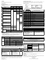
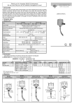
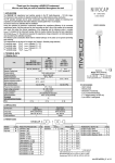
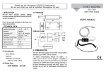
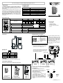
Thank you for choosing a NIVELCO instrument.
We are sure that you will be satisfied throughout its use!
1. APPLICATION
2. TECHNICAL DATA
The UNICONT PJK-1-4 is a universal interface module that
can be controlled via HART or MODBUS protocol through an RS485
interface, and (depending on type) provides relay(s) and/or 4…20 mA
current output(s).
The device is intelligent, the internal functions and services can be
set with the help of a communication protocol: the transmitter outputs
can be scaled. The error detection function can be switched on and
off. The state, in which a given output unit should be when an error
occurs, can also be set. The device can be used with Nivelco’s
MultiCONT PR -1- units as an output extension module,
and also as a peripheral device for PLC or PC controlled process
control systems.
2.1 GENERAL DATA
USER’S MANUAL
TYPE
Power supply
Current consumption
Ambient temperature
Electrical connection
Mechanical connection
Ingress protection
Weight
PJK-1-4
24VDC±10%
(10 mA + NRelay x 11mA + NCurrent generator x 25 mA) ±10%
-20 °C … +50 °C
max. 2.5 mm2 twisted, max. 4 mm2 solid cable
DIN EN 60715 rail
IP 20
≈ 0.11 kg
N: number of outputs of a given type of output units
2.2 TYPE SPECIFIC DATA
TYPE (A)
PJK-102-4
PJK-111-4
PJK-110-4
PJK-120-4
B
B
B
B
C
C
C
C
Current
generator
Relay
OUTPUT UNITS
– Output
– Rating
– Insulation voltage
– Electrical / Mechanical life span
– Pulse width in pulse mode
– Linear range
– Error indication
– Resolution
– Accuracy
– Temperature dependence
2.3 ACCESSORIES
− User’s Manual
− Certificate of Warranty
− Declaration of Conformity
− Description of the Communication
1 x SPDT
250 V AC, 8 A, AC1
2500 V 50 Hz
105 / 2 x 10⁶ switches
0.1..25,5s
Protocol
3.601 mA…21.999 mA
≤ 3.6 mA or ≥ 22 mA
14 bit
40 µA
max. 15 µA / 10°C
2.4 DIMENSIONS
4.2 RS485 COMMUNICATION TERMINALS
19,5
90
TB – terminator contact,
interconnect with point
„B”
B – negative terminal of
RS485 data connection
A – positive terminal of
RS485 data connection
SHLD – shielding
Wiring example when using a MultiCONT:
26,5
10
Connection with shielded twisted pair cable, shielding is
grounded at one point on the MultiCONT side.
21,5
36
58
2.5 ORDER CODE
P
J
K
–
CURRENT
OUTPUT
–
1x 4-20mA
2x 4-20mA
1
–
The Universal Interface Modules should be
connected one after another to one cable
pair. Star topology is not allowed. Max. cable
length is 1000 m, but in this case a shielded
twisted cable pair (STP – Shielded Twisted
Pair) should be used. Max. cable capacity
should be less than 100 pF/m.
All of the Universal Interface Modules in one
system should have different addresses
(0…31), see: 5.1.2.
The terminal resistor is connected to the two farthest points
of the cable. (TB and B contacts are connected in PJK 100;
and on the MultiCONT the K2 terminal resistor, located
next to the terminals, is switched on.)
4
Module RS485
A B COM
K2: terminal resistor
CODE
0
1
2
RELAY
ON
CODE
–
1x SPDT
2x SPDT
0
1
2
OFF
K2
3. MOUNTING
The PJK-1- device can be mounted on a DIN EN 60715 rail.
4. ELECTRICAL CONNECTION
24VDC TB B A
4.1 ELECTRICAL CONNECTIONS OF POWER SUPPLY AND OUTPUTS
POWER SUPPLY
RELAYS
CURRENT GENERATORS
24VDC TB B A
24VDC TB B A
PJK-102
PJK-120
PJK-111
relay module
4-20 mA module
relay + 4-20 mA module
5. INSTALLATION, SETTING UP AND PROGRAMMING
5.1. PREPARATION
–, + Terminals of the 24V
power supply.
Make sure that the wiring is
done with correct polarity!
De-energised relay:
C
– common contact
NO – normally open contact
NC – normally closed contact
I– – negative current
output
I+ – positive current
output
5.1.2 SETTING THE DEVICE ADDRESS
A communication line can contain max. 32
Universal Interface Modules. These modules
should have different addresses.
Set the address with the „ADDRESS” DIP
switches (0…31), on the front panel of the device.
Settings will take effect when the unit is switched
on again!
MODBUS
HART
On
ADDRESS
5.1.1 CHOOSING A COMMUNICATION PROTOCOL
Open the housing via the four snap-on clips to
access the DIP switch for protocol selection.
DEFAULT SETTING: HART
1
2
4
8
16
Example for
setting the
address:
4+8=12
pjk1024a0600h_01 ♦ 1 / 2
5.2. WIRING
See: 2. Technical Data and 4. Electrical connection
5.3.3.2 HART COMMUNICATION PROTOCOL
Physical format: RS485, Slave, RTU, 9600 Baud, 1-8-Odd-1. Device address is adjustable in 1…31
range. Detailed description of HART (standard 5) commands can be found in a separate document.
5.3. INSTALLATION
Logical set-up of the device:
5.3.1 POWER ON AND SELF TEST
After correctly wiring and switching the device on, it runs a few self tests whose results are shown with
LED indications.
’COM.’ LED-s
’STATUS’ LED-s
SEQUENCE OF SELF TESTS
1.
2.
1.
2.
1. Test of red LED-s:
Red
Red
2. Test of green LED-s:
Green
Green
DIP switch test:
Blinking green
Dark
Dark
Dark
3.
Green: OK.
Dark
Dark
Dark
result:
Red: Error
RESET button test:
Blinking green
Dark
Dark
4.
Green: OK.
result:
Dark
Dark
Red: Error
Detecting Relay on 1. unit:
Blinking green
Dark
Green: Exists
5.
Red: Error
result:
Dark
Dark: Doesn’t
exist
Detecting Relay on 2. unit:
Blinking green
Green: Exists
6.
Red: Error
result:
Dark: Doesn’t
exist
Detecting Current output on 1. unit,
Blinking green
(if relay doesn’t exists):
Green: Exists
7.
Red: Error
result:
Dark: Doesn’t
exist
Detecting Current output on 2. unit,
Blinking green
(if relay doesn’t exist):
Green: Exists
8.
Red: Error
result:
Dark: Doesn’t
exist
9. Peripheral self test results for 1sec:
EEPROM block test result
Green: OK. Green: OK.
(block1, block2):
Red: Error
Red: Error
If content of one block is erroneous, it
10.
is corrected from the other one, if both
Green: OK. Green: OK.
are erroneous, they are corrected by
loading default values:
Device is ready:
Pale green
Pale green
RAM, ROM,
Device is ready:
Pale green
Pale green
Dark
Dark
EEPROM
11.
tests and their Device is unable to
Red blinking together
results:
operate:
5.3.2 OPERATION
- After the self test sequence, if the device is ready for operation, states and operation of the module and
its units are shown as follows:
- ‘COM’ LED – indicates the communication with the unit that belongs to it, (all LED-s flash in case of
communication with the module), it also indicates the operation state of the device.
- ‘STATUS’ LED – indicates the state of the unit that belongs to it.
OPERATION STATES
LED:
COM.
STATUS
DISPLAY:
COMMENT:
PALE GREEN
Device is ready
GREEN FLASH
Successful communication
RED FLASH
Communication failure
RED
Communication cycle time-out
MODUL
Factory: 151
Type: 50
ID: xxxxxx
Polling: 0..31
GREEN
DARK
CURRENT GENERATOR UNIT
Current in linear range
-
RED
-
Error (signal) current
BLINKING RED
Relay error
Current generator error
Interpreted commands:
COMMAND
CODE
ADDRESSING
SHORT
LONG
RELAY UNIT PARAMETERS:
- 0...25.5 s pulse time
(non restartable)
- Configurable energised or
de-energised error state:
- for device hardware error
- for comm. cycle time-out
FACTORY
SETTING
0.1s
Off
Off
CURRENT GENERATOR UNIT
PARAMETERS:
- Configurable error-current
≤3,6 mA or ≥22 mA:
- for device hardware error
- for comm. cycle time-out
- Scaling values at 4 and 20 mA
•
•
•
•
•
•
•
•
•
•
•
•
•
•
•
•
•
•
•
•
•
•
•
•
Read Unique ID
Write Polling Address
Read Polling Address
Read Message
Read Tag, Descriptor, Date
Read Final Assembly Number
Write Message
Write Tag, Descriptor, Date
Reset ’Config Change Flag’
Write Device ID
Read Device Table
Read Firmware Version
13
18
201
202
203
204
205
206
-
•
•
•
•
•
•
•
•
Unit-level HART commands
Read Tag, Descriptor, Date
Write Tag, Descriptor, Date
Read Slot Output/Input
Write Slot Output
Read Slot Configuration
Write Slot Configuration
Write Slot Calibration
Read Firmware Version
5.3.4 OTHER OPERATING SERVICES
MODULE SERVICES:
Operating time count
COMMON SERVICES OF THE UNITS:
Communication watchdog (comm. cycle time-out)
RELAY UNITS’ SERVICES:
CURRENT GENERATORS’ SERVICE:
- Static or pulse output
- Monitoring correct operation of current
- Eligible pulse default state
generator (error indication)
- Detection of coil splitting (error indication)
- Sum of energised state times
- Nr. of switching cycles
- Life-time (max. numbers of switching cycles)
5.3.5. RESET, TEST MODE, AND LOADING FACTORY DEFAULTS
The mentioned operations can be done, without restarting the device, with the small recessed
‘RESET(TEST)’ button on the front panel:
TEST MODE
Once in test mode by consecutive pressing the ‘RESET(TEST)’ button you can cycle through the
following tests. Pressing this button until all Red LED-s are flashing will exit the test mode, without
pressing the button the device quits test mode after 30 seconds.
CONSECUTIVE TESTS:
CURRENT
GENERATOR UNIT
FACTORY
SETTING
Off
FACTORY
SETTING
Off
Off
Calibrated
5.3.3.1 MODBUS COMMUNICATION PROTOCOL
Physical format: RS485, Slave, RTU, 9600 Baud, 1-8-Odd-1. Registers of the device can be accessed
(read or write) with command 3 (Read Holding Registers) and command 16 (Preset Multiply Registers).
Device address is adjustable in 1...31 range only. Detailed description of registers can be found in a
separate document.
pjk1024a0600h_01 ♦ 2 / 2
Module-level HART commands
0
6
7
12
13
16
17
18
38
140
200
206
RELAY UNIT
5.3.3. PROGRAMMING, SETTING THE CURRENT GENERATOR AND RELAY OPERATION
Depending on the application, re-programming of the device may be needed. Programming can be done
with either a PC that controls the communication network via HART or MODBUS protocol, or a
MultiCONT (see MultiCONT’s User Manual). Parameters determining the operation:
Communication watchdog
UNIT 2.
Factory: 151
Type: 51
ID: xxxxxx+2
RESET:
- Press
Entering TEST mode:
- Press and Hold
Loading factory default settings: - Hold pressed while power on, and release when all LEDs flash red.
Attention! The current generator units should be recalibrated!
The HART long addresses will change!
RELAY UNIT
Energised
De-energised
PARAMETERS AVAILABLE FOR ALL UNITS:
UNIT 1.
Factory: 151
Type: 51
ID: xxxxxx+1
DIP SWITCH
energised
de-energised
3.6 mA
4 mA
12 mA
20 mA
22 mA
correct operation
- switching to left:
- switching to right:
’COM.’ LED-s:
(identifying tested unit)
’STATUS’ LED-s
correct operation:
Red
As described in 5.3.2
Flashing red together
Alternate flashing red
Red flashing
on 1st unit,
on 2nd unit.
6. MAINTENANCE, REPAIR
The device does not require regular maintenance.
Repair within and beyond the warranty period is carried out at the Manufacturer’s location.
7. STORAGE
Ambient temperature: -30 °C... +60 °C. Relative humidity: max. 98%
8. WARRANTY
All Nivelco products are warraned free of defects in materials or workmanship for a period of two years
from the date of purchase, as indicated in the Certificate of Warranty.
pjk1024a0700h_02
January, 2007.
Nivelco reserves the right of technical changes