1
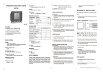
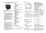
selec
EM368/EM368-B
Operating Instructions
Transmission distance
500 m maximum
BURDEN
0.5 VA@5A per phase
Transmission speed
300, 600,1200, 2400, 4800, 9600,19200
(in bps)
MEASUREMENT
Total active Energy (kWh)
Total reactive Energy (kVArh)
Total apparent Energy (kVAh)
Total active power (kW)
Total reactive power (kVAr)
Power factor (Individual & Average)
Note: All energies are resettable
FEATURES
! 8 digit LCD with backlight display
! User programmable CT primary, CT Secondary,
PT primary & PT Secondary
! User programmable network selection
! Memory retention
! Password protected energy reset
! Potential free Pulse output for energy
! 90 to 270V AC/DC auxiliary supply
! Battery backup (optional)
! RS485 communication (MODBUS Protocol)
RATED INPUT VOLTAGE
11 to 300V AC (L-N) ; 19 to 519V AC (L-L)
FREQUENCY RANGE
50/60 Hz
RATED INPUT CURRENT
Nominal 5A (Min-11mA, Max-6A)
Response time
100 ms (independent of baud rate)
TEMPERATURE
Operating: 0 to 50 OOC
Storage: -20 to 75 C
HUMIDITY
85% non-condensing
RESOLUTION
PT Ratio x CT Ratio
kWh
Pulse
<15
0.01K
0.01K
<150
0.1K
0.1K
DISPLAY
8 digit LCD display. Height 10.5mm
WIRING INPUT
3 Ø - 4 wire, 3 Ø - 3 wire, 2 Ø - 3 wire, &
1 Ø - 2 wire system
Stop bits
1 or 2
ACCURACY
Class 1 for Active/Apparent energy
Class 2 for Reactive energy
Class 0.5 for Power
SPECIFICATIONS
LCD INDICATIONS
INT - Integration of energy
X10 - Resolution is 10
REV - Reverse connected CT or Voltage wiring
- Communication in progress
- Pulse output
BAT - Battery backed display
Parity
None, Odd, Even
<1500
1K
1K
<15000
0.01M
0.01M
<150000
0.1M
0.1M
<1500000
1M
1M
≥1500000
10M
10M
NOTE:
1) For power, resolution is automatically adjusted
2) For power factor, resolution is 0.01
3) INT blinks after every 5 seconds, if load on any
one of three phase is present
AUXILIARY SUPPLY RANGE
90 to 270V AC/DC, 50/60Hz
OUTPUT
Pulse Output: Voltage range - 24V DC
Current capacity - 100 mA max
Pulse Width: 100 ms ± 50 ms.
CT PRIMARY
1A / 5A to 10,000A (Programmable for any
Value)
Note: 1A to 10,000A if CT secondary is 1 else
CT primary is 5A to 10,000A
SERIAL COMMUNICATION
Interface standard & protocol
RS485 & MODBUS RTU
CT SECONDARY
1A or 5A (programmable)
Communication address
1 to 255
PT PRIMARY
100V to 500kV (Programmable for any value)
Transmission mode
Half duplex
PT SECONDARY
100 to 500V AC (L-L)
(Programmable for any value)
Data types
Float and Integer
MOUNTING
Panel mounting
WEIGHT
310 gms
SAFETY PRECAUTIONS
All safety related codifications, symbols and
instructions that appear in this operating manual or
on the equipment must be strictly followed to ensure
the safety of the operating personnel as well as the
instrument.
If the equipment is not handled in a manner
specified by the manufacturer it might impair the
protection provided by the equipment.
CAUTION: Read complete instructions prior to
installation and operation of the unit.
CAUTION: Risk of electric shock.
WIRING GUIDELINES
WARNING:
1. To prevent the risk of electric shock power supply
to the equipment must be kept OFF while doing
the wiring arrangement.
2. Wiring shall be done strictly according to the
terminal layout. Confirm that all connections are
correct.
3. Use lugged terminals.
4. To eliminate electromagnetic interference use
of wires with adequate ratings and twists of the
same in equal size shall be made.
5. Cable used for connection to power source,
must have a cross section of 1.5mm2. These
wires shall have current carrying capacity of 6A.
MAINTENANCE
1. The equipment should be cleaned regularly to
avoid blockage of ventilating parts.
2. Clean the equipment with a clean soft cloth .
Do not use Isopropyl alcohol or any other
cleaning agent.
INSTALLATION GUIDELINES
CAUTION:
1. This equipment, being built-in-type, normally
becomes a part of main control panel and in
such case the terminals do not remain
accessible to the end user after installation and
internal wiring.
2. Conductors must not come in contact with the
internal circuitry of the equipment or else it
may lead to a safety hazard that may in turn
endanger life or cause electrical shock to the
operator.
3. Circuit breaker or mains switch must be
installed between power source and supply
terminals to facilitate power 'ON' or ‘OFF’
function. However this switch or breaker must
be installed in a convenient position normally
accessible to the operator.
4. Before disconnecting the secondary of the
external current transformer from the
equipment, make sure that the current
transformer is short circuited to avoid risk of
electrical shock and injury.
CAUTION:
1. The equipment shall not be installed in
environmental conditions other than those
mentioned in this manual.
2. The equipment does not have a built-in-type
fuse. Installation of external fuse of rating
275VAC/1Amp for electrical circuitry is highly
recommended.
MECHANICAL INSTALLATION
For installing the meter
1. Prepare the panel cutout with proper dimensions
as shown below :
W
NE
Panel cutout
dimensions (in mm)
Outline dimensions (in mm)
90.5 91.5
99
99
Front bezel
5
50
Side view
Operating/1006/EM368/OP277-V01
91.5
Panel Cutout
Page 1 of 4
2. Push the meter into the panel cutout. Secure
the meter in its place by pushing the clamp on
the rear side. The clamps must be secured in
diagonally opposite slots.
NOTE:
By default total active energy (kWh) will be
displayed all the time and at momentary key press
unit shall display the corresponding page for 5 sec.
3. For proper sealing, tighten the screws evenly
with required torque.
Keys Description (Configuration)
CAUTION:
The equipment in its installed state must not come
in close proximity to any heating sources, caustic
vapors, oils, steam, or other unwanted process
by-products.
EMC Guidelines:
1. Use proper input power cables with shortest
connections and twisted type.
Sr
No
To enter into configuration
1 mode.
for 3 seconds
To scroll through the
2 pages in forward direction
go to next page
To scroll through the
pages in reverse direction
in configuration mode.
To increase and decrease
4 all parameter values
+
N
+
RS485
Key press
-
Display
Increase
Decrease
Press
\
CONNECTION DIAGRAM
L
O
A
D
L1
L2
L3
N
S2
S2
S1
S1
I2
I1
S2
V1
N
V2
V3
Press
Range:
0 to 9998
key for next parameter
2. Change password
Press
\
selec
EM368
MD BAT
DATE R TIME
kWhr
INT
Range:
No / Yes
Press for next parameter
Note: If ‘NO’ then after pressing
key, menu
will go to network selection
Factory setting: 0
PF
kWh
kW
kVArh
kVAr
Display
Press
\
PF
P
Q
E
PRG
Keys Description (Online pages)
Keys
Function
Press
Press
Display
)
To view total active power
Press
\
Q(
)
To view total reactive power
E(
)
To view total reactive &
apparent energy
PF (
2
P(
3
4
)
Range:
0 to 9998
for next parameter
for previous parameter
4. Network selection
To view individual and average
power factor
1
Press
Press
8. PT primary
Factory setting: 3P - 4W
Range:
3 Ø - 4 wire
3 Ø - 3 wire
Press for next parameter
Note: For 2 Ø 3 wire, 1 Ø 2 wire select 3 Ø 4 wire
network
Range:
300, 600, 1200,
2400, 4800,
9600 & 19200
Press for next parameter
Press for previous parameter
(Optional, available in EM368-C)
Factory setting: None
Display
Press
\
Range:
Even, Odd, None
Press for next parameter
Press for previous parameter
(Optional, available in EM368-C)
13. Stop bit
Factory setting: 1
Range:
100 to 500V AC (L-L)
for next parameter
for previous parameter
Range:
1/2
Press for next parameter
Press for previous parameter
(Optional, available in EM368-C)
14. Reset energy
Factory setting: No
Factory setting: 350
Display
Press
\
Press
Press
9. Battery backup
Press
\
Range:
100V to 500kV
for next parameters
for previous parameter
Factory setting: No
Display
Press
\
kVAh
Press
\
Press
\
kVAhh x10
3. New password
Factory setting: 9600
Display
Display
Display
FRONT PANEL DESCRIPTION
11. Baud rate
Description
Factory setting: 350
Factory setting: No
Display
Display
12. Parity
Range:
5 to 10,000A OR
1 to 10,000A
Press for next parameter
Press for previous parameter
Note: 1 to 10,000A if CT secondary is 1 else
CT primary is 5 to 10,000A
Press
\
I3
PF REV
Factory setting: 5
6. CT primary
Description
Display
Sr
No
Press
Press
Range:
1A or 5A
for next parameter
for previous parameter
Press
\
Factory setting: 10
1. Password
S1
Press
\
Key press
Display
Display
7. PT secondary
-
Factory setting: 5
5. CT secondary
go to previous page
L
PULSE O/P
Description
Display
CONFIGURATION SCHEME (parameter setting)
To enter configuration: Press & for 3 sec
TERMINAL CONNECTIONS
Display
in configuration mode.
3
2. Layout of connecting cables shall be away from
any internal EMI source.
&
Key press
Press
Press
10. Slave ID
Press
Press
15. Password
Factory setting: 11
Display
Range:
No / Yes
for next parameter
for previous parameter
Factory setting: 1
Press
\
Range:
1 to 9999
Press for next parameter
Press for previous parameter
Note: Password is : configuration password +1
16. Reset Active Energy
Factory setting: No
Display
Display
Press
\
Range:
No / Yes
Press for next parameter
Press for previous parameter
Note: If ‘NO’ then after pressing key, menu
will go to Network selection
Range:
1 to 255
for next parameter
for previous parameter
(Optional, available in EM368-C)
Press
\
Range:
No / Yes
Press for next parameter
Press for previous parameter
Note: User should note the reading before resetting
Operating/1006/EM368/OP277-V01
Page 2 of 4
= X10: X10 on the LCD is ON when the
Factory setting: No
Display
LOAD
L1
L2
LINE
LOAD
N
L1
L3
I1
S1
Press
\
Range:
No / Yes
Press for next parameter
Press for previous parameter
Note: On pressing key, configuration will go to
network selection page.
If ‘yes’ selected unit will be formatted to factory
setting
I2
S1
L
S2
VN
I3
S1
L
S2
N
I3
S1
PULSE OUTPUT
+
N
This symbol on the LCD indicates that a
pulse output is available.
PULSE OUTPUT
1 PHASE 2-WIRE (COMMONLY USED) WIRING DIAGRAM
+
1 Ø - 2 wire, 1 CT
3 Ø - 3 wire, 2 CT’s & 2 PT’s
TYPICAL WIRING DIAGRAM
LINE
LINE
LOAD
LOAD
3 PHASE 4-WIRE (COMMONLY USED) WIRING DIAGRAM
N
L2
L3
3 Ø - 4 wire, 3 CT’s
LINE
LOAD
L1
L2
L3
V1
S2
N
I1
V1
S2
I1
S1
S1
V2
V2
V3
S2
I2
Exit configuration mode:
V3
CT
I1
S1
S1
L
S2
L
I3
S2
V3
S1
I3
CT
I2
S1
S1
VN
VN
V2
S2
N
VN
PULSE OUTPUT
N
L
Note:1) Pressing
key will save the value of the
current parameter and move on to next
parameter.
S1
CT
mode.
! Power OFF and power ON the unit again.
I2
CT
S2
V1
S2
! Press
& key for 3 sec in configuration mode
! Do not press any key for 30 sec in configuration
2) Continuous operating of or key makes
parameter value update speed faster in 3
stages after 7 seconds
L
L1
CT
Display
=
VN
V3
S2
CT
Factory setting: No
I2
CT
Range:
No / Yes
Press for next parameter
Press for previous parameter
Note: User should note the reading before resetting
V3
S2
V2
S1
working on battery in absence of auxiliary
supply. The display will turn OFF after 48 hrs
when operated in battery backup mode
continuously. No measurement or output
will take place in this mode.
Press
\
V2
V1
S2
CT
This symbol on the LCD shows that the
communication is in progress.
CT
=
CT
I1
S1
= BAT: BAT on the LCD shows that the unit is
Display
V1
S2
CT
Factory setting: No
L2
reversal of one or more CT connections / Phase.
In such cases meter may not indicate the
correct energy consumption. The CT should
be connected to the meter with correct
polarities.
Range:
No / Yes
Press for next parameter
Press for previous parameter
Note: User should note the reading before resetting
19. Default value
LINE
3 Ø - 3 wire, 2 CT’s
= REV: REV on the LCD gives the indication of
Press
\
18. Reset Reactive Energy
2 Ø - 3 wire, 2 CT’s & 2 PT’s
3 PHASE 3-WIRE WIRING DIAGRAM
resolution is 10. It is the indication of count
reading which must be multiplied by 10 to
get actual kWh / kVArh / kVAh consumed.
CT
17. Reset Apparent Energy
Description
CT
Display
CT
Key press
PULSE OUTPUT
+
S2
+
CT
I3
S1
N
CONNECTION DIAGRAM FOR COMMUNICATION
PULSE OUTPUT
2 PHASE 3-WIRE WIRING DIAGRAM
+
2 Ø - 3 wire, 2 CT
3 Ø - 4 wire, 3 CT’s & 3 PT’s
LINE
LINE
LOAD
L1
Master
L2
LOAD
L1
N
L2
L3
N
3) In configuration menu repeated pressing
of key will allow toggling between all the
configuration parameters
RS232-RC485
CONVERTER
I1
S1
V2
CT
S1
V2
V3
S2
I2
V3
S2
I2
S1
CT
What does the INT, REV, X10, COM & BAT on
the LCD display indicate?
S1
selec
CT
USER GUIDE
I1
CT
S2
V1
S2
Suggested terminating resistor
(120 ohm, ¼ watt)
+
V1
EM368
PF REV
VN
VN
MD BAT
DATE R TIME
L
kWhr
PF
kWh
kW
I3
S1
kVArh
kVAr
I3
S1
CT
visual indication of energy integration. INT
indication keeps blinking once in 5 sec, for
presence of voltage & current in any of the
three phases.
S2
S2
CT
L
= INT: The INT on the LCD provides quick
INT
kVAhh x10
PF
Q
PRG
EM368
PF REV
MD BAT
DATE R TIME
kWhr
E
INT
kVAhh x10
PF
kWh
kW
kVArh
kVAr
kVAh
P
selec
PF
Q
EM368
PF REV
MD BAT
DATE R TIME
kWhr
E
PRG
INT
kVAhh x10
PF
kWh
kW
kVArh
kVAr
kVAh
P
selec
PF
kVAh
P
Q
E
PRG
N
N
PULSE OUTPUT
+
PULSE OUTPUT
+
Operating/1006/EM368/OP277-V01
Page 3 of 4
MODBUS register addresses list
APPLICATION OF PULSE OUTPUT
Range
Address
Hex Address
Parameter
Min value
Max value
40000
0x00
New Password
1
9998
40001
0x01
N/W selection
Value
Meaning
0
1
40002
0x02
CT Secondary
Float
Float
Float
Float
Float
Float
Float
Float
Float
Length
Data
(Register) Structure
1
Integer
3P-4W
1
Integer
Write Value
3P-3W
CT Secondary
1
Integer
1
1A
5
5A
5A (CT Sec = 5A)
10000A
1
Integer
40003
0x03
CT primary
1A (CT Sec = 1A)
10000A
1
Integer
40004
0x04
PT Secondary
100V
500V
1
Integer
40005
0x05
PT primary
100V
2
Integer
40007
0x07
Batt Back up
Value
500kV
Meaning
0
No
1
Integer
1
Yes
Baud rate
0x0000
300
0x0001
600
0x0002
1200
0x0003
2400
0x0004
4800
0x0005
9600
0x0006
19200
Value
Parity
0x0000
None
0x0001
Odd
0x0002
Even
Value
Stop bit
0x0000
1
0x0001
2
40010
40011
40012
0x0A
0x0B
0x0C
Parity
Stop bits
Reset kWh
P
L
C
N
PULSE OUTPUT
+
Pulse output from EM368 meter can be interfaced
into a process through a PLC for on line control of
energy content in the process.
If the PLC has a self excited 24V digital input,
external 24 VDC supply is not needed.
The kWh pulse is also used to derive average
kWh information at the PLC.
! ENERGY CONTROLLER
V3
I2
VN
L
I3
I/P
255
Value
I3
24 VDC
+
+
O/P
1
Baud rate
L
COUNTER
Slave Id
0x09
VN
V2
CT primary
0x08
V3
I2
V1
0x03
40009
V2
I1
40003
40008
V1
I1
CT
2
2
2
2
2
2
2
2
2
CT
Active Energy
30000
0x00
Apparent Energy
30002
0x02
Reactive Energy
30004
0x04
30006
0x06
Power Factor Phase 1
30008
0x08
Power Factor Phase 2
30010
Power Factor Phase 3
0x0A
Average Power factor
30012
0x0C
30014
0x0E
Total kW
30016
0x10
Total kVAr
Readable / Writable parameters from EM368
! PROCESS INTEGRATION
CT
Length
Data
(Register) Structure
Parameter
CT
Hex Address
CT
Address
CT
Readable parameters from EM368
To
Control
Circuit
N
PULSE OUTPUT
+
+
12 / 24V DC
1
Integer
1
Integer
1
Integer
1
Integer
Pulse output from EM368 meter can be used as
alarm generator or total energy controller by
interfacing it with presettable counter and control
circuits (Contactors, Relay, Trip Circuit).
The counter is loaded with the maximum energy
consumption. When count reaches setpoint it
provides output to control circuit to take
appropriate action.
Order Code Information
! EM368 (Without communication version)
! EM368-C (With communication version)
(Specifications subject to change as development
is a continuous process).
Selec Controls Pvt. Ltd., India
Value
Meaning
1
Reset Active Energy
1
Integer
Integer
Integer
40013
0x0D
Reset kVAh
1
Reset Apparent Energy 1
40014
0x0E
Reset kVArh
1
Reset Reactive Energy 1
Tel:91-22-28476443/1882, Fax:91-22-28471733,
Toll free: 1800 227 353, Website: www.selec.com
E- mail: [email protected].
Operating/1006/EM368/OP277-V01
Page 4 of 4