1
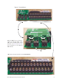
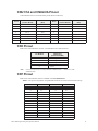
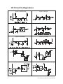
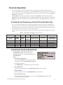
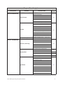
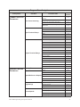
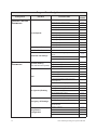
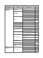
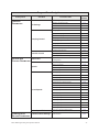
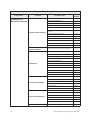
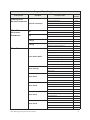
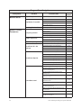
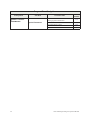
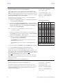
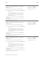
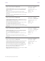
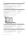
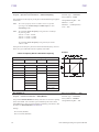
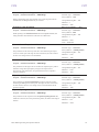
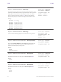
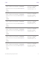
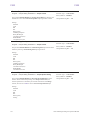
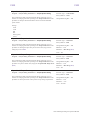
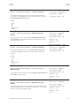
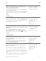
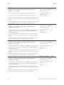
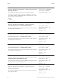
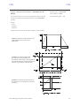
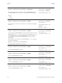
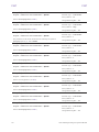
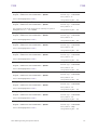
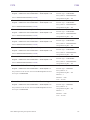
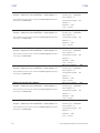
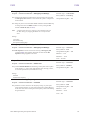
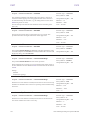
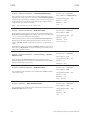
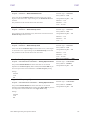
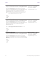
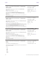
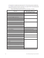
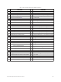
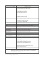
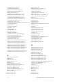
CNU1/1A and CNU2/2A Pinout
Control Board CNU1/1A and CNU2/2A pinout (RJ-45 connectors).
Pin #
CNU1 Pinout
(Control Board)
CNU1A Pinout
(EOI)
Pin #
CNU2 Pinout
(Control Board)
CNU2A Pinout
(EOI)
1
P24
P24
1
P24
P24
2
Gnd
Gnd
2
Gnd
Gnd
Tx
3
Tx (-)
RXA
3
Rx
4
Rx (+)
TXA
4
Gnd
Gnd
Rx
5
Rx (-)
TXB
5
Tx
6
Tx (+)
RXB
6
Gnd
Gnd
Open
Gnd
7
RS232/RS485
CNU3 Pin-7
7
Open
8
Gnd
Gnd
8
Gnd
CN3 Pinout
CN3 of the Control Board is used for 2-wire RS485 serial communications.
Pin Number
Note:
CN3 Pinout
(Controller PCBA)
1
RS485 Signal +
2
RS485 Signal -
3
RS485 Signal Gnd.
4
Shield
CNU2 or CNU3 may be used for RS485 communication — Cannot use both
simultaneously.
CN7 Pinout
CN7 of the Control Board connects to CN7A of the Terminal Board.
Table 2. CN7 pinout assignments. Programmable terminals are listed as their default settings.
Pin Number
Function
Pin Number
Function
1
PP
14
II
2
FL
15
S1
3
VI
16
R
4
RR
17
S3
5
FM
18
S2
6
RX
19
N15
7
FP
20
S4
8
AM
21
P15
9
*OUT1
22
P24
10
*OUT2
23
CC
11
ST
24
CC
12
RES
25
CC
13
F
—
—
Note: * Open collector outputs.
HX7 ASD Programming and Operation Manual
13