1
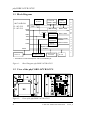
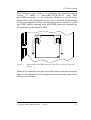
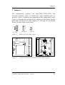
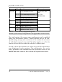
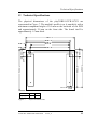
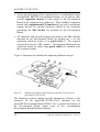
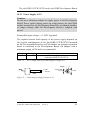
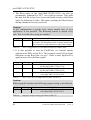
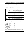
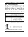
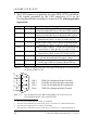
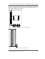
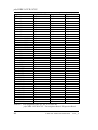
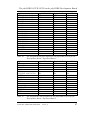
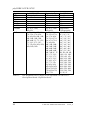
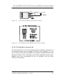
Pin Description 2 Pin Description Please note that all module connections are not to exceed their expressed maximum voltage or current. Maximum signal input values are indicated in the corresponding controller manuals/data sheets. As damage from improper connections varies according to use and application, it is the user’s responsibility to take appropriate safety measures to ensure that the module connections are protected from overloading through connected peripherals. As Figure 3 indicates, all controller signals extend to surface mount technology (SMT) connectors (0.635 mm) lining two sides of the module (referred to as phyCORE-connector). This allows the phyCORE-167CR/167CS to be plugged into any target application like a “big chip”. A new numbering scheme for the pins on the phyCORE-connector has been introduced with the phyCORE specifications. This enables quick and easy identification of desired pins and minimizes errors when matching pins on the phyCORE module with the phyCORE-connector on the appropriate PHYTEC Development Board or in user target circuitry. The numbering scheme for the phyCORE-connector is based on a two dimensional matrix in which column positions are identified by a letter and row position by a number. Pin 1A, for example, is always located in the upper left hand corner of the matrix. The pin numbering values increase moving down on the board. Lettering of the pin connector rows progresses alphabetically from left to right (refer to Figure 3). PHYTEC Meßtechnik GmbH 2002 L-527e_8 7