1
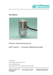
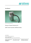
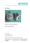
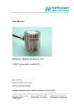
holthausen
elektronik GmbH
User Manual
Electronic Vibration Monitoring Unit
ESW®-Mini (hol550)
date: 04.03.2014
document: hol550_hb_e.doc
technical modification possible
holthausen elektronik GmbH is certified according to DIN EN ISO 9001.
holthausen elektronik GmbH
Wevelinghoven 38
41334 Nettetal
Phone: +49 (0) 21 53 - 40 08
Fax: +49 (0) 21 53 - 89 99 4
[email protected]
www.holthausen-elektronik.de
Electronic Vibration Monitoring Unit
ESW®-Mini (hol550)
holthausen
elektronik GmbH
Table of contents:
1. Generally basical safety-indications ..................... page 4
2. Packing and the transport .................................... page 6
3. Appliance documentation ..................................... page 7
4. Grounding-concept ............................................... page 8
5. Function ............................................................... page 9
6. Visual and tactile elements................................... page 10
7. Switching of the measurement range ................... page 10
8. Limit range adjustment ......................................... page 10
9. Version with step switch ....................................... page 11
10. Version with potentiometer ................................... page 11
11. Cable connection draft ......................................... page 12
12. Assembling and implementing ............................. page 13
11.1 Mounting of the vibration monitoring unit ..... page 13
11.2 Connection of the vibration monitoring unit .... page 13
13. Safety-Installation................................................. page 14
14. How the ESW ®-Mini works ................................... page 14
15. Maintenance......................................................... page 14
16. Mechanical data ................................................... page 15
17. Drill template ........................................................ page 16
Declaration of Conformity ..................................... page 17
Technical data ...................................................... Attachment
2
Electronic Vibration Monitoring Unit
ESW®-Mini (hol550)
holthausen
elektronik GmbH
Important information
These operation instructions are to be read through completely and carefully heeded
before starting the device. Failure to heed or adhere can result in claims on
manufacturer’s liability becoming null and void for damages ensuing there from.
Manual action of any manner on the device – with the exception of proper procedures
and those described in these operation instructions – lead to forfeit of guarantee and
exclusion from liability.
The device is solely intended for the usage as described below. It is particularly not
intended for the direct or indirect protection of persons.
holthausen elektronik GmbH assumes no liability whatsoever as regards suitability for
some specific purpose.
If any question should remain open, please never hesitate to contact us.
holthausen elektronik GmbH
Wevelinghoven 38, 41334 Nettetal
Phone: +49 (0) 21 53 - 40 08, Fax: +49 (0) 21 53 - 8 99 94
Mail: [email protected]
3
Electronic Vibration Monitoring Unit
ESW®-Mini (hol550)
holthausen
elektronik GmbH
1. Generally basical safety-indications
Don’t use this device as the only invigilator, if a malfunctioning of ESW ®-Mini could lead
to damages on goods or Persons.
To obtain the desired result be sure, that the device with its technical data fits to the
bulk of the object you want to supervise.
The sensor is sensitive to shock. A downfall out lower height to a hard substratum can
destroy the sensor.
The assembling place and the execution of the assembling of the sensor determine
decisively the quality of the sensor signal. The assembling may only happen through
qualified and instructed persons.
The electrical hook up is to be done by instructed persons. A mistake by the connection
can entail to faulty functions, outfall or ruination of the sensor and electronics.
The ESW ®-Mini should not be used on machines with a very energetic high-frequency
solid-borne. Through resonance apparitions in the sensor, the device can indicate a
much too great or too small value.
Powerful noise sources for instance inverters, in direct closeness of the sensor,
electronics or cabling, can result in faulty behaving of the apparatus.
Potential differences and balance currents in the mass guidance can result in faulty
behaving too.
The connection cable is resistant against many but not every type of chemicals.
Through a damaged cable chemicals could get inside the unit and destroy the
electronic. Then the unit would loose their function.
Therefore the conditions from the mounting surrounding must be checked. Then the
cover material from the cable have to be proofed if it resists these requirements. You
can get an overview from the chemical resistance of the cover material from us.
4
Electronic Vibration Monitoring Unit
ESW®-Mini (hol550)
Safety instructions
holthausen
elektronik GmbH
in this manual are marked with Symbols.
The safety instructions are introduced by signal words that
express the extent of the hazard. Observe the safety and act
prudently to prevent accidents, personal injury and property
damage.
DANGER!
… indicates an imminently hazardous situation that will result
in death or serious injury if not avoided.
WARNING!
… indicates a potentially hazardous situation that may result
in death or serious injury if not avoided.
CAUTION!
… indicates a potentially hazardous situation that may result
in minor or moderate injury if not avoided.
CAUTION!
… indicates a potentially hazardous situation that may result
in property damage if not avoided.
Tips and recommendations
NOTE!
… highlights useful tips, recommendations and information
for efficient, trouble-free operation.
5
Electronic Vibration Monitoring Unit
ESW®-Mini (hol550)
holthausen
elektronik GmbH
2. Packing and the transport
CAUTION!
The sensor is sensitive to shock. A downfall out lower height to an hard
substratum can destroy the sensor.
Avoid to kink or tie a knot in the cable.
Keep the electronic in a dry place.
In case of a downfall or heckling or squeezing, could the casing or the
operation elements or the board get defects.
With adequate warning-labels and through a qualified packaging and storage, you can
protect the sensor and electronics at carriage against influences from outside.
6
Electronic Vibration Monitoring Unit
ESW®-Mini (hol550)
holthausen
elektronik GmbH
3. Appliance documentation
In many technical ranges there are vibrations, frequently are they to neglect or even
necessary, but sometimes also undesirable or even dangerous.
Beside that, can dangerously vibration-conditions start slinking or occur total
unexpected.
The reason for it often lies in mechanical defectives or improper handling of the
machine.
The sequences are maybe diminution of the product quality or even loss of production
and endangering of the security, at least a raised wear and tear.
Increasing automation as well as a high noise level, prevents often an acoustically or
visual surveillance.
Thereby offers early detection, taking care of the material and limitation of damage a
considerable potential to the reduction in costs.
The ESW ®-Mini for the vibration surveillance delivers important information to the
running process, provides the proof of slow changes and reacts at exceeding of limit
values.
As the unit of measurement, are according to the application, the measured vibration
acceleration (measurement of power), the measured vibration velocity (measurement
of the energy) or the measured vibration movement (measurement of movement)
usual.
The frequency range and the unit of measurement result from the characteristics of the
measured object and the environmental reference. Depending on the measured object
occurs the signal estimation according to the crest value or the effective value of the
measurement.
The actual measurement is given out in form of a 4 to 20mA analog-signal that can be
used without any disturbance for longer cable interconnections.
Particular attention should be donated to the assembling place of the sensor, decisively
is the source of the signal that shall be measured and its mean vibration direction.
The assembling place of the sensor and alignment of the measurement axis of the
sensor have to be selected so that the vibration possibly can be measured directly
without interferences, subdued crossings or defective couplings.
7
holthausen
Electronic Vibration Monitoring Unit
ESW®-Mini (hol550)
elektronik GmbH
4. Grounding-concept
main control box
with power supply
optional
connection box
vibration
control unit
shield
shield
+Ub
-Ub
signal ground
signal ground
vibration control unit ground
local
vibration control unit ground
main control
box ground
connection box ground
local
connection box ground
local
main control box ground
If an isolated installation is not explicit requested, usually through the screw of the
components the casing is connected to the local machine ground.
The cable shielding, the box ground and the signal ground could be connected, inside
an optional terminal box, dependent on local facts and requirement.
Inside the ESW ®-Mini, depended on customers request, the shielding and / or signal
ground is connected with the case potential, by the factory.
Connection to the local Ground
In big facilities with considerable energy consumption and distances between the
machines such big potential difference could be build up, that substantial balancing
current will occur on the ground network. Dependent on intensity of such currents are
disturbances or damaging of the unit the result!
Potential differences could also arise on machines, with small distances, not clear
crossings of the ground potential (painting) or movable parts (feathers, suspension
mounting) could be the reason for regular potential-steps.
High energetic frequency interferences could also be added to the measurement signal
wire by inductively or through capacity coupling and could change the real existing
measurement value! In this way could for example parallel going elements act as
coupling capacity and winded grounding cable act like a choke.
CAUTION!
Ground is not equal everywhere!
Check the situation
Plan the grounding concept
Select the facility / realization
8
Electronic Vibration Monitoring Unit
ESW®-Mini (hol550)
holthausen
elektronik GmbH
5. Function
The vibration-monitoring unit is generally mounted on the place, where inadmissible
vibration occurs or can be expected. The unit is permanently monitoring the real
condition or situation on the machine. The noticed mechanical vibration detected by
the sensor will be transformed to a corresponding electrical signal.
The following evaluation electronic, filters and treats the measurement signal on such
way, that an output signal occurs, which allows a clear and topical judgment also in the
critical range.
The output signal is compared with an adjustable reference level. In case the
measured value exceed the reference level for longer than the specific delay time, an
alarm relay will be activated, to drive any warn- or control-functions. By customer
request the delay time is directly adjusted by the factory.
In case the measured value falls below of the reference level, the alarm relay will
change back to neutral position after the end of the delay time. Also this time can, by
customer request, directly be fixed by factory.
Operating range in relation to the frequency (valid for the internal sensor ADXL321):
200
operating range in mm/s
180
160
140
120
100
80
60
40
20
0
0
200
400
600
800
1000 1200 1400 1600 1800 2000
frequency in Hz
9
Electronic Vibration Monitoring Unit
ESW®-Mini (hol550)
holthausen
elektronik GmbH
6. Visual and tactile elements
NOTE!
Not all functions are present in all versions
LED1
LED3
LED2
On
4
3
5
6
7
8
2
1 0 9
ST1
1 2 3 4 5 6 7
ST2
Draw: Insight and full equipped (depending on version)
LED1 (green): power on connected
LED2 (yellow): Measuring is greater than settled range
LED3 (red):
as long as the alarm relay in the alarm setting remains
7. Switching of the measurement range (option) (ST2: S6 and S7)
To change the measurement range, you can use the 2 DIP-switches. At the lower
position the DIP-switches are turned OFF, equivalent to “0” level, at the higher position
equivalent to “1” level the DIP-switches are switched ON.
The measurement range in the following should be understand like an example. Other
measurement ranges are realizable in specified ranges on customer request.
Please take care during the adjustment, not to destroy or to shift any other adjustment
element. You should absolutely safe the unit for entering of dirt, humidity or other alien
element. After finishing the adjustment, make sure to close the unit perfectly and check
that the cover is solid closed.
10
holthausen
Electronic Vibration Monitoring Unit
ESW®-Mini (hol550)
elektronik GmbH
Measurement range
Position
Version 1
Version 2
S6
S7
10mm/s
15mm/s
OFF
OFF
20mm/s
30mm/s
ON
OFF
50mm/s
45mm/s
OFF
ON
60mm/s
60mm/s
ON
ON
8. Limit range adjustment (ST1)
One of the main goals of the device is, after exceeding a specified measurement
value, to activate the alarm relay for execution of specified effects. In order to meat
real conditions at the measurement place, the switch level of the measurement value
could be adjusted. For this reason there is an adjustment element in the device to set
the limit of the measurement value between 10% and 100%. This adjustment should
only be done by qualified persons, when the device is disconnected from the power
supply. Dependent on the version of the device, the adjustment element is a step
switch or a potentiometer.
9. Version with step switch (ST1)
The step switch is adjustable with a small screwdriver, blade width 3mm. On top of the
step switch there are numbers from 0 till 9. The number 1 means, the limit value of
10%, for example the number 6 correspond to the limit value of 60% and 0 means
100% from the measurement range. The switch has no mechanical limitation and could
be turned over 360°, without any risk.
10. Version with potentiometer (ST1)
The potentiometer is adjustable with a small screwdriver, blade width 3mm. Around of
the potentiometer exists a scale with numbers from 10 till 100. The number 10 means
10% of the measurement range and 100 means 100%. This potentiometer has a
continuous adjustable range, with a turning angle of 300° between both mechanical
limits.
11
Electronic Vibration Monitoring Unit
ESW®-Mini (hol550)
holthausen
elektronik GmbH
Please take care during the adjustment, not to destroy or to shift any other adjustment
element. You should absolutely safe the unit for entering of dirt, humidity or other alien
element. After finishing the adjustment, make sure to close the unit perfectly and check
that the cover is solid closed.
12
Electronic Vibration Monitoring Unit
ESW®-Mini (hol550)
holthausen
elektronik GmbH
11. Cable connection draft
CAUTION!
Please notice the cable connection information in the specific technical
data for each Version.
ESW ®-Mini (example shows version 005)
+24V supply volt.
ground
pink
blue
grey
white
yellow
green
brown
analog output
analog ground
closer contact
middle contact
opener contact
: +24V supply voltage
: Ground
: analog output
: analog ground
: closer contact
: middle contact
: opener contact
shield : see page 6 ´Grounding Concept´
The outlined contacts of the alarm relay show the position disconnected
to the power supply. Normally closer- and middle contact are connected.
normally the cable shield is connected to the casing
13
Electronic Vibration Monitoring Unit
ESW®-Mini (hol550)
holthausen
elektronik GmbH
12. Mounting and maintenance
The sensor can only take up the vibrations and transmit them, which really arrive on his
assembling place. Therefore the choose of the right assembling place is very
important.
Also the method of mounting has decisive influence on the quality of the sensor signal
and has to be done very carefully.
12.1 Mounting of the vibration monitoring unit
CAUTION!
The mounting is to be done by qualified persons!
Protect the sensor definitely against drop, stroke
and other mechanical shock!
Before mounting the vibration monitoring unit, please define the main vibration direction
and than select the measurement place, which is as much as possible free of own
vibration and interferences and has enough space to mount the ESW ®-Mini exact to
the vibration direction (picture 1, page 13).
With help of appropriate drill template (picture 3 and picture 4, page 14) it’s easy to
place the corresponding hole to the mounting place. Around of the mounting place is a
sufficiently large and plane place for the unit necessary, it should be oriented vertically
to the mounting holes and to the direction of the vibration. After finishing the mounting,
the connection wire and also the sensor wire (by external sensor) will be placed.
Please make sure that connection cable is flexible enough not to tear off by excessive
vibrations, on the other hand it should be firmly fixed to avoid making noise itself, to be
safe for damage in normal work and not to become a trip wire.
Please note the minimum bending radius in the technical datasheet.
In the case of using a mounting plate a maximum torque of 30Nm is to be kept. The
power transmission must be influenced only at the hexagonal bolt.
12.2 Connection of the vibration monitoring unit
ATTENTION!
All the connection work may exclusively be carried out through qualified
persons and only in the non-voltage condition!
The ESW ® has a fixed connection wire. To make further connections easy lead the
cable into a switchbox or control center. The requested power supply is 24V DC
(±10%) and should be stabilized without any disruption and interferences. The power
line should not be placed near to any disruption sources, like a rectify. For additional
information to the issue interference sources, grounding and shielding, see on page 6
the “grounding-concept”.
The maximal power load on the relay contacts is 30V and 1A. Please pay attention to
the working method of the relay. The description of the relay contacts is always related
to a voltage less condition. After switching of power supply ON, without an alarm
condition, the alarm relay is attracted.
14
Electronic Vibration Monitoring Unit
ESW®-Mini (hol550)
holthausen
elektronik GmbH
In case of an alarm, voltage drop or disconnection, the connection between middle
contact and closer contact is interrupted. This circumstance allows to control if there is
a faulty or a breakdown.
The optional analog current output is realized by factory as a current of 4 to 20mA. The
load should not exceed more than 500Ohm.
If the unit is equipped with an alarm memory, an external reset button is necessary.
The reset is activated, when the control wire is connected for a short time with ground
potential of the unit.
13. Safety measure
At regular function the sensor delivers a short-circuit current, on which the
measurement signal is modulated on. The evaluation electronic controls the signal and
gives alarm, as soon as the signal has leaved its allowed range. So are sensor failure,
disconnection and short circuit of the sensor cable controlled permanently. The alarm
relays have attracted in quietscence. At alarm, voltage outfall and cable fraction of the
switching cable becomes alert condition signalled. The analog output gives a 4 to
20mA signal. Sinks the electric energy against 0mA or rises it distinct over 20mA,
signals that cable fraction or short circuit.
14. How the ESW®-Mini works
The evaluation works maintenance free and needs no one further attention. It must be
secured, that the apparatus settings can not be manipulated unchecked. In the daily
work should sporadically be checked, whether the display shows realistically values.
Too great or too small values can point out to changes at the machine, to the
measurement settings or to the environmental reference conditions. The ideal settings
for the device may be different from machine to machine and must be adjusted if
necessary.
15. Maintenance
The device needs no special maintenance. The maintenance restricts to exchange
defected parts. Should the equipment be sent to the fabricators for restoration, it is
helpful if even the sensor and a detailed error description is subjoined. Please name a
contact person for further inquiry.
15
holthausen
Electronic Vibration Monitoring Unit
ESW®-Mini (hol550)
elektronik GmbH
16. Mechanical data
pic. 1
vibration
-measurement
direction
4
20
max. 11mm top hole
M8
SW19
pic. 2
34
98
64
16
holthausen
Electronic Vibration Monitoring Unit
ESW®-Mini (hol550)
elektronik GmbH
17. Drill template
pic. 3
standard case
86
36
attached by
2 screws M4
pic. 4
case with
ground plate and
attachment bolt
attached by
1 thread pin M8
®
ESW is a registered trademark of holthausen elektronik GmbH, Wevelinghoven 38, 41334 Nettetal
17
Electronic Vibration Monitoring Unit
ESW®-Mini (hol550)
holthausen
elektronik GmbH
Declaration of Conformity
Application of Directive 2004/108/EC
we hereby declare, that the construction of:
multifunctional vibration control unit for the vibration
monitoring
ESW®-Mini (hol550)
complies to the following norms:
EN 61000 - 6 - 4
interference emissions
EN 61000 - 6 - 2
interference immunity
Manufacture
holthausen elektronik GmbH
Manufacture`s
Address
Wevelinghoven 38
D - 41334 Nettetal
Manager
Michael Holthausen
Place
Date
Nettetal
17.05.2007
Signature
_______________________
18